1
CCII Systems (Pty) Ltd Registration No. 1990/005058/07
C ommunications
C omputer I ntellig ence
I nteg ration
User Manual
for the
4-Channel New Generation
and
8-Channel High-Speed Serial I/O Adapters
Windows NT 4 Software Driver
C²I² Systems Document No.
CCII/HSS8/6-MAN/004
Document Issue
1.2
Issue Date
2009-08-31
Print Date
2009-09-03
File Name
W:\HSS8\TECH\MAN\CH8MAN04.WPD
Distribution List No.
© C²I² Systems The copyright of this document is the property of C²I² Systems. The document is issued for the sole
purpose for which it is supplied, on the express terms that it may not be copied in whole or part, used by
or disclosed to others except as authorised in writing by C²I² Systems.
Document prepared by C²I² Systems, Cape Town
Signature Sheet
Name
Signature
Date
Completed by
Project Engineer
Board Level Products
C²I² Systems
Accepted by
Project Manager
Board Level Products
C²I² Systems
Accepted by
Quality Assurance
C²I² Systems
CCII/HSS8/6-MAN/004
CH8MAN04.WPD
2009-08-31
Issue 1.2
Page ii of vii
Amendment History
Issue
Description
Date
ECP No.
0.1
First draft.
2005-09-26
-
1.0
Updated after review by WRM.
2005-10-20
-
1.1
Implemented ECP, references to adapters made more generic.
2006-06-29
CCII/HSS8/6-ECP/026
1.2
Improve document naming consistency.
2009-08-31
CCII/HSS8/6-ECP/042
CCII/HSS8/6-MAN/004
CH8MAN04.WPD
2009-08-31
Issue 1.2
Page iii of vii
Contents
1.
Scope . . . . . . . . . . . . . . . . . . . . . . . . . . . . . . . . . . . . . . . . . . . . . . . . . . . . . . . . . . . . . . . . . . . 1
1.1
1.2
2.
Applicable and Reference Documents . . . . . . . . . . . . . . . . . . . . . . . . . . . . . . . . . . . . . . . . . 2
2.1
2.2
3.
4.4
5.5
5.6
5.7
Protocol Selection . . . . . . . . . . . . . . . . . . . . . . . . . . . . . . . . . . . . . . . . . . . . . . . . . . . . . . . . . . . . . . . . . . . . 8
Using the Control Panel to Change Channel Settings . . . . . . . . . . . . . . . . . . . . . . . . . . . . . . . . . . . . . . . . . 8
Using the Control Panel to Obtain the Current Version Information . . . . . . . . . . . . . . . . . . . . . . . . . . . . . . 9
UART Mode . . . . . . . . . . . . . . . . . . . . . . . . . . . . . . . . . . . . . . . . . . . . . . . . . . . . . . . . . . . . . . . . . . . . . . . . 10
5.4.1 UART Protocol Information . . . . . . . . . . . . . . . . . . . . . . . . . . . . . . . . . . . . . . . . . . . . . . . . . . . . . . 11
HDLC Mode . . . . . . . . . . . . . . . . . . . . . . . . . . . . . . . . . . . . . . . . . . . . . . . . . . . . . . . . . . . . . . . . . . . . . . . . 14
5.5.1 HDLC Protocol Information Members . . . . . . . . . . . . . . . . . . . . . . . . . . . . . . . . . . . . . . . . . . . . . . 15
5.5.2 Preamble Requirements . . . . . . . . . . . . . . . . . . . . . . . . . . . . . . . . . . . . . . . . . . . . . . . . . . . . . . . . 17
BISYNC Mode . . . . . . . . . . . . . . . . . . . . . . . . . . . . . . . . . . . . . . . . . . . . . . . . . . . . . . . . . . . . . . . . . . . . . . 18
5.6.1 BISYNC Protocol Information Members . . . . . . . . . . . . . . . . . . . . . . . . . . . . . . . . . . . . . . . . . . . . 19
SMC UART Mode . . . . . . . . . . . . . . . . . . . . . . . . . . . . . . . . . . . . . . . . . . . . . . . . . . . . . . . . . . . . . . . . . . . 23
5.7.1 SMC UART Protocol Information Members . . . . . . . . . . . . . . . . . . . . . . . . . . . . . . . . . . . . . . . . . 23
Getting Started . . . . . . . . . . . . . . . . . . . . . . . . . . . . . . . . . . . . . . . . . . . . . . . . . . . . . . . . . . . 25
6.1
6.2
7.
Windows SDK Serial Functions . . . . . . . . . . . . . . . . . . . . . . . . . . . . . . . . . . . . . . . . . . . . . . . . . . . . . . . . . . 6
Windows SDK Serial Structures . . . . . . . . . . . . . . . . . . . . . . . . . . . . . . . . . . . . . . . . . . . . . . . . . . . . . . . . . 6
Function Limitations . . . . . . . . . . . . . . . . . . . . . . . . . . . . . . . . . . . . . . . . . . . . . . . . . . . . . . . . . . . . . . . . . . . 6
4.3.1 ClearCommError . . . . . . . . . . . . . . . . . . . . . . . . . . . . . . . . . . . . . . . . . . . . . . . . . . . . . . . . . . . . . . 6
4.3.2 GetCommMask . . . . . . . . . . . . . . . . . . . . . . . . . . . . . . . . . . . . . . . . . . . . . . . . . . . . . . . . . . . . . . . . 6
4.3.3 SetCommMask . . . . . . . . . . . . . . . . . . . . . . . . . . . . . . . . . . . . . . . . . . . . . . . . . . . . . . . . . . . . . . . . 6
4.3.4 WaitCommEvent . . . . . . . . . . . . . . . . . . . . . . . . . . . . . . . . . . . . . . . . . . . . . . . . . . . . . . . . . . . . . . . 7
4.3.5 Overlapped Writes . . . . . . . . . . . . . . . . . . . . . . . . . . . . . . . . . . . . . . . . . . . . . . . . . . . . . . . . . . . . . 7
4.3.6 FlushFileBuffers . . . . . . . . . . . . . . . . . . . . . . . . . . . . . . . . . . . . . . . . . . . . . . . . . . . . . . . . . . . . . . . 7
Structure Limitations . . . . . . . . . . . . . . . . . . . . . . . . . . . . . . . . . . . . . . . . . . . . . . . . . . . . . . . . . . . . . . . . . . 7
4.4.1 COMMCONFIG . . . . . . . . . . . . . . . . . . . . . . . . . . . . . . . . . . . . . . . . . . . . . . . . . . . . . . . . . . . . . . . 7
4.4.2 COMMPROP . . . . . . . . . . . . . . . . . . . . . . . . . . . . . . . . . . . . . . . . . . . . . . . . . . . . . . . . . . . . . . . . . 7
4.4.3 COMMTIMEOUTS . . . . . . . . . . . . . . . . . . . . . . . . . . . . . . . . . . . . . . . . . . . . . . . . . . . . . . . . . . . . . 7
4.4.4 COMSTAT . . . . . . . . . . . . . . . . . . . . . . . . . . . . . . . . . . . . . . . . . . . . . . . . . . . . . . . . . . . . . . . . . . . 7
4.4.5 DCB . . . . . . . . . . . . . . . . . . . . . . . . . . . . . . . . . . . . . . . . . . . . . . . . . . . . . . . . . . . . . . . . . . . . . . . . 7
HSS8 Windows NT 4 Software Driver Protocol Settings . . . . . . . . . . . . . . . . . . . . . . . . . . 8
5.1
5.2
5.3
5.4
6.
Installing the Software Driver Files . . . . . . . . . . . . . . . . . . . . . . . . . . . . . . . . . . . . . . . . . . . . . . . . . . . . . . . 3
Special Instructions for Windows 2000 or XP . . . . . . . . . . . . . . . . . . . . . . . . . . . . . . . . . . . . . . . . . . . . . . . 3
Uninstalling the Software Driver . . . . . . . . . . . . . . . . . . . . . . . . . . . . . . . . . . . . . . . . . . . . . . . . . . . . . . . . . . 4
Updating the Device Firmware . . . . . . . . . . . . . . . . . . . . . . . . . . . . . . . . . . . . . . . . . . . . . . . . . . . . . . . . . . . 4
Using the Event Viewer . . . . . . . . . . . . . . . . . . . . . . . . . . . . . . . . . . . . . . . . . . . . . . . . . . . . . . . . . . . . . . . . 5
Application Program Interface (API) . . . . . . . . . . . . . . . . . . . . . . . . . . . . . . . . . . . . . . . . . . 6
4.1
4.2
4.3
5.
Applicable Documents . . . . . . . . . . . . . . . . . . . . . . . . . . . . . . . . . . . . . . . . . . . . . . . . . . . . . . . . . . . . . . . . . 2
Reference Documents . . . . . . . . . . . . . . . . . . . . . . . . . . . . . . . . . . . . . . . . . . . . . . . . . . . . . . . . . . . . . . . . . 2
Configuration Procedure . . . . . . . . . . . . . . . . . . . . . . . . . . . . . . . . . . . . . . . . . . . . . . . . . . . . 3
3.1
3.2
3.3
3.4
3.5
4.
Identification . . . . . . . . . . . . . . . . . . . . . . . . . . . . . . . . . . . . . . . . . . . . . . . . . . . . . . . . . . . . . . . . . . . . . . . . . 1
Introduction . . . . . . . . . . . . . . . . . . . . . . . . . . . . . . . . . . . . . . . . . . . . . . . . . . . . . . . . . . . . . . . . . . . . . . . . . 1
Normal Write Operation . . . . . . . . . . . . . . . . . . . . . . . . . . . . . . . . . . . . . . . . . . . . . . . . . . . . . . . . . . . . . . . 25
Overlapped Read Operation . . . . . . . . . . . . . . . . . . . . . . . . . . . . . . . . . . . . . . . . . . . . . . . . . . . . . . . . . . . 25
Contact Details . . . . . . . . . . . . . . . . . . . . . . . . . . . . . . . . . . . . . . . . . . . . . . . . . . . . . . . . . . . 26
7.1
Contact Person . . . . . . . . . . . . . . . . . . . . . . . . . . . . . . . . . . . . . . . . . . . . . . . . . . . . . . . . . . . . . . . . . . . . . 26
CCII/HSS8/6-MAN/004
CH8MAN04.WPD
2009-08-31
Issue 1.2
Page iv of vii
7.2
7.3
7.4
7.5
Physical Address . . . . . . . . . . . . . . . . . . . . . . . . . . . . . . . . . . . . . . . . . . . . . . . . . . . . . . . . . . . . . . . . . . . . 26
Postal Address . . . . . . . . . . . . . . . . . . . . . . . . . . . . . . . . . . . . . . . . . . . . . . . . . . . . . . . . . . . . . . . . . . . . . . 26
Voice and Electronic Contacts . . . . . . . . . . . . . . . . . . . . . . . . . . . . . . . . . . . . . . . . . . . . . . . . . . . . . . . . . . 26
Product Support . . . . . . . . . . . . . . . . . . . . . . . . . . . . . . . . . . . . . . . . . . . . . . . . . . . . . . . . . . . . . . . . . . . . . 26
CCII/HSS8/6-MAN/004
CH8MAN04.WPD
2009-08-31
Issue 1.2
Page v of vii
List of Illustrations
Figure 1 : Installation Wizard . . . . . . . . . . . . . . . . . . . . . . . . . . . . . . . . . . . . . . . . . . . . . . . . . . . . . . . . . . . . . . . . . . 4
Figure 2 : Applet Icon . . . . . . . . . . . . . . . . . . . . . . . . . . . . . . . . . . . . . . . . . . . . . . . . . . . . . . . . . . . . . . . . . . . . . . . . 8
Figure 3 : Driver Information Dialogue . . . . . . . . . . . . . . . . . . . . . . . . . . . . . . . . . . . . . . . . . . . . . . . . . . . . . . . . . . . 9
Figure 4 : UART Dialogue . . . . . . . . . . . . . . . . . . . . . . . . . . . . . . . . . . . . . . . . . . . . . . . . . . . . . . . . . . . . . . . . . . . 10
Figure 5 : UART Advanced Dialogue . . . . . . . . . . . . . . . . . . . . . . . . . . . . . . . . . . . . . . . . . . . . . . . . . . . . . . . . . . . 10
Figure 6 : HDLC Dialogue . . . . . . . . . . . . . . . . . . . . . . . . . . . . . . . . . . . . . . . . . . . . . . . . . . . . . . . . . . . . . . . . . . . 14
Figure 7 : HDLC Advanced Dialogue . . . . . . . . . . . . . . . . . . . . . . . . . . . . . . . . . . . . . . . . . . . . . . . . . . . . . . . . . . . 14
Figure 8 : BISYNC Dialogue . . . . . . . . . . . . . . . . . . . . . . . . . . . . . . . . . . . . . . . . . . . . . . . . . . . . . . . . . . . . . . . . . 18
Figure 9 : BISYNC Advanced Dialogue . . . . . . . . . . . . . . . . . . . . . . . . . . . . . . . . . . . . . . . . . . . . . . . . . . . . . . . . . 18
Figure 10 : SMC Dialogue . . . . . . . . . . . . . . . . . . . . . . . . . . . . . . . . . . . . . . . . . . . . . . . . . . . . . . . . . . . . . . . . . . . 23
CCII/HSS8/6-MAN/004
CH8MAN04.WPD
2009-08-31
Issue 1.2
Page vi of vii
Abbreviations and Acronyms
API
Application Program Interface
bit/s
bit per second
BIT
Built-in Test
BRG
Baud Rate Generator
HAL
Hardware Abstraction Layer
HDD
Hard Diskdrive
HDLC
High Level Data Link Control
HSS
High-Speed Serial (Acronym for the C²I² Serial I/O Adapter project)
HSS8
8-Channel High-Speed Serial I/O Adapter
I/O
Input / Output
ISA
Industry Standard Architecture
MSDN
Microsoft Developer Network
PC
Personal Computer
PCI
Peripheral Component Interconnect
PMC
Peripheral Component Interconnect Mezzanine Card
PnP
Plug and Play
SCC
Serial Communications Controller
SDK
Software Development Kit
SDLC
Synchronous Data Link control
SIO
Serial Input / Output
SMC
Serial Management Controller
UART
Universal Asynchronous Receiver/Transmitter
WDM
Windows Driver Model
WMI
Windows Management Instrumentation
CCII/HSS8/6-MAN/004
CH8MAN04.WPD
2009-08-31
Issue 1.2
Page vii of vii
1.
Scope
1.1
Identification
This document is the user manual for the HSS8 Windows NT 4 Software Driver for the C²I² Systems 8-Channel
High-Speed Serial I/O (HSS8) Adapter and the 4-Channel New Generation High-Speed Serial Adapter
(HSS4NG). The HSS4NG is based on a stripped down HSS8 Adapter and as such this manual applies, except
that only SCC channels 1 - 4 and SMC channels 9 - 10 will be available.
1.2
Introduction
The HSS8 Adapter provides eight channels of simultaneous, high-speed, bi-directional serial communications
and an additional four channels of lower-speed serial communications. The eight high-speed channels are
jumper configurable (on a per channel basis) for RS-232 or RS-422/485 drivers while the lower-speed channels
have RS-232 drivers only.
The HSS8 Windows NT 4 software driver is a low level, device-dependent interface for transferring data over
a C²I² Systems HSS8 Adapter. The HSS8 Windows NT 4 Software Driver binaries are provided with explicit
installation instructions.
The HSS8 Windows NT 4 Software Driver will also run as a legacy software driver under Windows 2000 or XP,
but does not support Plug and Play (PnP), Windows Management Instrumentation (WMI) or power
management.
The HSS8 Windows NT 4 Software Driver distribution consists of (at least) the following files :
ccHss8NTvXYZ.zip
An archive file containing all the files required for the
HSS8 Windows NT 4 Software Driver installation.
XYZ is the revision number for this HSS8 Windows NT 4
Software Driver release.
Setup.exe
Install wizard application extracting the following files to
the desired locations :
hss8nt.sys
HSS8 Windows NT 4 Software Driver.
hss8.cpl
Control panel applet.
flashprog.exe
Flash update application.
hssReadme.txt
General information.
hssRelease_notes.txt
Release notes and revision history. Please check this file
for information on the latest updates.
CCII/HSS8/6-MAN/004
CH8MAN04.WPD
2009-08-31
Issue 1.2
Page 1 of 26
2.
Applicable and Reference Documents
2.1
Applicable Documents
2.1.1
Motorola, MPC8260 PowerQUICC II Family Reference Manual, MPC8260UM/D Rev. 1, dated May 2003.
2.1.2
CCII/HSS8/6-MAN/001, Hardware Reference Manual for the 4-Channel New Generation and 8-Channel
High-Speed Serial I/O Adapters.
2.1.3
DI-IPSC-81443, Data Item Description for a Software User Manual.
2.1.4
MSDN Communication Resources, http://msdn.microsoft.com/en-us/library/aa363196(VS.85).aspx.
2.2
Reference Documents
None.
CCII/HSS8/6-MAN/004
CH8MAN04.WPD
2009-08-31
Issue 1.2
Page 2 of 26
3.
Configuration Procedure
This paragraph describes the installation procedure for the HSS8 Windows NT 4 Software Driver.
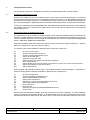
3.1
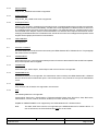
Installing the Software Driver Files
Unzip the file “hss8ntvxyz.zip” to any suitable folder on your local PC Hard Disk Drive (HDD). You must have
administrative privileges on the PC. Run the application “Setup.exe” (Figure 1). All the software driver files will
be extracted to the required locations, i.e. the software driver file will be stored in “WINNT\system32\drivers”,
the control panel applet in “WINNT\system32" and the flash update application in “Program Files\C2I2\HSS8”.
As this is not a Windows Driver Model (WDM) driver, Windows 2000 and XP will report device conflicts between
the software driver and an “Unknown PCI bridge” device. This is due to the NT software driver not supporting
plug and play (PnP).
3.2
Special Instructions for Windows 2000 or XP
The software driver can be installed as a legacy software driver under both Windows 2000 and Windows XP.
However, to obtain optimum performance it is recommended that the "Standard PC" Hard Disk Drive (HAL) be
used. For detailed instruction on how to install the "Standard PC" HAL refer to the Microsoft Knowledge Base
articles : KB237556, KB299340 and KB309283.
During the installation of Windows 2000 or XP, press the F5 key when the text "Setup is inspecting..." appears.
Select the "Standard PC" HAL from the list of options.
To change the HAL after installation of Windows 2000 or XP with an ACPI HAL :
(1)
(2)
(3)
(4)
(5)
(6)
(7)
(8)
(9)
(10)
Go to the Control Panel.
Click the Administrative Tools icon.
Click the Computer Management icon.
Select "Device Manager".
Expand the Computer node.
Select the ACPI item. Right click and select properties.
Click "Update Driver...".
Select "Display a list of known drivers for this device, so that I can choose a specific driver".
Select "All hardware for this device class".
Select "Standard PC".
When installing under Windows 2000 or XP the "Found New Hardware" wizard will appear. To prevent this
wizard at start-up please install the HSS8 NULL software driver ("Hss8null.inf").
(1)
(2)
(3)
(4)
(5)
(6)
(7)
(8)
(9)
(10)
Go to the Control Panel.
Click the Add/Remove Hardware icon.
Select "Add/Troubleshoot a device".
Select "Add a new device".
Select "No, I want to select the hardware from a list".
Select "Multi-channel serial adapters".
Click "Have Disk..."
Click "Browse..."
Select the "Program Files\C2I2\HSS8\hss8null.inf" file.
Click "Finish".
Please note that by default the software driver will not be listed in the Device Manager. To view the adapter,
select View and then “Show hidden devices”. The HSS8 is listed under the “Non-Plug and Play Drivers” node.
Windows will indicate the adapter as an ISA device, this is normal as it is how Windows treats non-PnP drivers.
CCII/HSS8/6-MAN/004
CH8MAN04.WPD
2009-08-31
Issue 1.2
Page 3 of 26
Figure 1 : Installation Wizard
3.3
Uninstalling the Software Driver
In the Start menu, select Control Panel from the Settings menu. Click on “Add/Remove Programs”. Select the
“HSS8 Windows Driver (vX.Y.Z)” from the list and click the Remove button. Answer yes to delete all files from
the HDD.
3.4
Updating the Device Firmware
Always ensure that when a new software driver is installed, the corresponding firmware revision on the device
is identical. There might be incompatibilities between different software driver and firmware versions. The
Engine version reported by the control panel applet must match the firmware version of all devices in the
system.
The flash update application is located in the “Program Files\C2I2\HSS8” folder. Before running the application,
ensure that all channels on the device are closed. The firmware images are located on the supplied CD-ROM
or the C²I² Systems website.
Note :
Do not remove the power from the PC until the flash programming is completed.
The syntax for the application is as follows :
Flashprog.exe # [b s u] filename
#
b
s
u
The channel number residing on the device which will be updated.1
The filename following this flag is a binary image.2
The filename following this flag is a Motorola S-record file.2
No firmware updates will be done, the current firmware image will be stored in filename.
Note :
X.Y.Z is the version of the firmware.
1
Only one channel per device must be specified.
2
Whenever the firmware is updated, the current firmware will be stored in the file "ccbackup.bin". Rename
this file before using the application again.
Example :
flashprog 1 s ccHss8EmbVxyz.hex
Will update the firmware of the first device with the S-record file ccHss8EmbVvxyz.hex. Using channel
number 13 will update the firmware on the second device.
CCII/HSS8/6-MAN/004
CH8MAN04.WPD
2009-08-31
Issue 1.2
Page 4 of 26
3.5
Using the Event Viewer
The Windows administrative tool, “Event Viewer” can be used to inspect the event logs. The HSS8 Windows
NT 4 Software Driver logs certain information and fatal errors to the event log. Refer to the event log when an
operation does not function as expected.
(1)
(2)
(3)
CCII/HSS8/6-MAN/004
CH8MAN04.WPD
Go to the Control Panel.
Click the Administrative Tools icon.
Click the Event Viewer icon.
2009-08-31
Issue 1.2
Page 5 of 26
4.
Application Program Interface (API)
The HSS8 Windows NT Software Driver complies to most of the Windows 32 API for serial devices, i.e.
channels can be opened and used in the Windows HyperTerminal application. Refer to the Platform SDK in
[2.1.4] for the communications resource documentation. The serial function prototypes can be found in the SDK
file “winbase.h”.
The device channels are named HSS8_1 to HSS8_12. HSS8_1 to HSS8_8 are the SCC channels, HSS8_9
to HSS8_12 are the SMC channels.
4.1
Windows SDK Serial Functions
This paragraph lists the serial functions supported by the HSS8 Windows NT 4 Software Driver :
C
C
C
C
C
C
C
C
C
C
C
C
C
C
C
C
C
C
C
C
C
C
4.2
BuildCommDCB
BuildCommDCBAndTimeouts
ClearCommError
CommConfigDialog
GetCommConfig
GetCommMask
GetCommProperties
GetCommState
GetCommTimeouts
GetDefaultCommConfig
PurgeComm
SetCommConfig
SetCommMask
SetCommState
SetCommTimeouts
SetDefaultCommConfig
SetupComm
WaitCommEvent
CreateFile
ReadFile
WriteFile
CloseHandle
Windows SDK Serial Structures
This paragraph lists the serial structures supported by the HSS8 Windows NT 4 Software Driver :
C
C
C
C
C
4.3
COMMCONFIG
COMMPROP
COMMTIMEOUTS
COMSTAT
DCB
Function Limitations
Not all settings are supported for each serial function. This paragraph will mention all the exceptions.
4.3.1
ClearCommError
Only CE_FRAME and CE_RXPARITY are supported.
4.3.2
GetCommMask
Only the EV_RXCHAR event mask is supported.
CCII/HSS8/6-MAN/004
CH8MAN04.WPD
2009-08-31
Issue 1.2
Page 6 of 26
4.3.3
SetCommMask
Only the EV_RXCHAR event mask is supported.
4.3.4
WaitCommEvent
Only the EV_RX_CHAR event mask is supported.
4.3.5
Overlapped Writes
When a port is opened in overlapped (non-blocking) mode, overlapped writes might not behave as expected.
An overlapped read will return immediately, and the event will be signalled once data has been received. For
an overlapped write the function will not return immediately. The HSS8 Windows NT 4 Software Driver has to
send the data to the adapter, where it will be transmitted. This transfer does require a finite amount of time.
Changing the HSS8 Windows NT 4 Software Driver architecture to match the overlapped read operation would
degrade its throughput performance on transmission.
4.3.6
FlushFileBuffers
Not supported.
4.4
Structure Limitations
Not all the fields of the serial structures are used by the HSS8 Windows NT 4 Software Driver. This paragraph
will mention all the exceptions.
4.4.1
COMMCONFIG
dwProviderSubType : none of the types makes provision for a device that is both RS-232 and RS-422 capable.
No provider-specific data is supplied.
4.4.2
COMMPROP
dwProvSubType, dwProvSpec1, dwProvSpec2 and wcProvChar are not supported.
4.4.3
COMMTIMEOUTS
ReadIntervalTimeout is not supported. The write timeout value is used by the HSS8 Windows NT 4 Software
Driver to flush its internal transmitter queue. The internal queue is only used when one byte is transmitted at
a time.
4.4.4
COMSTAT
Only cbInQue and cbOutQue are supported in this structure.
4.4.5
DCB
The following fields are not supported :
fOutxDsrFlow, fDtrControl , fDsrSensitivity, fTXContinueOnXoff, fOutX, fInX, fErrorChar, fNull, fRtsControl,
fAbortOnError, XonLim, XoffLim, XonChar, XoffChar, ErrorChar, EofChar, EvtChar.
StopBits of ONE5STOPBITS is not supported by the HSS8 Windows NT 4 Software Driver.
Note :
CCII/HSS8/6-MAN/004
CH8MAN04.WPD
The XON, XOFF flow control is not supported by the HSS8 Windows NT 4 Software Driver. To
use no flowcontrol, the fOutxCtsFlow field must be set to FALSE.
2009-08-31
Issue 1.2
Page 7 of 26
5.
HSS8 Windows NT 4 Software Driver Protocol Settings
The HSS8 has eight serial communications controllers (SCCs) [Channels 1-8] that support UART and
HDLC/SDLC protocols, and four serial management controllers (SMCs) [Channels 9-12] that support only
asynchronous UART.
The control panel applet allows the user to set all the protocol-specific options available on the
HSS8 communication controller chip (the MPC8260 PowerQUICC II™). For available options for each of the
fields, see [2.1.1].
This section details the information used by each protocol and explains the use and limitations of every
member.
5.1
Protocol Selection
Each Channel must be configured to use a protocol.
Protocol :
UART
HDLC
BISYNC
SMC_UART
The protocol settings for the device can be set through a control panel applet. Access the applet by clicking on
the Start menu and selecting the Control Panel from the Settings option. Click on the icon shown in Figure 2.
Figure 2 : Applet Icon
5.2
Using the Control Panel to Change Channel Settings
The control panel applet selection boxes list available options for the specific protocols. Options that are not
available for the selected protocol are grayed out. All the options (including the options in the Advanced
dialogue) must be entered to create a valid protocol setting. Always click the Apply button before closing any
of the dialogue windows. The settings are applied to the HSS8 Channel when it is reopened.
When “Lock Settings” is checked, all requests via the Win32 API will be ignored. Any change in baud rate or
parity will then not be updated, the HSS8 Windows NT 4 Software Driver will keep the setting as specified in
the control panel. When the settings are not locked, the baud rate, etc. may be updated via the Win32 API
functions.
When using the HDLC or BISYNC protocols, it is recommended to use the “Lock Settings” option.
The settings are stored in the Windows registry, under the keys :
“HKEY_LOCAL_MACHINE\SYSTEM\CurrentControlSet\Services\HSS8\DeviceX\PortX”
CCII/HSS8/6-MAN/004
CH8MAN04.WPD
2009-08-31
Issue 1.2
Page 8 of 26
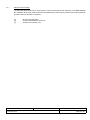
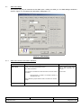
5.3
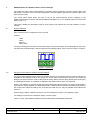
Using the Control Panel to Obtain the Current Version Information
Clicking on the Information icon near the bottom of the dialogue screen will display the HSS8 Windows NT 4
Software Driver information dialogue shown in Figure 3.
The Driver version is referring to the HSS8 Windows NT 4 Software Driver itself. It has the format X.Y.Z. A
change in X would indicate that the HSS8 Windows NT 4 Software Driver has an added feature. Y would mean
that a new software driver engine is used in the software driver. Z indicates any corrections to problems in the
HSS8 Windows NT 4 Software Driver.
The Engine version must be identical to the firmware version for all cards in the PC. Normally this would only
be different when the software driver version is checked after a firmware update and the software driver itself
has not been updated.
Figure 3 : Driver Information Dialogue
CCII/HSS8/6-MAN/004
CH8MAN04.WPD
2009-08-31
Issue 1.2
Page 9 of 26
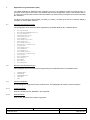
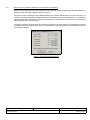
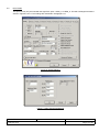
5.4
UART Mode
This protocol may only be used with the eight SCC Channels : HSS8_1 to HSS8_8. See Paragraph 5.7.1 for
the settings for the SMC Channels. The UART dialogue window is shown in Figures 4 and 5. The settings are
described in Paragraph 5.4.1.
Figure 4 : UART Dialogue
Figure 5 : UART Advanced Dialogue
CCII/HSS8/6-MAN/004
CH8MAN04.WPD
2009-08-31
Issue 1.2
Page 10 of 26
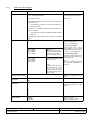
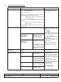
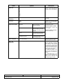
5.4.1
UART Protocol Information
Name
Baud Rate
Options
Description
1 200 - 1 Mbit/s (RS-232)
1 200 - 16 Mbit/s (RS-422/485)
Used to specify a single baud rate
for both transmitter and receiver.
Any values permissible.
Units in bit/s.
The equation to calculate the actual baud rate for asynchronous
UART is as follows :
Actual baud rate = 100 MHz / 16 / ROUND (100 MHz / 16 /
Desired baud rate)
The equation to calculate the actual baud rate for synchronous
UART is as follows :
Actual baud rate = 100 MHz / ROUND (100 MHz / Desired
baud rate)
Where ROUND () implies that the result is rounded to the nearest
integer.
Clock Source
CLOCK_DEFAULT
CLOCK_DEFAULT connects Baud
Rate Generators (BRGs) [1 - 4] to
Ports [1 - 4] and Ports [5 - 8].
CLOCK_BRG1
CLOCK_BRG2
CLOCK_BRG3
CLOCK_BRG4
BRGs [1 - 4]
BRG1 for Ports [1 and 5].
BRG2 for Ports [2 and 6].
BRG3 for Ports [3 and 7].
BRG4 for Ports [4 and 8].
CLOCK_EXT1
CLOCK_EXT2
CLOCK_EXT3
CLOCK_EXT4
External Clocks connected
on CLK_IN pins.
Note :
CLOCK_EXT[1-2] can only
be used for Ports [1 and 2]
and [5 and 6], while
CLOCK_EXT[3-4] can only
be used for Ports [3 and 4]
and [7 and 8].
For synchronous UART :
When transmit clock is set to
CLOCK_BRG[1-4], then receive
clock is still set to CLOCK_EXT[1-4]
for Ports [1 - 4] and Ports [5 - 8].
For asynchronous UART :
Transmit and receive clocks can be
set to one of CLOCK_BRG[1-4] or
CLOCK_EXT[1-4].
Note :
There are four BRGs and four clock
input pins per PowerQUICC II
processor.
Normal
control.
Async. Flow Control
or
asynchronous
flow
Stop bits
ONE
TWO
Number of full stop bits.
Data Bits
5
6
7
8
9
10
11
12
13
14
Number of data bits. Note only
Ports [9-12] support nine or more
data bits.
UART Mode
NORMAL
MAN MM
AUTO MM
Select UART mode :
Normal, manual multidrop
automatic multidrop mode.
CCII/HSS8/6-MAN/004
CH8MAN04.WPD
2009-08-31
or
Issue 1.2
Page 11 of 26
Name
Options
Description
Freeze Transmit
Pause (freeze) transmission.
Transmission continues when set
back to normal.
RX with no stopbit
If set, the receiver receives data
without stop bits.
Sync. Mode
Select asynchronous (normal) or
synchronous mode.
Disable RX while TX
Enable (normal) or disable receiver
while transmitting. Used in
multidrop mode to prevent
reception of own messages.
Disable
Checking
Enable or disable parity checking.
Parity
TX parity, RX parity
ODD
LOW
EVEN
HIGH
Diagnostics Mode
NORMAL
LOOPBACK
Receive and transmit parity. Parity
will only be checked if parity is
enabled.
Normal operation. Use this
for external loopback.
Internal loopback :
TxD and RxD are
connected internally. The
value on RxD, CTS and CD
is ignored. The transmitter
and receiver share the
same clock source.
ECHO
The
transmitter
automatically resends
received data bit-by-bit.
LOOPBACK_ECHO
Loop b a c k and echo
operation
occur
simultaneously.
Set diagnostic mode.
External loopback - RS-422/485 :
Connect TxD+ to RxD+, TxD- to
RxD-, (CLK_OUT+ to CLKIN+ and
CLKOUT- to CLK_IN- for
synchronous mode).
External loopback - RS-232 :
Connect TxD to RxD, (CLK_OUT to
CLK_IN for synchronous mode) and
RTS to CTS and CD.
Max. RX Bytes
1 to 16 384 (default)
Maximum number of bytes that may
be copied into a buffer.
Max. Idle Characters
0 to 16 384 (default)
Maximum idle characters. When a
character is received, the receiver
begins counting idle characters. If
max_idl idle characters are
received before the next data
character, an idle timeout occurs
and the buffer is closed. Thus,
max_idl offers a way to demarcate
frames.
To disable the feature, clear
max_idl. The bit length of an idle
character is calculated as follows:
1 + data length (5-9) + 1 (if parity is
used) + number of stop bits (1-2).
For 8 data bits, no parity, and 1 stop
bit, the character length is 10 bits.
Break Characters
0 - 2 048
Number of break characters sent by
transmitter. For 8 data bits, no
parity, 1 stop bit, and 1 start bit,
each break character consists of 10
zero bits.
Address1, Address2
0x0000 - 0x00FF
Address in multidrop mode. Only
the lower 8 bits are used so the
upper 8 bits should be cleared.
CCII/HSS8/6-MAN/004
CH8MAN04.WPD
2009-08-31
Issue 1.2
Page 12 of 26
Name
Control Characters[8]
Options
0b00------cccccccc 0b10------cccccccc -
Valid entry.
Entry not valid and is not used.
Description
Control character 1 to 8. These
characters can be used to delimit
received messages.
------ (6 bits) Reserved. Initialise to zero.
cccccccc (8 bits) Defines control characters to be
compared to the incoming
character.
RX Control Character
Mask
CCII/HSS8/6-MAN/004
CH8MAN04.WPD
0b11------00000000 0b11------11111111 -
Ignore these bits when comparing
incoming character.
Enable comparing the incoming
character to cc[n].
2009-08-31
Receive control character mask. A
one enables comparison and a zero
masks it.
Issue 1.2
Page 13 of 26
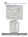
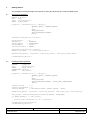
5.5
HDLC Mode
This protocol may only be used with the eight SCC ports : HSS8_1 to HSS8_8. The HDLC dialogue windows is
shown in Figures 6 and 7. The settings are described in Paragraph 5.5.1.
Figure 6 : HDLC Dialogue
Figure 7 : HDLC Advanced Dialogue
CCII/HSS8/6-MAN/004
CH8MAN04.WPD
2009-08-31
Issue 1.2
Page 14 of 26
5.5.1
HDLC Protocol Information Members
Name
Baud Rate
Options
Description
1 200 - 1 Mbit/s (RS-232)
1 200 - 16 Mbit/s (RS-422/485)
Used to specify a single baud rate for
both transmitter and receiver.
Any values permissible.
Units in bit/s.
The equation to calculate the actual baud rate for FM0/1,
Manchester and Diff. Manchester is as follows :
Actual baud rate = 100 MHz / 16 / ROUND (100 MHz
/ 16 / Desired baud rate)
The equation to calculate the actual baud rate for NRZ/NRZI is
as follows :
Actual baud rate = 100 MHz / ROUND (100 MHz /
Desired baud rate)
Where ROUND () implies that the result is rounded to the
nearest integer.
Clock Source
CLOCK_DEFAULT
CLOCK_BRG1
CLOCK_BRG2
CLOCK_BRG3
CLOCK_BRG4
BRG [1 - 4]
BRG1 for Ports [1 and 5]
BRG2 for Ports [2 and 6]
BRG3 for Ports [3 and 7]
BRG4 for Ports [4 and 8]
CLOCK_EXT1
CLOCK_EXT2
CLOCK_EXT3
CLOCK_EXT4
External Clocks connected on
CLK_IN Pins.
CRC Mode
16-bit
32-bit
Diagnostics Mode
NORMAL
LOOPBACK
CCII/HSS8/6-MAN/004
CH8MAN04.WPD
CLOCK_DEFAULT connects
BRGs [1 - 4] to Ports [1 - 4] and
Ports [5 - 8].
Note :
CLOCK_EXT[1-2] can only be
used for Ports [1 and 2] and
[5
and
6],
while
CLOCK_EXT[3-4] can only be
used for Ports [3 and 4] and
[7 and 8].
For NRZ/NRZI :
When transmit clock is set to
CLOCK_BRG [1-4], then receive
clock is still set to CLOCK_EXT[1-4]
for Ports [1 - 4] and [5 - 8].
For FM0/1, Manchester and Diff.
Manchester :
Transmit and receive clocks can be
set to one of CLOCK_BRG [1 - 4] or
CLOCK_EXT[1-4].
Note :
There are four BRGs and four clock
input pins per PowerQUICC II
processor.
HDLC CRC mode.
Normal operation. Use this for
external loopback.
Internal loopback :
TxD and RxD are connected
internally. The value on RxD,
CTS and CD is ignored. The
transmitter and receiver share
the same clock source.
ECHO
The transmitter automatically
resends received data bit-bybit.
LOOPBACK_ECHO
Loopback and echo operation
occur simultaneously.
2009-08-31
Set diagnostic mode.
External loopback - RS-422/485 :
Connect TxD+ to RxD+, TxD- to
RxD-, (CLK_OUT+ to CLK_IN+ and
CLK_OUT- to CLK_IN- for
synchronous mode).
External loopback - RS-232 :
Connect TxD to RxD, (CLK_OUT to
CLK_IN for synchronous mode) and
RTS to CTS and CD.
Set diagnostic mode.
For synchronous mode :
see encoding_method.
Issue 1.2
Page 15 of 26
Name
Options
Description
Max. RX Bytes
1 to (16 384 - CRC bytes (two or four)) (default)
Maximum number of bytes to receive
before closing buffer.
Set equal to max_frame_bytes.
Max. Frame Bytes
1 to 16 384 (default)
Maximum number of bytes per
frame. Set equal to the number of
data bytes plus the number of CRC
bytes (either two or four) per frame.
Address Mask
0x0000 - 0xFFFF
HDLC address mask. A one enables
comparison and a zero masks it.
Address[4]
0x0000 - 0xFFFF
Four address registers for address
recognition. The SCC reads the
frame address from the HDLC
receiver, compares it with the
address registers, and masks the
result with address_mask.
For example, to recognize a frame
that begins 0x7E (flag), 0x68, 0xAA,
using 16-bit address recognition, the
address registers should contain
0xAA68 and address_mask should
contain 0xFFFF. For 8-bit addresses,
clear the eight high-order address
bits.
Flags between Frames
0 - 15
Minimum number of flags between or
before frames.
Enable Retransmit
Enable re-transmit.
Enable Flag Sharing
Enable flag sharing.
Disable RX while TX
Disable receive during transmit.
Enable Bus Mode
Enable bus mode.
Enable RTS Mode
Enable special RTS operation in
HDLC bus mode.
Enable Multiple Frames
Enable multiple frames in transmit
FIFO.
Encoding Method
NRZ
NRZI_MARK
NRZI_SPACE
FM0
FM1
MANCHESTER
DIFF_MANCHESTER
RX / TX encoding method. NRZ and
NRZI use no DPLL. FM0/1,
Manchester and Diff_Manchester
use the DPLL for clock recovery.The
clock rate is 16x when the DPLL is
used.
Preamble Length
0
8
16
32
48
64
128
Determines the length
preamble pattern.
of
Pattern
00
10
01
11
Determines what bit
precedes each TX frame.
pattern
Send either idles or flags/syncs
between frames as defined by the
protocol. For HDLC the flag is
defined as 0x7E. NRZI encoding
methods may only be used with
flags/syncs.
Send flags/sync
CCII/HSS8/6-MAN/004
CH8MAN04.WPD
the
2009-08-31
Issue 1.2
Page 16 of 26
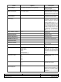
5.5.2
Preamble Requirements
Preamble Pattern
Minimum Preamble Length
Required
NRZI Mark
All zeros
8-bit
NRZI Space
All ones
8-bit
FM0
All ones
8-bit
FM1
All zeros
8-bit
101010...10
8-bit
All ones
8-bit
Decoding Method
Manchester
Differential Manchester
CCII/HSS8/6-MAN/004
CH8MAN04.WPD
2009-08-31
Issue 1.2
Page 17 of 26
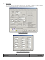
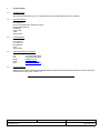
5.6
BISYNC Mode
This protocol may only be used with the eight SCC ports : Ports HSS8_1 to HSS8_8. The BISYNC dialogue
windows is shown in Figures 8 and 9. The settings are described in Paragraph 5.6.1.
Figure 8 : BISYNC Dialogue
Figure 9 : BISYNC Advanced Dialogue
CCII/HSS8/6-MAN/004
CH8MAN04.WPD
2009-08-31
Issue 1.2
Page 18 of 26
5.6.1
BISYNC Protocol Information Members
Name
Baud Rate
Options
Description
1 200 - 1 Mbit/s (RS-232)
1 200 - 16 Mbit/s (RS-422/485)
Used to specify a single baud rate for
both transmitter and receiver.
Any values permissible.
Units in bit/s.
The equation to calculate the actual baud rate for BISYNC is as
follows :
Actual baud rate = 100 MHz / ROUND (100 MHz / Desired
baud rate)
Where ROUND () implies that the result is rounded to the nearest
integer.
Clock Source
CLOCK_DEFAULT
CLOCK_DEFAULT connects
BRGs [1 - 4] to Ports [1 - 4] and [5 - 8].
CLOCK_BRG1
CLOCK_BRG2
CLOCK_BRG3
CLOCK_BRG4
BRGs [1 - 4]
BRG1 for Ports [1 and 5]
BRG2 for Ports [2 and 6]
BRG3 for Ports [3 and 7]
BRG4 for Ports [4 and 8]
CLOCK_EXT1
CLOCK_EXT2
CLOCK_EXT3
CLOCK_EXT4
External Clocks connected
on CLK_IN Pins.
When transmit clock is set to
CLOCK_BRG [1-4], then receive clock
is still set to CLOCK_EXT[1-4] for
Ports [1 - 4] and [5 - 8].
Note :
There are four BRGs and four clock
input pins per PowerQUICC II
processor.
Note :
CLOCK_EXT[1-2] can only
be used for Ports [1 and 2]
and [5 and 6], while
CLOCK_EXT[3-4] can only
be used for Ports [3 and 4]
and [7 and 8].
Max. RX Bytes
1 to (16 384 - 2 CRC bytes) (default)
Maximum number of bytes to receive
before closing buffer.
Min. Sync Pairs
0b0000 (0 pairs) - 0b1111 (16 pairs)
Minimum number of SYN1-SYN2 pairs
sent between or before messages. The
entire pair is always sent, regardless of
the syn_length variable.
CRC Select
16
LRC
CRC selection.
1. CRC16 (X16 + X15 + X2 + 1) :
Initialise prcrc and ptcrc to all zeros
or all ones.
2. LRC (sum check) :
For even LRC, initialise prcrc and
ptcrc to zeros, for odd LRC initialise to
ones.
Enable Receive
Sequence (BCS).
Enable RX BCS
CCII/HSS8/6-MAN/004
CH8MAN04.WPD
2009-08-31
Block
Check
Issue 1.2
Page 19 of 26
Name
Enable
Mode
RX
Options
Description
Enable Receiver transparent mode.
Transparent
FALSE :
Normal receiver mode with SYNC
stripping and control character
recognition.
TRUE :
Transparent receiver mode. SYNC’s,
DLE’s and control characters are
recognised only after the leading DLE
character. The receiver calculates the
CRC16 sequence even if it is
programmed to LRC while in
transparent mode. Initialize prcrc to
the CRC16 preset value before setting
rx_transparant_mode.
Enable Reverse Data
Enable Reverse data.
Disable RX while TX
Disable receiver while sending.
RX Parity,
TX Parity
ODD
LOW
EVEN
HIGH
Diagnostics Mode
NORMAL
LOOPBACK
Receive and transmit parity. Parity is
ignored unless crc_select = LRC.
Normal operation. Use this
for external loopback.
Internal loopback :
TxD and RxD are connected
internally. The value on RxD,
CTS and CD is ignored. The
transmitter and receiver
share the same clock
source.
ECHO
The transmitter automatically
resends received data bitby-bit.
LOOPBACK_ECHO
Loopback and echo
operation
occur
simultaneously.
Set diagnostic mode.
External loopback - RS-422/485 :
Connect TxD+ to RxD+, TxD- to RxD-,
CLK_OUT+ to CLK_IN+ and
CLK_OUT- to CLK_IN-.
External loopback - RS-232 :
Connect TxD to RxD, CLK_OUT to
CLK_IN and RTS to CTS and CD.
CRC Constant
0
CRC constant value.
CRC Preset RX
CRC Preset TX
0x0000 or
0xFFFF
Preset receiver / transmitter
CRC16/LRC. These values should be
preset to all ones or zeros, depending
on the BCS used.
CCII/HSS8/6-MAN/004
CH8MAN04.WPD
2009-08-31
Issue 1.2
Page 20 of 26
Name
SYNC register
Options
0bv0000000ssssssss
Description
BISYNC SYNC register. Contains the
value of the SYNC character stripped
from incoming
data on receive once the receiver
synchronizes to the data using the
SYN1- SYN2 pair.
vIf v = 1 and the receiver is not in hunt
mode when a SYNC character is
received, this character is discarded.
ssssssss (8 bits) SYNC character. When using 7-bit
characters with parity, the parity bit
should be included in the SYNC
register value.
DLE register
0bv0000000dddddddd
BISYNC DLE register. In transparent
mode, the receiver discards any DLE
character received.
vIf v = 1 and the receiver is not in hunt
mode when a DLE character is
received, this character is discarded.
dddddddd (8 bits) DLE character. This character tells the
receiver that the next character is text.
Control Characters[8]
0b0bh-----cccccccc 0b1bh-----cccccccc -
Valid entry.
Entry not valid and is not used.
Control character 1 to 8.
----- (5 bits) Reserved. Initialise to zero.
bBlock check sequence expected. A
maskable interrupt is generated after
the buffer is closed.
b=0
The character is written into the
receive buffer and the buffer is closed.
b=1
The character is written into the
receive buffer. The receiver waits for 1
LRC or 2 CRC bytes and then closes
the buffer.
hEnables hunt mode when the current
buffer is closed.
h=0
The BISYNC controller maintains
character synchronisation after closing
the buffer.
h=1
The BISYNC controller enters hunt
mode after closing the buffer. When
b = 1, the controller enters hunt mode
after receiving LRC or CRC.
cccccccc (8 bits) Defines control characters to be
compared to the incoming character.
When using 7-bit characters with
parity, include the parity bit in the
character value.
CCII/HSS8/6-MAN/004
CH8MAN04.WPD
2009-08-31
Issue 1.2
Page 21 of 26
Name
RX Control Character Mask
Options
0b11------00000000 0b11------11111111 -
Ignore these bits when comparing
incoming character.
Enable comparing the incoming
character to cc[n].
Description
Receive control character mask. A one
enables comparison and a zero masks
it.
Sync. Character
0xssss (2 bytes)
SYNC character :
Should be programmed with the sync
pattern.
Syn Length
8
16
SYNL_8
Should be chosen to implement
mono-sync protocol. The
receiver synchronizes on an 8-bit sync
pattern in sync.
SYNL_16
The receiver synchronizes on a 16-bit
sync pattern stored in sync.
Send either idles or flags/syncs
between frames as defined by the
protocol. The flag character is equal to
sync.
Enable flags/syncs
CCII/HSS8/6-MAN/004
CH8MAN04.WPD
2009-08-31
Issue 1.2
Page 22 of 26
5.7
SMC UART Mode
This protocol may only be used with the four SMC ports : HSS8_9 to HSS8_12. The SMC dialogue window is
shown in Figure 10. The settings are described in Paragraph 5.7.1.
Figure 10 : SMC Dialogue
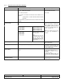
5.7.1
SMC UART Protocol Information Members
Name
Baud Rate
Options
1 200 - 115.2 kbit/s (RS-232/RS-422/485)
Any values permissible.
The equation to calculate the actual baud rate for the SMC UART is
as follows :
Description
Used to specify a single baud
rate for both transmitter and
receiver.
Units in bit/s.
Actual baud rate = 100 MHz / 16 / ROUND (100 MHz / 16
/ Desired baud rate)
Where ROUND () implies that the result is rounded to the nearest
integer.
Stop bits
CCII/HSS8/6-MAN/004
CH8MAN04.WPD
One
Two
Number of full stop bits.
2009-08-31
Issue 1.2
Page 23 of 26
Name
Data Bits
Options
5
6
7
8
9
10
11
12
13
14
Description
Number of data bits. Note only
ports 9 - 12 (i.e. the SMC ports)
support nine or more data bits.
Enable or
checking.
Disable Parity
Checking
TX Parity
ODD
EVEN
Diagnostics Mode
NORMAL
LOOPBACK
disable
parity
Receive and transmit parity.
Parity will only be checked if
parity is enabled.
Normal operation. Use this for
external loopback.
Internal loopback :
TxD and RxD are connected
internally. The value on RxD is
ignored.
ECHO
The transmitter automatically
resends received data bit-bybit.
LOOPBACK_ECHO
Loopback and echo operation
occur simultaneously.
Set diagnostic mode.
External loopback - RS485 :
Connect TxD+ to RxD+ and
TxD- to RxD-.
External loopback - RS-232 :
Connect TxD to RxD.
Max. RX Bytes
1 to 16 384 (default)
Maximum number of bytes that
may be copied into a buffer.
Max. Idle
Characters
0 to 16 384 (default)
Maxi mum i d l e c h a r ac ters .
When a character is received,
the receiver begins counting
idle characters. If max_idl idle
characters are received before
the next data character, an idle
timeout occurs and the buffer is
closed. Thus, max_idl offers a
way to demarcate frames.
To disable the feature, clear
max_idl. The bit length of an
idle character is calculated as
follows :
1 + data length (5-14) + 1 (if
parity is used) + number of stop
bits (1-2). For 8 data bits, no
parity, and 1 stop bit, the
character length is 10 bits.
CCII/HSS8/6-MAN/004
CH8MAN04.WPD
2009-08-31
Issue 1.2
Page 24 of 26
6.
Getting Started
This paragraph contains example code extracts for using the Win32 API to access the HSS8 device.
6.1
Normal Write Operation
HANDLE
DCB
char
DWORD
h_device;
dcb;
tx_buffer[100];
bytes_send;
h_device = CreateFile("\\\\.\\HSS8_1",
GENERIC_READ | GENERIC_WRITE,
0,
NULL,
OPEN_EXISTING,
FILE_ATTRIBUTE_NORMAL,
NULL);
GetCommState(h_device, and dcb);
dcb.ByteSize
dcb.Parity
dcb.StopBits
dcb.BaudRate
dcb.fOutxCtsFlow
=
=
=
=
=
8;
NOPARITY;
ONESTOPBIT;
115200;
FALSE;
SetCommState(h_device, and dcb);
memset(tx_buffer, ‘*’, sizeof(tx_buffer));
WriteFile(h_device, tx_buffer, sizeof(tx_buffer), and bytes_send, NULL);
CloseHandle(h_device);
6.2
Overlapped Read Operation
HANDLE
char
DWORD
OVERLAPPED
DWORD
h_device;
rx_buffer[100];
bytes_read;
overlap;
wait_event;
h_device = CreateFile("\\\\.\\HSS8_1",
GENERIC_READ | GENERIC_WRITE,
0,
NULL,
OPEN_EXISTING,
FILE_ATTRIBUTE_NORMAL | FILE_FLAG_OVERLAPPED,
NULL);
overlap.Offset
= 0;
overlap.OffsetHigh = 0;
overlap.hEvent
= CreateEvent(NULL, FALSE, FALSE,
NULL);
ReadFile(h_device, rx_buffer, sizeof(rx_buffer), and bytes_read, and overlap);
wait_event = WaitForSingleObject(overlap.hEvent, INFINITE);
if (WAIT_OBJECT_0 == wait_event)
{
printf(“Data received= %s.\n”, rx_buffer);
}
CloseHandle(overlap.hEvent);
CloseHandle(h_device);
CCII/HSS8/6-MAN/004
CH8MAN04.WPD
2009-08-31
Issue 1.2
Page 25 of 26
7.
Contact Details
7.1
Contact Person
Direct all correspondence and / or support queries to the Project Manager at C²I² Systems.
7.2
Physical Address
C²I² Systems
Unit 3, Rosmead Place, Rosmead Centre
67 Rosmead Avenue
Kenilworth
Cape Town
7708
South Africa
7.3
Postal Address
C²I² Systems
P.O. Box 171
Rondebosch
7701
South Africa
7.4
Voice and Electronic Contacts
Tel
Fax
Email
Email
URL
7.5
:
:
:
:
:
(+27) (0)21 683 5490
(+27) (0)21 683 5435
[email protected]
[email protected]
http://www.ccii.co.za/
Product Support
Support on C²I² Systems products is available telephonically between Monday and Friday from 09:00 to 17:00 CAT.
Central African Time (CAT = GMT + 2).
CCII/HSS8/6-MAN/004
CH8MAN04.WPD
2009-08-31
Issue 1.2
Page 26 of 26