1
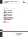
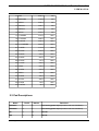
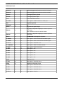
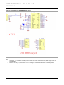
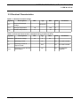
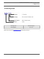
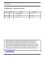
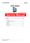
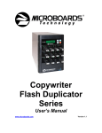
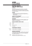
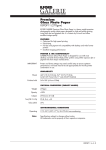
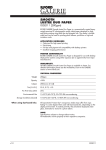
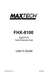
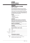
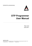
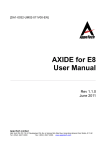
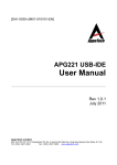
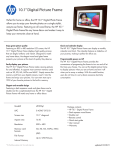
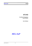
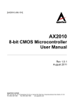
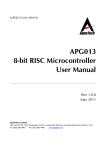
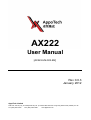
AX222
User Manual
[AX222-UM-003-EN]
Rev 0.0.3
January 2012
AppoTech Limited
Add: Unit 705-707, 7/F, IC Development Ctr, No. 6, Science Park West Ave. Hong Kong Science Park, Shatin, N.T. HK
Tel: (852) 2607 4090
Fax: (852) 2607 4096
www.appotech.com
AX222 SD/MMC/MS Card Reader
Controller
High performance SOC
USB Features
• Support USB specification v2.0
• Support USB Storage Class specification v1.0
SD Card Features
• Support SD specification v2.0
• Support SDHC card up to 32GB
• Support write protection
• Support hot plug and removal
MMC Card Features
• Support MMC specification v4.2
• Support MMC card up to 32GB
• Support hot plug and removal
MS/MSPRO Features
• Support MS specification v1.43
• Support MSPRO specification v1.03
• Support MS PRO-HG Duo specification v1.01
• Support 1/4/8 bit bus mode
• Support card up to 32GB
LED Driver IO
Dual voltage regulator
AppoTech Limited
Address
:Unit 705-707, 7/F, IC Development Centre,
No.6, Science Park West Ave.,
Hong Kong Science Park,
Shatin, N.T., Hong Kong
Telephone
:(852) 2607 4090
Fax
:(852) 2607 4096
www.appotech.com
AX222 SD/MMC/MS Card Reader Controller
Preliminary Rev 0.0.3
USER MANUAL
1 Architecture Overview
1.1 System architecture
Figure 1-1: AX222 hardware architecture
SD / MMC
Controller
DMA
Controller
SOC
MS / MSPRO
Controller
SRAM
MS /
MSPRO
Stick
Mask ROM
USB
Controller
© 2010 AppoTech Ltd
SD / MMC
Card
USB
PHY
3
AX222 SD/MMC/MS Card Reader/Controller as
Preliminary Rev 0.0.3
USER MANUAL
2 PIN DEFINITIONS
Test
D0
D1
D2
VDDIO
D3
VSSIO
NC
NC
NC
NC
NC
WP
CMD/BS
CLK
SDIN
MSIN
2.1 Pin Assignment
VSS
NC
VDD50
VREG33
VREG18
SDV33
LED
TCLK
UVDD33T
UVDD33P
DP
DM
UVSS33T
UVSS33P
UVSS18
UVDD18
1002.15um
1595.34um
Die Size: 1595.34um (Width) x 1002.15um (Height)
Table 2-1: Pad Coordinates
Pin No.
Name
Y-axis(um)
1 UVDD33T
39.8
38.7
2 UVDD33P
123.8
38.7
3 DP
208.4
38.7
4 DM
292.9
38.7
5 UVSS33T
376.2
38.7
6 UVSS33P
460.5
38.7
7 UVSS18
559.9
38.7
8 UVDD18
645.7
38.7
9 TCLK
824.9
38.7
973.2
38.7
10 P1.2/LED
4
X-axis (um)
© 2010 AppoTech Ltd
AX222 SD/MMC/MS Card Reader Controller
Preliminary Rev 0.0.3
USER MANUAL
11 VSS
1093.1
38.7
12 VDD50/NC
1170.5
38.7
13 VDD50
1238.4
38.7
14 VREG33
1328.1
38.7
15 VREG18
1423.3
38.7
16 SDV33
1529.0
38.7
17 P1.3/MSIN
1474.2
942.7
18 P1.4/SDIN
1385.5
942.7
19 P1.0/CLK
1295.3
942.7
20 P1.1/CMD/BS
1203.0
942.7
21 P1.6/WP
1114.8
942.7
22 P0.7/NC
1034.8
942.7
23 P0.6/NC
949.4
942.7
24 P0.5/NC
863.3
942.7
25 P0.4/NC
777.9
942.7
26 P1.7/NC
693.5
942.7
27 VSSIO
608.0
942.7
28 P0.3/D3
523.2
942.7
29 VDDIO
436.8
942.7
30 P0.2/D2
352.2
942.7
31 P0.1/D1
265.5
942.7
32 P0.0/D0
176.6
942.7
33 P1.5/Test
86.3
942.7
2.2 Pad Descriptions
Name
Pad #
Nature
Functions
UVDD33T
1
P
PHY analog power input (Double-bond with UVDD33P)
UVDD33P
2
P
PHY analog power input (Double-bond with UVDD33T)
DP
3
IO
USB D+
DM
4
IO
USB D-
© 2010 AppoTech Ltd
5
AX222 SD/MMC/MS Card Reader/Controller as
Preliminary Rev 0.0.3
USER MANUAL
UVSS33T
5
P
PHY analog ground (Double-bond with UVSS33P)
UVSS33P
6
P
PHY analog ground (Double-bond with UVSS33T)
UVSS18
7
P
1.8V Digital power ground
UVDD18
8
P
1.8V Digital power input
TCLK
9
I
Test mode external clock
P1.2/LED
10
IO
Port 1 pin 2 – LED0 indication or serial port
VSS
11
P
Regulator ground
VDD50/NC
12
P
NC
VDD50
13
P
Regulator 5V power input
VREG33
14
P
Regulator 3.3V power output (for external capacitor
connection)
Note: VREG33 is short-circuit with VDDIO
VREG18
15
P
Regulator 1.8V power output (for external capacitor
connection)
SDV33
16
P
SD/MMC/MS card output 3.3V power
P1.3/MSIN
17
IO
Port 1 pin 3 – MS card insertion indication signal
P1.4/SDIN
18
IO
Port 1 pin 4 – MDC card insertion indication signal
P1.0/CLK
19
IO
Port 1 pin 0 – MDC/MS clock
P1.1/CMD/BS
20
IO
Port 1 pin 1 – MDC command, MS BS
P1.6/WP
21
IO
Port 1 pin 6 – MDC write protect
P0.7/NC
22
IO
Port 0 pin 7 – NC
P0.6/NC
23
IO
Port 0 pin 6 – NC
P0.5/NC
24
IO
Port 0 pin 5 – NC
P0.4/NC
25
IO
Port 0 pin 4 – NC
P1.7/NC
26
IO
Port 1 pin 7 – NC
VSSIO
27
P
Digital ground
P0.3/D3
28
IO
Port 0 pin 3 – MDC/MS data 3
VDDIO
29
P
Digital I/O 3.3V power input
P0.2/D2
30
IO
Port 0 pin 2 – MDC/MS data 2
P0.1/D1
31
IO
Port 0 pin 1 – MDC/MS data 1
P0.0/D0
32
IO
Port 0 pin 0 – MDC/MS data 0
P1.5/Test
33
IO
Port 1 pin 5 – Test Pin
6
© 2010 AppoTech Ltd
AX222 SD/MMC/MS Card Reader Controller
Preliminary Rev 0.0.3
USER MANUAL
3 DIE SCHEMATICS
3.1 SD/MMC/MS 4-bit Mode
VSS
NC
VDD50
VREG33
VREG18
SDV33
LED
TCLK
UVDD33T
UVDD33P
DP
DM
UVSS33T
UVSS33P
UVSS18
UVDD18
Test
D0
D1
D2
VDDIO
D3
VSSIO
NC
NC
NC
NC
NC
WP
CMD/BS
CLK
SDIN
MSIN
Figure 3-1: Valid pads for SD/MMC/MS 4-bit mode
Note: Only highlighted pads are valid.
Notes :
1.If MS Card is used ,
MSIN must be bonded .
2.If LED is used ,
LED must be bonded .
VSS
NC
VDD50
VREG33
VREG18
SDV33
LED
TCLK
UVDD33T
UVDD33P
DP
DM
UVSS33T
UVSS33P
UVSS18
UVDD18
Test
D0
D1
D2
VDDIO
D3
VSSIO
NC
NC
NC
NC
NC
WP
CMD/BS
CLK
SDIN
MSIN
Figure 3-2: Bonding Diagram for 4-bit Mode (SD/MMC/MS Card)
4 bit mode
© 2010 AppoTech Ltd
7
AX222 SD/MMC/MS Card Reader/Controller as
Preliminary Rev 0.0.3
USER MANUAL
Figure 3-3: Schematic for SD/MMC/MS 4-bit mode
Note:
1.
2.
3.
8
Choose R1, C1, C3 and C4 according to your needs. Lower value can minimize cost, while a higher value can
provide stability.
Place C3 close to pin 2, and C4 close to pin 11. Routing for 3.3V and 1.8V should be as short as possible.
NC = Not Connected.
© 2010 AppoTech Ltd
AX222 SD/MMC/MS Card Reader Controller
Preliminary Rev 0.0.3
USER MANUAL
3.2 Electrical Characteristics
Table 3-1: Absolute maximum ratings
Symbol
Descriptions
Min
Typ
Max
Units
VESD
Electrical Discharge
Voltage
-
Passed 8k
-
V
TSTOR
Storage Temperature
-40
-
125
o
C
TAMB
Ambient Temperature
0
-
70
o
C
Conditions
Table 3-2: Electrical Characteristics (Standard testing condition at 25 oC)
Symbol
Descriptions
Min
Typ
Max
USBVDD
USB supply voltage
4.5
5
5.5
IDD
Operating current
-
56
-
mA
No cards inserted
ISUP
Operating current at
suspend mode
-
0.37
-
mA
No cards inserted
ISDIDLE
Operating current with SD
card inserted
-
62
-
mA
No read/write
operation
© 2010 AppoTech Ltd
Units
Conditions
V
9
AX222 SD/MMC/MS Card Reader/Controller as
Preliminary Rev 0.0.3
USER MANUAL
Table 3-3: Oscillator Characteristics (Standard testing condition at 25 oC)
Symbol
Descriptions
Conditions
Min
Typ
Max
Units
FDT
MCLK Frequency
Data transaction mode
-
-
48
MHz
FID
MCLK Frequency
Identification mode
-
-
235
KHz
TSET
COMMAND/DAT setup time
6
-
-
ns
THOLD
COMMAND/DAT hold time
3
-
-
ns
TDELAY
COMMAND/DAT output
delay time
Data transaction mode
-
-
14
ns
Identification mode
-
-
50
ns
Figure 3-4: Timing diagram for SD/MMC normal speed read/write operation
Figure 3-5: Timing diagram for SD/MMC high speed read/write operation
10
© 2010 AppoTech Ltd
AX222 SD/MMC/MS Card Reader Controller
Preliminary Rev 0.0.3
USER MANUAL
4 Ordering Code
Part No – S S S
Packing:
T = Tray form
Package:
DE6 = Bare DIE, thickness 11mil
Device Option:
NNN = No device option
Device:
AX222
Ordering Code
Brief Description
AX222-NNNDE6T
Bare 11mil
Please contact sales office ([email protected]) for ordering procedures.
© 2010 AppoTech Ltd
11
AX222 SD/MMC/MS Card Reader/Controller as
Preliminary Rev 0.0.3
USER MANUAL
5 Appendix I Revision History
Date
Version
Comment
Revised by
2010-12-07
0.0.1
1. Change Format
2. Rename to AX222
Rimsky Cheng
2010-08-11
0.0.2
1. Add ordering code
Erica Cheong
2012-01-18
0.0.3
1. Update logo
Karen Keung
The information in this document is believed to be accurate in all respects at the time of publication but is
subject to change without notice. AppoTech assumes no responsibility for errors and omissions, and
disclaims responsibility for any consequences resulting from the use of information included herein.
Additionally, AppoTech assumes no responsibility for the functioning of undescribed features or
parameters. AppoTech reserves the right to make changes without further notice. AppoTech makes no
warranty, representation or guarantee regarding the suitability of its products for any particular purpose,
nor does AppoTech assume any liability arising out of the application or use of any product or circuit, and
specifically disclaims any and all liability, including without limitation consequential or incidental damages.
AppoTech products are not designed, intended, or authorized for use in applications intended to support or
sustain life, or for any other application in which the failure of the AppoTech product could create a
situation where personal injury or death may occur. Should Buyer purchase or use AppoTech products for
any such unintended or unauthorized application, Buyer shall indemnify and hold AppoTech harmless
against all claims and damages.
In case of any questions or comments about this documentation, please feel free to contact AppoTech at
[email protected] .
12
© 2010 AppoTech Ltd