1
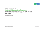
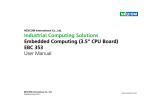
Impact-E 52
User Manual
(Issue B)
Part No: 85080839
Amplicon.com
IT and Instrumentation for industry
Sales: +44 (0) 1273 570 220 Website: www.amplicon.com Email: [email protected]
Introduction
The Impact-E range of rugged embedded computers has a small and compact chassis design. They are ideally suited to a variety of space-critical embedded
applications. Powered by Intel processors, these computers can provide the performance necessary for high speed and intensive tasks. Manufactured from
selected high quality components, the Impact-E series is a cost effective computing solution for use in harsh environments and critical 24/7 operations.
2
Amplicon.com
IT and Instrumentation for industry
Sales: +44 (0) 1273 570 220 Website: www.amplicon.com Email: [email protected]
Copyright
Installation Suggestions
Copyright © 2008 Amplicon Liveline Ltd.
All rights reserved. This publication, including all photographs, illustrations
and software, is protected under international copyright laws, with rights reserved.
No part of this manual may be reproduced, copied, translated or transmitted in any
form or by any means without the prior written consent from Amplicon Liveline Ltd.
Ensure you have a stable, clean working environment. Dust and dirt can get into
components and cause a malfunction. Use containers to keep small components
separated.
Adequate lighting and proper tools can prevent you from accidentally damaging
the internal components. Most of the procedures that follow require only a few
simple tools, including the following:
A Philips screwdriver
A flat-tipped screwdriver
A grounding strap
An anti-static pad
Using your fingers can disconnect most of the connections. It is
recommended that you do not use needlenose pliers to disconnect connections
as these can damage the soft metal or plastic parts of the connectors.
Acknowledgements
All product names or trademarks are properties of their respective owners.
Disclaimer
This instruction manual is supplied to provide the user with sufficient information
to utilise the purchased product in a proper and efficient manner. The information
contained has been reviewed and is believed to be accurate and reliable. However,
Amplicon Liveline Ltd accepts no responsibility for any problems caused by errors
and omissions. Specifications and instructions are subject to change without
notice.
The Impact-E 52 is RoHS compliant.
Handling Precautions
Always disconnect the unit from the power outlet whenever you are installing
or fixing a component inside the chassis.
If possible, always wear a grounded wrist strap when you are installing or
fixing a component inside the chassis. Alternatively, discharge any static electricity by touching the bare metal chassis of the unit case, or the bare metal
body of any other grounded appliance.
Hold electronic circuit boards by the edges only. Do not touch the components on the board unless it is necessary to do so. Do not flex or stress the
circuit board.
Use the correct screws and do not over tighten them.
3
Amplicon.com
IT and Instrumentation for industry
Sales: +44 (0) 1273 570 220 Website: www.amplicon.com Email: [email protected]
Keep the original packaging and static-protective bag in case the unit has to
be returned.
Table of Contents
Table of Contents
? Introduction.................................................................................................... 2
? 1.4 Board Layout ......................................................................................... 10
? Copyright ....................................................................................................... 3
Figure 1.2 Top View of the Impact-E 52 main board..................................... 10
? Acknowledgements ......................................................................................... 3
? 1.5 Dimension Drawing ............................................................................... 11
? Disclaimer ...................................................................................................... 3
Figure 1.3 : Dimension drawing of Impact-E 52 main board ........................ 11
? Installation Suggestions ................................................................................. 3
Figure 1.4 : Dimension drawing of Impact-E 52 chassis............................... 12
? RoHS Compliance .......................................................................................... 3
Chapter 2 Jumper Setting .............................................. 13
? Handling Precautions ..................................................................................... 3
? 2.1 Setting Jumpers ..................................................................................... 14
? Table of Contents............................................................................................ 4
Table 2.1 Setting Jumpers ............................................................................ 14
? 2.2 PCI Device interrupt and BUS Assignments ........................................... 14
? 2.3 Location of Jumpers .............................................................................. 15
Chapter 1 General Information ......................................... 6
Figure 2-1: Jumper Location of Impact-E 52 main board.............................. 15
? 1.1 Product Overview .................................................................................... 7
? 2.4 Definition of Jumpers ............................................................................ 16
? 1.2 Block Diagram ......................................................................................... 7
Figure 1.1 : Block Diagram of Impact-E 52 main board ................................. 7
? 1.3 Specifications .......................................................................................... 8
4
Amplicon.com
IT and Instrumentation for industry
Sales: +44 (0) 1273 570 220 Website: www.amplicon.com Email: [email protected]
Table of Contents
29
Appendix A-Watchdog Timer ........................................... 22929
? Watchdog Timer Common library ................................................................ 30
32
Appendix B-GPIO Programming Guide2 ............................... 2292
Appendix C-Power Consumption ...................................... 34
Appendix D-Installation Guide ......................................... 36
? D.1 Handling Precautions ............................................................................. 37
? D.2 Installation ............................................................................................. 38
1.Open Top Cover ......................................................................................... 38
2.Install/Remove CPU................................................................................... 38
3. Install/Remove RAM module .................................................................... 40
4.Close Top Cover ........................................................................................ 40
5.Open Bottom Cover ................................................................................... 40
6.Install HDD ............................................................................................... 41
7.Close Bottom Cover................................................................................... 41
Appendix E-Display Setting .............................................42
Appendix F-IEGD Installation Guide................................... 44
5
Amplicon.com
IT and Instrumentation for industry
Sales: +44 (0) 1273 570 220 Website: www.amplicon.com Email: [email protected]
Chapter 1 General Information
6
Amplicon.com
IT and Instrumentation for industry
Sales: +44 (0) 1273 570 220 Website: www.amplicon.com Email: [email protected]
Chapter 1 General Information
1.1 Product Overview
1.2 Block Diagram
Featuring Intel 945GME & ICH7 chipsets, the Impact-E 52 embedded computer
supports Intel’s Core 2 Duo /Celeron M processor with 533/667 MHz FSB
and DDR2 667/533 memory. This rugged fanless embedded computer is
designed for space-critical applications requiring extreme reliability, low-power
consumption and versatile I/O configuration. For added flexibility, this system
also boasts three RS232 ports, one RS232/422/485 port and two PCI expansion
slots.
Intel® Core 2 Duo,
Core Duo,Celeron M
533 / 667
MHz FSB
DDR2 Channel A
LVDS
Intel®
945GME
VGA
DDR2 DIMM Modules
DDR2 533 / 667 MHz
DDR2 Channel B
DDR2 Slot
DDR2 Slot
DVI Chrontel
7307
For data storage, the Impact-E 52 provides 1 x CompactFlash socket and 1 x 2.5"
HDD drive bay. The System supports ATX mode power feature and can accept a
wide range of power supplies from +12 V DC to +30 V DC.
4 Lanes
Front Panel
Internal Conn.
0/1
2,3/4/5
CF & IDE
Housed in a compact 195 mm x 268 mm x 101 mm heavy-duty aluminum chassis, the Impact-E 52 is designed for reliable, maintenance-free industrial computing. This fanless embedded computer offers a cost-effective solution for a
multitude of mission-critical embedded computing applications in automation,
machine control, and POS systems.
USB2.0
Intel®
ICH7-M DH
UltraDMA
33/66/100
SATA 1
SATA 2
1 x PCIe
Interface
2GB/s
PCIex1 Port (1)
PCI 32 Bit / 33 MHz Bus
SATA
Marvell
88E8053 GbE
RJ45
(LAN1)
Marvell
88E8053 GbE
RJ45
(LAN2)
PCI-Slot
ALC655
LPC BUS
KB/MS
IrDA
SIO1
SIO2
IT8712F
IT8712F
COM1,2
LPT
GPIO
COM3,4
? Supports Intel® Core 2 Duo / Core Duo/ Celeron® M processors
? Intel® 945GME Chipsets
Figure 1.1 : Block Diagram of Impact-E 52 main board
? Dual 1000/100/10Mbps LAN ports
? 6 x USB2.0, 1 x VGA, 1 x DVI, 4 x SIO
? 2 x PCI Expansion Slots
7
Amplicon.com
IT and Instrumentation for industry
Sales: +44 (0) 1273 570 220 Website: www.amplicon.com Email: [email protected]
Chapter 1 General Information
6SHFLÀFDWLRQV
I/O Interface-Front
Main Board
? HDD Access/Power/LAN status LEDs
? 2 x USB 2.0 ports
? ATX power on/off switch
? Supports Intel® Core 2 Duo, Core Duo, Celeron® M family processors with
533/667 MHz
I/O Interface-Rear
? Intel® Embedded Processor Reference List (Intel® Longevity CPU):
Core Duo Processor (T2300E) 1.66 G
Core Duo Processor (T2500) 2.0G
Celeron® M 530 1.73G
Celeron® M 440 1.86G
? 2 x PS/2 connectors (KB/MS)
? 1 x VGA connector
? 4 x USB 2.0 ports
Chipset
? 2 x GbE LAN Ports
? Intel® 945GME Graphics Memory Controller Hub (GMCH)
? Intel® 82801 GBM ICH7 Mobile digital Home (ICH7-M)
? 4 x Serial Ports, with 1x DB44 connector ( Three ports support RS232, One
port supports RS232/422/485)
Main Memory
? 1 x DVI interface
? 2 x 240 pin DDR2 533/667 DIMM sockets, up to 2 GB unbuffered non-ECC
DDR SDRAM (Max. 3G Capacity supported)
? 1 x Mic-in and 1 x Speaker-out
? 1 x 2-pin connector output for remote power on/off switch
Expansion Slot
? DC-in power connector for +12V to +30V DC power input
? Supports 2 x 32-bit/ 33MHz PCI card
Device
? PCI Length support:
1 slot x 160 mm, and 1 slot x 240mm (When 2.5" HDD installed)
2 slots x 240 mm (When no HDD is installed)
? 1 x On-board CompactFlash socket
? 1 x Internal 2.5" HDD drive bay
NB: The Impact-E 52 does not support -12V PCI cards as standard. For this
support a '-12V PCI card module' is required. This module will enable support
for -12V PCI cards in one PCI slot only, not both.
8
Amplicon.com
IT and Instrumentation for industry
Sales: +44 (0) 1273 570 220 Website: www.amplicon.com Email: [email protected]
Chapter 1 General Information
Power Input
? DC to DC power designed for on-board support of 12 to 30 VDC
(Max: 120 Watts)
? 1 x External 120 W AC adapter
Power input: 100 to 240 V AC, 2A, 50/60 Hz
Power output: 19 VDC
Dimensions
? 195 mm (W) x 268 mm (D) x 101 mm (H) (7.6" x 10.5" x 4.0")
Construction
? Aluminum chassis with fanless design
Environment
? Operating temperature:
Ambient with air flow : 0°C to 40°C (CPU loading: 70% less continently)
? Tcase ( Surface Temperature of Chassis)
5°C to 50°C (with hard disk drive)
-10°C to 55°C (with CF card or solid state drive)
? Storage temperature: -20°C to 80°C
Relative humidity: 10% to 90% (Non-condensing)
9
Amplicon.com
IT and Instrumentation for industry
Sales: +44 (0) 1273 570 220 Website: www.amplicon.com Email: [email protected]
Chapter 1 General Information
1.4 Board Layout
Figure 1.2 : Top View of the Impact-E 52 main board
10
Amplicon.com
IT and Instrumentation for industry
Sales: +44 (0) 1273 570 220 Website: www.amplicon.com Email: [email protected]
Chapter 1 General Information
1.5 Dimension Drawing
Figure 1.3 : Dimension drawing of Impact-E 52 main board
11
Amplicon.com
IT and Instrumentation for industry
Sales: +44 (0) 1273 570 220 Website: www.amplicon.com Email: [email protected]
Chapter 1 General Information
Figure 1.4 Dimension drawing of the Impact-E 52 chassis
12
Amplicon.com
IT and Instrumentation for industry
Sales: +44 (0) 1273 570 220 Website: www.amplicon.com Email: [email protected]
Chapter 2 Jumper Setting
13
Amplicon.com
IT and Instrumentation for industry
Sales: +44 (0) 1273 570 220 Website: www.amplicon.com Email: [email protected]
Chapter 2 Jumper Setting
2.1 Setting Jumpers
2.2 PCI Device interrupt and BUS Assignments
A jumper is the simplest kind of electric switch. It consists of two metal pins and
a cap. When setting the jumpers, ensure that the jumper caps are placed on the
correct pins. When the jumper cap is placed on both pins, the jumper is SHORT.
If you remove the jumper cap, or place the jumper cap on just one pin, the
jumper is OPEN. Please see the following illustrations
The illustrations on the right show
a 2-pin jumper. When the jumper
cap is placed on both pins, the
jumper is SHORT. If you remove
the jumper cap, or place the
jumper cap on just one pin, the
Open (Off)
jumper is OPEN.
Configuration
BUS/DEVICE/FUNCTION
PCI slot
PCI-E slot
Short (On)
These illustrations show a
3-pin Jumper. Pins 1 and 2 are
SHORT.
Table 2.1 Setting Jumpers
14
Amplicon.com
IT and Instrumentation for industry
Sales: +44 (0) 1273 570 220 Website: www.amplicon.com Email: [email protected]
1 / 17 / 0
1 / 18 / 0
PCI INT#
REQ# /GNT#
A,B,C,D
D,A,B,C
0,1
Chapter 2 Jumper Setting
2xUSB
(USB1)
1
6
-12V input (J10)
1
FAN(CN4)
PCI (CN5)
SATA(J6) 1
1
SATA(J7)
7
PCI-E Slot (CN8)
7
LED1
PS2 for Mouse(KM1)
VGA
(CN10)
8
1
USB(J3)
1
2.3 Location of Jumpers
21
B2
B1
A1
A2
PS2 for Keyboard(KM2)
1 x LAN TOP)
2 x USB (Bot)
(CON1)
LED2
LED3
South
Bridge
CPU
1 x LAN TOP)
2 x USB (Bot)
(CON2)
Compact Flash
(CN9)
DIMM2
DIMM1
1
1
1 1
1
1
1
1
SW2
JP6
JP7
JP5
1
1
1
4 x COM
(J12)
IDE (CN6)
1
FAN(J1)
1
DC Power Output Conn. (J8)
1
1
FAN(J2) 1
ATX Switch
(SW1)
1
2
1
1
JP2
DVI(CN1)
DC-IN
(CN11)
2 LVDS (CN2)
1
2 LVDS (CN3)
1
1 JP4
1
CCFL(J4)
ATX Remote
Switch (JP12)
1
1
JP3
Figure 2-1: Jumper Location of Impact-E 52 main board
15
Amplicon.com
Line Out (Top)
MIC In (Bot)
(U42)
CD-IN
(JP11)
1
IT and Instrumentation for industry
Sales: +44 (0) 1273 570 220 Website: www.amplicon.com Email: [email protected]
JP9
JP10
JP8 GPIO(J11)
North
Bridge
1
2
1
14
PIO(CN7)
1
1
1
1
Chapter 2 Jumper Setting
'HÀQLWLRQRI-XPSHUV
? JP5: I2C (1x2 pin header,2.54mm)
? JP2: ATX power Switch (1x4 pin header,2.54mm)
4
2 1
1
PIN
Def.
PIN
Def.
PIN
Def.
1
ATX Power on
2
ATX Power on
3-4
GND
Pin
Def.
Pin
Def.
2
Data
1
CLK
? JP6: CMOS Status Select (1x3 pin header,2.54mm)
? JP3: Hardware Reset (1x2 pin header,2.54mm)
3
2 1
1
PIN
Def.
PIN
Def.
Pin
Status
Function
1
Reset
2
GND
1-2
Short*
Normal Operation
2-3
Short
Clear CMOS DATA
? JP4:Panel Power Select (1x3 pin header,2.54mm)
3
? JP7: CF Master / Slave Selection (1x3 pin header,2.54mm)
1
3
PIN
Def.
1
VCC5
2
Panel Power
3
VCC3
<1-2 pin short= Master / **2-3 pin short= Slave>
16
Amplicon.com
1
IT and Instrumentation for industry
Sales: +44 (0) 1273 570 220 Website: www.amplicon.com Email: [email protected]
PIN
Def.
PIN
Def.
PIN
Def.
3
Slave (GND)
2
CF_CSEL
1
Master (VCC5)
Chapter 2 Jumper Setting
? SW2: COM2 RS232/422/485 Select (2x10 DIP SWITCH)
O
N
? JP8: GPI/O Programming LED (2x2 pin header,2.0mm)
1
2
3
4
5
6
7
8
9
0
3 1
Mode
4 2
Pin
Def.
Pin
Def.
3
GP21
1
GP20
4
GND
2
GND
2
3
4
5
6
7
8
9
10
RS232* OFF
OFF
OFF
ON
OFF
ON
OFF
OFF
OFF
OFF
RS422
OFF
OFF
ON
OFF
ON
OFF
ON
ON
ON
ON
RS485
ON
ON
OFF
ON
ON
OFF
OFF
OFF
OFF
ON
? JP11: CD-IN (1x4 pin header, 2.54mm)
? JP9: IR Interface (1x5 pin header,2.54mm)
4
PIN Def.
PIN
Def.
PIN
Def.
PIN
Def.
PIN
Def.
5
4
GND
3
IRRX
2
CIRRX
1
VCC5
? JP10: RI# Signal Power Select (1x5 pin header,2.54mm)
1
5
<1-2 short: RI Power = 5v / 3-4 short: RI Power=12V / **4-5 short: Normal >
PIN Def.
PIN
Def.
PIN
Def.
PIN
Def.
PIN
Def.
5
4
RI2
3
+12V
2
RI2
1
VCC5
SP_RI2
17
Amplicon.com
1
1
5
IRTX
1
IT and Instrumentation for industry
Sales: +44 (0) 1273 570 220 Website: www.amplicon.com Email: [email protected]
Pin.
Def.
1
CD-IN-L
2
AUDIO GND PWR
3
AUDIO GND PWR
4
CD-IN-R
Chapter 2 Jumper Setting
? CN4:CPU FAN (1x4 pinWafer, 2.54mm)
4
1
Pin.
Def.
1
GND
2
+12V
3
SENSE
4
FAN_CTRL
? J1/J2: SYSTEM FAN ( 1x 3 pin Wafer, 2.54mm)
3
1
Pin.
Def.
1
GND
2
12V
3
SENSE
18
Amplicon.com
IT and Instrumentation for industry
Sales: +44 (0) 1273 570 220 Website: www.amplicon.com Email: [email protected]
Chapter 2 Jumper Setting
? CN2/CN3: LVDS Connector (2x10 pin DF13)
? CN1: DVI Interface (2x17 pin box header, 2.0mm)
34
17
2
1
Pin.
Def.
Pin.
Def.
1
CAS_GND
18
HPDET
2
CAS_GND
19
DVI_DATA0#
3
DVI_DATA2#
20
DVI_DATA0
4
DVI_DATA2
21
CAS_GND
5
GND
22
NC
6
NC
23
NC
7
NC
24
GND
8
DDC_CLK
25
TLC
9
DDC_DATA
26
TLC#
10
NC
27
GND
11
DVI_DATA1#
28
GND
12
DVI_DATA1
29
NC
13
CAS_GND
30
NC
14
NC
31
NC
15
NC
32
CAS_GND
16
DVI_VCC
33
CAS_GND
17
CAS_GND
34
NC
IT and Instrumentation for industry
Sales: +44 (0) 1273 570 220 Website: www.amplicon.com Email: [email protected]
2
19
1
CN2
Pin.
Def.
Pin.
Def.
1
DDCCLK
11
LA_CLK_P
2
DDC_DATA
12
LA_DATAN1
3
VDD
13
LA_CLK_N
4
LA_DATAP0
14
GND
5
NC
15
GND
6
LA_DATAN0
16
BACKLIGNT
7
NC
17
LA_DATAP2
8
VDD
18
BACKLIGNT
9
GND
19
LA_DATAN2
10
LA_DATAP1
20
GND
Pin.
Def.
Pin.
Def.
1
DDCCLK
11
LB_CLK_P
2
DDC_DATA
12
LB_DATAN1
3
VDD
13
LB_CLK_N
4
LB_DATAP0
14
GND
5
NC
15
GND
CN3
19
Amplicon.com
20
Chapter 2 Jumper Setting
6
LB_DATAN0
16
BACKLIGNT
16
Clock0
+5V
7
NC
17
LB_DATAP2
17
GND
Grant#0
8
VDD
18
BACKLIGNT
18
Request#0
GND
9
GND
19
LB_DATAN2
19
+5V
Power Management Event#
10
LB_DATAP1
20
GND
20
Address and Data 31
Address and Data 30
21
Address and Data 29
+3.3V
22
GND
Address and Data 28
23
Address and Data 27
Address and Data 26
24
Address and Data 25
GND
? CN5: PCI-SLOT (Standard PCI 32 Bit Connector)
B1
A1
Pin.
Def. ( Side B)
Def. ( Side A)
25
+3.3V
Address and Data 24
1
-12V
GND
26
Command & Byte Enable#3
Initialization Device Select
2
GND
+12V
27
Address and Data 23
+3.3V
3
GND
+5V
28
GND
Address and Data 22
4
NC
+5V
29
Address and Data 21
Address and Data 20
5
+5V
+5V
30
Address and Data 19
GND
6
+5V
Interrupt A#
31
+3.3V
Address and Data 18
7
Interrupt B#
Interrupt C#
32
Address and Data 17
Address and Data 16
8
Interrupt D#
+5V
33
Command & Byte Enable#2
+3.3V
9
Connector capacitance 10pf to Ground
NC
34
GND
Frame#
10
Request#1
+5V
35
Initiator Ready#
GND
11
Connector capacitance 10pf to Ground
NC
36
+3.3V
Target Ready#
12
GND
GND
37
Device Select#
Device Select#
13
GND
GND
38
GND
GND
14
Clock1
Grant#1
39
Lock#
Lock#
15
GND
Reset#
40
Parity Error#
Parity Error#
20
Amplicon.com
IT and Instrumentation for industry
Sales: +44 (0) 1273 570 220 Website: www.amplicon.com Email: [email protected]
Chapter 2 Jumper Setting
? CN7: Parallel port (2x13 pin box header)
41
+3.3V
+3.3V
42
System Error#
System Error#
43
+3.3V
+3.3V
44
Command & Byte Enable#1
Command & Byte Enable#1
Pin.
Def.
Pin.
Def.
45
Address and Data 14
Address and Data 14
1
STB#
14
AFD-
46
GND
GND
2
PD0
15
ERR-
47
Address and Data 12
Address and Data 12
3
PD1
16
INIT-
48
Address and Data 10
Address and Data 10
4
PD2
17
NC
49
GND
GND
5
PD3
18
GND
50
Connector Key
Connector Key
6
PD4
19
GND
51
Connector Key
Connector Key
7
PD5
20
GND
52
Address and Data 8
Address and Data 8
8
PD6
21
GND
53
Address and Data 7
Address and Data 7
9
PD7
22
GND
54
+3.3V
+3.3V
10
ACK-
23
GND
55
Address and Data 5
Address and Data 5
11
BUSY
24
GND
56
Address and Data 3
Address and Data 3
12
PE
25
GND
57
GND
GND
13
SLCT
26
NC
58
Address and Data 1
Address and Data 1
59
+5V
+5V
60
+5V
+5V
61
+5V
+5V
62
+5V
+5V
13
26
NB: The Impact-E 52 does not support -12V PCI cards as standard. For this
support a '-12V PCI card module' is required. This module will enable support
for -12V PCI cards in one PCI slot only, not both.
21
Amplicon.com
IT and Instrumentation for industry
Sales: +44 (0) 1273 570 220 Website: www.amplicon.com Email: [email protected]
1
14
Chapter 2 Jumper Setting
? CN8: PCI-E Slot
? CN9: Compact Flash Socket (Type 2)
B2
B1
A1
A2
Pin.
Def. ( Side B)
Def. ( Side A)
1
+12 volt power
NC
2
+12 volt power
+12 volt power
Pin.
Def.
Pin.
Def.
3
Reserved
+12 volt power
1
GND
2
SDD3A
4
Ground
Ground
3
SDD4A
4
SDD5A
5
SMBus clock
NC
5
SDD6A
6
SDD7A
6
SMBus data
NC
7
SDCS#1
8
GND
7
Ground
NC
9
GND
10
GND
8
+3.3 volt power
NC
11
GND
12
GND
9
NC
3.3v volt power
13
VCC
14
GND
10
3.3VSB
3.3v volt power
15
GND
16
GND
11
WAKE#
PE_RESEET#
17
GND
18
SDA2A
12
Reserved
Ground
19
SDA1A
20
SDA0A
13
Ground
REFCLK_P
21
SDD0A
22
SDD1A
14
TXP0
REFCLK_N
23
SDD2A
24
NC
15
TXN0
Ground
25
CF_CD2#
26
CF_CD1#
16
Ground
RXP0
27
SDD11A
28
SDD12A
17
SDVO_CTRLCLK
RXN0
29
SDD13A
30
SDD14A
18
Ground
Ground
31
SDD15A
32
SDCS#3
33
NC
34
SDIOR#
35
SDIOW#
36
VCC
22
Amplicon.com
IT and Instrumentation for industry
Sales: +44 (0) 1273 570 220 Website: www.amplicon.com Email: [email protected]
Chapter 2 Jumper Setting
37
HDIRQ14
38
VCC
25
IOR
26
GND
39
CF_SEL#
40
NC
27
IO_CH_RDY
28
DIAG
41
IDERST#
42
SIORDY
29
DACK#,
30
GND
43
SDREQ
44
SDDACK#
31
IRQ_R
32
NC
45
IDEACTP#
46
DIAG#
33
DA1
34
66DET
47
SDD8A
48
SDD9A
35
DA0
36
DA2
49
SDD10A
50
GND
37
CS0
38
CS1
39
ACT
40
GND
? CN12(Reverse)/ CN6 (Obverse): IDE Connector (2x44 pin box header,2.0mm)
41
VCC5
42
VCC5
<Note: CN12 and CN6 are co-layout>
43
GND
44
NC
41
VCC5
42
VCC5
43
GND
44
NC
1
2
43
44
Pin.
Def.
Pin.
Def.
1
RESET
2
GND
3
DD7
4
DD8
5
DD6
6
DD9
7
DD5
8
DD10
9
DD4
10
DD11
11
DD3
12
DD12
13
DD2
14
DD13
15
DD1
16
DD14
17
DD0
18
DD15
19
GND
20
NC
21
REQ
22
GND
23
IOW
24
GND
? CN10: VGA Port (2x8 pin box header, 2.0mm)
23
Amplicon.com
IT and Instrumentation for industry
Sales: +44 (0) 1273 570 220 Website: www.amplicon.com Email: [email protected]
1
2
15
16
Pin.
Def.
Pin.
Def.
1
RED_VGA
9
VGA_VCC
2
GREEN_VGA
10
GND
3
BLUE_VGA
11
NC
4
NC
12
DATA_V
5
GND
13
HS_VGA
6
GND
14
VS_VGA
7
GND
15
CLK_V
8
GND
16
NC
Chapter 2 Jumper Setting
? CN11: Power Jack 4 pins
? J8: DC Power output Connector (1x4-pin power jack, 5.08mm)
4
Pin
Def,
Pin
Def,
3-4
GND
1-2
DC-IN
? J3: Internal USB Connector ( 1x6 pin JST, 2.0mm)
Pin.
Def.
Pin.
Def.
Pin.
Def.
Pin.
Def.
4
VCC5
3
GND
2
GND
1
+12v
? J10: External 12 power input connector (1x2 pin JST, 2.5mm)
1
6
1
1
Pin.
Def.
Pin.
Def.
1
VCC
4
USB_1N
2
USB_0N
5
USB_1P
3
USB_0P
6
GND
Pin.
Def.
Pin.
Def.
2
GND
1
-12V
? J11: External GPI/O Indicated LED (2x5 pin header, 2.0mm)
? J4: CCFL (1x7 pin JST, 2.54mm)
9
10
1
7
1
2
Pin.
Def.
Pin.
Def.
Pin.
Def.
Pin.
Def.
1
+5V
2
+12V
1
+5V
2
GND
3
+12V
4
Brightness Ctrl
3
GP20: Output
4
GP24: Input
5
GND
6
GND
5
GP21: Output
6
GP25: Input
7
Backlight Enable
7
GP22: Output
8
GP26: Input
9
GP23: Output
10
GP27: Input
24
Amplicon.com
IT and Instrumentation for industry
Sales: +44 (0) 1273 570 220 Website: www.amplicon.com Email: [email protected]
Chapter 2 Jumper Setting
? J6/J7: SATA Connector (Standard Serial ATAII 1.27mm connector)
7
? CON1/ CON2: USB / LAN Port (RJ45 Jack combine with dual USB ports)
1
J6
Pin.
Def.
Pin.
Def.
1
GND
2
TXP0
4
GND
3
TXN0
7
GND
5
RXN0
6
RXP0
CON1-A:
J7
Pin.
Def.
Pin.
Def.
1
GND
2
TXP1
4
GND
3
TXN1
7
GND
5
RXN1
6
RXP1
Def.
Pin.
Def.
1
VCC
5
VCC
2
USB_2N
6
USB_3N
3
USB_2P
7
USB_3P
4
GND
8
GND
9
TX0P_E
19
VCC3
10
TX0N_E
20
LINK_E
11
TX1P_E
21
GND
12
TX2P_E
22
GND
13
TX2N_E
23
GND
14
TX1N_E
24
GND
15
TX3P_E
25
GND
16
TX3N_E
26
GND
17
ACT_E
27
GND
18
LINK_E
28
GND
CON1-B:
25
Amplicon.com
Pin.
IT and Instrumentation for industry
Sales: +44 (0) 1273 570 220 Website: www.amplicon.com Email: [email protected]
Chapter 2 Jumper Setting
? J12: Serial Interface ( COM1~COM4, 44-pin D-SUB)
CON2-A:
Pin.
Def.
Pin.
Def.
1
VCC
5
VCC
2
USB_4N
6
USB_5N
3
USB_4P
7
USB_5P
4
GND
8
GND
9
TX0P_F
19
VCC3
10
TX0N_F
20
LINK_F
11
TX1P_F
21
GND
12
TX2P_F
22
GND
13
TX2N_F
23
GND
14
TX1N_F
24
GND
15
TX3P_F
25
GND
16
TX3N_F
26
GND
17
ACT_F
27
GND
18
LINK_F
28
GND
COM1 (RS-232)
CON2-B:
GreenUpper
Line-Out
MIC-In
26
Amplicon.com
Pin.
Def.
1
DCD1
2
RXD1
3
TXD1
4
DTR1
5
GND
6
DSR1
7
RTS1
8
CTS1
9
RI1
10
GND
Pin.
Def.
Pin.
Def.
11
DCD2
12
RXD2
13
TXD2
14
DTR2
15
GND
16
DSR2
17
RTS2
18
CTS2
19
RI2
20
GND
Pin.
Def.
Pin.
Def.
21
DCD3
22
RXD3
23
TXD3
24
DTR4
25
GND
26
DSR3
27
RTS3
28
CTS3
29
RI3
30
GND
COM3 (RS-232)
Def.
Pink Lower
Def.
COM2 (RS-232)
? U42: Audio Interface (Double layer Phone jack)
Def.
Pin.
IT and Instrumentation for industry
Sales: +44 (0) 1273 570 220 Website: www.amplicon.com Email: [email protected]
Chapter 2 Jumper Setting
COM4 (RS-232)
19
Power Source
20
Reserved
Pin.
Def.
Pin.
Def.
31
DCD4
32
RXD4
33
TXD4
34
DTR5
35
GND
36
DSR4
37
RTS4
38
CTS4
39
RI4
40
GND
KM2 For Keyboard:
41
NC
42
NC
Pin.
Def.
Pin.
Def.
43
NC
44
NC
1
KB_DATA
2
NC
3
GND
4
KM_VCC
5
KB_CLK
6
NC
Pin.
Def.
Pin.
Def.
1
LM_DATA
2
NC
? KM1/ KM2 :P/S 2 Keyboard / Mouse ( 6-pin Mini DIMM )
COM2 (RS-422)
Pin.
Def.
Pin.
Def.
11
TXD#
12
TXD
13
RXD
13
RXD#
15
GND
16
RTS
17
RTS#
18
CTS
3
GND
4
KM_VCC
19
CTS#
20
GND
5
LM_CLK
6
NC
KM1 For Mouse:
COM2 (RS-485) :pin 19 is defined as an external Power source, which can be
? JP12: ATX Remote On / Off Switch ( 2 pin Tterminal port, 3.81mm)
selected for 5V or 12V by JP10
Pin.
Def.
Pin.
Def.
11
TXD#
12
TXD
RXD#
RXD
13
Reserved
13
Reserved
Pin.
Def.
15
Reserved
15
Reserved
1
GND
17
Reserved
17
Reserved
2
PWR_ON
27
Amplicon.com
IT and Instrumentation for industry
Sales: +44 (0) 1273 570 220 Website: www.amplicon.com Email: [email protected]
Chapter 2 Jumper Setting
? USB1: USB Port (Dual USB port)
Pin.
Def.
Pin.
Def.
1
VCC
5
VCC
2
USB_1N
6
USB_0N
3
USB_1P
7
USB_0P
4
GND
8
GND
28
Amplicon.com
IT and Instrumentation for industry
Sales: +44 (0) 1273 570 220 Website: www.amplicon.com Email: [email protected]
Appendix A-Watchdog Timer
29
Amplicon.com
IT and Instrumentation for industry
Sales: +44 (0) 1273 570 220 Website: www.amplicon.com Email: [email protected]
Appendix-A Watchdog Timer
Watchdog Timer Common library
===============================================================
0
SetupWDT
PROC
1
mov
al,87h
2
out
2eh, al
3
mov
al,01h
4
out
2eh,al
5
mov
al,55h
6
out
2eh,al
7
out
2eh,al
9
mov
al,07h
10
out
2eh,al
11
mov
al,07h
12
out
2fh,al
13
ret
8
14
SetupWDT
ENDP
===============================================================
0
InitWDT
PROC
1
mov
al,71h
2
out
2eh,al
3
mov
al,30h
4
out
2fh,al
5
30
Amplicon.com
IT and Instrumentation for industry
Sales: +44 (0) 1273 570 220 Website: www.amplicon.com Email: [email protected]
Appendix-A Watchdog Timer
6
mov
al,72h
7
out
2eh,al
8
mov
al,0c0h -Here!! set 0c0h
for second, set 40h for
minute
9
out
2fh,al
10
ret
11
InitWDT
ENDP
===============================================================
0
SetWDTTime
PROC
1
mov
al,73h
2
out
2eh,al
3
mov
al,5-Here!! Set 5 sec. (time out vale: 0x00-0xff)
4
out
2fh,al
5
ret
6
SetWDTTime ENDP
===============================================================
0
ExitSetup
PROC
1
mov
al,02h
2
out
2eh,al
3
mov
al,02h
4
out
2fh,al
5
ret
6
ExitSetup
ENDP
31
Amplicon.com
IT and Instrumentation for industry
Sales: +44 (0) 1273 570 220 Website: www.amplicon.com Email: [email protected]
Appendix B-GPIO Programming Guide
32
Amplicon.com
IT and Instrumentation for industry
Sales: +44 (0) 1273 570 220 Website: www.amplicon.com Email: [email protected]
Appendix-B GPIO Programming Guide
PIN
Description
PIN
Description
1
+5V
2
GND
3
GP20:OUTPUT
4
GP24:INPUT
5
GP21:OUTPUT
6
GP25:INPUT
7
GP22:OUTPUT
8
GP26:INPUT
9
GP23:OUTPUT
10
GP27:INPUT
*If GPIO slave input port: Reflects the incoming logic levels of the pins, regardless of whether the pin is defined as an input or output. Writes to this
register[bit:7..4] have no effect.
*If GPIO slave output port: Controls the levels of the GPIO output pins defined
as outputs. Bit values in this register[bit:3..0] have no effect on pins defined as
inputs.
Read form this register reflects the saved value last written, not the actual pin
value.
IO ADDRESS : 801H
Bit0 : GP20
Bit1 : GP21
Bit2 : GP22
Bit3 : GP23
Bit4 : GP24
Bit5 : GP25
Bit6 : GP26
Bit7 : GP27
Note:
•
GPIO Pin-20 signal level is controlled by BIOS, high defined as system
power up and low defined as system shutdown with standby power.
33
Amplicon.com
IT and Instrumentation for industry
Sales: +44 (0) 1273 570 220 Website: www.amplicon.com Email: [email protected]
Appendix C-Power Consumption
34
Amplicon.com
IT and Instrumentation for industry
Sales: +44 (0) 1273 570 220 Website: www.amplicon.com Email: [email protected]
Appendix C Power Consumption
DC Line 19V: (System-Only)
CPU Type: Intel Core Duo T2500 2.0GHz
+19V
Total Watts
Full-Loading Mode
2.61A
49.59W
Idle Mode
1.12A
21.28W
Standby Mode (HDD Power-Down)
1.07A
20.33W
Test Criteria:
? Test configuration should include a fully configured system with test board, memory and hard disk drive.
? Full loading mode should utilise the CPU 100% by running a Burn-in test program.
? Idle mode should utilise the CPU loading below 5%, and there should be no data or application running.
35
Amplicon.com
IT and Instrumentation for industry
Sales: +44 (0) 1273 570 220 Website: www.amplicon.com Email: [email protected]
Appendix D- Installation Guide
36
Amplicon.com
IT and Instrumentation for industry
Sales: +44 (0) 1273 570 220 Website: www.amplicon.com Email: [email protected]
Appendix D- Installation Guide
D.1 Handling Precautions
? Always disconnect the unit from the power outlet whenever you are installing
or fixing a component inside the chassis.
? If possible, always wear a grounded wrist strap when you are installing or
fixing a component inside the chassis. Alternatively, discharge any static electricity by touching the bare metal chassis of the unit case, or the bare metal
body of any other grounded appliance.
? Hold electronic circuit boards (such as this main board) by the edges only.
Do not touch the components on the board unless it is necessary to do so. Do
not flex or stress the circuit board.
? Use the correct screws and do not over tighten them.
? Keep the original packaging and static-protective bag in case the unit has to
be returned.
37
Amplicon.com
IT and Instrumentation for industry
Sales: +44 (0) 1273 570 220 Website: www.amplicon.com Email: [email protected]
Appendix D- Installation Guide
D.2 Installation
2.Install/Remove CPU
1.Open Top Cover
? Step 2-1: Unscrew 6 screws on heat sink
? Step 1-1: Remove 6 screws from the top.
? Step 2-2: Pay attention to CPU installation
38
Amplicon.com
IT and Instrumentation for industry
Sales: +44 (0) 1273 570 220 Website: www.amplicon.com Email: [email protected]
Appendix D- Installation Guide
? Step 2.3: Be aware that the beveled corner of the CPU as shown in the picture
is aligned to the direction of the socket.
? Step 2.4: Secure the CPU and apply heat sink silicon compound
? Step 2.5: Lock the heat sink in place
39
Amplicon.com
IT and Instrumentation for industry
Sales: +44 (0) 1273 570 220 Website: www.amplicon.com Email: [email protected]
Appendix D- Installation Guide
3. Install/Remove RAM module
5.Open Bottom Cover
? Step 3-1: Insert either 1 or 2 DDR
? Step 5-1: Remove the screws on the bottom of the chassis
4.Close Top Cover
? Step 4-1: Secure the top cover with screws
40
Amplicon.com
IT and Instrumentation for industry
Sales: +44 (0) 1273 570 220 Website: www.amplicon.com Email: [email protected]
Appendix D- Installation Guide
6.Install HDD
7.Close Bottom Cover
? Step 6-1: Unscrew HDD stand and secure 2.5" HDD
? Step7-1: Lock bottom cover with screws
? Step 6-2: Place finished stand with HDD back to the chassis and make sure it
is properly secured. Plug in HDD cable and make sure SATA power cable
and SATA cable are in the right positions.
41
Amplicon.com
IT and Instrumentation for industry
Sales: +44 (0) 1273 570 220 Website: www.amplicon.com Email: [email protected]
Appendix E- Display Setting
42
Amplicon.com
IT and Instrumentation for industry
Sales: +44 (0) 1273 570 220 Website: www.amplicon.com Email: [email protected]
Appendix D- Installation Guide
? Select "Monitor" from Display Devices
Since the chipset belongs to Intel mobile group, LVDS is the display default.
If VGA port is not linked to a monitor when the system is powered on, LVDS
will be the first display automatically afterwards. Follow the steps below to
select the VGA/DVI monitor as the default display.
After setting, press "CRTL + ALT + F1" to enable monitor as the main display if
have the same situation.
? Have Impact-E system linked with VGA/DVI monitor
? Select "Intel GMA Driver for Mobile" from Control Panel
? Select "Enable Hot Keys" from Hot Keys
43
Amplicon.com
IT and Instrumentation for industry
Sales: +44 (0) 1273 570 220 Website: www.amplicon.com Email: [email protected]
Appendix F- IEGD Installation Guide
44
Amplicon.com
IT and Instrumentation for industry
Sales: +44 (0) 1273 570 220 Website: www.amplicon.com Email: [email protected]
Appendix D- Installation Guide
How to resolve no display:
? Step 3: Uncompress the IEGD driver and run setup.exe in the utility folder.
If there is no monitor attached onto the VGA connector when the system is at
startup stage, the chipset will disable the VGA signal output automatically.
\IEGD_8_0_Windows-For A2DVI2\IEGD_8_0_Windows\IEGD_8_0_Windows\Utilities
The IEGD VGA driver can help to resolve no display issue in Windows XP and
XPe OS. Please follow this IEGD driver installation guide:
? Step 1: Remove original graphic driver under Windows XP or Windows XPe.
? Step 2: After reboot, please set “Boot Display” to be “CRT+DVI” in the
BIOS setting.
45
Amplicon.com
IT and Instrumentation for industry
Sales: +44 (0) 1273 570 220 Website: www.amplicon.com Email: [email protected]
Appendix D- Installation Guide
? Step-4: After driver installation, please reboot the system.
? Step-6: Select preferred Display Config:
? Step-5: Press “Advanced” in Display Properties.
945_DVI (single)
945_CRT (single)
945_DVI, 945_CRT (twin)
945_DVI (clone) 945_CRT
945_DVI (extend) 945_CRT
46
Amplicon.com
IT and Instrumentation for industry
Sales: +44 (0) 1273 570 220 Website: www.amplicon.com Email: [email protected]