1
GRAPHOLAS 12.1
USER MANUAL
28.03.2013
Grapholas 12.1
© Copyright 2013
Esko-Graphics Imaging GmbH, 25524 Itzehoe, Germany
All rights reserved. This document and the information and instructions contained therein is the property
of Esko-Graphics. These documents contain the product descriptions according to their current state at
the time of publication, subject to confirmation. No guarantees are granted or expanded upon by this
document. Furthermore, Esko-Graphics will not guarantee for illustrations relating to the usage of the
products or for results from using the software or the use of the information contained herein. EskoGraphics is not responsible for direct or indirect damages or damages caused as logical consequence or
latent damages resulting from the use of the software or from the impossibility of using the software or of
the information contained herein.
The technical data contained herein and the content of this manual is subject to change without prior
notification. Revisions may be issued from time to time that inform of such changes and/or supplements.
No part of this document may be reproduced, transferred, electronically stored or published, irrespective
of the reasons without written permission and irrespective of the method or means used, i. e., electronic,
mechanical, by printing, microfiche, etc.
These documents replace all previous versions.
Grapholas® is a registered trademark of Esko-Graphics Imaging GmbH.
Cyrel®, Cyrel® Digital Imaging System and Cyrel® Digital Imager (CDI) are registered trademarks of
DuPont.
Microsoft and the Microsoft Logo are registered trademarks of Microsoft Corporation in the USA and
other countries.
The software from Esko-Graphics may contain the "RSA Data Security, Inc. MD5 Message-Digest
Algorithm".
JDF and the JDF Logo are trademarks of the CIP4-Organisation. Copyright 2001 The International
Cooperation for the Integration of Processes in Prepress, Press and Postpress (CIP4). All rights
reserved.
Java and all Java-based trademarks and logos are trademarks or registered trademarks of Sun
Microsystems in the U.S. and/or other countries.
Some parts of this software use technologies of JGoodies, Barbecue (Copyright 2003, International
Barcode Consortium), and Jakarta (licensed by Apache: www.apache.org/licenses/LICENSE-2.0.txt).
All other product names are trademarks or registered trademarks of their respective owners.
2
Grapholas 12.1
Table of Contents
1
IMPORTANT NOTE ...................................................................................................................................... 6
2
SYSTEM REQUIREMENTS ............................................................................................................................. 7
3
GRAPHOLAS SERVICE .................................................................................................................................. 8
1.
ANTIVIRUS SOFTWARE ON CDI MACHINES .................................................................................................. 9
4
FIRST START-UP OF THE SOFTWARE .......................................................................................................... 10
4.1
ENTERING THE LICENSE KEY ............................................................................................................................... 10
4.2
SETTING THE LANGUAGE ................................................................................................................................... 10
5
MANAGING DATA SOURCES ...................................................................................................................... 11
5.1
ADDING A LOCAL DATA SOURCE ......................................................................................................................... 11
5.2
ADDING AN FTP DATA SOURCE.......................................................................................................................... 12
5.3
CHANGING AN ENTRY ....................................................................................................................................... 13
5.4
DELETING AN ENTRY ........................................................................................................................................ 13
5.5
SAVING SETTINGS ............................................................................................................................................ 13
6
WORKING WITH INTERCHANGEABLE LENSES (OPTIONAL)......................................................................... 14
6.1
STARTING THE SERVICE ..................................................................................................................................... 14
6.2
CHANGING TO ANOTHER PROFILE ....................................................................................................................... 14
7
ADJUSTING THE "MERGER" USER INTERFACE ............................................................................................ 15
7.1
PASSWORD-PROTECTING FUNCTIONS .................................................................................................................. 15
7.2
CHANGING THE PASSWORD ............................................................................................................................... 16
7.3
ENTERING A PASSWORD TO CHANGE SETTINGS ..................................................................................................... 16
8
MERGER .................................................................................................................................................... 17
8.1
QUICK START.................................................................................................................................................. 17
8.2
THE USER INTERFACE ....................................................................................................................................... 18
8.3
TOOLBAR ....................................................................................................................................................... 19
8.3.1
8.3.2
8.3.3
8.3.4
8.3.5
8.3.6
8.3.7
8.3.8
8.3.9
8.3.10
8.3.11
8.3.12
8.3.13
8.4
Loading Images ............................................................................................................................... 20
Displaying Image Data .................................................................................................................... 20
Plate Size and Partial Plate.............................................................................................................. 20
Frames and Cutting Lines ................................................................................................................ 21
Adding Text ..................................................................................................................................... 21
Information on Grids and Image Position ....................................................................................... 22
"Step & Repeat" and Seamless Option for Sleeves .......................................................................... 22
Mirroring and Inverting ................................................................................................................... 23
Output Options ................................................................................................................................ 23
Generating a Job ............................................................................................................................. 24
Cropping and Rotating Images ........................................................................................................ 24
Automatic Positioning of the Images .............................................................................................. 24
Manual Cropping ............................................................................................................................. 25
MENU BAR .................................................................................................................................................... 26
3
Grapholas 12.1
8.4.1
8.4.2
8.4.3
8.4.4
8.4.5
8.4.6
8.4.7
8.4.8
8.4.9
8.4.10
8.5
WORKING SURFACE AND STATUS BAR ................................................................................................................. 27
8.6
DISPLAYING PLATE USE .................................................................................................................................... 28
8.7
MANAGING PLATE LIST..................................................................................................................................... 28
8.7.1
8.7.2
8.7.3
Creating a New Plate....................................................................................................................... 29
Changing the Plate .......................................................................................................................... 31
Deleting the Plate ............................................................................................................................ 31
8.8
EXPOSING PLATE BORDERS ................................................................................................................................ 32
8.9
TEMPLATES .................................................................................................................................................... 32
8.9.1
8.9.2
8.9.3
8.9.4
Creating a Template ........................................................................................................................ 32
Loading a Template ......................................................................................................................... 33
Modifying a Template ..................................................................................................................... 33
Moving a Template ......................................................................................................................... 33
8.10
JOB INFORMATION........................................................................................................................................... 34
8.11
LOADING IMAGES VIA "DRAG & DROP" ............................................................................................................... 35
8.12
"UNIQUE ID" ................................................................................................................................................. 35
8.13
BASIC MERGER SETTINGS.................................................................................................................................. 36
9
EXPOSER ................................................................................................................................................... 38
9.1
STATUS DISPLAYS AND CONTROLS....................................................................................................................... 39
9.2
VACUUM DISPLAY AND POSITION CONTROL ......................................................................................................... 39
9.3
JOB LIST ........................................................................................................................................................ 39
9.4
MACHINE CONTROLS ....................................................................................................................................... 40
9.5
CHANGING THE PRIORITY .................................................................................................................................. 40
9.6
JOB INFORMATION........................................................................................................................................... 41
9.7
STARTING A JOB .............................................................................................................................................. 42
9.8
FOCUS SEARCH ............................................................................................................................................... 42
9.9
ZERO POINT SEARCH FOR "SLEEVES" ................................................................................................................... 43
9.10
DETERMINING THE FULL HD UV / PIXEL+ PARAMETERS ("STEPTEST") ...................................................................... 43
9.11
UV EXPOSURE "UV INLINE" (OPTION) ................................................................................................................ 43
9.12
CONTROL OF THE AUTOMATON .......................................................................................................................... 44
9.12.1
9.12.2
10
Unloading Images ........................................................................................................................... 26
Unloading Positioned Images.......................................................................................................... 26
Selecting the Working Directory ...................................................................................................... 26
Saving the Image Arrangement ...................................................................................................... 26
Loading the Image Arrangement .................................................................................................... 27
Deleting the Image Arrangement ................................................................................................... 27
Automatic Positioning of the Images .............................................................................................. 27
Automatic Positioning of New Images ............................................................................................ 27
Removing Images from the Working Surface .................................................................................. 27
Displaying File Names ..................................................................................................................... 27
UV Back Exposure ............................................................................................................................ 44
Control and Status Displays ............................................................................................................. 44
9.13
CONTROL OF THE TAILSTOCK – CDI CANTILEVER.................................................................................................... 45
9.14
INTERLOCKS AND ERRORS.................................................................................................................................. 45
SUPPORT EUROPE ..................................................................................................................................... 47
4
Grapholas 12.1
5
Grapholas 12.1
1
Important Note
The CDI needs a constant flow of data for the imaging process.
In order to avoid any disturbances, the "Merger" cannot be used
during this time.
In most cases, a cancellation of the imaging process
causes the loss of the plate for which ESKO cannot be held
responsible.
6
Grapholas 12.1
2
System Requirements
The following minimum requirements must be met:
Pentium D processor
2 GB RAM
Network board
screen resolution of 1280 x 1024 pixels
CD-ROM drive
32-bit operating system
Microsoft Windows XP
disabled firewall
disabled UAC (User Account Control)
The index and file names may not include special characters, umlauts or spaces. An
underscore "_" is the only permitted special character and can be used as a substitute
for a space.
7
Grapholas 12.1
3
Grapholas Service
After the user login, the Grapholas Service is started in stopped mode.
The state of the service is shown in the Windows taskbar. Since starting the service causes
movements in the machine, it is started manually by right-clicking the respective button.
Only in exceptional cases, the service is faulty:
service started
service stopped
service faulty
8
Grapholas 12.1
1.
Antivirus Software on CDI Machines
Each CDI is equipped at the factory with the antivirus software "Microsoft Essential". The
settings are already selected so that the function of the CDI will not be impaired.
In case the CDI is not connected to the internet, this software must be updated manually.
Current version of "Microsoft Essential":
http://www.microsoft.com/Security_essentials/default.aspx?mkt=en-gb
Current version of virus database (update each week):
http://download.microsoft.com/download/DefinitionUpdates/mpam-fe.exe
In case a different antivirus software is used, the following settings must be checked and
adjusted if needed:
The directories "C:\bsl\run" and "d:\data" may not be monitored.
LEN files may not be monitored.
The processes "cmot.exe", "gravur.dma.exe" and "gravur.job.exe" may not be
monitored.
The software "AV-Antivir" is not recommended as when using this software, it considered parts
of the Grapholas software to be a virus and deleted them.
9
Grapholas 12.1
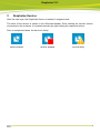
4
First Start-up of the Software
LEN and TIF files are prepared for exposure on a CDI using the "Merger". It positions the
images on the printing plate, and can also rotate, mirror, crop and invert the images as required.
The "Viewer" is used to display and measure the LEN/TIF files. The angle and the rasterization
can also be measured.
The "Exposer" controls the CDI with the jobs prepared by the "Merger".
All important settings are copied over during an update. If the software is being installed for the
first time, the network settings must be set.
4.1 Entering the License Key
During initial installation or when updating from an older version, the license key must be
entered to start the "Merger":
The ESKO-Service provides a serial number for this "ProductID" which needs to be entered in
the "Serial Number" field and confirmed by ENTER. The license can be subsequently changed
with the "New License" program in the Windows Start Menu under "Esko - Digital Flexo Suite System".
4.2 Setting the Language
In the "Merger", the language can be changed under "Edit – Change language":
10
Grapholas 12.1
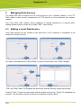
5
Managing Data Sources
The image data can be loaded from the local hard drive, over a network release, or via FTP.
With regard to data security, transmission via FTP protocol is to be preferred over network
release.
The "User Data" path entered during installation is already released as a network drive.
Additional data sources can be set up under "Edit – Data Source".
5.1 Adding a Local Data Source
Local data sources can be located on the hard drive of the computer or accessible in the
network via "share" function.
The name of the data source "Drive Name" (3) will be shown later in the "Load" dialogue.
"Disk" and "Sub Folder" (6) designate the drive letter and the directory containing the data.
Clicking "Test" (7) opens a new window with the data source set up. "Finish" (9) completes the
process. You can always switch to the previous page by pressing "Back".
11
Grapholas 12.1
5.2 Adding an FTP Data Source
The FTP server of the data source requires a virtual directory. For a detailed installation
manual, refer to "Digital Flexo Suite 101 Installation".
The name of the data source "Drive Name" (3) will be shown later in the "Load" dialogue.
Enter the IP address or the network name in the "Host" field (6). Enter the "User Name" (7) and
the "Password" (7) as shown in the illustration if the FTP server was installed as specified.
"Disk" and "Sub Folder" (9) designate the virtual drive and the directory containing the data.
Should no virtual directory be available, leave the "Disk" field empty.
Clicking "Test" opens a new window with the data source set up. "Finish" completes the
process. You can always switch to the previous page by pressing "Back".
12
Grapholas 12.1
5.3 Changing an Entry
The settings of the data source can be subsequently changed.
After selecting the "Drive" (3), you can change the following settings.
5.4 Deleting an Entry
After selecting the "Drive" (3), you can remove it by pressing "Remove" (4).
5.5 Saving Settings
Exiting via "Quit" opens a new window prompting whether you want to overwrite the current
settings.
Pressing "OK" saves the current settings.
13
Grapholas 12.1
6
Working with Interchangeable Lenses (Optional)
Optionally, the CDI can be equipped with interchangeable lenses. This allows you to use two
different resolutions like "Standard" and "HighRes" or "HighRes" and "Secuflex".
Here, the software makes use of two profiles which must be selected when starting the service.
The optics automatically configures the according lens system. An Esko technician sets up the
system.
IMPORTANT: The jobs are saved separately for each profile. In case you want to send
jobs from a PlatePrep, you need to select the correct profile first.
6.1 Starting the Service
As before, you must start the service manually after switching on the CDI. The service menu
provides an overview of the existing profiles:
The service is started by left-clicking on the desired profile.
The checkmark in front of the profile indicates that this profile is active even though the
service has not been started yet.
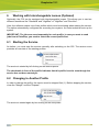
6.2 Changing to Another Profile
In order to change the profile, the service must be stopped first (1). Before stopping the service,
close the "Merger" and the "Exposer".
The service is started again by left-clicking on the new profile.
14
Grapholas 12.1
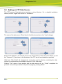
7
Adjusting the "Merger" User Interface
The user interface and some of the functions of the "Merger" can be customised and protected
with a password ("Edit – Configuration"):
7.1 Password-Protecting Functions
Left-clicking on "Enter Password" opens a new window in which the password is entered twice
and confirmed with "Close":
15
Grapholas 12.1
7.2 Changing the Password
Left-clicking on "Change Password" opens a new window in which the current password is
entered once and the new password is entered twice. "Close" confirms the input:
7.3 Entering a Password to Change Settings
Left-clicking on "Unlock" opens a new window in which the current password is entered. "Close"
confirms the input and enables the input mask:
16
Grapholas 12.1
8
Merger
The "Merger" is used to load the image data from the local hard drive or from the network and to
send it to the preselected CDI.
In addition, simple tools such as "mirror", "crop" and "rotate" are available.
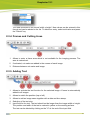
8.1 Quick Start
1
Start the "Merger" and load the required images. They are displayed in the image
gallery (on the right).
3
Position the images on the working surface. Right-click on the images or the
working surface to display additional information.
4
Select the required plate. Right-click on the plate to display additional information.
5
Send the job.
17
Grapholas 12.1
8.2 The User Interface
The "Merger" can be divided into four areas:
Area 1:
menu bar / toolbar with icons for the most important options
Area 2:
working surface on which the images are positioned
Area 3:
display of loaded image data
Area 4:
status bar - display of the most important settings
18
Grapholas 12.1
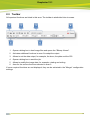
8.3 Toolbar
All important functions are listed in this area. The toolbar is subdivided into six areas:
1
Opens a dialog box to load image files and opens the "Bitmap Viewer".
2
Activates additional functions in area 6 to adapt the output.
3
Allows to set the data output, for example, the drum, the plate and the CDI.
4
Opens a dialog box to send the job.
5
Allows to modify the image data, for example, rotating and cutting.
6
Area for the various functions selected in area 2.
If some required functions are not displayed, they can be activated in the "Merger" configuration
settings.
19
Grapholas 12.1
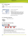
8.3.1 Loading Images
Ctrl + E
calls up a file dialog box in which the LEN or TIF files can be selected.
1 Selection of network shares.
2 Display of directories.
3 Display of files. By pressing the "Control" or the
CAPS button together with the left mouse button,
several files can be marked simultaneously; they
can then be loaded by pressing "OK". Single files
can directly be loaded by double-clicking them.
4 Multiple loading of the files.
8.3.2 Displaying Image Data
Opens the "Bitmap Viewer".
8.3.3 Plate Size and Partial Plate
1
Display of the drum circumference – This value can be changed for sleeves.
2
Switchover to partial plate – In this mode, the vacuum on the CDI is not analysed
and is reduced to a lower, safer speed.
3
Allows to set the plate width in partial plate mode.
4
Allows to set the plate height in partial plate mode.
5
Display of the list of partial plates – Plate width and plate height are selected from a
list:
20
Grapholas 12.1
The data is entered in the format 'width x height'. New values can be entered in this
format and can be added to the list. To delete an entry, select said value and press
the "Delete" key.
8.3.4 Frames and Cutting Lines
1
Allows to enter a frame area which is not available for the imaging process. The
area is marked red.
2
If activated, cut marks are added in the corners of each image.
3
Distance between cut marks and image.
8.3.5 Adding Text
1
Allows to activate the text function for the selected image. A frame is automatically
added to all images.
2
Allows to switch the position (top or left).
3
Allows to add an image name together with a date and time stamp.
4
Selection of the text size.
5
Input field for the text. The text should not be longer than the image width or height.
The position and width of the text is marked in yellow on the working surface.
The text can be deleted by clicking on the "X" at the end of the input field.
21
Grapholas 12.1
8.3.6 Information on Grids and Image Position
1
Allows to enter the raster count and the angle if they have not yet been included in
the image. Images without this information are marked in red on the working
surface.
2
Allows to mark an image as a test wedge. For this image, the output optimisation
function is deactivated to increase productivity. If these two fields are highlighted in
grey, then they are irrelevant for the selected CDI.
3
Allows to display and change the current image position.
4
Confirmation of the changed image position. The image is not positioned until the
changed image position is confirmed.
5
Allows to activate the overlaying option. The images can be positioned on top of
each other. Using the arrows, the selected image can be positioned above or below
another image.
6
Allows to display and change the image to make further changes.
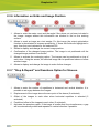
8.3.7 "Step & Repeat" and Seamless Option for Sleeves
1
Allows to enter the number of repetitions in horizontal and vertical direction. It is
possible to set a gap between the images.
2
Displacement of the image above the zero point of the sleeve (5 activated).
3
Offset of the images to each other when horizontal repetition is selected (5
activated).
4
Predefined offset of the images to each other (5 activated).
5
Activates the seamless option. If the image is smaller than the circumference, a gap
will be automatically added and repeated in vertical direction if possible.
22
Grapholas 12.1
8.3.8 Mirroring and Inverting
If this icon is not displayed, it can be displayed by selecting "Image Manipulation" under
"Options - Configuration".
Allows to mirror (horizontally or vertically) and invert the selected image. "ymir", "xmir" or "inv" is
added to the new files.
8.3.9 Output Options
1
Selection of the drum on the CDI. This option is only shown if more than one drum
or the drum and the sleeve have been set up on the CDI.
2
Selection of the plate. To ensure an optimum imaging result, the right plate needs to
be selected. Additional information such as "UV Inline" and "Full HD Flexo" is stored
on the plate.
Normal plates are marked with a circle and Inline UV plates are marked with a
square.
Right-clicking the plate entry displays information on the plate properties.
Only the plate types which fit the selected drum are displayed.
For more information, refer to chapter "Managing the Plate List".
3
Selection of the required Kongsberg settings. If activated, a yellow bar is visible on
the left or on the bottom in the "Merger".
The cutting file for the Kongsberg is stored in the directory which was selected for
this setting.
23
Grapholas 12.1
For more information, refer to chapter "Kongsberg Output (XL CUT)".
4
Selection of the output device. CDIs and TIF output devices are listed separately.
8.3.10
Generating a Job
Ctrl + E
opens a dialog window in which the job name can be entered.
Pressing "OK" sends the job.
8.3.11
Cropping and Rotating Images
1 Automatic cropping of the selected images. Unused frame
areas are removed.
Right-click the icon to undo the changes.
The distance to the "Bleed" pixels can be set in the
"Merger" properties. If the image contains "Staggered Cut"
information, the image is cut on the cutting line.
2 Opens a new window in which the image can be cut. For
more information, refer to chapter "Manual Cropping".
3 Rotates the selected images by 90°. The rotated files are
generated when sending the data to the output device.
Depending on the resolution, this may take some time.
8.3.12
Automatic Positioning of the Images
The images loaded in the "Merger" can be positioned automatically.
Press Ctrl + a to automatically reposition all images. Already positioned images are removed
from the working surface.
Press Ctrl + h to automatically position all images which have not yet been positioned. Already
positioned images are not removed in this case.
As soon as more than one image has been marked (Ctrl + left mouse button), only these
images will be used for automatic positioning.
24
Grapholas 12.1
Images with different resolutions cannot be sent to the CDI on a plate. If more than one
resolution is available for automatic positioning, a selection is displayed.
Only the images with the selected resolution are positioned.
The way how the images are positioned can be determined in the basic settings of the
"Merger". If the images must be cut manually afterwards, "Cut-Optimised Positioning" can
be used.
8.3.13
Manual Cropping
opens a new window in which the image can be cropped:
Starting from the frame area, a lasso can be pulled open by pressing and holding down
the left mouse button and pulling the mouse across the working surface; or the exact lasso size
can be entered in the four input fields on the right-hand side (1).
The distance between two positions in the image can be measured by pressing and
holding the left mouse button down.
25
Grapholas 12.1
Individual sections of the image can be enlarged with a square magnifier by pressing and
holding down the left mouse button and pulling the mouse across the section of interest. Using
the arrow keys on the keyboard, the image section can be moved in the desired direction.
displays the entire image.
performs the automatic cropping.
sets back all cutting edges.
saves the current image section as a new LEN file.
Manual cropping is not available for LEN files of the "PlatePatcher" and the "Staggered
Cut".
8.4 Menu Bar
Only the additional functions which are not listed in the toolbar are described. The menu bar is
located above the toolbar.
8.4.1 Unloading Images
"File - Unload Image" (Ctrl + u) removes the selected image from the "Merger". The file is not
deleted from the hard drive.
8.4.2 Unloading Positioned Images
"File - Remove All Positioned Images" (Ctrl + d) removes all images from the "Merger"
which are positioned on the working surface. The files are not deleted from the hard drive. This
is useful when the job was sent and several images are still in the queue.
8.4.3 Selecting the Working Directory
"File - Select Working Folder" (Ctrl + w) changes the working directory in which all images
are copied or moved during the loading process. This option is not available if images are
loaded.
8.4.4 Saving the Image Arrangement
"File - Save Plate" (Ctrl + s) saves the compiled images and the exposure parameters as
plate. When the compiled images are sent to the CDI, the plate is automatically saved under the
entered name.
"File - Save Plate as" saves the compilation under another name.
26
Grapholas 12.1
8.4.5 Loading the Image Arrangement
"File - Load Plate" (Ctrl + L) loads a previously saved or sent compilation with all parameters.
All currently loaded images are removed.
8.4.6 Deleting the Image Arrangement
"File - New Plate" (Ctrl + n) removes all images from the "Merger" and resets the parameters.
8.4.7 Automatic Positioning of the Images
"Position - Auto Arrange Images" (Ctrl + a) automatically positions as many loaded images
as possible on the working surface. Beforehand, images which were already positioned on the
working surface are removed. The type of positioning can be selected in the "Merger"
properties.
8.4.8 Automatic Positioning of New Images
"Position - Auto Arrange New Images" (Ctrl + h) automatically adds the loaded images to the
compilation on the working surface. Already positioned images are not removed.
8.4.9 Removing Images from the Working Surface
"Position - Unplace all" (Ctrl + u) removes all images from the working surface. The images
are not unloaded.
8.4.10
Displaying File Names
"Windows - Display Names" shows the file names in the images positioned on the working
surface.
8.5 Working Surface and Status Bar
The working surface shows the available area on the plate. It is not necessary to enter the
upper and lower borders as the entire working area is shown.
The loaded images are pulled from the right queue on the working surface by holding down the
left mouse button.
27
Grapholas 12.1
In addition, guides can be pulled from the grey frame area by holding down the left mouse
button. The images cannot be positioned in the red area. The guide can be removed again by
right-clicking on the grey frame area.
Right-clicking the image file displays information on the image.
The status bar shows the current settings and the number of loaded images.
8.6 Displaying Plate Use
Right-clicking on the working surface displays information on the plate size and the use of the
plate.
The "Partial Plate" line shows the values for the marked area. The "Full Plate" line refers to the
entire work area.
8.7 Managing Plate List
"Edit – Edit Plate List" opens a new window where you can delete, change and create new
plates.
"Cancel" aborts the process – no data is changed. By pressing "Quit", the window is closed.
"Next" shows the next window.
28
Grapholas 12.1
8.7.1 Creating a New Plate
First select the desired medium "Plate Type" (1), then check "New" (2) and press "Next" (3) to
go to the next menu:
"Plate" – Flexo plates
"Sleeve" – print sleeve of DuPont and Flint
"Plate on Sleeve" – Flexo plates mounted on a print sleeve
"Steel Base" – metal backing plate for magnetic drum
"Film" – film
If Grapholas 10.1 or higher is installed on the CDI, a plate database is shown. When the desired
plate manufacturer "Brand" (4) or the plate type "Plate" (5) are not available, the option
"other" can be selected:
"Name" (7) determines the display name in the plate list and "Thickness" (7) the plate
thickness. For sleeves, the circumference is entered in the "Circumference" field (7):
29
Grapholas 12.1
Additionally, the output in the "Distortion" field (7) can be distorted in circumference direction.
The input is made as a percentage. If you enter "5.0", the output is enlarged by 5 percent in
circumference direction. Entering "-5.0" would downsize the output accordingly.
Under "Manual" (9), enter the values for "Speed" (10) and "Laser Power" (10). The setting
"Energy" (9) sets the "Laser Energy" (10), and speed and performance are selected
automatically according to the resolution:
With Inline UV, enter for the front exposure the values "UV Main Exposure" (13) and "UV Main
Energy" (13) and with automatons, enter for the back exposure the values "UV Back
Exposure" (14) and "UV Back Energy" (14). You can disable the UV exposure by checking
"No UV" (12).
UV2 exposure parameters are specified in section "Full HD UV Parameters" (14) when the
CDI has been prepared for Full-HD Flexo.
"Finish" (16) saves the plate.
30
Grapholas 12.1
8.7.2 Changing the Plate
First select the desired medium "Plate Type" (1), then check "Edit" (2) and press "Next" (3) to
go to the next menu:
After setting the desired "Plate" (4), you can change all parameters except for the plate name.
"Next" opens the next menu.
8.7.3 Deleting the Plate
First select the desired medium "Plate Type" (1), then check "Edit" (2) and press "Next" (3) to
go to the next menu:
The desired plate "Plate" (4) is set and removed by pressing "Remove" (5).
31
Grapholas 12.1
8.8 Exposing Plate Borders
The "Expose frames" option can be activated in the basic settings of the "Merger" under "Edit –
Preferences…", giving the plate more stability in the washer.
The left and the right border can be set in the "Drum Window" and is now shown in white. When
the TIF output is negative, the border is displayed in black.
8.9 Templates
If these functions are not displayed, they can be activated in the basic settings.
The positions, image sizes, image resolution and plate parameters are stored in the template in
order to position images quickly at a later time. This working mode is interesting for register
pinwheels such as, e. g., for Letterpress.
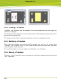
8.9.1 Creating a Template
To create a template, you first position the required images onto the working surface and then
select the plate type. This compilation is then saved by pressing "Template - Save Template".
32
Grapholas 12.1
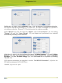
8.9.2 Loading a Template
"Template - Use Template" loads the template. This is only possible when no other images are
loaded in the "Merger".
The stored positions and sizes are shown as yellow fields. After loading the images, they can be
positioned in the yellow fields.
The images must be within a certain size tolerance in order to be assigned to a field.
8.9.3 Modifying a Template
After loading the template and positioning all the images, the mask can be opened using
"Template - Edit Template". Now you can change all parameters as required and save them
using "Template - Save Template".
The modified template can now be loaded using "Template - Use Template".
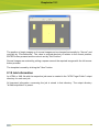
8.9.4 Moving a Template
"Template - Correct Template" opens a new program in which the template can be loaded using
"File – Load Plate".
33
Grapholas 12.1
The position of single images or of several images can be changed horizontally by "Across" and
vertically by "Circumference". The value is entered absolute or relative to the current position,
ENTER is then pressed and the value is set by "Set Position".
Several images are marked by pulling a square around the required images with the left mouse
button pressed.
The template is saved by clicking the "Save" button.
8.10 Job Information
An HTML or XML file with the respective job name is created in the "HTM Target Folder" output
directory for each sent job.
All important information concerning the job is stored in that directory. The output directory
"d:\files\output\html" is preset.
34
Grapholas 12.1
8.11 Loading Images via "Drag & Drop"
Image files (LEN and TIF) can directly be dragged into the right image bar of the "Merger" from
the Windows Explorer. First, the data is copied into the working directory, then it is loaded. If the
"Ctrl" key is pressed at the same time, the files are always copied.
8.12 "Unique ID"
All LEN and/or TIF files from an AE12 system contain a unique code which can be read by the
"Merger".
As soon as the "Unique ID" option is activated under "Options – Configuration", this code is
added to all images.
35
Grapholas 12.1
8.13 Basic Merger Settings
The basic settings of the "Merger" can be changed via the menu item "Options –
Preferences…":
"Units" switches between "mm" and "inch".
"Digits" and "Post colon" set the amount of numbers and/or decimal points.
"Check Images before start" checks the images of all outgoing jobs.
"File copy method" sets the behavior while loading images. With the setting "Copy", the files are
always copied; if "Move" is selected, they are deleted from the source directory.
"Bleed" sets the border during automatic cropping.
"Expose left frame": When activated, the left border is exposed to provide more stability for the
washer.
"Show Ruler" activates or deactivates the ruler.
When restarting the "Merger", "Autoload Job" actuates automatic loading of the last job.
"Archiving Interval:" determines the number of days after which the HTML overview files and the
files of the "Mergelog" directory are archived in a ZIP file.
"JDF Server": Enter IP number or computer name of JDF server.
"Autoplace mode:" sets the method (mode) of how the images are automatically arranged on
the working surface. The methods to be selected are fast, space-optimised and cut-optimised
positioning.
In most cases, the fast positioning method is sufficient. The space-optimised positioning method
tries to position the images until the maximum time "Timeout" is reached. The cut-optimised
positioning method positions the images so that the plates can be better cut manually
afterwards.
36
Grapholas 12.1
"Auto Rotate" activates rotating during automatic positioning to save more space.
In the "Folder" window, the preset output directories can be changed.
The job information is saved in the "HTM Target Folder" directory.
Under "Plugins", the minimum size for "Microcross" and "Centerline" images can be entered.
The images are automatically enlarged to this size.
The "Merger" must be restarted after any change.
37
Grapholas 12.1
9
Exposer
The "Exposer" starts the jobs sent from the "Merger". In addition, a focus search or, for sleeves,
a zero point search can be performed here.
The "Exposer" is divided into four areas:
Area 1:
Status Displays and Controls
Area 2:
Vacuum Display and Position Control
Area 3:
Job List and Status Display
38
Grapholas 12.1
Area 4:
Machine Controls
9.1 Status Displays and Controls
The CDI status is displayed with icons. Depending on the version, the status of the UV
exposure and the automaton can be displayed here.
If several drums are registered, the currently used drum can be selected in the "Drum" field.
When using "Advance Cantilever", an automatic search for the clamping bar is carried out as
soon as "Drum Sleeve" is selected.
9.2 Vacuum Display and Position Control
"Engraving Axis" displays the current position of the laser. The desired start position for the
imaging process is entered in the "Position" field and run by pressing [ENTER]. "Home" moves
the laser back to 1 mm.
"Pressure" displays the vacuum. For full plates, a vacuum of over 900 mbar is required. The
engraving process cannot be started unless the required value has been reached. For partial
plates, the vacuum is not analysed since the speed was reduced to a safe value.
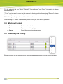
9.3 Job List
The "Job" name, the "Plate" type and the job "Status" are displayed for each job:
Completed job.
Imaging has started.
Imaging has stopped.
The job contains parameters for UV front exposure.
The job contains parameters for UV back exposure.
Data is loaded.
Error when transferring data.
Job status is shown in the AE10.1 Pilot.
Repetition after JDF exposure is not possible.
39
Grapholas 12.1
For the selected job, the "Width", "Height", "Circumference" and "Drum" information is shown
below the job list.
"To top" can be used to move the job selected to the top position for imaging. "Remove" deletes
the selected job.
Right-clicking on the job shows additional information.
Right-clicking on "Status" changes the position of the job, even during operation.
9.4 Machine Controls
Start
Start the selected job.
Pause
Stop the current imaging process.
Cancel
Cancel the current imaging process.
9.5 Changing the Priority
By right-clicking into the status column, you can change the position of a job during operation.
40
Grapholas 12.1
9.6 Job Information
opens a new window with the job overview.
When the mouse is above an image in the upper overview, the respective list entry is
highlighted.
The list contains the positions, dimensions and names of the job images.
In the lower status bar, the XL CUT name and the template name are displayed. Furthermore,
the overview can be printed by clicking on the printer icon.
This information is only available if the job on the CDI was sent or the PlatePrep corresponds at
least with the "Version 10 Patch 2".
41
Grapholas 12.1
9.7 Starting a job
The desired job is selected from the list and run with the "Start" button. The job's remaining time
is displayed on the bottom of the status bar.
"Pause" stops the engraving. "Start" can be used to resume it, but may cause a seam in the
imaging. "Cancel" cancels the job.
When the exposure is completed, a dialog window is displayed where the job can be deleted or
put back into the queue.
9.8 Focus Search
The focus search is used to set the distance of the laser to the plate in place. The focus setting
is very important for achieving the optimum imaging quality:
The plate in place has to be selected under "Plate Types". The start of the focus search is set
using "Start (Around drum)".
For partial plate mode, the "Partial Plate" option has to be activated.
The focus search is lined up as new job in the "Exposer" by clicking on "OK" and started as
normal job in the "Exposer".
The deactivated input fields can be enabled using the "Advanced" button.
42
Grapholas 12.1
When the focus search is ended, the "FocusDialog" dialog box is displayed in which the position
of the thinnest line in the focus search has to be entered in the "Best Track" field. "OK" changes
the focus setting in line with the input.
9.9 Zero Point Search for "Sleeves"
To determine the zero point on a sleeve, the job to be exposed is lined up in the "Exposer" first
and then the zero point search is started via "Options". The parameters are displayed in a new
window; an "Offset" can be entered in advance:
By pressing "OK", the job "Zero_esko_special" is lined up in the "Exposer". A ruler will be
engraved on the sleeve. The zero point on the ruler corresponds to the zero point of the sleeve.
9.10 Determining the Full HD UV / Pixel+ Parameters ("Steptest")
For each plate type, the Full HD UV / Pixel+ parameters must be determined.
The "Step Test" uses the first job in the "Exposer" to automatically develop a test series with 16
different parameters.
To do so, the top job must have been created using the Full HD UV or Pixel+ option and must
still fit on the plate after the broadening.
After printing this plate, the determined parameter is loaded into the system by ESKO service
technicians.
9.11 UV Exposure "UV Inline" (Option)
"UV Inline" exposes the upper side of the plates. This function can be activated or deactivated
via "UV Unit". When the CDI is restarted, the UV exposure is automatically activated unless the
external cooler is switched off.
The service technician adapts the UV parameters for the desired plate types. If no UV
parameters are adapted for some plates, they will be started without UV exposure. If the UV unit
is deactivated, a warning is displayed when starting the exposure if UV parameters are
available for this plate type.
43
Grapholas 12.1
The status of the UV unit is displayed with the following icons:
UV unit activated
UV exposure activated
9.12 Control of the Automaton
9.12.1
UV Back Exposure
The UV back exposure is available as an option for the automaton. This function can be
activated or deactivated via "UV Unit". When the CDI is restarted, the UV back exposure is
automatically activated.
The service technician adapts the UV parameters for the desired plate types. If no UV
parameters are adapted for some plates, they will be started without UV back exposure.
The status of the UV back exposure unit is displayed with the following icons:
UV back exposure unit activated
UV back exposure activated
9.12.2
Control and Status Displays
Under "APL", the automatic function of the automaton can be activated or deactivated. The
status of the automaton is displayed with the following icons:
No plate loaded.
The plate is located on the drum.
The plate is located in the tray.
The plates are located on the drum and in the tray.
44
Grapholas 12.1
9.13 Control of the Tailstock – CDI Cantilever
For the Cantilever, the tailstock can only be moved when the cover is closed. There must
not be any objects in the tailstock's area of movement.
In the "Tailstock" menu, "Lock" can be used to close the tailstock and "Unlock" can be used to
open the tailstock.
9.14 Interlocks and Errors
An active interlock prevents imaging from starting and is symbolised in the "Exposer" by a
crossed-out drum:
Left-clicking this icon updates the interlock display.
Active machine errors and interlocks are displayed in the section "Active Interlocks" with a red
point.
UV system errors are displayed in the section "UV Unit" and can only be reset in this section by
selecting the "UV Reset" button.
"Limit Switches" shows the status of the different axes and is only used as information.
45
Grapholas 12.1
If the vacuum is too weak, this is also displayed in the status display in the form of a red plate
under the roller.
The status is reset by clicking on the drum.
46
Grapholas 12.1
10
Support Europe
To contact ESKO, please visit www.esko.com.
47