1
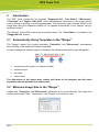
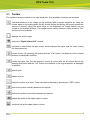
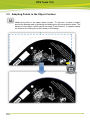
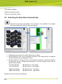
DFS TOOLS 12.0 USER MANUAL 28.03.2013 DFS Tools 12.0 © Copyright 2013 Esko-Graphics Imaging GmbH, 25524 Itzehoe, Germany All rights reserved. This document and the information and instructions contained therein is the property of Esko-Graphics. These documents contain the product descriptions according to their current state at the time of publication, subject to confirmation. No guarantees are granted or expanded upon by this document. Furthermore, Esko-Graphics will not guarantee for illustrations relating to the usage of the products or for results from using the software or the use of the information contained herein. EskoGraphics is not responsible for direct or indirect damages or damages caused as logical consequence or latent damages resulting from the use of the software or from the impossibility of using the software or of the information contained herein. The technical data contained herein and the content of this manual is subject to change without prior notification. Revisions may be issued from time to time that inform of such changes and/or supplements. No part of this document may be reproduced, transferred, electronically stored or published, irrespective of the reasons without written permission and irrespective of the method or means used, i. e., electronic, mechanical, by printing, microfiche, etc. These documents replace all previous versions. Grapholas® is a registered trademark of Esko-Graphics Imaging GmbH. Cyrel®, Cyrel® Digital Imaging System and Cyrel® Digital Imager (CDI) are registered trademarks of DuPont. Microsoft and the Microsoft Logo are registered trademarks of Microsoft Corporation in the USA and other countries. The software from Esko-Graphics may contain the "RSA Data Security, Inc. MD5 Message-Digest Algorithm". JDF and the JDF Logo are trademarks of the CIP4-Organisation. Copyright 2001 The International Cooperation for the Integration of Processes in Prepress, Press and Postpress (CIP4). All rights reserved. Java and all Java-based trademarks and logos are trademarks or registered trademarks of Sun Microsystems in the U.S. and/or other countries. Some parts of this software use technologies of JGoodies, Barbecue (Copyright 2003, International Barcode Consortium), and Jakarta (licensed by Apache: www.apache.org/licenses/LICENSE-2.0.txt). All other product names are trademarks or registered trademarks of their respective owners. 2 DFS Tools 12.0 TABLE OF CONTENTS 1 INSTALLATION ............................................................................................................................................. 5 2 INTRODUCTION ........................................................................................................................................... 6 2.1 AUTOMATICALLY USING TEMPLATES IN THE "MERGER" ............................................................................................ 6 2.2 MINIMUM IMAGE SIZE IN THE "MERGER" .............................................................................................................. 6 3 "STAGGERED CUT" ...................................................................................................................................... 7 3.1 TOOLBAR ......................................................................................................................................................... 8 3.2 CREATING A NEW CUTTING LINE ........................................................................................................................ 10 3.3 ADAPTING POINTS TO THE OBJECT CONTOUR ....................................................................................................... 11 3.4 CREATING A LINE AT THE OBJECT CONTOUR.......................................................................................................... 12 3.5 CUTTING MARGINS.......................................................................................................................................... 13 3.6 DETECTING THE BEAR BARS AUTOMATICALLY ....................................................................................................... 14 3.7 CREATING VERTICAL AND HORIZONTAL LINES........................................................................................................ 15 3.8 CREATING LINES AUTOMATICALLY ...................................................................................................................... 16 3.9 CENTRING POINTS ........................................................................................................................................... 18 3.10 APPLYING THE CUTTING LINE TO THE ENTIRE JOB ................................................................................................... 19 3.11 EXPORT FINISHED FILES .................................................................................................................................... 20 4 "LINE EDITOR" ........................................................................................................................................... 21 4.1 USING MASKS ................................................................................................................................................ 22 4.1.1 4.1.2 Applying a Mask to the Entire Job: .................................................................................................. 22 Applying a Mask to One Ink Only: ................................................................................................... 22 4.2 CONTOUR RECOGNITION .................................................................................................................................. 23 4.3 CREATING RECTANGLES .................................................................................................................................... 24 4.4 CREATING LINES .............................................................................................................................................. 25 4.4.1 4.4.2 Moving Lines ................................................................................................................................... 25 Deleting Lines .................................................................................................................................. 26 4.5 DELETING SEVERAL OBJECTS .............................................................................................................................. 26 4.6 CREATING A TEMPLATE ..................................................................................................................................... 26 4.7 LOADING A TEMPLATE ...................................................................................................................................... 27 4.8 LOADING AN IMAGE ......................................................................................................................................... 27 4.9 SAVING INFORMATION ..................................................................................................................................... 27 4.10 EXPORT FINISHED FILES .................................................................................................................................... 27 5 "MICROCROSS" ......................................................................................................................................... 28 5.1 AUTOMATIC CROPPING IN THE "MERGER" ........................................................................................................... 30 5.2 DETECTING MICROCROSSES ............................................................................................................................... 30 5.3 DELETING MICROCROSSES................................................................................................................................. 31 5.4 FRAME AND MICROCROSS DISTANCE................................................................................................................... 31 5.5 CREATING MICROCROSSES ON THE BACK SIDE....................................................................................................... 32 5.6 FIXED IMAGE SIZE ............................................................................................................................................ 32 3 DFS Tools 12.0 5.7 FIXED CROSS POSITIONS ................................................................................................................................... 32 5.8 MICROCROSSES WITHIN THE IMAGE .................................................................................................................... 32 5.8.1 Creating a Template ........................................................................................................................ 32 5.9 FIXED CROSS SIZE ............................................................................................................................................ 32 5.10 LOADING A JOB ............................................................................................................................................... 33 5.10.1 5.10.2 5.11 6 Saving Information .......................................................................................................................... 33 Export Finished Files ........................................................................................................................ 33 LOADING A TEMPLATE ...................................................................................................................................... 33 "CENTERLINE" ........................................................................................................................................... 34 6.1 AUTOMATIC CROPPING IN THE "MERGER" ........................................................................................................... 35 6.2 GUIDE FOR MOUNTING .................................................................................................................................... 36 6.3 SHORTENED LINES ........................................................................................................................................... 36 6.4 DETECTING MARKS .......................................................................................................................................... 37 6.5 DELETING MARKS............................................................................................................................................ 37 6.6 FRAME .......................................................................................................................................................... 38 6.7 CREATING A TEMPLATE ..................................................................................................................................... 38 6.8 LOADING A TEMPLATE ...................................................................................................................................... 38 6.9 LOADING AN IMAGE ......................................................................................................................................... 38 6.10 SAVING INFORMATION ..................................................................................................................................... 39 6.11 SAVING INFORMATION IN ALL COLOURS .............................................................................................................. 39 6.12 EXPORT FINISHED FILES .................................................................................................................................... 39 7 "DIGITAL VIDEO DRILL" ............................................................................................................................. 40 7.1 DETECTING MARKS .......................................................................................................................................... 41 7.2 MANUALLY SETTING DRILL HOLES ...................................................................................................................... 42 7.3 MOVING DRILL HOLES...................................................................................................................................... 42 7.4 DELETING DRILL HOLES .................................................................................................................................... 42 7.5 CREATING A TEMPLATE ..................................................................................................................................... 42 7.6 LOADING A TEMPLATE ...................................................................................................................................... 42 7.7 LOADING AN IMAGE ......................................................................................................................................... 42 7.8 SAVING INFORMATION ..................................................................................................................................... 43 7.9 SAVING INFORMATION IN ALL COLOURS .............................................................................................................. 43 7.10 EXPORT FINISHED FILES .................................................................................................................................... 43 4 DFS Tools 12.0 1 Installation The installation must be carried out as administrator on the local computer (not domain). User rights are usually restricted when logged on to a domain. After inserting the CD, the start screen is automatically displayed. If the start screen is not displayed, then start the "setup.exe" file in the root directory of the CD. The installation starts with a selection of the installation directory and the dialog language. 5 DFS Tools 12.0 2 Introduction The "DFS Tools" contain the five modules "Staggered Cut", "Line Editor", "Microcross", "Centerline" and "Digital Video Drill" which add additional information to the image files for cutting, drilling or drawing on the Kongsberg table. This information can be saved directly in the image data using the respective module or it is applied automatically in the "Merger" using a template function. The "Merger" of the DFS requires an according license. The "Line Editor" is included in the "Staggered Cut" license. 2.1 Automatically Using Templates in the "Merger" The "Merger" applies the module templates "Centerline" and "Microcross" automatically when loading, if the respective license is available. In order to assign the loaded image to a template, the following name policy must be applied: 1. consecutive job number or customer number 2. template name 3. job name 4. colour name The dimensions of the image must comply with those of the template, and the name segments must be divided by an underscore. 2.2 Minimum Image Size in the "Merger" Images with "Centerline" and "Microcross" information are cut automatically. The image size can be limited under "Edit – Preferences", tab "Plugins" to a minimum value: 6 DFS Tools 12.0 3 "Staggered Cut" The "Staggered Cut" module used to edit image files can be found in the Windows Start Menu under "ESKO – DFS Tools" or "ESKO – Digital Flexo Suite – DFS Tools". Cutting lines created by Plato cannot be edited with the "Staggered Cut" module. LEN or TIF files are loaded using "File – Load Image". TIF files are converted automatically to LEN files so that additional information can be saved. 7 DFS Tools 12.0 3.1 Toolbar The toolbar is always located on the right-hand side. Only available functions are activated. Individual sections of the image can be enlarged with a square magnifier by using the mouse wheel or by holding down the left mouse button and pulling the mouse across the section of interest. Using the arrow keys on the keyboard, the image section can be moved in the desired direction. The image section can be zoomed out by pressing "Ctrl" and the left mouse button. displays the entire image. opens the "Digital Video Drill" module. activates or deactivates the split screen which displays the upper and the lower cutting line simultaneously. moves a point. By pressing this button and the "Ctrl" button, the distance to the original position is displayed in addition. moves the upper line. For this purpose, a point is moved with the left mouse button. By pressing this button and the "Ctrl" button, the distance to the original position is displayed in addition. adds a point. deletes a point. marks the points in an area. These can then be deleted by pressing the "DEL" button. centres the points vertically between two objects. centres the points horizontally between two objects. adapts the points to the upper object contour. creates a line at the upper object contour. 8 DFS Tools 12.0 The distance between two positions in the image can be measured by pressing and holding the left mouse button down. corrects excessively acute angles so that the plate will not crack in these areas. cuts the margins. This function is only available if the entire image is displayed. changes the margins. This function is only available if margins were automatically created beforehand. creates an additional vertical line at the desired position by clicking the left mouse button. creates an additional horizontal line at the desired position by clicking the left mouse button. detects the desired position for the vertical cutting line automatically. The section containing the object must be enlarged beforehand. detects the bear bars automatically. This function is only available if the section with the bear bars was enlarged. loads a saved cut. saves the current cut. indicates that a new cutting line must be created. deletes the cutting line. "Design Height" sets the distance between the upper and the lower cutting line. "Bar Height" sets the height of the bear bars. This function is only available if bear bars were detected. "Shrink" reduces the lower line for a gapless mounting of the plates. "Sample Step" and "Line Distance" are available if the adaptation to the object contour is selected. With these functions, the distance between the points and the distance to the object contour is set. 9 DFS Tools 12.0 "Apply To Job" applies the cut contour to the entire job. For this purpose, the cut contours must be loaded in the "Merger". "OK" applies the cut contour. "Cancel" cancels the editing process. 3.2 Creating a New Cutting Line If the file contains no cutting information, the starting point on the left side of the image must be determined by clicking the left mouse button, then the cutting lines must be added one after another with the left mouse button. Angles larger than 90° cannot be entered. The contour can only be further edited when the line was created for the entire width. The distance to the lower cutting lines can be set in the "Design Height" field. 10 DFS Tools 12.0 3.3 Adapting Points to the Object Contour adapts the points to the upper object contour. To this end, a frame is drawn around the desired area by pressing and holding the left mouse button down. The distance to the object contour can be set using "Line Distance". If negative values are entered, the cutting line will be drawn in the design. 11 DFS Tools 12.0 3.4 Creating a Line at the Object Contour creates a line at the upper object contour. To this end, a frame is drawn around the desired area by pressing and holding the left mouse button down. The distance to the object contour can be set using "Line Distance". If negative values are entered, the cutting line will be drawn in the design. 12 DFS Tools 12.0 3.5 Cutting Margins cuts the margins. This function is only available if the entire image is displayed and no bear bars have been defined yet. The red areas on the right and left of the image show the unused space. The cutting line is automatically moved to the lateral margins of the image. changes the margins. This function can also be called up by right-clicking the red area. A new window is opened in which you can enter the "Left Gap" and the "Right Gap" of the margins. 13 DFS Tools 12.0 "OK" applies changes. "Reset" removes the frame. "Cancel" cancels this change. 3.6 Detecting the Bear Bars Automatically detects the bear bars automatically. This function is only available if no margins have been defined yet and an area was enlarged. 1 Enlarge the bear bars until no other elements are visible. 2 By left-clicking on the icon for automatic detection, the image section is analysed and the detected area is displayed in green. 3 By right-clicking on the green area, a new window is opened in which the width of the bear bar can be changed asymmetrically. The last changed values will be applied automatically. "Left Outer Border" "Left Inner Border" left bear bar - left margin left bear bar - right margin "Right Inner Border" "Right Outer Border" right bear bar - left margin right bear bar - right margin Repeat this step for the second bear bar. 14 DFS Tools 12.0 Now you can enter the height of the bear bars in the "Bar Height" field. These bars will always be arranged in the centre of the cut. If the difference between "Design Height" and "Bar Height" is 20 mm, the bear bar will be 10 mm longer at the top and at the bottom than the cut. 3.7 Creating Vertical and Horizontal Lines creates an additional vertical line at the desired position by clicking the left mouse button. creates a horizontal line at the mouse position. 15 DFS Tools 12.0 Right-clicking on a line opens a new window in which the "Position" and the "Line Width" can be changed. "Remove" removes the line. When a line width of "0" is entered, only one line is created. When "2" or more is entered, two lines will be inserted having this distance. 3.8 Creating Lines Automatically detects the desired position for the vertical cutting line automatically. The section containing the object must be enlarged beforehand. 16 DFS Tools 12.0 The width of the first detected object is automatically used as line width for all vertical cutting lines. If not requested, the line width can be changed by right-clicking the vertical line. 17 DFS Tools 12.0 3.9 Centring Points centres the points horizontally between two objects. A frame can be pulled around the relevant points using the left mouse button (hold pressed and pull). If there is no graphic object on one side (top or bottom), the frame is used as border: 18 DFS Tools 12.0 centres the points vertically between two objects. 3.10 Applying the Cutting Line to the Entire Job After creating the cutting line, the "Apply To Job" button can be used to automatically transfer the cutting line to the entire job. To this end, the other separations must already have been loaded into the "Merger": 19 DFS Tools 12.0 3.11 Export Finished Files The options are set in the "File – Preferences" menu. When "Export" is activated, the job is copied or moved automatically to the output folder. Using the "Move" option for "File Copy Method", you can move the files into the output folder. 20 DFS Tools 12.0 4 "Line Editor" The "Line Editor" module used to edit image files can be found in the Windows Start Menu under "ESKO – DFS Tools" or "ESKO – Digital Flexo Suite – DFS Tools". The "Load" dialogue is shown after start-up. TIF files are converted automatically to LEN files so that additional information can be saved. Individual sections of the image can be enlarged with a square magnifier by using the mouse wheel or by holding down the left mouse button and pulling the mouse across the section of interest. Using the arrow keys on the keyboard or the right mouse button, the image section can be moved in the desired direction. The image section can be zoomed out by pressing "Ctrl" and the left mouse button. displays the entire image. activates the setting of lines using the left mouse button. activates the contour recognition feature using the left mouse button. automatically creates a rectangle around the objects in the visible area. 21 DFS Tools 12.0 marks a line so it can be deleted. marks a line so it can be moved. marks several objects so they can be deleted. loads a stored template. saves the information in a template. The distance between two positions in the image can be measured by pressing and holding the left mouse button down. deletes the information. 4.1 Using Masks The software does not recognise halftone screen areas as a contour. To write the corresponding cut contour into a file with halftone screen areas, a file with a solid area is required for each job or ink. The file with a solid area is loaded and edited using the "Line Editor". When pressing "OK", the information is additionally written into the desired file with the halftone screen areas provided that "FREECUT" is used in the file name as follows. 4.1.1 Applying a Mask to the Entire Job: Mask: jobname_FREECUT.len Ink 1: jobname_ink1.len Ink 2: jobname_ink2.len 4.1.2 Applying a Mask to One Ink Only: Mask 1: jobname_ink1_FREECUT.len Ink 1: jobname_ink1.len Mask 2: jobname_ink2_FREECUT.len Ink 2: jobname_ink2.len 22 DFS Tools 12.0 4.2 Contour Recognition activates the contour recognition feature. Left-clicking selects the desired contour. The first black-to-white change to the left of the selected mouse position is used as the starting point for the contour. The distance to the selected contour can be set in the "Line Distance" field. To maintain this distance, the corners receive a round contour: 23 DFS Tools 12.0 4.3 Creating Rectangles Automatically creates a rectangle around the objects in the visible area when left-clicking this option: The distance to the selected contour can be set in the "Line Distance" field. 24 DFS Tools 12.0 4.4 Creating Lines creates vertical and horizontal lines across the entire image height or image width using the left mouse button. 4.4.1 Moving Lines marks a line so it can be moved. The line can be moved manually using the left mouse button. 25 DFS Tools 12.0 Right-clicking opens a new window in which the new position can be entered. 4.4.2 Deleting Lines activates the marking function. You can mark a line with the left mouse button and delete it using the "Delete" key on the keyboard. 4.5 Deleting Several Objects marks several objects so they can be deleted. By pressing and holding the left mouse button, a rectangle is pulled across the desired objects. Then use the "Delete" key on the keyboard to delete them. You cannot delete individual lines from the contour recognition and from the rectangles. The whole object is selected when marking it. 4.6 Creating a Template saves the information in a template. 26 DFS Tools 12.0 4.7 Loading a Template loads a previously saved template. In case the dimensions of the image are correct, the information is applied to the loaded job. 4.8 Loading an Image The menu item "File – Load Image" shows the "Load" dialogue: 4.9 Saving Information After all lines have been set, the information is written into the LEN files with "OK". 4.10 Export Finished Files When the "Export" option is activated, the job is copied or moved automatically to the output folder. In the "File – Edit" menu under "Export Folder", the path of the output directory is specified where the files are copied to. Using the "Move" option, you can move the files into the output folder. 27 DFS Tools 12.0 5 "Microcross" The "Microcross Editor" module used to edit image files can be found in the Windows Start Menu under "ESKO – DFS Tools" or "ESKO – Digital Flexo Suite – DFS Tools". The "Load" dialogue is shown after start-up. All colours of a job are loaded. TIF files are converted automatically to LEN files so that additional information can be saved. Individual sections of the image can be enlarged with a square magnifier by using the mouse wheel or by holding down the left mouse button and pulling the mouse across the section of interest. Using the arrow keys on the keyboard or the right mouse button, the image section can be moved in the desired direction. The image section can be zoomed out by pressing "Ctrl" and the left mouse button. displays the entire image. 28 DFS Tools 12.0 detects the microcross. This function can only be used if only the microcross is visible on the screen due to enlargement. is used to mark a microcross to be deleted. loads a stored template. saves the information in a template. The distance between two positions in the image can be measured by pressing and holding the left mouse button down. deletes the information. Editing the front side. The "Frame" must be at least as large as the "Microcross". Editing the back side. No frame required. Image elements outside the microcrosses are removed. Prevents cutting the image so that the microcrosses can also be set within the image. All images contained in this job have the same width. All images contained in this job have the same height. Prevents optimising the microcross position for the respective side. 29 DFS Tools 12.0 5.1 Automatic Cropping in the "Merger" All LEN files which contain microcrosses or can be assigned to a template are automatically cropped during the loading process provided that this option is not deactivated. Prevents cutting the image so that the microcrosses can also be set within the image. For cropping, only the area within the detected microcross is used. Everything outside this area will be cropped. The area is cropped to the image and the borders are added as mentioned before in the microcross module. Then, the microcrosses are moved towards the image in the new area. Unnecessary microcross pairs outside the new image area are removed. But at least always one microcross pair per axis remains. 5.2 Detecting Microcrosses Microcross pairs are always detected. They must be located on the same horizontal or vertical axis: 1. Enlargement of area until only the first microcross is visible. 2. Detection of microcross with . The area is marked green. 3. Repeat process for second microcross. Both crosses are linked by a line. 4. Repeat steps 1 – 3 for the next microcross pairs. 30 DFS Tools 12.0 5.3 Deleting Microcrosses activates the marking function. You can mark a microcross with the left mouse button and delete it using the "Delete" key on the keyboard. 5.4 Frame and Microcross Distance You can set the distance of the image content to the cutting line with "Frame (H)" and "Frame (V)". The parameter "Gap" crops the microcross at the outside in order to maintain the selected distance from the cutting line. Only half the size of the microcross is permitted at the most. When editing the front side of the plate, the frame must at least correspond to the size of the microcross. 31 DFS Tools 12.0 5.5 Creating Microcrosses on the Back Side activates the editing process for the back side. In this case, no frame is required. 5.6 Fixed Image Size Every separation is optimised to match the image content resulting in different image sizes. This optimisation feature can be deactivated for the height and width separately. Depending on the settings, all separations have the same height or width. 5.7 Fixed Cross Positions When loading them into the "Merger", the crosses are automatically moved towards the motif of the image to save plate material. This behaviour can be disabled for each side separately: 5.8 Microcrosses within the Image Prevents cutting the image so that the microcrosses can also be set within the image. 5.8.1 Creating a Template saves the information in a template. The "Merger" uses this to apply the information automatically. 5.9 Fixed Cross Size If the detected microcrosses do not have the desired size, the size resp. width and height can be set under "File – Edit" using the options "Mark Width" and "Mark Height". "Fixed Mark Size" activates this option. 32 DFS Tools 12.0 5.10 Loading a Job The menu item "File – Load Image" shows the "Load" dialogue which loads all colours of a job just like during a restart of the module. 5.10.1 Saving Information After all microcrosses have been set, the information is written into the LEN files with "OK". 5.10.2 Export Finished Files When the "Export" option is activated, the job is copied or moved automatically to the output folder. In the "File – Edit" menu under "Export Folder", the path of the output directory is specified where the files are copied to. Using the "Move" option, you can move the files into the output folder. 5.11 Loading a Template loads a previously saved template. In case the dimensions of the image are correct, the information is applied to the loaded job. 33 DFS Tools 12.0 6 "Centerline" The "Centerline Editor" module used to edit image files can be found in the Windows Start Menu under "ESKO – DFS Tools" or "ESKO – Digital Flexo Suite – DFS Tools". The "Load" dialogue is shown after start-up. TIF files are converted automatically to LEN files so that additional information can be saved. Individual sections of the image can be enlarged with a square magnifier by using the mouse wheel or by holding down the left mouse button and pulling the mouse across the section of interest. Using the arrow keys on the keyboard or the right mouse button, the image section can be moved in the desired direction. The image section can be zoomed out by pressing "Ctrl" and the left mouse button. displays the entire image. detects the mark. This function can only be used if only the mark is visible on the screen due to enlargement. marks a mark so it can be deleted. 34 DFS Tools 12.0 loads a stored template. saves the information in a template. The distance between two positions in the image can be measured by pressing and holding the left mouse button down. deletes the information. creates long lines across the entire image width or image height. creates short lines at the image borders. This is necessary when the image is carved in addition. 6.1 Automatic Cropping in the "Merger" All LEN files which contain "Centerline" information or which can be assigned to a template are automatically cropped during the loading process. For cropping, only the area within the detected marks is used. Everything outside this area will be cropped. The area is cropped to the image and the borders are added as mentioned before in the "Centerline" module. Then, the lines are moved towards the image in the new area. 35 DFS Tools 12.0 Unnecessary microcross pairs outside the new image area are not taken into account. But at least one mark pair per axis always remains. 6.2 Guide for Mounting The left and upper side of the plate are marked by special markings. 6.3 Shortened Lines When, in addition, the lines are carved using the "Kiss Cut Tool", they will still be visible after cleaning the plates. To prevent the plate film from becoming unstable, the lines can be output shorter: 36 DFS Tools 12.0 6.4 Detecting Marks Mark pairs are always detected. They must be located on the same horizontal or vertical axis: 1. Enlargement of area until only the first mark is visible. 2. Detection of mark with . The area is marked green. 3. Repeat process for second mark. Both crosses are linked by a line. 4. Repeat steps 1 – 3 for the next mark pairs. 6.5 Deleting Marks activates the marking function. You can mark a mark with the left mouse button and delete it using the "Delete" key on the keyboard. 37 DFS Tools 12.0 6.6 Frame You can set the distance of the image content to the cutting line with "Frame (H)" and "Frame (V)". 6.7 Creating a Template saves the information in a template. The "Merger" uses this to apply the information automatically. 6.8 Loading a Template loads a previously saved template. In case the dimensions of the image are correct, the information is applied to the loaded job. 6.9 Loading an Image The menu item "File – Load Image" shows the "Load" dialogue: 38 DFS Tools 12.0 6.10 Saving Information After all lines have been set, the information is written into the LEN files with "OK". 6.11 Saving Information in All Colours After all lines have been created, the information is written in all colours of the job using "Apply to Job" if they are located in the same directory as the loaded colour. 6.12 Export Finished Files When the "Export" option is activated, the job is copied or moved automatically to the output folder. In the "File – Edit" menu under "Export Folder", the path of the output directory is specified where the files are copied to. Using the "Move" option, you can move the files into the output folder. 39 DFS Tools 12.0 7 "Digital Video Drill" The "Digital Video Drill Editor" module used to edit image files can be found in the Windows Start Menu under "ESKO – DFS Tools" or "ESKO – Digital Flexo Suite – DFS Tools". The "Load" dialogue is shown after start-up. TIF files are converted automatically to LEN files so that additional information can be saved. Individual sections of the image can be enlarged with a square magnifier by using the mouse wheel or by holding down the left mouse button and pulling the mouse across the section of interest. Using the arrow keys on the keyboard or the right mouse button, the image section can be moved in the desired direction. The image section can be zoomed out by pressing "Ctrl" and the left mouse button. displays the entire image. detects the mark. This function can only be used if only the mark is visible on the screen due to enlargement. 40 DFS Tools 12.0 marks a mark so it can be deleted or moved. adds a new drill hole. deletes a drill hole. loads a stored template. saves the information in a template. The distance between two positions in the image can be measured by pressing and holding the left mouse button down. deletes the information. 7.1 Detecting Marks Drill holes can be set manually or detected automatically based on marks: 1. Enlargement of area until only mark is visible. 2. Detection of mark with . The area is marked green. 3. Repeat process for other marks. 41 DFS Tools 12.0 7.2 Manually Setting Drill Holes activates the insertion of drill holes using the left mouse button. The position of the drill hole is shown in the fields "X-pos:" and "Y-pos". 7.3 Moving Drill Holes activates the "Move" function. The drill hole can be marked with the left mouse button and then moved by holding the left mouse button. The position of the drill hole is shown in the fields "X-pos:" and "Y-pos". Additionally, the position can be entered manually in these fields and set by pressing the "Enter" button. 7.4 Deleting Drill Holes activates the "Delete" function. You can delete previously set drill holes with the left mouse button. 7.5 Creating a Template saves the information in a template. The "Merger" uses this to apply the information automatically. 7.6 Loading a Template loads a previously saved template. In case the dimensions of the image are correct, the information is applied to the loaded job. 7.7 Loading an Image The menu item "File – Load Image" shows the "Load" dialogue: 42 DFS Tools 12.0 7.8 Saving Information After all drill holes have been set, the information is written into the LEN file by pressing "OK". 7.9 Saving Information in All Colours After all drill holes have been created, the information is written in all colours of the job using "Apply To Job" if they are located in the same directory as the loaded colour. 7.10 Export Finished Files When the "Export" option is activated, the job is copied or moved automatically to the output folder. In the "File – Edit" menu under "Export Folder", the path of the output directory is specified where the files are copied to. Using the "Move" option, you can move the files into the output folder. 43