1
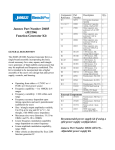
GETTING STARTED GUIDE MODEL 52771 4−Channel 1 GHz D/A with Interpolation Filter Onyx® Family VPX Board Setting the Standard for Digital Signal Processing Manual Part Number: 820.52771 Rev: 1.2 - June 17, 2015 Pentek, Inc. One Park Way Upper Saddle River, NJ 07458 (201) 818-5900 www.pentek.com Page 2 Mo d e l 5 2 7 7 1 G e t t i n g S t a r t e d G u i d e Manual Revision History Date Revision Comments 4/13/15 6/9/15 6/17/15 1.0 1.1 1.2 Initial Release. Revised What’s in the Box? and Installing the Hardware to note that two VPX slots are required. Removed Option 703. Added Pentek model numbers for terminator board and 26−pin socket. Copyright Copyright © 2015, Pentek, Inc. All Rights Reserved. Contents of this publication may not be reproduced in any form without written permission. The Linux kernel is Copyright © by Linus B. Torvalds, under the terms of the General Public License (GPL). Trademarks Pentek, Cobalt, GateFlow, and ReadyFlow are registered trademarks of Pentek, Inc. OpenVPX is a trademark of VITA. Linux is a registered trademark of Linus B. Torvalds. Microsoft and Windows are trademarks or registered trademarks of Microsoft Corporation. PCI Express and PCIe are registered trademarks of PCI− SIG. Xilinx, Virtex−7, Foundation ISE, iMPACT, and Platform Cable USB are registered trademarks of Xilinx Inc. Printed in the United States of America. Model 52771 Getting St arted Guide Page 3 What’s in the Box? Your shipment of Pentek Model 52771 should include the items on the following list. If anything is missing or damaged, contact Pentek immediately at (201) 818−5900. Please save the shipping container and packing material in case reshipment is required. Quantity 1 Part Number Description 002.52771 Model 52771 board (consisting of the Pentek Model 71771 mounted on the Pentek 5201 carrier) 1 002.71504 Terminator boarda 1 004.71605 JTAG board 2 385.30150 Screws for JTAG board 1 807.71605 Instruction sheet for JTAG board 2 356.00015 Shorting plugs 3 353.02607 26−pin socket for ribbon cable (sync)b 2 feet 378.62602 26−conductor ribbon cable, 30GA 025 (sync) 2 356.00015 Shorting plugs 1 900.10153 Hex key, 3/32” (option 763 only) 1 808.52771 Instruction Manual Kit (all included manuals) a. To purchase, use Pentek Model 2140-999. b. To purchase, use Pentek Model 2140-998. The list above includes all the standard parts that are shipped with Pentek Model 52771. The options for this product are described in this Getting Started Guide, the Pentek Model 52771 Installation Manual. NOTE: Model 52771 requires two VPX slots: one in which to install the Model 52771 assembly and a vacant slot to the right of it, required to accommodate the JTAG board. NOTE: If your Model 52771 has Option 741, you must use a 5HP width (1") VPX slot. Rev. 1.2 Page 4 Model 52771 Ge t t ing St a rt ed G uid e Introduction This document describes the Pentek Model 52771 Onyx® Family VPX board, its associ− ated software, what to consider before installation, and installation steps. Before You Begin: Description of Hardware Pentek’s Onyx® Family Model 52771 is a multichannel, high−speed analog data con− verter suitable for connection to HF or IF ports of a communications or radar system. Using the VPX 3U card format, Model 52771 includes four digital output interpolators and four digital−to−analog converters. Model 52771 consists of one Pentek Model 71771 XMC module mounted on a Pentek Model 5201 XMC 3U VPX carrier, assembled and tested as a single board. It is ready to plug into a chassis with a single 3U VPX slot. Refer to the Model 71771 Operating Manual (800.71771), along with the Model 52771 Installation Manual (800.52771) for a complete description of the Model 52771 hardware operation and programming. Before You Begin: Consider the VPX Backplane The Pentek Model 5201 carrier is configured in accordance with the VITA 65 OpenVPX™ standard, which defines VPX Slot Profiles for various signal connections. Before installing Model 52771, you will need to know or consider the following: Is your VPX backplane connection x4 or x8 PCIe? VPX P0 is pinned out in accordance with the VITA 46.0 VPX Baseline Standard. VPX P1 Slot Profiles are as follows: • SLT3−PAY−1F (without Option 105) has one Fat Pipe Data Plane (x4 PCIe interface). (Note that without Option 105 the Expansion Plane is no connects.) • SLT3−PAY−1F2F (with Option 105) has one Fat Pipe Data Plane (x4 PCIe interface), and two Fat Pipe Expansion Planes (x8 user−defined). VPX P2 has 24 user−defined differential pairs (with Option 104 only). Ensure that the VPX chassis has enough cooling and power capabilities for the number of installed modules. For more details, refer to the Model 52771 Installation Manual. Rev. 1.2 Model 52771 Getting St arted Guide Page 5 Before You Begin: Jumper and Switch Settings As shipped from the factory, all jumpers and switches are set in default positions on the Pentek Model 52771. The default operating parameters they select may or may not meet your requirements. Therefore, consider the following before installation: Pentek Model 71771 XMC Module Switch SW1 − FPGA Configuration When you install Model 52771, you may need to set DIP switch SW1 on the 71771 XMC module (which controls FPGA configuration) based on the characteristics of your host bus. Therefore, you will need to consider the following before you begin installation: • FLASH memory write protect/write enable • PLX PCIe switch maximum speed select • Select boot configuration at power on • PCIe clock select • P16 clock select • JTAG source select • GateXpress® disable (GateXpress is the FPGA−PCIe configuration manager for loading and reloading the FPGA) For example, Switch SW1−2 allows you to change the maximum speed of the PLX PCIe switch from Gen 3 (the factory default) to Gen 2. To preview the DIP switch settings you’ll need to make, refer to Section 2.4 of the Model 52771 Installation Manual. NOTE: The Model 71771 XMC module is shipped to boot with the Gen 3 x8 PCIe default FPGA code. However, the Model 5201 VPX carrier limits the default of the Model 52771 to Gen 3 x4. Pentek Model 5201 VPX Carrier Jumpers XMC JTAG: Jumper block JB1 includes or bypasses the 71771 XMC as part of the JTAG chain from the Pentek JTAG connector (J5). XMC Reset Source: Jumper block JB3 selects the source of the reset signal sent to the XMC interface (VPX SYSRESET or Board Power On). XMC MVMRO: Jumper block JB4 enables/disables MVMRO (XMC Write Prohibit) for the XMC interface. To preview the jumper settings you’ll need to consider for the 5201 carrier PCB, refer to Section 2.6 of the Model 52771 Installation Manual. NOTE: To access all jumpers, you must remove the XMC module from the VPX carrier, as described in Section 2.3 of the Model 52771 Installation Manual. Rev. 1.2 Page 6 Model 52771 Ge t t ing St a rt ed G uid e Before You Begin: Jumper and Switch Settings (continued) Pentek Model 5201 VPX Carrier Switches Clock Driver Operation: DIP switch SW1 selects modes for the XMC interface clock drivers. SW1 sets the following functions: clock power down, SRC stop, PLL bypass, and PLL bandwidth. XMC Geographic Address: DIP switch SW2 selects the Geographic Address bits (GA0, GA1, GA2) for the XMC site interface. To preview the DIP switch settings you’ll need to consider for the 5201 carrier PCB, refer to Section 2.7 of the Model 52771 Installation Manual. Before You Begin: Description of Software Board Support Software for the Pentek Model 52771 XMC Pentek’s ReadyFlow® Board Support Packages (BSP) contain software support for Model 52771. This includes a device driver for Model 52771, plus the ReadyFlow Board Support Library data structures and routines. The following available BSPs allow high−level programming for various workstation platforms. Refer to the User’s Guide indicated for each platform. Note that the user’s guides for Model 71771 also support Model 52771. • Model 4994A Option 167/671/771 ReadyFlow BSP for Linux® (816.71670) • Model 4995A Option 167/671 ReadyFlow BSP for Windows® (815.71670) Pentek’s ReadyFlow® Board Support Libraries contain a set of C−language routines for Model 52771. Refer to the Programmer’s Reference for Model 71771 (801.71770). Note that this Programmer’s Reference also supports Model 52771. Software for the FPGAs The FPGA is supported with a Pentek GateFlow® FPGA Design Kit. The GateFlow Design Kit (Model 4953−167/671) facilitates user−installed FPGA functions using the Xilinx® Foundation ISE® tool suite. The FPGA Design Kit allows the user to modify, add to, or replace the default logic functions within the FPGA with functions of his or her own definition. Note that GateFlow is a very specialized software package intended for users with experience in FPGA logic programming. This package may not be required if your application needs are met with the Pentek−default FPGA code. Refer to the following GateFlow software documentation: Pentek Model 4953−771 User Manual: Pentek Onyx Model 71771 GateFlow User Manual (807.71171). Note that the manual for Model 71771 also supports Model 52771. Rev. 1.2 Model 52771 Getting St arted Guide Page 7 Before You Begin: Consider the Product’s Options Timing and Synchronization The following timing and synchronization options are available for Model 52771’s D/A converter (all input/output signals are the same as defined for Model 71771): • External sample or reference clock: Received from the front panel SSMC connector labeled CLK IN. The external clock signal must be a sine or square wave, 0 to +10 dBm, AC−coupled, into 50 ohms. This input accepts a 100 to 1250 MHz sample clock or a 0 or 200 MHz reference clock. This input can be selected as the sample clock for the D/A converters using the CLK SEL bits in Sync Bus Control Register 1 (see the Model 71771 Operating Manual). This clock is input to a CDCM7005 Clock Synthesizer that generates separate internal clocks, each programmable as sub−multiples of the input frequency. The external clock input can provide a separate reference clock for synchronizing the CDCM7005 Clock Synthesizer. See the Model 71771 Operating Manual for details. • Onboard crystal oscillator: Alternately, the sample clock can be sourced from an onboard programmable voltage−controlled crystal oscillator (VCXO). In this mode, the front panel SSMC connector can be used to provide a reference clock for synchronizing the internal oscillator. • Two Sync 19−pin connectors: The front panel has two Sync 19−pin connectors, labeled SYNC A and SYNC B, which provide separate sync and gate inputs for the two internal sync buses. Sync Bus A is the timing bus for DAC3484 #1; Sync Bus B is the timing bus for DAC3484 #2. These pins are differential 2.5V CML input signals. The SYNC A connector provides a differential 2.5V CML external clock input. This input can be selected as the sample clock for the D/A converters using the CLK SEL bits in Sync Bus Control Register 1 (see the Model 71771 Operating Manual). The SYNC A connector also includes TWSI (I2C) bus pins for controlling an external sync module (Pentek Model 7192). Use the TWSI Port 1 Registers (see the Model 71771 Operating Manual) to access the 7192 module with these pins. The mating 19−pin connector is Pentek part # 353.00701. The Model 71771 Operating Manual provides a table showing the pin configuration for both SYNC connectors. • External trigger input: The front panel has one SSMC coaxial connector, labeled TRIG, for input of an external gate or trigger TTL signal. The trigger input can be used as a gate or trigger for D/A signal processing using the GATE B RCV SRC bits of the Sync Bus Control Register 2 (see the Model 71771 Operating Manual). Rev. 1.2 Page 8 Model 52771 Ge t t ing St a rt ed G uid e FPGA Digital Interfaces The Model 71771 XMC includes a Xilinx Virtex−7 FPGA for signal interfaces and pro− cessing. The FPGA is pre−configured to provide signal acquisition buffering functions. This FPGA also provides board interfaces including PCIe and XMC. The FPGA is factory programmed by Pentek to implement the standard signal process− ing and control functions specified in the Model 71771 Operating Manual. The Pentek GateFlow® FPGA Design Kit facilitates integration of user−created IP with the factory shipped functions. Following are the options for custom I/O: Option 104 − PMC Connector The 5201 VPX carrier provides one 64−pin PMC connector, designated J14 on the carrier PCB. These pins are directly wired from PMC J14 to the VPX P2 connector for user I/O. Option 104 for the 71771 provides 48 pins (24 differential pairs) defined as 'User I/O' from the FPGA to PMC connector P14. These connections are programmed for low− voltage differential signals (LVDS) in the default FPGA configuration. Refer to the Model 71771 Operating Manual for description of these signals. Option 105 − XMC Connector The 5201 VPX carrier provides two XMC connectors, designated J15 and J16 on the carrier PCB. J15 provides one x4 PCI Express link between the XMC and the carrier. J16 provides one x8 or two x4 serial links between the XMC and the carrier for 71771 Option 105 gigabit serial I/O. The 5201 VPX carrier routes these data links from the XMC J15 and J16 connectors to the VPX P1 connector. Rev. 1.2 NOTE: The P14 signals can be configured in the FPGA as either LVDS or LVTTL but in either case are limited to 2.5V for the VX330T, or 1.8V for the VX690T, and also cannot be driven with a negative voltage. NOTE: Refer to Section 2.9.4 of the Model 52771 Installation Manual for the pin mapping of the VPX P1 connection and Section 2.9.5 for the pin mapping of the VPX P2 connections. Model 52771 Getting St arted Guide Page 9 FPGA Configurations Following are the Xilinx Virtex−7 FPGA options for the Model 71771 XMC module: Option 073 is a Xilinx XC7VX330T−2 FPGA Option 076 is a Xilinx XC7VX690T−2 FPGA Model 71771 is shipped with a default FPGA configuration on FLASH memory. Model 71771 loads the FPGA configuration from FLASH memory at power−up. Up to four FPGA configurations can be stored in FLASH, identified as Version 0, Version 1, Ver− sion 2, and Version 3. The default FPGA configuration is located in the Version 0 space. The other three positions are empty. The 71771 is shipped with the FPGA configuration SW (SW1-2) set to ON, which sets the board’s maximum speed to Gen 3 x8. However, the Model 5201 carrier limits the number of lanes to x4. The board can negotiate down to Gen 2 or Gen 1 x4, as needed. For more information, refer to Section 2.4 in the Model 52771 Installation Manual. Documentation Required for Installation NOTE: Some manuals are used for more than one Pentek product. The manuals listed below are all used for Model 52771. • Pentek Model 52771 Installation Manual (800.52771): Describes the installation and connections for Model 52771. • Pentek Model 71771 Operating Manual (800.71771): Describes the operation and programming of the Model 71771 XMC module (a component of Model 52771). • Installation and Getting Started Guide for the Pentek ReadyFlow software version for the workstation platform you’re using (815.71670 for Windows, 816.71670 for Linux) • Pentek Model 4953−771 User Manual: Pentek Onyx Model 71771 GateFlow User Manual (807.71771) Rev. 1.2 Page 10 Model 52771 Getting Started Guide Step 1: Unpacking and Inspecting the Unit After unpacking, inspect the unit carefully for possible damage to connectors or com− ponents. Refer to page 3 for a list of what should be in the box. If anything is damaged or missing, contact Pentek immediately at (201) 818−5900. Please save the shipping container and packing material in case reshipment is required. Step 2: Checking the Switch Settings At the factory, all DIP switches on the Model 52771 are installed in default positions. The default parameters selected may or may not meet your requirements. As described above in Before You Begin: Jumper and Switch Settings, the switches control various configuration settings. Before installing Model 52771, review Sections 2.4, 2.7, and 2.8 in the Model 52771 Installation Manual to determine whether you need to change any settings. NOTE: You should only change the switches that are described in the Model 71771 Operating Manual and Model 52771 Installation Manual − all others are reserved for factory test and setup purposes only. Step 3: Installing the Hardware Model 52771 is designed to operate in VPX systems. To install Model 52771, follow the procedure in Section 2.11 (Installing the Model 52771 in a VPX Card Cage) in the Model 52771 Installation Manual. Rev. 1.2 NOTE: Model 52771 requires two VPX slots: one in which to install the Model 52771 assembly and a vacant slot to the right of it, required to accommodate the JTAG board. NOTE: If your Model 52771 has Option 741, you must use a 5HP width (1") VPX slot. NOTE: The JTAG PCB on the Model 52771 board (on the Model 71771 XMC module) is used for downloading new FPGA configuration code. If you do not plan to use the JTAG PCB, you can remove it before installing Model 52771. If you do plan to use the JTAG PCB, you should remove it before you deploy the Model 52771 board. Model 52771 Getting St arted Guide Page 11 Step 4: Installing the Cabling Connect cables for the analog signal outputs required by your application to Model 52771’s front panel SSMC connectors. These are labeled OUT 1, 2, 3, and 4: one for each DAC3484 output. OUT 1 and 2 are the A and C outputs respectively from DAC3484 #1; OUT 3 and 4 are the A and C outputs respectively from DAC3484 #2. The other cabling you install on Model 52771’s front panel depends on how you want to handle timing and synchronization (see Timing and Synchronization). Step 5: Installing the Software ReadyFlow Software Pentek's ReadyFlow Libraries are software packages designed to provide software development tools for specific Pentek products on specific operating systems or plat− forms. The installation procedure is different for each platform: Linux − The installation steps can be summarized as follows: • Installing ReadyFlow in a Linux system • Installing WinDriver (required to run example programs) • Building the ReadyFlow example programs • Building the ReadyFlow board support libraries For details, refer to Chapter 2 of the Model 4994A Option 167/671 User’s Guide (816.71670). Windows − You must install the Pentek ReadyFlow package BEFORE you attempt to boot Model 52771 under Windows. The installation steps can be summarized as follows: • Installing ReadyFlow in a Windows system • Initializing the hardware in Windows (responding to the New Hardware Wizard) • Building the ReadyFlow example programs • Building the ReadyFlow board support libraries For details, refer to Chapter 2 of the Model 4995A Option 167/671/771 User’s Guide (815.71670). Rev. 1.2 Page 12 Model 52771 Getting Started Guide GateFlow FPGA Design Kit The following software and hardware is required to use the GateFlow FPGA Design Kit: • Xilinx’s Foundation ISE (Version 12.2 or later). • Flashload Utility: This utility is supplied with the ReadyFlow software, but used with the GateFlow FPGA Design Kit as part of the process for implementing a project. The flashload utility reads a .mcs file, creating a binary image that is loaded into FLASH memory on the Model 71771 XMC module. • Pentek Model 71605 JTAG PCB: This JTAG adaptor, which comes already installed on the Model 71771 XMC module, is used for downloading new configuration code. After completing the development of your changes to the standard Pentek factory− supplied configuration, you should remove the JTAG PCB. • Xilinx’s Platform Cable: To connect to your development computer system you will need one of the following two cables, purchased from Xilinx: • Platform Cable USB (DLC−9, Xilinx part # HWUSB−G) • Platform Cable USB II (DLC10, Xilinx part # HWUSB−II−G) The Platform USB cable connects to a USB port on your development computer system, and thus carries its own 5V supply connection. The other end of both cables terminates in a pod, which contains a shrouded connector for a 14−pin, 2 mm pitch ribbon cable. The ribbon cable is included with the shipment of both Xilinx pro− gramming cables. To install the FPGA Design Kit for Model 52771’s Processing FPGA, copy the \GateFlow folder on the DVD−ROM to the root directory of the C: drive of the system you’ll be working on. Unzip the archived project files. The directory structure of the GateFlow DVD−ROMs mimics that of the development system upon which the original projects were created. We recommend that you copy the \GateFlow folder on each DVD−ROM to the root directory of the C: drive of the sys− tem you’ll be working on, such that the original, absolute pathnames of all files in the included project are maintained. Full details for installing the FPGA Design Kit are provided in Chapter 1 of the Gate− Flow user manuals listed in Documentation Required for Installation. Details about using flashload to download the .mcs file into the FLASH memory are provided in Chapter 2 of the GateFlow user manual. Rev. 1.2 Model 52771 Getting St arted Guide Page 13 Step 6: Using the Software ReadyFlow Software The User’s Guide for each ReadyFlow BSP provides instructions for using the Ready− Flow software. Chapter 3 provides the following: • Introduction to ReadyFlow − Provides an overview of how the software is used. • Using ReadyFlow − Provides details about using ReadyFlow, along with a modified code snippet from the example program. • Using Linked Lists − Describes how to set up DAC Output Controller Linked Lists and includes a code snippet from an example program. Chapter 4 describes the ReadyFlow data structures and routines that access the Linux or Windows device driver functions. Chapter 5 describes Command Line use and operation. GateFlow FPGA Design Kit Chapter 2 of the GateFlow User Manual covers procedures for implementing a project: • Using Your GateFlow FPGA Design Kit with Xilinx’s Foundation ISE Software • Preparing for a New FPGA Configuration • Transferring Configuration Data to the Model 71771 The GateFlow FPGA Design Kit includes test bench files and simulation projects that functionally simulate many operations of Model 52771, when the FPGAs are config− ured with their factory default configurations. Details are provided in Chapter 3 of the GateFlow User Manual (see Documentation Required for Installation). We recommend that before attempting any operational modifications of the default FPGA design, you should become very familiar with the board’s performance when operated with the default design. Once you are comfortably familiar with the default operation, we recommend that your first project with the FPGA design kit should be to re−compile the default code with one very simple change (the contents of the read− only FPGA Revision registers), and re−configure the FPGA with the re−compiled con− figuration file. (Refer to Chapter 2 of the GateFlow User Manual for details.) If you discover that you can use the entire default design for the FPGA, and simply need to add another function or two, Table 1−2 in Chapter 1 of the GateFlow User Man− ual will help you to determine how much of the FPGA’s resources remain available for your use. Rev. 1.2 Page 14 Model 52771 Getting Started Guide Documentation for This Product Any of the documentation listed below that is not supplied with the Model 52771 can be found at http://pentek.com. Product Documentation Part No 800.52771 800.71771 801.71770 807.71771 809.7x771 815.71670 Type / Description Installation Manual - Model 52771 4-Channel 1.25 GHz D/A with Interpolation Filter VPX Board Operating Manual - Model 71771 4-Channel 1.25 GHz D/A with Interpolation Filter XMC Module Programmer's Reference - ReadyFlow Board Support Libraries for Models 71771 User’s Manual - Model 4953-771 Design Kit for FPGA on the Model 71771 Supplemental Manual - Vendor Data Sheets for Model 7x771 Series Operating Manuals User's Guide - Model 4995A Option 167/671/771 Windows ReadyFlow BSP for Models 71670, 71671, and 71771 User's Guide - Model 4994A Option 167/671 Linux ReadyFlow BSP for Models 71670 and 71671 816.71670 Other Technical Documentation Catalogs: • • Pentek Product Catalog Product Selection Guide: http://www.pentek.com/selectguide/SelectGuide.cfm Handbooks: • • • • Critical Techniques for High−Speed A/Ds In Real−Time Systems High−speed Switched Serial Fabrics Improve System Design Putting FPGAs to Work For Software Radio Software Radio Handbook Receive the Latest Information with YourPentek To receive automatic notification about updates to this product’s documentation, set up a YourPentek profile at http://www.pentek.com/go/ypmanual. YourPentek will also notify you of any lifecycle changes for this product. Rev. 1.2