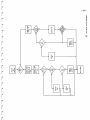
1
TEXT TELL
TECHNICAL MANUAL
PX-1000 PXP40
IB!K|
-1SECTION A: PX1000
CONTENTS
K )
1.
Page
GENERAL
1.1
1.2
2.
I N F O R M AT I O N
2
Product
Description
S p e c i fi c a t i o n s
2
3
THEORY
OF
3.
O P E R AT I O N
SERVICE
3.1
D
i
s
a
s
3.2Calibration
3.3
Te s t
4.
s
16
emb1y/As
s
emb1y
Procedure
R E PA I R
4.1
4.2
4.3
Int
Logic
5.
5
16
17
18
22
roduct
Modular
ion
Board
A P P L I C AT I O N S
22
22
24
35
5.1
C-M\IL
35
5.2
Company
Message
Center
35
5.3 Connection to Moving Message Displays 36
6.
ACCESSORIES
6.1
6.2
Standard
Optional
37
37
APPENDICES
38
Module
Replacement
List
Component
Layout
Diagrams
Component
Listing
7.4
Schematics
38
39
42
47
7.
pif.
7.1
7.2
7.3
■*
-
SECTION
B:
PXP40
1.
^
2.
37
GENERAL
THEORY
OF
50
O P E R AT I O N
52
3.
SERVICE
56
4.
APPENDICES
60
ist
l^t
-2R|
CHAPTER 1
GENERAL INFORVIATION
1.1 PX1000 PRODUCT DESCRIPTION
T E X T T E L L ' s P X 1 0 0 0 , t h e P o c k e t Te l e x i s a p o c k e t a b l e d a t a
communications unit, for creating and sending/receiving text.
Te x t c a n b e c r e a t e d u s i n g t h e s t a n d a r d Q W E R T Y k e y b o a r d , a n d s t o r e d
i n t h e u n i t ' s m e m o r y. T h e m e m o r y w i l l h o l d u p t o 7 , 4 0 0 c h a r a c t e r s ,
or 4 to 5 pages of standard A4. The text is viewed on a single line
o f 4 0 c h a r a c t e r s L i q u i d C r y s t a l D i s p l a y. I n b u i l t i n t h e u n i t i s a n
e a s y t o u s e , y e t s o h i s t i c a t e d w o r d p r o c c e s s o r.
Te x t c a n b e s e n t a n d r e c e i v e d b y t e l e p h o n e u s i n g t h e u n i t s o n
board simplex acoustic modem.
A l s o , t e x t c a n b e t r a n s f e r r e d t o a p r i n t e r o r c o m p u t e r, v i a a n
RS232C compatible serial port. Via this port also, text can be
r e c e i v e d f r o m a c o m p u t e r, o r o t h e r d a t a c o m m u n i c a t i o n s d e v i c e .
The unit is powered from an internal rechargeable battery pack, which
i s c h a r g e d f r o m a n e x t e r n a l a d a p t o r. T h e u n i t w i l l o p e r a t e f o r m o r e
t h a n fi v e h o u r s a f t e r a f u l l r e c h a r g e . T h e m e m o r y c o n t e n t s a r e k e p t
as long as the battery pack is charged.
There are visual indications on the LCD of the quality of telephone
r e c e p t i o n , t h e a m o u n t o f m e m o r y u s e d , w h e n t h e b a t t e r y p a c k i s l o w,
as well as other text information.
There is also an audio input/output audio socket which can be used
f o r s t o r a g e a n d r e t r i e v a l o f d a t a f r o m a s t a n d a r d t a p e r e c o r d e r.
There are different versions of the PX1000 available. The basic
unit is the Encrypt version which contains the extra function
e n a b l i n g t e x t t o b e e n c r y p t e d a c c o r d i n g t o a k e y, w h i c h i s s e l e c t e d
b y t h e u s e r. T h e o r i g i n a l t e x t , o n c e e n c r y p t e d , i s p r a c t i c a l l y
i m p o s s i b l e t o r e t r i e v e w i t h o u t k n o w l e d g e o f t h e e x a c t k e y.
The Calc version has, instead of the encrypt function, the
possibility to do basic arithmetic calculations.
R§
i ^
P5
i
1
1.2 SPECIFICATIONS
Genera 1
Dimensions Lenght
Height
Width
225 mm
85 mm
29 mm
Weight
450 g
Operating Temperature Range
Humidi ty Range
-10 C to +40 C
0-95% Rh
Storage Temperature Range
-25 deg. C to 55 deg. C
B^l
Techn i ca1
Power Supply
Power Consumption
Battery Charge Current
Ulffl^
Bat tery Li fe
internal rechargeable 6V battery
rechargeable from external 12V DC
adaptor.
< 150 uA unit off
< 30 mA norma 1 use
<" 50 mA transmit/receive mode
50 mA h igh charge
<2 mA trickle charge
>5 hrs. (normal use) after full
recharge
f fl m )
Memory capacity
fffiwj
8k (7.4k available to user)
i*a
Modem
Modulation Standard
Frequencies
Baud Rates
FSK CCITT V.23 mode 1, 600 Bd.
MARK 1300 Hz, SPACE 1700 Hz
300, 600 and 1200 selectable from
keyboard
1 start-bit, 7 data-bits, LSB
fi r s t , 1 p a r i t y - b i t , 2 s t o p - b i t s
Even
Data Format
Par i ty
Header
Transmission starts with 0.5 sec.
MARK, followed by 16 Null-Bytes,
(ASCII 00) at the selected baud
rate, 0.8 sec MARK, and 4 Null
bytes
Set at factory to maximum level
a l l o w a b l e b y Te l e p h o n e A u t h o r i t y
in country of sale.
<-30dBm.
Speaker Output level
Receiver Sensitivity
^
f^s
Serial Port
Vo 1 t a g e L e v e l s
Baud Rate
Data Format
Input
Output
MARK -3 to -15V, SPACE 3 to 15V
MARK -5V (+-20%),SPACE 5V (+-20%)
1200 Bd
1 start-bit, 7 data-bits, LSB
fi r s t , 1 p a r i t y - b i t , 2 s t o p - b i t s .
Even
Input
Output
5.0V p-p max.
1.6V p-p in 120 ohm
120 ohm.
FSK CCITT V.23 600 Bd. Standard
Par i ty
ra
Audio Socket
Vo 1 t a g e L e v e 1 s
Input impedance
Signal Format
™
fi
^
fS
™
f5
™
fJ
-5CHAPTER 2
PX1000 THEORY OF OPERATION
Jpl
The following is a detailed technical description of the theory of
o p e r a t i o n o f t h e P X 1 0 0 0 , Ve r s i o n H .
PCWER SUPPLY
JP!
T h e P X 1 0 0 0 d e r i v e s i t s p o w e r f r o m a b a t t e r y p a c k c o n t a i n i n g fi v e
rechargeable, Ni-Cd cells, connected in series, each with a nominal
v o l t a g e o f 1 . 2 V. T h i s g e n e r a t e s a n o m i n a l v o l t a g e o f 6 V D C a t t h e
battery inputs, pins 1 and 2, on connector J5.
This voltage is applied directly to IC7, which is a QUAD-NAND,
74HC00. This IC controls the power on/off to the remainder of the
ci rcui t.
W h e n t h e u n i t i s o f f , p o w e r i s t u r n e d o n b y p r e s s i n g t h e k e y O N / S T O P.
This key is connected to the RESET input of a bi-stable made up of
two NAND gates of IC7. In the off state, the output on pin 3, IC7 is
l o w. W h e n O N / S T O P i s p r e s s e d , t h i s o u t p u t g o e s h i g h , t u r n i n g o n b o t h
transistors, Tl and T2, via current-1imiting resistors R8 and R18.
Because of zener diode, Zl, which is 5V7, the voltage on the emitter
o f T l , i s n o w 5 V. T h i s i s V C C . P u l l - u p r e s i s t o r , R 7 , h o l d s t h e
bi-stable in set state. The bi-stable is reset by a low pulse from
MPU port P22, which turns off Tl and T2.
A v o l t a g e c o n v e r t o r, I C 6 ( 7 6 6 0 ) , i s n o w p o w e r e d u p , a n d g e n e r a t e s a
voltage of approximately -5V at its output, pin 5, using reservoir and
pump capacitors, C6 and C7.
The main RAM, IC4 (6264), is powered directly from the battery pack,
via diodes D3 and D4, which ensure the correct supply voltage for
this IC.
f9i
-6BATTERY CHARGE CCT.
The battery charge circuit consists of a dual voltage sensor IC, a
7665, (IC8), and a current drive circuit consisting of transistors m
T 3 , Ti l a n d T 1 2 , a n d r e s i s t o r s R 3 7 , a n d R 4 2 . T h e o p e r a t i o n o f t h e
circuit is such that discharged batteries are initially charged at a
h i g h r a t e o f 0 . 3 C , w h e r e C i s t h e b a t t e r y c a p a c i t y, w h i c h i s 1 7 0 m A h , m
u n t i l t h e y r e a c h a s p e c i fi c v o l t a g e , o f 7 . 5 V , a t w h i c h p o i n t t h e r a t e
is reduced, to a trickle rate, of less than 0.01C.
When the charger is inserted, 12VDC appears at pin 38 of the hybrid.
The low level of the battery voltage is detected at SI of IC8, which ;
turns on T3, via output OUT1 (T3 is actually turned on by pull-up
R43, as OUT1 is now high-impedance). This, in turn, turns on
transistors Til and T12, via current-1imiting resistor, R41. Til «*
s h o r t s o u t r e s i s t o r R 4 2 , s o t h e c u r r e n t fl o w i n g i n t o t h e b a t t e r i e s
is equal to 0.7V divided by the value of R37, which is 13 ohms,
giving a charge current of approximately 50 mA. Diode D8 prevents m
reverse current through this cicruit from the batteries. Capacitor
C5 provides power supply decoupling.
A f t e r a s h o r t w h i l e , t h e b a t t e r y v o l t a g e w i l l r i s e t o 7 . 5 V, w h i c h ,
when detected by S2 of IC8, will cause T3 to turn off ( by shorting m
i t s b a s e t o g r o u n d ) , a n d a l s o Ti l a n d T 1 2 . N o w t h e c h a r g e c u r r e n t i s
determined by the voltage accross R37 and R42 in series, giving a
current
of
approximately
1mA.
m
The actual level at which the high rate of charge switches out is
d e t e r m i n e d b y p o t e n t i o m e t e r, P I .
IC8 also has an output pin, OUT2 which gives an indication to the «
M P U w h e n t h e b a t t e r i e s a r e l o w, a n d n e e d r e c h a r g i n g . T h e l e v e l , a t
which this output switches, is set by the resistor network R12, R13 J
and R14; a low output indicating low batteries. Resistor R5 pulls
the
output
high,
when
the
internal
switch
is
off.
H
Inbuilt hysterisis in IC8 prevents output oscillation. This involves J
outputs HI and H2, which change state when the trip point is reached,
(BSS
thus, via RIO and Rl1, effectively changing the detection levels. The
voltage must reach the new level, before the output will switch again.
MPU CLOCK CIRCUIT
T h e h e a r t o f t h e s y s t e m i s t h e m i c r o p r o c c e s s o r, w h i c h , l i k e e v e r y
other MPU, must have a clock source from which to operate. ^j
The clock circuit for the micro is made up from a 4.0 IvHz parallel J
r e s o n a n t f u n d a m e n t a l c r y s t a l , AT c u t . T h i s , t o g e t h e r w i t h t w o
capacitors, CI and C2, provides a sine wave signal at the MPU pins m
X TA L a n d E X TA L , o f 4 M H z i n f r e q u e n c y. T h i s i s d i v i d e d d o w n i n t e r n a l l y
in the MPU, so that the system clock is 1MHz.
to
f^
p™j
. %f&\
-7MPU
r
W h e n V C C i s a p p l i e d t o t h e M P U , b y p r e s s i n g O N / S TO P a s d e s c r i b e d
above, the MPU comes out of reset, after a delay of 20mS, caused
by the RC network, R3 and C4.
The states of ports P20, P21, and P22 immediately after coming
out of reset decide in which mode the MPU will operate. P21 is tied to
ground, P20 is low because it is connected to the port of an IC which
i s p o w e r e d d o w n , a n d P 2 2 i s p u l l e d h i g h , v i a R 7 . C o n s e q u e n t l y, t h e M P U
o p e r a t e s i n t h e M u l t i p l e x e d M o d e . T h i s m e a n s t h a t t h e D ATA b u s i s
multiplexed with the lower 8 lines of the ADDRESS bus.
The MPU inputs NMI and STB are tied to VCC, and so, are always
inact ive.
The ON/STOP key is also connected to the external interrupt i/p, IRQ.
This input is pulled high by resistor R6, when the ON/STOP switch is
open. Diode D5 prevents battery voltage appearing on this input.
Diode D2 provides immediate reset of the MPU, on power down, by rapid
discharge of C4.
Switch SI, between MPU RST and GND, is included to provide the
facility to completely reset the system.
ADDRESS AND DATA BUSSES
As mentioned above, the data bus, and lower address bus are
*■ m u l t i p l e x e d . S o , t o b e a b l e t o s e p a r a t e t h e d i f f e r e n t s i g n a l s , t h e r e
i s oau pl au ttcsh ,o fI Ct 2h i s( 7 4l aHt C
37a
3 )r ,e uasl ewda yf so r etnhae b laeddd,r evsi sa opui n
t p u1t,s . w h i c h i s
*" The
ch
/Wl
#^)
tied to ground. These outputs are controlled by the address strobe
signal, AS, which is output from pin 39, of the MPU. When this
signal is high, the outputs will follow the inputs. When the signal
g o e s l o w, t h e o u t p u t s w i l l r e m a i n u n t i l t h e s i g n a l g o e s h i g h a g a i n .
The 8-bit data bus is connected to RAM,(IC4), ROM, (IC3), and the
Keyboard. The upper four data bits are connected to the LCD module.
The address bus is connected to RAM, ROM and to the Keyboard.
The upper two address lines, A14 and A15, are connected to the
d e c o d e r, I C 5 .
The system is an 8-bit data, 64K memory system.
w
Fi
-8DECODER
A decoder chip, IC5 (74HC138), is used to determine which part
of the circuit the MPU wishes to address at any one time. The
memory is divided into four equal parts, of which the following
locations are used by the program :
$0000
$0020
$0080
$0100
$2000
$4000
$4002
$8000
$8002
$E000
-
$001F Internal Registers
$007F External Memory space
$00FF Internal RAM
$1FFF Main External RAM
$3FFF not used
$4001 KEYBOARD
$7FFF not used
$8001 LQvl
$DFFF not used
$FFFF EPROM
The inputs to the decoder are A15, A14 and the E signal (system clock)
from the MPU.
Any time the MPU addresses a valid part of the memory map, the
r e l e v a n t o u t p u t w i l l g o l o w. O t h e r w i s e , a l l t h e o u t p u t s a r e h i g h .
EPROM
The program memory is contained in 8K EPROM, IC3 2764, and is
l o c a t e d a t a d d r e s s $ C 0 0 0 i n t h e s y s t e m m e m o r y. I t i s e n a b l e d w h e n
t h e i / p ' s G l , C a n d B , t o t h e d e c o d e r, a r e a s f o l l o w s :
Gl C
1 1
B
X
18?.
T h i s c o m b i n a t i o n w i l l b r i n g o u t p u t Y 6 l o w, w h i c h i s c o n n e c t e d t o t h e
chip enable i/p, CE, of the EPROM.
This occurs when anywhere in memory above $C000 is addressed.
Because only 8k Eprom is used, $C000 to $DFFF is redundant. When any
other place in memory is addressed, the EPROM is disabled, because CE
i/p is high, and so, its data o/p's are high-impedance.
Y^sr
Rj
Rj
-9RAM
IP!
R A M i s l o c a t e d a t a d d r e s s $ 0 0 0 0 i n m e m o r y, a n d t a k e s u p 8 K . T h i s
includes the RAM internal to the microproccessor which is 128 Bytes,
as well as the external RAM, which is an 8K HN6264, IC4. The external
RAM is used mainly for text storage, but also is used by the program.
The program uses up to 600 bytes, leaving 7.4K available for text
storage.
There are two chip select i/p's to the RAM IC, CS1 and CS2. CS1, which
i s a c t i v e l o w, i s u s e d b y t h e d e c o d e r t o a c c e s s R A M d u r i n g n o r m a l
running. In this situation, CS2, which is active high, must be high.
In power down mode, the contents of the RAM IC must be protected
from corruption, which could occur while the power to the MPU is
decaying, and its outputs are unpredictable. Power off is controlled
b y t h e M P U . B e f o r e c u t t i n g p o w e r , t h e M P U fi r s t b r i n g s o / p P 1 3 l o w ,
which is connected to CS2. Also connected to this pin is a pull-down
r e s i s t o r, R l , w h i c h e n s u r e s t h a t t h e R A M r e m a i n s d i s a b l e d u n t i l
power-up again.
During running mode, RAM is enabled when the inputs to the decoder are
as fol lows :
Gl C B
1 0 0
T h i s s i t u a t i o n o c c u r s w h e n t h e M P U a d d r e s s e s a n y l o a c t i o n i n m e m o r y,
b e t w e e n t h e l o c a t i o n s $ 0 0 0 0 t o $ 3 F F F.
Power to the RAM IC is fed directly from the battery voltage, to
VDD, pin 28, via diodes D3 and D4. This ensures that RAM cotents are
s a v e d , f o r a s l o n g a s t h e b a t t e r y v o l t a g e r e m a i n s a b o v e 5 . 9 V,
t h e o r e t i c a l l y. I n a c t u a l p r a c t i c e , t h e c o n t e n t s r e m a i n v a l i d f o r m u c h
lower voltage levels. Because of the low current consumption of the IC
i n s t a n d b y, r e s i s t o r R 1 7 e n s u r e s t h a t d i o d e s D 3 a n d D 4 a r e t u r n e d o n
fully to provide the required voltage drop from the battery voltage.
Capacitor C24 provides power supply decoupling.
Sffl
BSl
JP>
f™i
-10Pij
KEYBOARD
The keyboard is included on the memory map, b u t i s e n a b l e d s e p e r a t e l y
by the MPU, via output P16.
T h e k e y b o a r d i s r e a d i n t h e f o l l o w i n g m a n n e r. F i r s t a q u i c k s c a n i s
made to determine whether a key has been pressed. This involves
e n a b l i n g t h e k e y b o a r d b y b r i n g i n g P 1 6 l o w. I f n o k e y i s p r e s s e d , a l l
data lines will be high. A pressed key will cause one data line to go
l o w , v i a a c o m b i n a t i o n o f t w o o f r e s i s t o r s , R l t o R 1 6 . To i d e n t i f y
exactly which key has been pressed, each address line, A0 to A8,
i s b r o u g h t l o w i n d i v i d u a l l y, a n d t h e d a t a b u s r e a d a s a b o v e .
LCM
The Liqu id Crystal Display Module,the LCM, is custom designed for the
PX1000. I t i s a o n e l i n e X 4 0 c h a r a c t e r d i s p l a y , e a c h c h a r a c t e r
contai ne d i n a 5 x 7 d o t f o n t . A l s o o n t h e d i s p l a y a r e u p t o s e v e n
mi ni atur e fi x e d m e s s a g e s , w h i c h a r e u s e d t o i n d i c a t e t h e s t a t u s o f
c e r t a i n f u n c t i o n s t o t h e u s e r.
The LCM i s d r i v e n b y f o u r H D 4 4 1 0 0 L C D s e g m e n t / c o l u m n d r i v e r s a n d a
HD44780 d o t m a t r i x c o n t r o l l e r . T h e c o n t r o l l e r I C a l s o c o n t a i n s
characte r generator ROM, as well as character generator RAM, which
g i v e s t h e u s e r a b i l i t y t o d e fi n e u p t o 1 4 e x t r a c h a r a c t e r s .
T h e c o n t r a s t o f t h e L C D i s fi x e d .
The MPU c o m m u n i c a t e s w i t h t h e L C M v i a a t e n s i g n a l c o n n e c t i o n , J 2 .
This connection contains the four upper data lines D5 to D7, as
we 11 as t h e f o l l o w i n g :
+Vcc
-Vcc
GND
tm
power supply
™
i i
R/W
R/W signal from the MPU, which t e l l s t h e L C D c o n t r o l l e r
whether the MPU wants to WRITE t o , o r, R E A D f r o m , t h e L C M .
LCDE
active high enable signal from the decoder, via invertor j
o f I C 7 , a n d a b l o c k i n g d i o d e , D l a n d p u l l - u p r e s i s t o r, R 2 ^
which convert the high voltage output from IC5, which is
c o n n e c t e d d i r e c t l y t o t h e b a t t e r y, t o n o r m a l T T L l e v e l s .
Rs
o/p from the LCM to indicate to the MPU that it is ready to
recieve data and/or commands.
All data and commands for the LCM from the MPU, are sent in 4-bit
nibbles, via the upper four data lines, D5 to D7, in a two-byte
Commands'are written to location $8000, which access a write only
r e g i s t e r, w h i l e d a t a i s w r i t t e n a n d r e a d a t $ 8 0 0 1 .
All data for the operation of the display is saved and updated in the
LCD controller IC. The MPU only writes data when it wants to update
the display contents.
R)
- 11 MODEM
0St
fP>
The modem, IC9 TCM 3101, is an IC which basically converts digital signals
to analoge signals and vice-versa. The reason is such that digital
information from the MPU can be transformed into a signal which can be
transmitted over the telephone network. Because of the characteristics of
the telephone system, the digital signals are converted to audio signals,
with the two different digital states represented by two different
frequencies. This system is called Frequency Shift Keying. The modem in
the PX1000 is used in simplex mode, i.e it is either transmitting or
receiving. In transmit mode, digital data from the MPU o/p, P14, is fed
to the modem Transmit Digital I/P on pin 14. The data is internally
c o n v e r t e d t o a s i n e w a v e s i g n a l o n t h e T r a n s m i t A n a l o g u e O / P, p i n 11 . T h i s
signal is 1.6V p-p, and has a frequency of 1700Hz for a '0' i/p, and 1300
Hz for a '1' i/p. In receive mode, an audio signal appearing on the
R e c e i v e A n a l o g u e I / P, p i n 4 o n t h e m o d e m , i s c o n v e r t e d t o a d i g i t a l
signal at Receive Digital o/p, pin 8, and fed to the MPU i/p, P20. The
audio frequencies are derived from a clock, made up from crystal XT2, and
capacitors C9 and C10. The voltage level at the Carrier Detect Level i/p,
pin 10, determines what level the modem wi 1 1 detect an analogue signal
i/p. This level is set by the resistor combination R15 and R16, and
decoupler capacitor CI 1 Potentiometer P2, in combination with C12,
adjusts the distortion level of the received data, by varying the voltage
level on this pin. Power to the modem is controlled by T6, which is turned
on by the MPU output, Pll, via resistors R26 and R40 only when the modem
is in use. This reduces overall power consumption of the PX. T6 is in
turn fed from VCC by a seperate transistor T2, and not by Tl, because of
the rather high current current consumption of the modem circuit. Zener
diode, Z2, of value 5V6, ensures 5V to the modem, even though the battery
v o l t a g e m a y v a r y. T h i s i s n e c c e s a r y s o t h a t i / p ' s C D L a n d R X B r e m a i n
constant. Capacitor C8 provides power supply decoupling. The frequencies
used are of the CCITT Standard V23 for a baud rate of 600 Bd, regardless
of the i/p baud rate to the modem. The data can be in any of three
different speeds: 300, 600 or 1200 bits/s.
AUDIO OUTPUT AMPLIFIER
!S>
Analogue output from the modem IC, is fed through a complementary
driver buffer stage, consisting of Darlington pairs, T8 and T9 ,and
r e s i s t o r s R 3 1 a n d R 3 2 , b e f o r e b e i n g f e d t o t h e s p e a k e r. T h e s i g n a l
is ac coupled via capacitors, C20 and C21. R33 varies the actual
v o l t a g e a c r o s s t h e s p e a k e r, a n d s o , t h e o u t p u t v o l u m e l e v e l .
P o w e r t o t h e o u t p u t a m p l i fi e r i s s w i t c h e d w i t h t h e m o d e m b y t r a n s i s t o r
T7, via resistors R27 and R28.
-12AUDIO INPUT AMPLIFIER
Analogue input, picked up on the microphone, is fed first to the
limiting circuit D9, D10 and R35, then to the filter circuit, R34 and
C18, and then to the first of two amplifier stages, via ac coupler
C17.
The first is a transistor invertor type, with gain of 100, set by
resistors R38 and R39. The output is ac coupled by C25.
The second consists of an audio op-amp, IC10 TA7330, with gain of
100, determined by feedback circuit of R30, R48, C16 and C19. The
output from the op-amp is ac coupled by C14, then limited, by two
germanium diodes, D14 and D15, and resistor R47, and ac coupled again
by C23. This ensures a maximum i/p signal to the modem of 0.7v p-p,
which is specified for this IC.
Because, the modem is only concerned with the frequency of the signal,
possible clipping caused by these diodes will not effect performance.
IC10 is power supply decoupled by capacitor C13 and C15.
SERIAL
OUTPUT
CIRCUIT
The serial output circuit consists of transistor T5 and resistors R23
R24 and R25.
Serial data is fed from output P24 of the MPU, to the base of PNP
transistor, T5, via R24, such that a '0' on P24 turns on T5, and a '1'
turns it off. The emitter of T5 is connected to 5V, and the collector
to -5V, via resistor R25. Serial output is taken from the collector
of T5, via current limiting resistor, R26. The effect of the output
circuit is such that a '1' on P24, MPU, gives -5V at the output,
while a *0', gives +5V. These levels are compatible with the RS232C
Standard.
p«l
J
«
j
J
^
m
Ks
MP
SERIAL INPUT CIRCUIT
The serial input circuit consists of P23 of the MPU, R4, R11,D6, D7,
and Dll. It is used to indicate to the the MPU, whether an external
device is ready to receive data from the serial output. It is designed
for use with other RS232C Standard equipment.
The actual input pin is also used by the 12VDC battery charger. Diode
Dll prevents current flow into the serial input circuit when the
charger is inserted.
Diodes D6 and D7 limit voltage levels on the MPU to within accecptable
limits, even'when RS232C Standard voltages of up to 15V in
magnitude
appear
at
the
serial
input.
Resistor R19 is for current-1imiting, and R4 is a pull-up to VCC. ^
A zero, or negative voltage on the serial input pin, appears as 0 on
P23 of the MPU. A +5V, or positive voltage on the serial input pin
appears as a '1' on the MPU.
«
J
R
5
J
j
P"8
P^
m
m
■p
n
E
-13LED DRIVE CIRCUIT.
The LED is turned by two different methods; either directly under
r control of the MPU, and/or when the 12VDC battery charger is inserted.
t When being driven by the MPU, the circuit involved consists of MPU
output P17, transistor T4, resistors R20, R21, and R22, diode D13
« and the LED itself.
A '0' on the MPU output turns on T4, giving a high on its collector,
which drives the LED on, via cur rent-1imi ting resistor R22. A '1'
-> from the MPU will turn off the LED.
When the battery charger is inserted, the 12VDC drives the LED,
through the circuit involving T13, D12, R44, R45, and R46. Resistors
R44 and R45 provide bias for transistor T13, turning it on, which
P drives the LED on via current-1imiting resistor R46. Diodes D12 and
D13 act as blocking diodes to prevent either one of the LED drive
circuits from interference with the other.
p Both circuits are capable of operating together; when they do,the LED
burns brighter because of higher current.
T AUDIO TRANSDUCER
Audio input
m which acts as
in simplex
speaker at
and output to and from the unit is via an audio transducer
both microphone and speaker. Because the unit operates
mode only, this transducer will either be microphone, or
any one time.
AUDIO INPUT/OUTPUT SOCKET
m Audio signals can be input and output, to and from the PX directly,
as well as acoustically, via socket J4. When there is something
connected in this socket, the audio transducer is disconnected from
p t h e idevice
/ o c i r c to
u i t rthese
y, a n dcircuits.
signals are fed directly from the external
* RFI REDUCTION CIRCUITRY
Circuitry is included to reduce the amount of Radio Frequency
m Interference, which is associated with the high rate of activity
[ around the MPU and on the address and data lines.
Two methods of reduction are used. One is to actually reduce the
amount of noise on the power lines. This is done by the capacitors
C26 to C29.
The second method is to insert filters on the input and output
signals. These filters are made up from capacitors CI to C4 in
m conjunction with chokes LI to L6.
S^
-14DIFFERENCES
BETWEEN
H
VERSION
AND
F
VERSION
^
As well as the main differences, listed below, there are a few minor «
differences also :Some circuitry which is in discrete component form in version F is
on
the
Hybrid
on
version
H.
«|
T h e n u m b e r i n g o f c e r t a i n c o m p o n e n t s d i ff e r s b e t w e e n b o t h v e r s i o n s . J
Because of this, unless otherwise stated, the component numbers
m e n t i o n e d b e l o w , r e f e r t o t h e s c h e m a t i c f o r v e r s i o n F. < m
1. On the F version IC10, the audio input op-amplifier chip, is
a M51304L. Its operaton is similar to IC10, (TA7330P), on the H
version, except that its output is limited by an AGC (Automatic Gain
Control), instead of the germanium diodes as used in the H version.
^■^
2. On version F, the CDL level input to the Modem, IC9, is set by
potentiometer, instead of resistor divider, as on version H.
3. On Version F, the voltage sensor, IC8 is excluded. The battery
charge rate is constant, at 25mA, set by resistors R18 and R37 in
series. Transistor T3 is always turned on by pull-up resistor, R16
so
R17
is
shorted
out.
'
^
4. The 12VDC supply drives the LED via zener diode from cathode D8,
of
6V2,
and
cur
rent
1imiting
resistor.
^
5. There is no resistor from RAM VDD to ground, in version F. On the
H board this resistor ensures that diodes D3 and D4 are full biased,
making the supply voltage for the RAM closer to specification.
f ^ i
6. The RFI reduction circuitry, involving capacitors C26 to C29, is
not included in the F version.
1^1
. HK|
ffl&l
LCD MOOUL6
THXT TELL PXIOOO
* * 0 C H A R A C T E R O l S P L AY
e»LOCK DIAGRAM
mtmmmtfflttffl!?
CCHrWUHt— LCD DR.!VERS
K£Y&CkA*3> A5-SY
* W)
^,S^..^?A.RfiL O fi l C I b O A R D
LED
&ATTER.Y
T
IOSN
CHAQ6?
C0WT0OL.
O W POT
micro
power
J S U P P LV
POWeRCRF
P3C££SS0R
-On
V 2 3
MODdM
s
L<JJ
J.Mj*£FlEP
' W\
*.
RAM
6V
SERUL
<£ SfiRULlW
S€PM (. OUT
wni
a
a
□
□
6rdu k;o
ROM
nrm
B AT T E R Y
RACK
"J ON/ sropKcr
<IS|^
<
«
V D C
AUX
PORT
-16CHAPTER 3
SERVICE
(553'
3.1 DISASSEMBLY OF PX1000
The PX1000 can be dismantled, for repair and adjustment purposes, as
follows
:
•
(5*jj
1. Remove bottom housing by first unscrewing the six self-tap
cross-head screws, on the underneath side of the unit. Separate
the bottom housing from the remainder of the unit, by first lifting
the end nearest the audio socket, J4, and then sliding the other
end from around the power socket, J3.
2. Disconnect the battery pack/speaker from the main circuit by
slipping socket J5 from plug J5, on the logic board. The battery
pack is fixed to the bottom housing with adhesive, but can be
easily removed for replacement purposes. The speaker sits in a
Rr
groove in the rubber sealing ring, and be eased out with the aid
of a small flat top screwdriver or similar tool. Desolder the wires
from the speaker to seperate it completely from the unit.
The rubber accoustic sealing ring can be removed by slipping it ^
through
the
hole
in
the
housing.
J
3. Remove the logic board from the keyboard/LCM assembly by separating m
32-pin socket Jl, on the logic board from the 32-pin plug Jl, on
the keyboard PCB, using a small flat-head screw-driver.
4. To access the LCD module, first remove the instruction sticker from 1
the LCD cover. Unscrew the nine cross-head screws, and remove the "
LCD cover.
To separate the LCD module from the keyboard PCB, desolder the ten "1
contacts
of
the
fl e x i - P C B
from
the
LCM
PCB.
)
5 . To a c c e s s t h e r u b b e r k e y - p a d a n d k e y s , s n i p t h e t o p s o f f t h e * *■■
plastic pillars which hold the keyboard PCB to the unit, and lift
off the keyboard PCB. Replace the PCB by melting down the* pillars
over the PCB holes. (Because the pillars get smaller each time, «
this cannot be done too often.)
The flexi-PCB can be separated from the keyboard PCB by desoldering '
the ten contacts, as with the LCM PCB. To remove the flexi-PCB
f r o m t h e u n i t c o m p l e t e l y, i t m u s t fi r s t b e b e n t o v e r, a n d t h e n s l i d R
through the hinge.
RJ
P5
-173.2 CALIBRATION ADJUSTMENTS
The only adjustments which need to be done on the PX1000 are to two
potentiometers on the logic board. These adjustments are done before
t h e u n i t l e a v e s t h e f a c t o r y, b u t m a y, i n s o m e c a s e s , n e e d t o b e r e d o n e
because of slipping of the setting due to vibration etc.
The two pots, to be adjusted are different depending on whether the
b o a r d i s a n F o r H v e r s i o n . To a d j u s t b o t h , fi r s t r e m o v e t h e b o t t o m
hous ing.
Bill
Pot. P2 serves a similar function on both boards. Its purpose is to
m i n i m i s e t h e d i s t o r t i o n o n t h e r e c e i v e d m o d e m s i g n a l . To a d j u s t t h i s ,
either directly or accoustical couple another PX to the unit. Press
ON/STOP + D on the other unit. Press RCVE on the unit to be adjusted.
Place the probe of an oscilloscope on pin 8 of IC1. A square wave
TTL signal of 1200 Bd should appear on the scope screen. Adjust
potentiometer P2, such that the mark/space ratio of this signal is
equal.
Pot. PI on logic board F is used to set the CDL (carrier detect level)
on the modem IC. This pot. should be adjusted such that the voltage
level appearing on pin 10 of the modem, IC9, should be between 0.64
and 0.74 times the voltage VDD at pin 1 of the modem.
This pot. is replaced by a resistor divider network on the H version
logic board.
IP1
r
On logic board H, pot. PI is used to adjust the level at which the
b a t t e r y c h a r g e c u r r e n t r a t e c h a n g e s f r o m h i g h t o l o w.
T o fi x t h i s , fi r s t c o n n e c t a v a r i a b l e v o l t a g e s u p p l y t o c o n n e c t o r
J5 on the logic board instead of the battery terminals. Place a
v o l t m e t e r a c c r o s s t h i s s u p p l y. P l a c e e i t h e r a n o s c i l l o s c o p e o r s e c o n d
voltmeter at pin 1 of IC8.
Tu r n o n t h e u n i t , a n d k e e p i t o n b y p e s s i n g O N / S T O P + D .
I n c r e a s e t h e v o l t a g e s u c h t h a t 7 . 4 5 V a p p e a r s o n t h e fi r s t m e t e r .
Set PI to maximum anti-clockwise position. Now turn PI clockwise
u n t i l t h e v o l t a g e l e v e l o n t h e p i n 1 , I C 8 g o e s l o w. R e d u c e v o l t a g e
o n t h e p o w e r s u p p l y t o a b o u t 6 . 5 V, a n d t h e n i n c r e a s e s l o w l y u n t i l
t h e v o l t a g e a t p i n 1 , I C 8 g o e s l o w . T h e r e a d i n g o n t h e fi r s t m e t e r
s h o u l d n o w b e b e t w e e n 7 . 4 V a n d 7 . 5 V.
This pot. is not present on the F version logic board as IC8 is not
included in the circuit.
r&s!|i
-183.3 PX1000 TEST PROCEDURE
The following is a description of how the PX1000 should be tested, after ffl
repair work has been carried out, to ensure correct operation of the unit
The test procedure involves checking the operation of the main functions of the unit.
First carry out the tests ON/STOP + Z and ON/STOP + M, as described at trj
end of this section. Then check the operation of each part of the unit as
fol
lows.
<m
1. LCD
Type in one full row of 8's. Check the contrast of the display. Ensure
that the viewing angle is correct and that there is no flickering. Check
the operation of all dots and fixed messages.
2. KEYBOARD
Press "CAPS LOCK" ; LOCK should appear in the upper middle part of
the display.
Type in the following:
fWi
ABCDEFffllJKLMNOPQRSTLMVXYZ 1234567890-!% (Return)
abcdefghi jklmnopqrstuvwxyz
Make sure the proper character appears on the display for each key
pressed. Make sure there is a bleep as each character is pressed.
fiwffl* I
Press each of the following function keys in turn, and make sure of the
correct response to each key depressed. Press ON-STOP to cancel each
function each time.
Key
MARGIN
CODE
CALC
CLEAR ALL
DUMP
SEARCH
LEFT SHIFT + TEXT
TAB
RIGHT SHIFT + TEXT
INSERT
DELETE
<l
>
SHIFT + >
SHIFT + <
SHIFT + <?
SHIFT + Zi
Response on display
SET RIGHT MARGIN AT 40 + PRESS AGAIN
EN/DECRYPT TEXT 01 ? + PRESS AGAIN
*** CAN NOT CALCULATE ***
ERASE ALL TEXT ? + PRESS AGAIN
START 'RECORD' ON TAPE + PRESS AGAIN
SEARCH FOR + PRESS AGAIN
displays moves to next text
cursor moves to next tab point on display
displays moves back to previous text
cursor changes to insert cursor
character to the left of cursor is deleted
cursor moves left one space
cursor moves right one space
cursor moves to end of current line
cursor moves to beginning of current line
cursor moves to end of the current text
cursor moves to beginning of current text
^1
-19/JRII^
3. LED
Check that LED lights up, to the correct brightness, in each of the
«v fol lowing modes:
TRANSMIT
transmit
key on left hand side of unit)
1 ( i i )(i)R E
C I E V E ( P r(Press
ess RC
VE)
(iii) 12 VDC. connected to socket J3.
I Ensure that the LED does not flicker when the 12V DC plug is moved in the
socket.
[ 4. TRANSMIT
Check that the unit will transmit (acoustically) a full message correctly
« to a good PX, at the high transmit speed, as follows:
Enter a
to good
the PX.
SHIFT +facing
MARGIN.
of PX.
'F Place
PXmessage
onto the
PX,Press
with RIGHT
the speakers
eachClose
other.lid Put
the
good PX into recieve mode by pressing RCVE. Press the transmit key on the
P left hand side of the PX under test. When the LED on the test jig PX has
( stopped flashing, the message from the PX under test should appear on the
test jig PX, with four little square blocks beside a telephone symbol in
m t h e t o p l e f t h a n d c o r n e r o f t h e d i s p l a y.
Ensure that the LED is operational while transmitting; if 12 VDC is
to the the
unitLED
the will
LED flash
will flicker
transmitting;
if 12 VDC
m is connected
not connected,
on andwhile
off while
transmitting.
5. RECEIVE
Test that the PX recieves correctly and completely a full message
transmitted acoustically from a good PX at high speed, as follows;
Put the PX into recieve mode by pressing RCVE. Place PX onto the good
PX, with the speakers facing each other.
Enter a message into the good PX. Press RIGHT SHIFT + MARGIN on the good
PX. Press the transmit key on the good PX. After the LED on the test jig
has stopped flashing, the message entered to the good PX should appear in
the PX under test. A perfect reception is indicated by four squares
appearing after the telephone symbol in the top left hand corner of the
di splay
Ensure correct operation of LED while recieving; its operation is
similar to that of the transmit mode.
(Ensure minimal amount of environmental noises during transmi t/recieve
tests.)
6. PRINT
Test the print function of the PX as follows:
Insert message containing all the different characters available on
the PX. Connect good PXP40 printer to PX via socket J3. Press PRINT
on the PX. Make sure the printer prints the message completely as
sent from PX.
-207. SERIAL INPUT/OUTPUT
Construct the following circuit, using a cable, with a 3.5 mm stereo
plug at one end, and the other end open, (see diagram 3.3.1)
a. Connect a LED between wire A, (white), and ground (C), with
cathode to ground.
b. Connect a latch action switch between wire B, (red), and ground.
Te s t t h e o p e r t i o n o f t h e s e r i a l p o r t a s f o l l o w s :
i) Turn on PX.
ii) Insert the special cable, with switch open, into socket J3 on PX.
i i i ) Ty p e t e x t o f a t l e a s t 1 5 l i n e s i n t o P X .
i v ) P r e s s P R I N T. L E D s h o u l d fl i c k e r a t h i g h s p e e d ,
v) Close switch. LED should go off.
v i ) O p e n s w i t c h . L E D s h o u l d fl i c k e r a g a i n .
v i i ) L E D e v e n t u a l l y s t o p s fl i c k e r i n g a f t e r P L E A S E W A I T d i s a p p e a r s f r o m
the screen.
8. AUDIO INPUT/OUTPUT SOCKET
Construct the following circuit, using a cable with a 2.5mm mono plug
at one end, and the other end open. (See diagram 3.3.2)
a. Connect PX speaker across open terminals.
Te s t s o c k e t J 4 a s f o l l o w s :
i ) Tu r n o n P X . P r e s s O N / S T O P + D .
i i ) S o u n d s h o u l d b e h e a r d f r o m P X s p e a k e r.
iii) Insert 2.5 mm plug of special cable into socket J4 of PX.
i v ) N o w t h e r e s h o u l d b e s o u n d f r o m t h e e x t e r n a l s p e a k e r, a n d n o n e
from the speaker in the PX.
(white) A
A
B
C
3 2 - 5 %■*
A. Output
B. Input.' power
C. Ground
Fl*>S/3.1
P\Gr.3./3.2.
-219. SELF-TEST FACILITIES INCLUDED IN SOFTWARE
The following is a description of facilities that are present on
the PX1000 (only those with software version V2 or later), that
will assist unit testing. The tests are iniated by pressing the
O N / S T O P k e y i n c o m b i n a t i o n w i t h a n o t h e r k e y.
■$"Y
I
ON/STOP + Z
When pressed* is equivalent to a cold start of the unit, i.e. as if
t h e u n i t i s b e i n g t u r n e d o n f o r t h e fi r s t t i m e .
The text memory is cleared. A copy-right message, giving the software
v e r s i o n n u m b e r , w i l l a p p e a r b r i e fl y o n t h e d i s p l a y , a n d t h e u n i t
does a self-test routine. This routine consists of operational
checks on the LCD module, the RAM, the audio o/p and the LED.
The results of these tests are indicated as follows:
fflffii
m
Three
b e e p s a n d t h r e e L E D fl a s h e s : The unit has attempted to WRITE and READ to every location in the
RAM, IC4, including those locations needed by the program itself,
in but has found that it is not reading correctly what it has written
into some, or all locations. This could be because of a faulty RAM
IC, or open cct. between the MPU (IC1), and the RAM or between the
d
ecoder (IC5) and RAM.
Aw
i
Two
b e e p s a n d t w o L E D fl a s h e s : This indicates that the RAM test has been successful, but that
,m there has been an error when checking the LCD. This could have been
because of a faulty LCD module, or open cct. between the LCD and
the mai n unit.
j
One
b e e p a n d o n e L E D fl a s h : This indicates that the above two tests have been successful.
P A fault in either the LED cct. and/or the audio o/p cct. can be
( d e t e c t e d i f , e i t h e r t h e b e e p s , a n d / o r t h e L E D fl a s h e s , d o n o t
operate as described above.
j
ON/STOP
+
D
When pressed, the LCD screen is cleared, and the modem transmits a
This signal can be used as the input signal when tuning
rcontinious mark/space signal at 1200 Bd., without header.
potentiometer P2 on the logic board of another unit.
T h e s i g n a l o u t p u t i s s t o p p e d b y p r e s s i n g O N / S T O P.
i
ON/STOP
+
E
When pressed, the LCD is cleared, and the modem transmits a
a na r bk e/ u
i t yi t ho fo ut ht e h m
o dd eemr .
r c o n t i n i oT
u hsi s 1 f0e ast ue rce. cm
1 s0e ds et oc . c hs epcakce ed tshi eg nqaula l w
ea
o u t p u t , e . g . s i g n a l a m p l i t i t u d e , f r e q u e n c y.
_ , T h e s i g n a l o u t p u t i s s t o p p e d b y p r e s s i n g O N / S T O P.
1
ON/STOP
+
M
When pressed, the unit does a WRITE/READ test of the text RAM area.
p If this test is successful, the message "MEMORY OK" appears on the
(
d i s p l a y.
I f u n s u c c e s s f u l , t h e m e s s a g e i s " M E M O RY E R R O R " .
flrffil
(£b5ji
-22(w§
Q-IAPTER 4
REPAIR
4.1 INTRODUCTION
1
The PX1000 is a high quality electronic unit, which should give
l i t t l e t r o u b l e t o t h e u s e r. H o w e v e r, i f t h e r e d o e s h a p p e n t o b e a
problem with the unit, this chapter describes how that problem can m>
be solved.
The unit can be broken down on a modular basis. These separate
m o d u l e s c a n b e p u r c h a s e d f r o m W E S T T E C LT D . A l l p r o b l e m s w i t h t h e
u n i t c a n b e i s o l a t e d t o o n e o f t h e s e m o d u l e s . To b r i n g a f a u l t y
u n i t b a c k t o w o r k i n g o r d e r, a l l i s n e e d e d i s t o r e p l a c e t h e f a u l t y
module. Because of the construction of the individual modules,
little if any repair work can be done on them. This does not apply
to the logic board, and a seperate repair procedure for this is
described in section 4.3.
(SB
4.2 MODULAR REPAIR PROCEDURE
The following list indicates some potential technical problems with
the PX1000 and the suspected module. Some modules still have some
v a l u e , e v e n i f f a u l t y, a n d t h e s e s h o u l d b e r e t u r n e d t o W E S T T E C
LTD.
If there is physical damage to the unit, e.g. scratches, or cracks
in the housing, or stickers or rubber feet are missing, these parts
can also be replaced.
A list of the separate modules, and their part numbers is given in
the Appendices at the end of this manual.
PROBLEM
1.
SYMPTOMS
B l a n k o r b l a c k d i s p l a y,
unit appears to function
otherwise, i.e. keys click,
transmit and print ok.
FA U LT Y
but
LCD
MODULE
Module
si
2. Unit will work only with mains Battery pack
adapter inserted
3. No audio signal when sending, Speaker
no key click.
4 . R a n d o m c h a r a c t e r s o n d i s p l a y, L o g i c B o a r d
no response from keyboard, even
after reset.
5. One or more keys not functioning Keyboard
6.
Unit
will
not
recharge,
does not burn when adapter inserted,
a n d n o 1 2 V D C o u t p u t f r o m a d a p t e r.
and
LED
Adapter
m
<3j!
ftw
W
S
-2-5jw
#s>
p&l
Jff)
iWV
* *
-244.3 PX1000 LOGIC BOARD REPAIR PROCEDURE
B a s i c a l l y, t h e P X 1 0 0 0 l o g i c b o a r d c a n b e s p l i t i n t o t w o d i s t i n c t « "■
parts; the analogue part and the digital part. The make up of these
separate parts is as follows :
ANALOGUE
D I G I TA L
UNIT
ON/OFF
B AT T E RY
AUDIO
MODEM
DC/DC
SERIAL I/O
LED
C C T.
MPU
CHARGER
I/O
C C T.
DECODER
CONVERTOR
T
ROM
RAM
^
|
L AT C H
ON/OFF
«
C C T.
J
Any faults which occur on the logic board can almost always be divided T
down to being in either one, or the other of these two categories. '
EQUIPMENT
NEEDED
TO
CARRY
OUT
BOARD
R E PA I R
J
The following is a list of the equipment which is required to be able m
to track down, and repair faults on the logic board :
Oscilloscope ( more than 10MHz. BW, 2 channels, divide by 10 probes )
Ohmeter
(
DVM
)
Circuit
Schematic
.
Component layout diagram
Component
listing
Working
Keyboard/LCM
Modu1e
Power Supply and speaker jig (see diagram 4.3.1)
*1
I
«8
)
It is useful, also, to have a good working logic board, for '
comparison
purposes.
'
To e x a m i n e a s u s p e c t e d f a u l t y l o g i c b o a r d , fi r s t fi x i t t o t h e g o o d
keyboard/LCM modu le, and the power supply/speaker jig. That way '"I
there is little possibility of faults in these parts effecting your I
work. Also, the extended cable on the power supply/speaker jig,
enables
easier
access
to
the
PCB
for
probing
etc.
m
SYSTEM
SELF
TEST
M
The system software in the PX1000 contains an in-built simple '
self-test routine, to assist in checking the operation of-the
following:
m
a. RAM
b.
path
to
the
LCM
m
c. LED cct.
d. audio o/p stage, ( which could point to a fault in the digital
side, e.g. a s/c between audio o/p signals from the MPU.) _
The operation of this test routine is described in section 3.3 . J
-25ANALOGUE FAULT REPAIR
Faults in the analogue part of the circuit are generally relatively
easy to track down, by tracing through the relevant circuit.
For example, if there was a fault in the LED drive circuit, one would
fi r s t c h e c k t o s e e i f t h e L E D w o r k e d i n e i t h e r o f t h e t w o m o d e s i n
which it normally operates, ( i.e. when transmitting or receiving, or
when the adaptor is inserted ). If it is found that it never works,
then one would check the LED itself, and work back to see where the
f a u l t o c c u r e d . I n t h i s w a y, t h e f a u l t , w h i c h c o u l d b e a n o p e n o r
s h o r t c c t . , o r, f a u l t y t r a n s i s t o r o r f a u l t y L E D , w o u l d b e q u i c k l y
traced.
A s i m i l a r a p p r o a c h w o u l d b e u s e d f o r o t h e r f a u l t s i n t h i s c a t e g o r y.
S e e a c c o m p a n y i n g fl o w c h a r t s o n t h e f o l l o w i n g p a g e s .
9
IE3
IFJI
M)
ttM\
f$Ml
-26- 1
-
I
1
1
1
v,
s*
s*
cf
«
* v. 2
1
f ^
fpR
-27-
I
ipi)
I
®
f W
Mi^
-ze~
s
r=L
<sa
(3ajS
f.'!^*
**>
Ik
*S8 «5 S
t55 i
£53
i
^
^ *»
* *
5
"
( S
5
^
*c
i
1
1
f^^
-2.9-
W£V
©
fflffiB)
pin
MM$\
llfWI
W$b
-3o-
r j
p^
r™?
(^
Ki
j^*
31
i$l
DIGITAL FAULT REPAIR
F a u l t s i n t h e d i g i t a l s i d e o f t h e c i r c u i t a r e m u c h m o r e d i f fi c u l t
m with which to cope. Such problems are recogniseable by the resultant
r u b b i s h t h a t a p p e a r s o n t h e d i s p l a y, e i t h e r i n t h e f o r m o f a c o m p l e t e
b l a c k o r b l a n k d i s p l a y, o r r a n d o m c h a r a c t e r s a n y w h e r e o n t h e d i s p l a y.
i nl d ipc aa tr et s a o ffa ut lht e w di t ihg iat nayl o
r B e c as u
u cs he aa l sl y m
t hpet o m
i n dciovui lddu a
c nc et ., o
a rr em o
i nr et e or -f 1tihneksee d ,
parts. Therefore, some strategy needs to be adopted that will
« pin-point the actual fault.
^ B a s i c e s s e n t i a l s s h o u l d fi r s t b e e x a m i n e d .
F i r s t , p r e s s O N / S T O P.
r N O T Eo f f: , Ci m
em
r teadi ina t et yl yp easf t eor f i tf ai us l tt su r nwei dl l ocna. u Ts hei st hc ea n c ibrec uai t n u
t oi s ct au nr cne i twsheelnf
t r y i n g t o t r a c e s i g n a l s o n a s c o p e . To o v e r c o m e t h i s p r o b l e m , i t i s a
c ut ei t t (hee. gp. ocwuet r poi nf f 1s0i g
, nI aCl 1 )o.f Bt hu et , M
do
f omr g teht e t o
r g o o d r iedset a o tf o t hsee pcei rr a
P Un, o tf r o
make good this connection after the main fault has been repaired.
(pal
With an oscilloscope, check each IC for Vcc and GND. If they are not
present on any IC, then there is a power supply problem. Check the
power lines leading to the relevant IC, for short or open circuits.
Once these are established, check the MPU, (ICl),for the following
signals :
MPU
pin
2,3
6
4
7
5
40
39
fp^
jpsi
XTL
no.
signal
description
Crystal signal
RESET
2.5 - 5V
NMI
STBY
IRQ
E
SCI
i/p
:
4MHz
sine
wave
5V
5V
5V
hVHz T T L s q u a r e w a v e .
1MHz ( 0 . 3 u S 5 V, 0 . 7 u S 0 V ) s e e d i a g r a m 4 . 3 . 2
If these signals are ok, the MPU can be presumed to be in working
o r d e r. I f t h e s i g n a l s o n p i n s 2 a n d 3 a r e n o t c o r r e c t , c h e c k f o r
these signals at the crystal terminals. If not present try replacing
the crysta 1.
If the signals on pins 4,5 and 7 are not present, check the connection
between these pins and Vcc. If the RESET pin 6 is not a constant
v o l t a g e l e v e l b e t w e e n 2 . 5 a n d 5 V, t h e n t h e r e i s a f a u l t w i t h t h e
reset circuit on the hybrid, and this must be replaced.
Look now at the keyboad enable pin (pin 19),on the MPU. It should
be a TTL level signal, with a low level pulse of 0.4 msec, every
65 ms (see diagram 4.3.3). If this signal is present, it is more
t h a n l i k e l y, t h a t I C ' s 1 , 2 , 3 , 4 , 5 a r e o k , a n d t h e r e i s a f a u l t w i t h
the interface to the LCD module ( LCM ). Another indication that the
program is working, and that these IC's are ok, is if there is a beep
everytime a key is pressed, and the unit turns itself off after 50 sec
fflSl
r
(S3
-32C h e c k t h a t t h e r e i s n o f a u l t w i t h t h e 3 2 p i n c o n n e c t o r, J l . U s i n g a
circuit schematic, trace and check that the same signals for the
LCM on the logic board are present at the pins of J2 connector on
the keyboard PCB. If not, there is probably a faulty connection at
Jl, i.e. dry or open solder joint.
(™n
The operation of the decoder, (IC5), should now be checked. The «*
following features are characteristic of a working decoder :
a. Signal on pin 40 of (IC1) should also appear on pin 6 of
not, check for open circuit.
b . N o t w o o / p ' s ( p i n s 7 , 9 , 1 0 , 11 , 1 2 , 1 3 , 1 4 , 1 5 ) s h o u l d b e l o w a t
t ime.
c. O/p's Yl, Y3, Y5, Y7, ( pins 14, 12, 10, 7 ) should never
d . N o o / p s h o u l d b e l o w w h e n E s i g n a l ( p i n 6 ) , i s l o w.
e. When C i/p, ( pin 3 ), is high, Y0, and Y2, ( pins 15 and
w i 11 n e v e r b e l o w.
IC5. If
(^
the same
b e l o w.
13 ),
RjS
Note : It is useful to use signal on pin 40, IC1, as oscilloscope
t r i g g e r, w h i l e m a k i n g t h e s e o b s e r v a t i o n s .
If these conditions are met, we can assume that the decoder is ok. |
If
not,
try
replacing
the
decoder.
'
Now, with an oscilloscope, check the signals on the pins of the m
RAM (IC4), bearing in mind the following.
a. These signals are connected to the MPU (IC1), the ROM (IC3), and
t h e L AT C H ( I C 2 ) .
b. The DATA and lower ADDRESS BUSES are multiplexed.
F i r s t l y, t h e s i g n a l s o n p i n s 2 6 , 2 7 I C 4 , s h o u l d b e t h e s a m e a s t h o s e
o n p i n s 1 6 , 3 8 I C 1 , r e s p e c t i v e l y. I f n o t , c h e c k f o r o p e n c i r c u i t .
Also, signal on pin 26, IC4, should be high.
L o o k i n g a t t h e o t h e r p i n s , w h a t w i l l b e s e e n w i l l b e d i f fi c u l t t o ^
a n a l i s e , b u t a f t e r a w h i l e a d e fi n i t e p a t t e r n w i l l b e i d e n t i fi e d .
What should be looked for here are two or more signals, which either
a p p e a r t h e e x a c t s a m e , o r , w h i c h c o n t a i n d e fi n i t e v o l t a g e l e v e l s , ^
(not including transitions), which are not TTL.
If found, then the pins with these signals should be examined with an
o h m e t e r, f o r s h o r t c i r c u i t s .
^j?i
-33If a short circuit is found, the shorted tracks should be followed
w h e r e t h e y l i e n e x t t o e a c h o t h e r, a n d c l o s e l y e x a m i n e d . I t m i g h t b e
that a stray blob of solder got lodged on the PCB. It is also
possible that there may be a short on an IC. If an IC is suspected,
try replaci ng it.
Also, look for pins, which do not appear to have any signal on them,
( i.e. open circuited ). If such a signal looks suspect, it can be
quickly compared with the corresponding signal on either of the other
three IC's.
If there appears to be no activity on any of the lower address lines,
( p i n s 3 t o 1 0 ) , i t i s p o s s i b l e t h a t t h e L AT C H , ( I C 2 ) , i s f a u l t y.
C h e c k t h a t p i n 11 , I C 2 , h a s t h e s a m e s i g n a l a s p i n 4 0 , I C 1 . I f t h e
i/p signals on IC2 appear valid, but there is no o/p, seperate one
of the o/p signals from the remainder of the circuit, (e.g. cut the
p i n ) . I f t h e r e i s n o w s t i l l n o v a l i d o / p , t h e n I C 2 i s f a u l t y, a n d
must be replaced.
If the board i s s t i l l f a u l t y,
Replace, and check again.
pi
t h e n i t m u s t b e t h e M P U t h a t i s f a u l t y.
w
-34-
6V power
supply
speaker/mic
bottom housing
4.3.1
fs
(3|»
5v
Ov -■
-^
^0.3ms
-A
^-
4.3.2
0.7ms
(S^
5v
0vu
fi9.
- >
0 .4ms
65ms
4.3.3
-35CHAPTER 5
APPLICATIONS
$&£)
5.1 C-MAIL
C-MAIL is the name given to an Electronic Mail System, developed by
W e s t Te c . L t d . , a n d w h i c h i s d e s i g n e d f o r u s e b y s m a l l t o m e d i u m
sized companies. Its purpose is to enable members of the company to
p^
b e a l w a y s a b l e t o c o m m u n i c a t e w i t h e a c h o t h e r, e v e n i f i n d i f f e r e n t
time zones, etc.
I t c o n s i s t s o f a c e n t r a l m i n i - c o m p u t e r, w h i c h c a n t r a n s m i t a n d
pt receive text, to and from the PX1000, via the telephone system. The
computer contains software which enables users of the system to
^ leave messages for other users, and also collect messages that have
b e e n l e f t f o r h i m . To s e t u p t h e s y s t e m , o n e n e e d s a n I B M o r
m c o m p a t i b l e P C , w i t h a m i n i m u m o f 6 4 k B m e m o r y, a n d m i n i m u m o f 3 6 0
k B d i s k d r i v e c a p a b i l i t y. A l s o n e c c e s s a r y i s a n R S 2 3 2 C S e r i a l
Interface board. A modem capable of operating at CCITT Standard
F » V. 2 3 , m o d e 1 , c o n n e c t s t h e P C t o t h e t e l e p h o n e l i n e , v i a t h e R S 2 3 2 C
p o r t . O p t i o n a l l y, a p r i n t e r w i t h C e n t r o n i c s i n t e r f a c e c a n b e
connected, to get hard copies of messages, etc. If this is
reauired, it is neccessary to have a parallel printer board on the
PC.
Communication with the system involves calling the telephone number
and sending a PX message, headed by a certain command. This command
indicates to the system what type of operation you want to carry
out. After the message has been sent, the PX is put into receive,
and the reply is sent by the system. On later models of the PX a
special C-MAIL function automatically puts the PX into receive
mode, after sending the message. On older models this must be
c a r r i e d o u t m a n u a l l y.
Full details of how to set up and operate the system, and also the
iH^
s y s t e m s o f t w a r e , a r e a v a i l a b l e f r o m W e s t Te c L t d .
r
5. 2 COMPANY MESSAGE CENTER
ifp^
W5(
T h e C o m p a n y M e s s a g e C e n t e r i s a s y s t e m d e v e l o p e d b y We s t Te c L t d . ,
which enables small to medium sized companies to have messages,
sent from the PX1000 from any location where there is a telephone,
printed on a printer at a central place, e.g. the company base.
The system consists of a printer with Centronics type interface,
w h i c h i s c o n n e c t e d t o t h e t e l e p h o n e l i n e , v i a a C C I T T S t a n d a r d V. 2 3
M o d e 1 c o m p a t i b l e m o d e m w i t h a u t o a n s w e r c a p a b i l i t y, a n d t h e T E X T
TELL Message Center interface unit.
To o p e r a t e t h e s y s t e m , t h e c e n t e r i s c a l l e d a n d t h e m e s s a g e i s s e n t
f r o m t h e P X i n t h e n o r m a l w a y. T h e i n t e r f a c e u n i t p r o c e s s e s t h e
m e s s a g e b e f o r e s e n d i n g i t t o t h e p r i n t e r. I t w i l l a l s o s e n d a r e p l y
g i v i n g d e t a i l s o f t h e r e c e p t i o n q u a l i t y, a n d t h e t i m e a n d d a t e .
Full details of the operation of the system, as well as information
o n t h e t h e i n t e r f a c e u n i t i s a v a i l a b l e f r o m W e s t Te c L t d .
-36
(^
5.3 CONNECTION TO MOVING MESSAGE DISPLAYS
Although.not originally designed for the purpose, the PX1000 can
be used to program TEXT LITE's Moving Message displays.
Programming is done serially from the PX1000 serial output port,
to the display's serial input. A cable with a connection from the
PX output pin to the display's input pin is all that is required.
T o u s e t h e P X 1 0 0 0 t o p r o g r a m a d i s p l a y , fi r s t e n t e r t h e r e q u i r e d
text into the PX, keeping the following points in mind :
1. Any margin can be used when creating the text, but a margin of
1 3 s h o u l d b e u s e d w h e n s e n d i n g t h e t e x t t o t h e d i s p l a y. T h i s w a y
t h e fi r s t c h a r a c t e r s e n t t o t h e u n i t i s a c a r r i a g e r e t u r n , w h i c h
is what the display will expect (this changes the display from run
mode to edit mode).
T
J
^l
J
f ^
2. The first four characters of the message should be "0"'s, i.e. «
the right-shifted zero on the PX. This is neccessary to give a
delay while the display is echoing the carriage return mentioned
in
1
above.
«
3. All characters typed should be upper-case, as the displays use >
only upper-case, and lower-case codes are used for commands. Also,
f ^
only characters used on the displays should be used.
4 . To e n t e r a c o m m a n d i n t h e m e s s a g e u s e t h e l o w e r c a s e l e t t e r
corresponding to the particular command. These letters are listed
in table 5.3.2. The position where the commands are entered in
relation to the text is the same as that described in the Display
operating manual. Note that, otherwise, the actual letters have no
direct bearing to the particular command.
5. Sixteen spaces must be entered at the end of the message.
6. The text must be limited to 2000 characters, as this is the
maximum memory area of the displays.
ffil
7. It is not possible to view the message in running mode as it
w o u l d r u n o n t h e d i s p l a y.
8. No carriage return should be inserted in the message. This is
because the carriage return will change the display into run mode
and all text after the carriage return will be lost. ( After the
m e s s a g e h a s b e e n s e n t t h e P X w i 11 s e n d a c a r r i a g e r e t u r n a s i t
normally does. This will set the display to run mode.)
W h e n t h e m e s a g e i s c r e a t e d , c o n n e c t t h e P X t o t h e d i s p l a y, a n d
send at the high speed from the PX, (1200 Bd), to program.
The old display series operate at 300 Bd with echo. Because of the
echo, it is not possible to program the old series with the PX.
The later version series operates at 1200 Bd, without echo.
-37G$$)
CHAPTER 6
ACCESSORIES
6.1 STANDARD
JM?|
&^
T h e u n i t i s d e l i v e r e d w i t h a M a i n s A d a p t o r, f o r r e c h a r g i n g t h e
battery pack, a Serial Cable for serial communications, an audio
c a b l e f o r u s e w i t h a t a p e r e c o r d e r, a n o p e r a t o r ' s m a n u a l , a n d s o f t
case.
6.2 OPTIONAL
PXP40 printer
m The PXP40 is a portable 40 column printer developed especially for
use with the PX1000. This unit is described in detail in the second
half of this manua1.
Serial Adapter
e ref e
a cn e t hc e
abu
l en i w
** commT
uh
n ii sc aitsi o ann bien tt w
t hai cn hd caal n
m obset uasneyd ot toh eern aobt lhee rs ecroi aml p u t e r ,
terminal, printer or data epuipment with serial interface. This
cable comes with a booklet giving the neccessary hardware settings
m for communication with the most popular makes of equipment.
Te l e p h o n e A d a p t e r
f0OS
RBB!)
K^r)
This is a unit which enables the pocket telex to be directly
connected to the telephone line, eliminating the environmental
noise interference problems associated with accoustical coupling
and thus ensuring error-free communication. Use of this unit is
restricted to those countries where-in it is approved by the
t e l e p h o n e c o m p a n y.
-387.1 PX1000 MODULE LIST
MODULE NO. MODULE NAME
DESCRIPTION
PX-1
LCD MODULE
LCD PCB with LCD, glass,
and driver ci rcui t
PX-2
KEYBOARD
Keyboard PCB, with rubber
pad, keys, upper casing,
L E D , a n d fl e x i - c a b l e
PX-3
LOGIC BOARD
PCB main ci rcui t
PX-4
BATTERY PACK
B a t t e r y p a c k o f fi v e c e l l s
with solder tabs
PX-5
BOTTOM HOUSING
Bottom part of uni t.
PX-6
LCD COVER
Cover for LCD, with
transparent screen
PX-7
AUDIO TRANSDUCER
PX-8
OTHERS
PX-9
PX-10
PACKAGE
ADAPTER
(S^f
Speaker/Microphone
a. set of stickers (3 pes)
(state country)
b. LCD screws , 9 pes
c. case screws, 6pcs
d. rubber feet, 4 pes
e. insulation sheet, 1 pc
f . fl e x i b l e P C B , 1 p c
g . 4 - w a y J 5 c o n n e c t o r, w i t h
wi res
h. accoustic sealing ring
a.
b.
c.
d.
e.
Soft case
cardboard box & sleeve
foam
audio & serial cables
manual (state country)
1^
r^
12V DC adapter (state
country)
f 9
-35>-
PI
p i
(PI
(U
U
aa
St
|2d
(0
B
u
|6T3|| OEM*
•-•Ik.
•I
X
azacz
33M
I
o
[
an TQ
3 2CZ13CI1
P
I
o
0
fsi
0)
0
J
0
5
2
0
0
fm
-40-
Rj
w
r—r—r
r
«
•
m
i
n
«
«4
««
w4
m*
u u u u
8>d
T
w«
II
zv«
0)
a.
u
•-•
ftl
1'
oeu
e
£
? —
1
(0
u
u
u
8
T
7"
in +
«4
a a
D
(U
1X
_■
l~6: r
013
O
O
<
m
_
D
0)
u
1-4
ftl
u
I
sed
1c a
p> ir
a:
1
2d
II
T23
K
U
*-*
t ,
\ . ...
ia
1
s
023
2
L = J LE2J
>
r^
(^
-
$
▶
X
r t
«4
u
(S55
0
A
«4
w4
3
(U
u
u
/?-tI
K3
«*
R5
ffil
u
p
>•
(0
u
n
7— r
N.
U
C3
r
n
1
IU
1j
1
«4
(U
u
<r
tu
u
i
R?
5
m
u
tO
U
,
^
9•
CD
O
<
a
1
1
5
u<
z0
RS
,
(^
v<
3
0
,
m
0
f!S
1
-uS:
i^l
L°_l
4
S i
5 •»
»• O
5 o
5 •<
«« m
o h
^ i
b *
§
o
oo
00
^
oo
oo
oo
00
oo
oo
oo
oo
oo
00
oo
1
Hi
■* z
XX
yy
:<
0
vo
o
to
AV l
■y»k
pq
en
A"X
LU
>W
cS
1/7
N
•nX
0
ipi
30
A%
> 5
2 x
'55
i
n
oir^&
,
w
west- tec
**-j-'#f *r>i
K E Y B O A R D C O M P O N E N T L AY
OUT PXtOOO.
|S(
-427.3 COMPONENT LISTING
(™!j
PX-1000 LOGIC BOARD
VERSION F
P/N
Type No.
Description
HD6303
74HC373(507)
27C64
rM6264LP-15
74HC138(506)
ICL7660CPA
74HC00 (505)
ICL7665CPA
TCM3101JD (512)
M51304L
IC
microprocessor
IC
octal latch
IC
EPROM
IC
8K x 8 RAM
IC
1-8 decoder
IC
voltage converter
IC
quad NAND gate
dual voltage sensor IC 8
modem
IC
9
input
a m p l i fi e r
IC10
201
252
213
210
251
321
250
320
280
509
Comp.
Qty per uni tm:
1
1
1
1
1
1
1
1*
1
1
customised
1405
1450
1N4148
1N4001
diode
diode
1005
1105
1301
1315
27pF
6,8nF
0, luF
4,7uF
529
0,22uF
ceramic
cap.
CI,2,9,10
ceramic
cap.
C19
35V dipped tantalum cap.CI 1,12,23,25
10V dipped tantalum cap.C3,5,6,7,8,13,16,
20,21,22,24
dipped tantalum cap. C14
535
615
617
626
630
638
541
542
22 Ohm
120 Ohm
180 Ohm
IK
Ohm
2K2 Ohm
10K Ohm
22K Ohm
3M Ohm
res i
res i
res i
res i
res i
res i
resi
res i
stor
stor
stor
stor
stor
stor
stor
stor
910
925
10OK Ohm
20OK Ohm
pot
pot
meter
meter
2610
2611
4.000 MHz
4.433 MHz
ceramic resonator
ceramic resonator
XT1
XT2
2002
2003
D101632C
custom
32-way socket
4-pin header
Jla
J5
Dl»
1/4
1/4
1/4
1/4
1/4
1/4
1/4
1/4
W
W
W
W
W
W
W
W
3501 HKW0269-01-010 reset switch
PCB/F-version
Ul
D8
Dll
*im$
pg
2
1
4
1
11
1
R30
R33, R37
R31,32,35
R22,36
R2
Rl
R39
R38
1
2*
3
2
1
2
1
1
PI,2
P3
2*
SI
IS!
1
TH528
515
hybrid
No.
1
i*il
1
-43HYBRID (TYPE TH528) ON LOGIC BOARD F
* parts deleted :
parts inserted :
Type
Component No.
trans i stor
Tl - T9
diode
res i stor
D2 - D7, D9, DIO
R3 - R21, R23 - R29
R34, R40
27
capaci tor
C4, 15, 17, 18
4
SI, IC8
R37
KEYBOARD A160-3
fpi
pjm
Wl
pi
isi
P / N Ty p e N o .
Descr ipt ion
Comp. No.
1405 1N4148
diode
LED
Dl - D9
D10
646 4K7 Ohm
res i s tor
Rl - R16
2001 D101631C 32-way plug
2 0 11 H S J 0 8 6 1 - 0 1 - 2 4 0 s o c k e t 3 . 5 m m s t e r e o
2013 HSJ0838 socket 2.5 mm mono
Jl
J3
J4
Qty per unit
9
1
16
1
1
1
rtj
-44LOGIC BOARD VERSION H
P/N
201
252
213
210
251
321
250
320
280
203
Type No.
Descr ipt ion
Comp. No.
Qty per unit
HD6303
microprocessor
octal latch
74HC373(507)
27C64
EPROM
HV16264LP-15
8K x 8 RAM
1-8 decoder
74HC138(506)
ICL7660CPA
voltage converter
74HC00 (505)
quad NAND gate
ICL7665CPA
dual voltage sensor
TCM3101JD (512) modem
TA 7 3 3 0 P
input
a m p l i fi e r
IC
IC
IC
IC
IC
IC
IC
IC
IC
TH536 (513)
customised hybrid
Ul
1405
1450
1N4148
AA119
diode
diode
Dl
D14,15
1005
1020
1105
1301
1312
1315
27pF
560pF
6,8nF
0,luF
ceramic
cap.
CI,2,9,10
ceramic
cap.
C19,28,29
ceramic
cap.
C26,27
35V dipped tantalum cap.CI 1,12,23
35V dipped tantalum cap.C14,15
10V dipped tantalum cap.C3,5,6,7,8,13,16,
20,21,22,24
luF
4,7uF
120 Ohm
180 Ohm
IK Ohm
2K2 Ohm
1 OK Ohm
10OK Ohm
not used
resistor
res i stor
res i stor
res i stor
res i stor
res i stor
res i stor
910
925
10OK Ohm
25OK Ohm
pot. meter
pot. meter
P22
Pll
2610
2611
4.000 MHz
4.433 MHz
ceramic resonator
ceramic resonator
XT1
XT2
2002
2003
D101632C
custom
32-way socket
4-pin header
Jla
J5
3501 HKW0269-01-010 reset switch
PCB/H-vers ion
1
2
3
4
5
6
7
8
9
IC10
615
617
626
630
638
650
1/4 W
1/4 W
1/4 VV
1/4 W
1/4 W
1/4 W
|S
R33
R31,32,35
R30,36
R2
Rl,47
R48
R29
SI
4
3
2
3
2
11
1
3
2
1
2
1
i»5|
R
»
W
(M
-45pi
HYBRID (TYPE TH536) ON LOGIC BOARD H
Component
si
SPI
trans i stor
transi stor
pi
r
in
NPN
Number
Qnty on Hybrid
Tl - T3,T8,T10
T4 - T7,T9,T11 - T13
PNP
5
8
12
diode
D2 - D13
zener diode
Zl,2
2
C4,17
2
capaci tor
resi stor
jpn
Type
1 uF
3.3nF
O.luF
13
800
1K
3 K
3.3K
4.7K
10 K
Ohm
Ohm
Ohm
Ohm
Ohm
Ohm
Ohm
22 K
30 K
45 K
53 K
68 K
70 K
82 K
90 K
10 OK
150K
180K
470K
600K
750K
3 M
Ohm
Ohm
Ohm
Ohm
Ohm
Ohm
Ohm
Ohm
Ohm
Ohm
Ohm
Ohm
Ohm
Ohm
Ohm
C18
C25
R37
R22
R8,18,34
3
R26,28
2
R19,20,21,23,24,
25,27,40
R39,41
8
2
R3,5,6,7,9
5
R46
R42
R15
R10
R13
R45
R16
R17
Rll
R4
R14
R44
R12
R43
R38
1 -
S
(S
I
-46-
r^
KEYBOARD A160-4D
P / N Ty p e N o .
Descr ipt ion
Comp. No.
1405
1N4148
diode
LED
Dl - D9
D10
646
4K7 Ohm
res i stor
Rl - R16
22uH
RF-choke
LI - L6
6
'
1020
560pF
ceramic cap.
CI - C4
A
^9
2001
2011
2013
D101631C
HSJ0861-01-240
HSJ0838
32-way plug
socket 3.5 mm stereo
socket 2.5 mm mono
Jl
J3
J4
1
Qty per uni
?1
16 ra
1 <%
1
MISCELANEOUS
1901
3
7001
2402
M4031
70515
LCD module
fl e x i b l e
PCB
J
2
driver (speaker/microphone)
battery
package
Bl
p®
ps
f*3
R!)
(^
*\
-49SECTION B: PXP40
CONTENTS
50
pi 1. GENERAL
1.1 Product Description
50
1 . 2 S p e c i fi c a t i o n s
51
2. THEORY OF OPERATION
flSFl
52
3.
SERVICE
56
56
3.1 Disassembly/assembly
Ofl
3.2
Te s t
Procedure
58
3.3 Repair
4.
0
0
^l
r
fsi
57
APPENDICES
60
4.1 Component Listing
60
4.2 Component Layout Diagram
62
4.3
Circuit
Schematics
62
-50CHAPTER 1
GENERAL
„
1.1 PRODUCT DESCRIPTION
The TEXT TELL PXP40 is a compact, 40 column, dot matrix, thermal
transfer, printer, developed mainly for use with the PX1000 pocket
telex.
**
Printing is onto a roll of thermal sensitive paper, which can be
cut after each print-out by means on an in-built paper cutter.
The character font is made up of 7 x 5 dot. ^
The unit is fully portable and operates from an internal,
rechargeable battery pack.
The housing includes two sping clips to enable the unit to be
firmaly attached to the PX1000.
Data transfer to the printer is serial.
The PXP has two terminals, one for the 12V DC adapter, and one
which serves two functions; as a serial port, and as a 12V ouput w
for
charging
the
PX1000.
j
(^
fl«
-511.2 SPECIFICATIONS
fl3p|
General
Dimens ions
Wg)
Lenght
Weight
Height
187 mm
110 mm
55 mm
500 g
Weight
Te c h n i c a l
iUFI
internal battery pack rechargeable from
e x t e r n a l 1 2 V D C a d a p t e r.
Power Supply
Power consumption
Standby
Print ing
20 mA
400 mA average
1400 mA peak
Battery charge current
50 mA
Battery use after
ful1 charge
3 1 h r. p r i n t i n g
Buffer memory capacity
Printing speed
2 kB
25 characters/sec
Wl
Serial Port
Baud rate
Data format
1200 Bd
1 s t a r t - b i t , 7 d a t a - b i t s , L S B fi r s t ,
1 check-bit, 2 stop-bits
even
Par i ty
Voltage
levels
input
output
f$$jl
MARK -3V to -15V
SPACE +3V to +15V
MARK 0V
S PA C E 11 . 3 V ( a d a p t e r c o n n e c t e d )
4.3V (no adapter connected)
J
-52CHAPTER 2
THEORY OF OPERATION
PCWER SUPPLY
The PXP derives its power from a rechargeable battery pack,
consisting of six 1.2V cells, connected in series, giving a nominal
voltage
of
7 . 2 V,
at
the
battery
terminals.
This volatage is applied to the remainder of the circuit via ON/OFF
switch, SI. When the switch is in the ON position, two regulator
circuits are powered up.
T h e fi r s t i n v o l v e s I C 5 , a L M 2 9 3 1 Z 5 . 0 V r e g u l a t o r , a n d t r a n s i s t o r s
T6, and T7. The output from this circuit, Vb, is used to drive the
p r i n t e r m o t o r. T 6 , a T I P 3 2 A , p r o v i d e s t h e h i g h c u r r e n t n e e d e d b y
the
motor.
.
The second regulator circuit involves IC6, also a LM2931. This
r e g u a l a t o r I C p r o v i d e s t h e 5 V Va , t o p o w e r a l l o t h e r I C ' s . A l s o
connected to this IC are transistors T8 and T9. This circuit acts
a s a b a t t e r y l o w v o l t a g e i n d i c a t o r t o t h e m i c r o p r o c e s s o r. W h e n t h e
difference between the input and output voltage of IC6 becomes less
t h a n 0 . 7 V, t r a n s i s t o r T 8 t u r n s o f f , i n t u r n s w i t c h i n g t r a n s i s t o r
T9, which is connected to port DB7 of the MPU. This occurs when the
b a t t e r y v o l t a g e i s a p p r o x i m a t e l y 6 . 2 V.
The battery pack is recharged when the 12V DC adapter is inserted
in connector 4. The charge circuit consists of blocking diode D7
and resistor R16, which is 56 Ohms, giving a charge current of
approximately 50 mA.
^
f^|
MPU
T h e m i c r o p r o c e s s o r, o r M P U , I C 1 ( 8 0 C 4 9 ) , c o n t r o l s t h e o p e r a t i o n o f
t h e p r i n t e r. T h e I C h a s m a s k R O M o n b o a r d w h i c h c o n t a i n s t h e
program. The MPU derives its clock from crystal CR1, which is
e i t h e r 6 M H z o r 11 M H z , d e p e n d i n g o n t h e P C B v e r s i o n . T h e c r y s t a l
frequency is divided down inside, so that the actual system clock
i s s o m e w h a t l o w e r. T h e M P U r e s e t c i r c u i t c o n s i s t s o f R C n e t w o r k
R 3 0 a n d C 4 , a n d d i o d e D l , w h i c h i s c o n n e c t e d d i r e c t l y t o Va . T h u s
the reset circuit is activated immediately the unit is turned on.
p^
f<9
r
-53SERIAL INPUT
rThe
r t R 7f ,o rR 9d aatnad cR oI On .s iTs4t sa nod f Rt7r ai n
p ei oa rdi n
s e r i ar le s ii sntpo u
n vsei rst st o dr a tTa4 ,a p d
e g Do 3n , t haen d
input pin of connector 3 before entering the MPU. The circuit will
also limit RS232 voltage levels to TTL levels, via R9, RIO and D3.
SERIAL OUTPUT
I
The
serial output circuit consists of transistors T2, T3, T5 and
Til. This circuit has four functions. First it must be able to
p provide a BUSY/READY signal to the PX1000 when printing. Secondly
it must give a READY signal to the PX1000 when the printer is off.
Thirdly it must be able to provide charge current for the PX1000.
A fn dc, o lnans et lcy t, o irt 3m, u swt h b
r tr- tcsi r ct u
t eicnt ae d
c ae uns et h oe f pt h
m nature o
i ceh s sh ho o
h iet tper or m
l s bwe h
l ue g i s
inserted.
The BUSY/READY state is controlled from the MPU output port P23.
m This port turns on or off transistor T5 and Til. When they are on,
T3 is on, and T2 is off. Therefore the BUSY signal is low (active).
W h e n P 2 3 i s b r o u g h t l o w, T 5 a n d T i l a r e o f f , T 2 i s o n a n d t h e B U S Y
signal is not active.
When the printer is off, this cicuit presents a high impedence
output to the PX1000. The PX1000 has a pull-up resistor on its
serial input, so the high impedance output of the PXP40 will
cause it to see a READY state. (This is neccessary to be able to
operate the PX1000 while still connected to the PXP40 which is
turned off; each time 2CR3 is pressed, the PX1000 will not hang
waiting for a READY signal from the printer).
When the PX1000 is connected to the PXP40 while the recharge
adapter is inserted, power to this circuit is provided via diode
D
6. T2 is biased on via resistors Rl1 and R26. As long as the PXP
p?)
i s n o t b u s y, t h e n c h a r g e c u r r e n t f o r t h e P X 1 0 0 0 i s p r o v i d e d v i a
R8, T2, and DIO.
This circuit is also short-cicruit protected, with DIO and R3.
ffl8£|
BUFFER
Va l i d d a t a w h i c h a p p e a r s o n t h e s e r i a l i n p u t p i n o f t h e M P U , p i n 6 ,
is stored in the RAM IC, IC2 which has a capacity of 2kB. When
printing, the MPU fetches the next byte and feeds it to the printer
drive circuit. The outputs of the IC are pulled down via resistor
network, RN1. This ensures a steady input to Latch IC3, when the
RAM IC is disabled.
1IIISI
(Sffl^J
-54PRINTER HEAD DRIVE CIRCUIT
The printer drive circuit consists of IC4, and the two circuits
c&$
involving transistors Tl and T10.
IC4 is a dot driver IC (LB1256), which drives the seven thermal
dots of the printer head directly. These dots can be represented by
res i stors.
When the MPU wants to send data to the head driver, it first reads
the ASCII byte stored in RAM. Then it calculates from the byte
the make up of each 7 bit data block it will send to the driver, to
make up the 7x5 dot character font. This block of data is first
latched into IC3, then fed through IC4 which acts as a buffer for
the print head.
Because the method of printing is thermal transfer, the lenght of
time for each dot determines the darkness of the print. This is
controlled by the circuit around T10, a mono stable, whose ouput
enables the latch output, which in turn feeds the dot driver IC.
The width of the output pulse from the mono-stable is controlled by
two factors. One is potentiometer PI, which varies the time
constant of the RC network. This is calibrated at the factory to
suit the characteristics of the particular print head. The input to
the circuit comes from the circuit involving Tl. This circuit
converts the sine wave of the motor tacho feedback signal to TTL
na
level. If for any reason the motor speed deviates from the norm,
e.g. when the batteries are low, or when the paper roll is full,
then the time spent for each dot will be decreased, so that the
print contrast is constant.
The mono-stable also provides a safety feature for the printer, in
that if the motor stops for any reason, e.g. paper gets stuck, the
monostable will time out, thus disabling the latch outputs, and ^
consequently disabling the dot driver output.
The TTL converted signal from the tacho of the motor is fed also to
the MPU, pin 1, so that it can monitor the position of the motor.
fi W t '
PRINTER MOTOR INTERFACE
The printer drive motor is a IX motor driven from the 5V supply,
Vb, which is connected directly to the positive terminal of the
motor, M+. The motor is turned on and off under control of the MPU, R
via port P21 on IC1. This output controls whether Vb or GND appears
at the motor negative terminal, M-. The motor TG signal from the
motor is a sine wave tacho signal, and its use is described above.
The home signal is the output from a micro switch, which
momentarily shorts to GND, each time the motor reaches the >
left-most position. This gives the MPU an indication of the
position
of
the
motor
after
power
on.
^
-55SOFTWARE
r T h e c o n t r on
o l the
s o f t MPU
w a r e comes
f o r t hout
e pofr i nreset,
t e r o and
p e r aafter
t e s approximately
a s f o l l o w s . one
O n second,
power
is ready to receive data. The BUSY/READY line is held high to
p i n d i c a t e p r i n t e r R E A D Y. W h e n a b i t - s t r e a m i s r e c e i v e d b y t h e M P U ,
| it will set the BUSY/READY line low (BUSY), and test the data
received. If the data is not valid, e.g. a parity error, or unknown
character, then it is ignored.. If the data is valid, i.e. a
printable character or carriage return, then it is stored in the 2k
buffer. The printer is set READY again, and waits for new data.
When 128 valid characters are received, the PXP goes BUSY, and
P starts printing one line. After the line is printed, it waits to
I receive another 128 characters. This way the printer receives data
and prints seemingly at the same time.
p If the RAM buffer is nearly full, the printer starts watching for
a rUr S
i aYg/eR Er e
r n sl i, n ea n ids wp hu et nl oown)e, ai sn dr etcheei v p
e rdi,n tdear t as t ai nr p
t ogp pt h
ee
d
tj c( B
AtDu Y
t su t p ri si n tsi n
contents of the buffer. If no carriage return is received, the
" printer will begin printing as soon as the buffer is full.
When data input stops, i.e. no data is seen at the input for a
certain lenght of time, the remaining contents of the text in the
p RAM buffer are printed.
In order to prevent unwanted empty lines on the print-out, trailing
spaces before a carriage return will be ignored.
character is received, this character is ignored, as is the
r T h e p r i n t efollowing
r d o e s ncharacter.
o t u s e EThis
s c a pway,
e c htext
a r a cwith
t e r s .embeded
T h e r e f oescape
r e i f asequences
n escape
for use with other printers, will be printed correctly on the
f°
PXP40.
When the battery voltage falls below approximately 6.2 V, the PXP
prints the message " Batteries low, please recharge", and further
input and printing is blocked until the unit is switched off, and
the battery pack recharged.
If the paper roll jams, or the printer mechanism is blocked in
some way, the motor is prevented from burning out by a timing
device which will switch the motor off, if printing of one line
takes too much time.
r
r
pn
-56-
1
OIAPTER 3
SERVICE
3.1 DISASSEMBLY/ASSEMBLY
To d i s a s s e m b l e t h e u n i t f o r c a l i b r a t i o n o r r e p a i r p u r p o s e s u s e t h e I
following procedure:
1 . R e m o v e t h e r o l l o f p a p e r, b y t e a r i n g i t w h e r e i t e n t e r s t h e p r i n t
mechani sm.
2 . R e m o v e t h e fi v e c r o s s - h e a d , s e l f - t a p s c r e w s o n t h e b o t t o m s i d e o f t h e
unit. Turn the unit right-side up, and lift off the upper housing.
There may have been adhesive used in the vicinity of the 3.5 mm plug.
Care should be used when seperating the housings in this case.
3. The plastic paper cover can now be seperated from the unit.
4. Remove the battery pack froM the PCB by desoldering the terminal solder
tags. When replacing the battery pack, ensure that the insulation paper
is in pi ace.
5 . R e m o v e t h e p r i n t e r m e c h a n i s m f r o m t h e P C B b y fi r s t r e m o v i n g t h e p a p e r
a d v a n c e w h e e l . D e s o l d e r t h e fl e x i b l e P C B f r o m t h e c o m p o n e n t s i d e o f t h e
m a i n P C B . D e s o l d e r t h e fi v e s i g n a l w i r e s o n t h e l e f t - h a n d s i d e
from the printer mechanism PCB. Remove the three nuts and bolts holding
t h e m e c h a n i s m t o t h e m a i n P C B . R e p l a c e m e n t i s i n r e v e r s e o r d e r.
1
6 . R e m o v e t h e p r i n t e r h e a d a n d fl e x i - P C B f r o m t h e m e c h a n i s m b y fi r s t
removing the retaining clip on the back of the printer head. Before
d o i n g t h i s , t h e fl e x i - P C B m u s t b e s e p a r a t e d f r o m t h i s c l i p b y p u l l i n g
it to the right. If glue has been used to keep it in place this can
easily be freed. Now lift the clip out from the retaining lug at the
b a s e o f t h e p r i n t e r h e a d . H o l d t h e p a p e r p r e s s u r e b a r b a c k s l i g h t l y,
and with a tweezers, or similar small tool, slide the printer head up
and free from the carriage. When it is free from the carriage, the head
c a n b e b r o u g h t u n d e r t h e c a r r i a g e b a r, a n d a w a y f r o m t h e m e c h a n i s m .
R e p l a c e m e n t i s i n t h e r e v e r s e o r d e r.
7. Remove the motor
four wires from the
t h a t fi x t h e m o t o r
Replacement is in
f r o m t h e p r i n t e r m e c h a n i s m b y fi r s t d e s o l d e r i n g t h e
printer mechanism PCB. Remove the cross-head screws
to the printer mechanism.
t h e r e v e r s e o r d e r.
1
!S1
-57flP)
I
3.2
TEST
PROCEDURE
* > Te s t t h e c o r r e c t o p e r a t i o n o f t h e p r i n t e r u s i n g t h e f o l l o w i n g
procedure.
Charge the batteries on the PXP by inserting the 12V DC adapter
and leaving it in for a minimum of 10 hours. The battery pack
lipi
should now be fully charged, and should give 1 hour minimum
continuous printing, or more than 2,000 lines of 40 characters.
Check that the battery pack has some charge, by turning on the
unit. The printer head should travel to the end of the line, and
back again. If it does not, then turn the unit off and on again. If
i t s t i l l d o e s n o t h i n g , o r p r i n t s " B a t t e r i e s l o w, p l e a s e r e c h a r g e " ,
then there is a problem either with the battery pack, or with the
recharge circuit.
Create a text in a PX1000 of more than two thousand characters,
i.e. more than 50 full lines of text.
C o n n e c t t h e P X t o t h e P X P t o b e t e s t e d . Tu r n o n t h e P X P. P r e s s
PRINT on the PX. The complete text as in the PX should be printed
w i t h o u t e r r o r.
If some of the text is missing, or seems overwritten, then there is
a problem either with the READY/BUSY signal, or the RAM buffer IC.
If the text appears either too dark, or very faint, then the
setting of potentiometer PI is incorrect.
r
i i fi
p
pn
m
t^,
-583.3 REPAIR
The following is a description of procedure which should help in
dealing with any faults that occur with the PXP40. Generally
speaking, the unit is made to a very high quality standard, and
should give little operational trouble.
C^a
1. UNIT IS DEAD
First check that the battery pack has not come free from the PCB.
If it has, resolder and attach a piece of foam or sponge to the top
o f t h e b a t t e r y p a c k , s o t h a t i t i s h e l d fi r m l y i n p l a c e b y t h e
housing.
Check with a voltmeter that the battery pack is fully charged.
There should be a minimum of 6.3 volts on its terminals. If after a
10 hour recharge, this is not so, check that the charge current is
f^ij
correct, by inserting a mi 1i-ampmeter between the positive battery
terminal, and the PCB.
If the charge current is not correct, check the value of R16.
If there is no charge current, check for open circuits.
If everything seems ok, check that there is no foreign object
stuck in the mechanism, or that the battery pack is not pressing
a g a i n s t t h e c o g s a n d w h e e l s o f t h e m o t o r d r i v e . I f t h e r e i s n o t h i n g Pi
found, then replace the battery pack.
If the battery pack appears ok, then there is a problem with one of
t h e v o l t a g e r e g u l a t o r c i r c u i t s . C h e c k t h a t t h e r e i s 5 V a t Va a n d
Vb. If not check that there is 5V at the output of each regulator
I C , I C 5 a n d I C 6 . R e p l a c e i f f a u l t y.
If the regulators are ok check the by-pass transistors, T6, T7, and
T8.
^
If the battery pack and charge circuit seem ok, but the unit still j
p r i n t s " B a t t e r i e s l o w, p l e a s e r e c h a r g e " , c h e c k t h e c i r c u i t a r o u n d
T 9 . W i t h f u l l b a t t e r i e s , p i n 1 9 o n t h e M P U , I C 1 , s h o u l d b e l o w. I f
this is not the case, check for open or short circuits. If not
found, replace T9.
PB
pa
-59IP!
pi
2. UNIT PRINTS BUT PART OF MESSAGE IS NOT PRINTED
Check that the BUSY/READY signal from the printer is operational.
This signal at the connector 3, should be low whenever the printer
head is moving, and the printer is printing. If this is not the
case, check that BUSY/READY control signal on the MPU, pin 24 is
o k . T h i s p i n s h o u l d b e h i g h w h e n t h e p p r i n t e r i s b u s y. I f t h i s
output is ok, but the BUSY/READY at connector 3 is not, then there
is a fault in the circuit involving T2, T3, T5 and Til.
When pin 24 IC1 is high, all transistors should be on. When this
p i n i s l o w, o n l y T 2 s h o u l d o n . I f t h i s i s n o t s o , r e p l a c e t h e
t h e s u s p e c t t r a n s i s t o r.
If the printer still loses some of the message, it might be that
t h e R A M , I C 2 i s f a u l t y. R e p l a c e t h i s a n d c h e c k a g a i n .
3. NO PRINT
Check that data is entering the MPU, IC1 pin 6, when PRINT on the
P X i s p r e s s e d , a n d t h e p r i n t e r i s n o t b u s y.
If there is no data entering, but data is present at the input on
siB\
connector 3, then check for open or short circuits between the
t connector and pin 6 IC1. If none found, replace T4.
C h e c k t h e m o t o r o n / o f f s i g n a l f r o m I C 11 , p i n 2 3 . W h e n t h i s p i n i s
P1 low, the motor should be on. If not, check the connections from the
m o t o r t o t h e m a i n P C B , a n d t o p i n 11 I C 4 .
I f p i n 11 , I C 4 , d o e s n o t f o l l o w p i n 8 , I C 4 , t h e n r e p l a c e I C 4 .
p If pin 23 of IC1 does not go low when the unit is switched on,
there is a problem with IC1. Check that the reset circuit is
operational; pin 4 IC1 should be a constant DC level between 3V and
5 V. I f n o t , c h e c k f o r o p e n c i r c u i t , o r s h o r t c i r c u i t , a n d r e p l a c e
f a u l t y c o m p o n e n t i f n e c c e s s a r y.
^ Ensure that the crystal inputs are correct. A sine wave of the
cyrstal frequency should be at pins 2 and 3 if IC1. Check that pin
P1 5 is high, and pin 7 is low. If not check that the pull-up, and
pull-down circuits are ok.
I f t h e s e s i g n a l s a p p e a r o k , a n d p i n 2 3 s t i l l d o e s n o t g o l o w, t h e n
pi rep 1 ace IC1.
Remember when replacing components on the PXP that there are two
versions. Always check the correct component listing.
4. PRINT IS TOO DARK OR TOO FAINT
psi
fytfan
C h e c k t h e s e t t i n g o f P I . Va r y P I u n t i l t h e d e s i r e d p r i n t c o n t r a s t
is acheived.
If it is not possible to acheive correct contrast" at any setting,
rep 1 ace T10.
I f t h e c o n t r a s t i s s t i l l f a u l t y, t r y r e p l a c i n g t h e p r i n t h e a d .
-604.1 COMPONENT LISTING PXP-40 (PRINT M\SK VERSION PCB)
Type No.
Descript ion
Comp.
No.
M80C49-172
UPD449C
74HC373
LB1256
LM2931Z
74HC00
microprocessor
2K RAM
octal latch
dot driver
5.0V regulator
quad 2 inp>ut NAND
IC1
IC2
IC3
IC4
6033Y
2SC2001
1153Z
2SA1069
NPN
NPN
PNP
PNP
Tl,4,5,9,10,ll
1N4148
Qty
p e r uni t
IC5,6
IC7
1
1
1
1
2
1
T6
6
1
3
1
diode
Dl - D10
10
30pF
470pF
560pF
lOnF
100nF/50V
luF/16V
lOuF/lOV
22uF/10V
22uF/16V
ceramic cap.
ceramic cap.
ceramic cap.
ceramic cap.
ceramic cap.
tant. cap.
tant. cap.
tant. cap.
tant. cap.
* NOT INCLUDED
C7,8
C6
C 2 0 ( m o d i fi c a t i o n )
C19
C5, 17
CI,2,4,9, 10
C3,13, 18
C12,14, 15
Cll
C16
2
1
1
1
2
5
3
3
1
3.3 Ohm
100 Ohm
270 Ohm
IK Ohm
2K2 Ohm
3K3 Ohm
3K9 Ohm
4K7 Ohm
1 OK Ohm
12K Ohm
27K Ohm
47K Ohm
82K Ohm
100K Ohm
18OK Ohm
56 Ohm
10OK Ohm
22K Ohm
r e s ]l stor 1/8W
res ] s t o r : /8W
res i s t o r 1/8W
res i s t o r :t/8W
res ]i stor 1/8W
res ] s t o r :1/8W
res ]i stor 1/8W
res il stor 1/8W
res i stor ]1/8W
res ]i stor 1/8W
res l stor 1/8W
res i stor ]1/8W
res i stor ]1/8W
res i s t o r ]1/8W
res i stor 1/8W
res l stor ]L/4W
res i stor il e t w o r k
pot. metei
R8
R2, 15
Rll
R17
R25
R9
R13
Rl,5,10,14,18,23,28,29
R7,20
R12,26
R24
R6,27
R22
R19,21,30
R3,4
R16
RN1
PI
1
2
1
1
1
1
1
8
2
2
1
2
1
3
2
1
1
1
6 KHz
c e r a m i c r (j s o n a t o r
CR1
1
SS-12ZA-06P
o n / o f f s w i tch
SI
1
CON3
CON4
1
1
transistor
transistor
transistor
transistor
3.5mm s t e r e o p l u g
H S J 0 8 6 1 - 0 1 - 2 4 0 3.5mm s t e r e o s o c k e t
MTP401-40AN
p r i n t e r m <schani sm
M2 rne t a 1 130l t
M2 rnet a 1 nut
PCB PXP-40
T7
T2,3,8
1
(^
Pa
MUM
1
3
3
f^'
5W
JfSSI
-61COMPONENT LISTING PXP-40 (NC^ PRINT MASK VERSION PCB)
Ty p e N o .
Descr ipt ion
Comp.
No.
Qty
per
unit
w
5W
microprocessor
2K RAM
octal latch
dot driver
5.0V regulator
q u a d 2 i n p Ut NAND
IC2
IC3
IC4
IC5,6
IC7
1
1
1
2
1
BC238B
BC338B
BC308B
TIP32A
NPN
NPN
PNP
PNP
T l . 4 , 5 , 9 , 1 0 , 11
T7
T2,3,8
T6
6
1
3
1
1N4148
IN4001
diode
diode
* NOT INCLUDED
Dl - D7, Dll, D12
D9, 10
D8
9
2
C7,8
C6
C 2 0 ( m o d i fi c a t i o n )
C16 *1
C5,16 *2
CI,2,4,9, 10
C3,13,18
C12,14,15
Cll
2
1
1
1
2
5
3
3
1
transistor
transistor
transistor
transistor
fiBI
iPl
5B|
JW
IC1
TMP80C49AP
-6601
TC5516
74HC373
LB1256
LM2931Z
74HC00
c e r a m i c c a P15pF
c e r a m i c c a P.
470pF
c e r a m i c c a P560pF
c e r a m i c c ai p .
47nF
c e r a m i c c si p .
100nF/50V
tant. cap.
luF/20V
tant. cap.
IOuF/IOV
tant. cap.
22uF/10V
tant. cap.
22uF/16V
IN
PARALLEL
*1 AND *2 ARE
3. 3 Ohm
100 Ohm
270 Ohm
IK Ohm
2K2 Ohm
3K3 Ohm
3K9 Ohm
4K7 Ohm
10K Ohm
12K Ohm
27K Ohm
47K Ohm
82K Ohm
10OK Ohm
180K Ohm
56 Ohm
10OK Ohm
22K Ohm
res i stor 1/8W
res i s tor 1/8W
res i stor 1/8W
res i s tor 1/8W
res i s tor 1/8W
res i s tor 1/8W
res i s tor 1/8W
res i s tor 1/8W
res i stor 1/8W
res i stor 1/8W
res i s tor 1/8W
res i stor 1/8W
res i s tor 1/8W
res i stor 1/8W
res i stor 1/8W
res i stor 1/4W
res i stor n e t w o r k
pot. me t e r
R8
R2, 15
Rll
R17
R25
R9
Rl 3
Rl,5,10,14,18,23,28,29
R7,20
R12,26
R24
R6,27
R22
R19,21,30
R3,4
R16
RN1
PI
^W
1 1 MHz
ceramic resonator
on/off switch
3.5mm stereo plug
HSJ0861-01-240 3.5mm stereo socke
MTP401-40AN
printer mechanism
M2 metal b o l t
M2 metal nut
PCB PXP-40
SS-12ZA-06P
CR1
SI
CON3
G0N4
1
2
1
1
1
1
1
8
2
2
1
2
1
3
2
1
1
1
1
1
]
1
1
1
1
ra
1
1
1
1
1