1
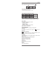
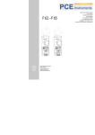
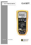
Pince Multimètre - Courants de fuites Leakage Clamp-on Meter Multimeter und Fehlerstrom-Messzange Pinza Multimetro - Correnti di fuga Pinza Multímetro - Corrientes de fugas F 62 – F 65 FRANÇAIS ENGLISH DEUTSCH ITALIANO ESPANOL 1 Notice de Fonctionnement User’s manual Bedienungsanleitung Libretto d’Istruzioni Manual de Instrucciones F 62 – F 65 English TABLE OF CONTENTS 1. GENERAL INSTRUCTIONS ..........................19 1.1. Precautions and safety measures ...............19 1.1.1. Before use.................................................19 1.1.2. While in use..............................................20 1.1.3. Symbols ....................................................20 1.1.4. Instructions ...............................................20 1.1.5. Maintenance .............................................20 1.2. Warranty ......................................................21 1.3. Maintenance ................................................21 1.4. Unpacking - Repacking................................21 2. DESCRIPTION OF THE INSTRUMENT ........22 2.1. Description of the front and rear panels ...... 22 2.2. Description of the display unit......................23 3. GENERAL DESCRIPTION .............................24 3.1. Preparation for use ......................................24 3.1.1. Power supply ............................................24 3.1.2. Installation and replacement of the batteries ....................................................24 3.2. Automatic ranges.........................................24 3.3. MAXIMUM value (MAX)................................24 3.4. Hold mode (HOLD)......................................25 3.5. Relative values (ZERO) ...............................25 3.6. 50-60Hz filter ...............................................25 3.7. Automatic shut-off (instrument) ...................25 3.8. Backlighting .................................................25 4. FUNCTIONAL DESCRIPTION .......................26 4.1. Alternating current measurement (A range) 26 4.2. Leakage current measurement (mA range) 27 4.3. AC and DC voltage measurements .............28 4.4. Resistance measurement............................28 4.5. Audible continuity test..................................29 4.6. Frequency measurement (Hz).....................30 5. SPECIFICATIONS ..........................................31 5.1. General ........................................................31 5.2. Characteristics.............................................31 5.2.1. AC current (automatic ranges) .................31 5.2.2. mAC current (automatic ranges) ..............31 5.2.3. AC voltage (automatic ranges) .................31 5.2.4. DC voltage (automatic ranges).................31 5.2.5. Resistance (Ω) and continuity ..................32 5.2.6. Frequency (automatic ranges)..................32 5.2.7. Safety........................................................32 5.2.8. General information..................................32 5.3. Environment.................................................33 5.3.1. Temperature .............................................33 5.3.2. EMC ..........................................................33 5.4. To order .......................................................33 18 F 62 – F 65 English 1. GENERAL INSTRUCTIONS 1.1. Precautions and safety measures 1.1.1. Before use You have just bought a clamp-on leakage meter. Thank you for your confidence. This clamp-on meter complies with the IEC 61010 safety standard for electronic measuring instruments. For your own safety, and that of the instrument, it is best to follow the instructions given in this manual. ∗ This instrument can be used for measurements on circuits in installation category III, in a pollution level 2 environment, with voltages not exceeding 300V with respect to ground. Definitions of the installation categories: CAT II: Measurement category II is for measurements performed on circuits directly connected to the low voltage installation. Examples: measurements on household appliances and portable tools. CAT III: Measurement category III is for measurement performed in the building installation. Examples: distribution boards, circuit-breakers, machine or industrial equipment with permanent connection to the fixed installation. CAT IV: Measurement category IV is for measurements performed at the source of the low-voltage installation. Examples: meters and measurements on primary overcurrent protection devices and ripple control units. For your safety, use only cords complying with the IEC 61010 standard. Before each use, check that they are in perfect working condition. 19 F 62 – F 65 English 1.1.2.While in use • Never exceed the maximum safe values indicated in the specifications for each type of measurement. • When the clamp-on meter is connected to the measuring circuits, do not touch any unused terminal. • Before changing functions, disconnect the measuring cords from the circuit being measured. • Never perform resistance measurements on a live circuit. 1.1.3. Symbols Refer to theàoperating Se reporter la notice manual de fonctionnement Risk of electric shock Risque de choc électrique Double insulation Isolation double 1.1.4. Instructions - Before opening the instrument, you must disconnect it from the measuring circuits and check that you are not charged with static electricity, which could destroy internal components. - A "qualified person" is someone familiar with the installation, construction, use, and hazards. He/she is authorized to start up and shut down the installation and equipment, in conformity with the safety rules. 1.1.5. Maintenance Clean the instrument with a damp cloth and soap. Do not use abrasive substances or solvents. 20 F 62 – F 65 English 1.2. Warranty This equipment is warranted against defects in materials and workmanship, in conformity with the general conditions of sale. During the warranty period, the instrument may be repaired only by the maker, who shall be free to decide whether to repair or to replace all or part of the instrument. If the equipment is returned to the maker, the cost of transport to the maker's is borne by the customer. The warranty does not cover the following cases: 1. improper use of the hardware or use in association with incompatible equipment; 2. modification of the equipment without the explicit authorization of the maker's technical staff; 3. work done by a person not approved by the maker; 4. adaptation to a particular application not anticipated in the definition of the equipment or in the operating instructions; 1. impact, fall, or flood. The contents of this manual may not be reproduced in any form without our permission. Note: warranty does not cover the magnetic head gap. 1.3. Maintenance For checking and calibration, contact one of our accredited metrology laboratories (information and contact details available on request), at our Chauvin Arnoux subsidiary or the branch in your country. 1.4. Unpacking - Repacking All of the equipment has been checked mechanically and electrically before shipping. Every precaution has been taken to ensure that the instrument reaches you undamaged. It is wise to check it promptly in order to detect any deterioration that may have occurred during transport. If any deterioration is found, state your reservations to the carrier. Attention! For reshipment, it is best to use the original packaging and state the reasons for returning the equipment as clearly as possible in a note enclosed with it. 21 F 62 – F 65 English 2. DESCRIPTION OF THE INSTRUMENT 2.1. Description of the front and rear panels 1 2 3 4 5 6 7 8 9 10 11 12 22 Jaws Protective guard Trigger MAX function Backlighting function Display unit COM input terminals HOLD function / 50-60Hz filter Switch Display reset (zero) key + Input terminals Battery well F 62 – F 65 English 2.2. Description of the display unit 50/60Hz Batteries low AUTO Automatic range MAX Maximum value display HOLD Hold mode display ZERO Relative Measurement displayed Continuity measurement V Voltage measurement A Current measurement …Hz Frequency measurement 50-60 Hz Fundamental filter active WIDE Measurement over whole pass band Automatic shut-off activated Alternating current / voltage 23 F 62 – F 65 English 3. GENERAL DESCRIPTION 3.1. Preparation for use 3.1.1.Power supply Batteries: AAA or LR03, 1.5 V (two) Battery life: 45 hours (alkaline batteries). 3.1.2.Installation and replacement of the batteries 1. is displayed when the voltage delivered by the batteries is below the operating voltage. 2. Before replacing the batteries, set the switch to "OFF", disconnect the measuring cords, and disconnect the clamp from the circuit being measured. 3. Loosen the screw and open the cover of the battery compartment with a screwdriver. 4. Replace the used batteries with two new 1.5V LR03 batteries. 5. Put the cover back in place and tighten the attachment screw. 3.2. Automatic ranges Range selection is automatic for all functions. The AUTO symbol on the display indicates this operating mode. 3.3. MAXIMUM value (MAX) In the AC current and AC&DC voltage measurement modes, the largest value can be measured simply by pressing the "MAX" button. The MAX symbol then appears on the screen. The acquisition time is 100ms. To deactivate this function, press the "MAX" button again. 24 F 62 – F 65 English 3.4. Hold mode (HOLD) The value displayed can be frozen simply by pressing the "HOLD" button. The "HOLD" symbol is then displayed on the screen. To deactivate this function, press the "HOLD" button again. 3.5. Relative values (ZERO) It is possible to compare two values, in any function except frequency measurement, simply by pressing the "ZERO" button. When the first value is displayed on the screen, press the ZERO buttons. The ZERO symbol then appears on the screen and the display unit indicates the value zero. Make your second measurement. The display unit then indicates the difference between the second value and the first value. To deactivate this function, press the "ZERO" button again. This function can be used to compare two voltage measurements (e.g. to determine a voltage drop) or to correct for the resistance of the cords when making a resistance measurement. 3.6. 50-60Hz filter It is possible to filter the signal (when making a current measurement), in order to display only the fundamental, by a long press on the "HOLD" button. The 50/60Hz symbol then appears on the screen. To deactivate this function and return to measuring over the whole passband of the instrument, effect another long press on the "50-60Hz" button. The WIDE symbol then appears on the screen. 3.7. Automatic shut-off (instrument) The clamp is shut off automatically after 10 minutes if no operation is performed. The symbol indicates that the automatic shut-off mode is activated. To deactivate automatic shut-off, hold the "ZERO" button down and operate the switch. The symbol disappears from the display unit, indicating that automatic shut-off is deactivated. 3.8. Backlighting Pressing the key activates backlighting of the display. The backlighting can be switched off manually by pressing the key; otherwise, it is switched off automatically after 180 seconds. 25 F 62 – F 65 English 4. FUNCTIONAL DESCRIPTION 4.1. Alternating current measurement (A range) 60 T II CA 50 F OF 0A V LD HO 0 I 1 c Se s 2 Hz es Pr / 60 0V A A m V AK PE Hz RO ZE 60 0V Set the switch to A~. Open the clamp by pressing the trigger. Place the clamp around the conductor to be measured and release the trigger; check that the clamp is properly closed. Read the measurement on the display unit. Note: As a safety measure, disconnect the measuring cords from the clamp before performing this operation. The clamp must be placed around a single conductor of a circuit, since otherwise the measurement may be thrown off. The measurement is optimal with the conductor centred in the middle of the jaws. 26 F 62 – F 65 English 4.2. Leakage current measurement (mA range) Load 600V CAT III 100A Press 2 Sec 50 / 60Hz HOLD OFF A mA V V Hz PEAK ZERO 600V Note: As a safety measure, disconnect the measuring cords from the clamp before performing this operation. The measurement is optimal with the conductor centred in the middle of the jaws. Set the switch to mA~. Open the clamp by pressing the trigger. Place the clamp around the active conductors (Phase conductors and Neutral) and release the trigger; check that the clamp is properly closed. Read the measurement on the display unit. The reading can be filtered to reflect only the fundamental by a long press on the HOLD key, giving an indication of the impact of the harmonics. 27 F 62 – F 65 English 4.3. AC and DC voltage measurements Set the switch to V~ for an AC voltage measurement and to V= for a DC voltage measurement. 600V CAT III 100A Press 2 Sec 50 / 60Hz HOLD OFF A mA V V Hz PEAK 600V ZERO Connect the red test cord to the "+" input terminal and the black test cord to the "COM" input terminal. Then place the probe tips in contact with the points where the AC voltage is to be measured. Read the result on the display unit. 4.4. Resistance measurement Set the switch to Ω. Connect the red test cord to the "+" input terminal and the black test cord to the "COM" input terminal. Place the probe tips in contact with the points to be measured and read the result on the display unit. 600V CAT III 100A Press 2 Sec 50 / 60Hz HOLD OFF A mA V Hz PEAK 600V 28 ZERO Note: Before making a measurement on a circuit, check that it is Off and that ANY capacitors are discharged. F 62 – F 65 English 4.5. Audible continuity test . Set the switch to Connect the red test cord to the "+" terminal and the black test cord to the "COM" terminal. Place the probe tips in contact with the circuit to be tested. If the resistance is less than 35 Ω, the buzzer will sound continuously. 600V CAT III 100A Press 2 Sec 600V CAT III 100A Press 2 Sec 50 / 60Hz HOLD 50 / 60Hz HOLD OFF OFF A A mA mA V V Hz PEAK 600V 29 Hz ZERO PEAK ZERO 600V F 62 – F 65 English 4.6. Frequency measurement (Hz) Set the switch to Hz for a frequency measurement in AC voltage mode. Connect the red test cord to the "+" input terminal and the black test cord to the "COM" input terminal. 600V CAT III 100A Press 2 Sec 50 / 60Hz HOLD OFF A mA V Hz PEAK ZERO Then place the probe tips in contact with the points where the AC voltage is to be measured. 600V Read the result on the display unit. Disconnect the probe tip cords from the clamp-on meter. 600V CAT III 100A Set the switch to Hz for a frequency measurement in AC current mode. Press 2 Sec 50 / 60Hz HOLD OFF Open the clamp by pressing the trigger. A mA V Hz PEAK 600V ZERO Place the clamp around the active conductors (Phase conductors and Neutral) and release the trigger; check that the clamp is properly closed. Read the measurement result on the display unit. Note: The frequency measurement cannot be made if the clamp-on meter detects both a current measurement and a voltage measurement. 30 F 62 – F 65 English 5. SPECIFICATIONS 5.1. General Only values with tolerances or stated limits are guaranteed. Values without tolerances are stated for information only. 5.2. Characteristics The precision is ± [% of reading (L) + number of representation units (digits or D)] under the reference conditions (see Appendix). 5.2.1. AC current (automatic ranges) Ranges 10A Resolution 1mA 80A 10mA Accuracy 1.2%±5cts(50~60Hz) 2.5%±5cts(60~500Hz) F 65 : 3.5%±10cts (500~3kHz) 5%±5 cts (50~60Hz) 80~100A 10mA Overload protection: 150 Arms F65: RMS measurement (Rooth Mean Square value) 5.2.2.mAC current (automatic ranges) Ranges 60mA Resolution 10µA 600mA 100µA Accuracy 1.2%±5cts(50~60Hz) 2.5%±5cts(60~500Hz) F 65 : 3.5%±10cts (500~3kHz) Overload protection: 150 Arms F65: RMS measurement (Rooth Mean Square value) 5.2.3.AC voltage (automatic ranges) Ranges Resolution 600V 0.1V Accuracy 1.0%±5cts (50~60Hz) 1.2%±5cts (60~500Hz) F 65 : 2.5%±5cts (500~3kHz) Input impedance: 1 MΩ Overload protection: 660 Vrms F65: RMS measurement (Rooth Mean Square value) 5.2.4.DC voltage (automatic ranges) Ranges Resolution Accuracy 600V 0.1V 1.0%±2cts Input impedance: 1 MΩ Overload protection: 660 Vrms F65: RMS measurement (Rooth Mean Square value) 31 F 62 – F 65 English 5.2.5. Resistance (Ω) and continuity Range 1kȍ Resolution Accuracy ȍ 1%+3 Max. voltage: 3.3V DC during the measurement. Overload protection: 660 Vrms Continuity selection threshold: R < 35 Ω 5.2.6.Frequency (automatic ranges) Function A-Hz A-Hz V-Hz V-Hz Ranges 0~100 Hz 100~1 kHz 0~100 Hz 100~1 kHz Resolution 0.1Hz 1Hz 0.1Hz 1Hz Accuracy 0.5%±2cts 0.5%±2cts Frequency measurement for currents greater than 10 mA RMS. Frequency measurement for voltages greater than 5 V RMS. 5.2.7.Safety IEC 61010-1 and IEC 61010-2-032: - Insulation: class III - Pollution level: 2 - Altitude < 2000 m - Installation category: CAT III 300V 5.2.8. General information Digital display unit 4 LCD digits with max. reading of 9,999 points Overload If a reading overshoots the range, the symbol is displayed. Battery Low indicator is displayed when the voltage delivered by the battery is less than the operating voltage. Sampling 2 measurements/s for the digital display, 100ms for the MAX function. Degree of protection of the enclosure IP 30 as per NF EN 60529 Maximum opening of jaws ∅ 28 mm Dimensions (L x l x H): 218 x 64 x 30 mm Weight 280 g (with batteries) 32 F 62 – F 65 English 5.3. Environment 5.3.1. Temperature Operation: 0°C to 40°C, < 80 % RH Storage: -10°C to 60°C, < 70 % RH 5.3.2. EMC Immunity and Emissions as per EN 61326-1 5.4. To order F62 P01120760 F65 P01120761 Instrument delivered in a box with: 1 operating manual 1 set of measuring cords (D4mm, one black and one red) 2 1.5V AAA or LR3 batteries 1 carrying bag Accessories and spare parts Set of 2 silicon leads with D4mm plugs Set of 2 alligator clamps 2P+E socket tester Carrying case 200x100x40 mm P01295454Z P01295453Z P01295457Z P01101997Z P01298065Z APPENDIX: Reference conditions Sine-wave signal: - Frequency from 48 to 65Hz - No DC component Temperature 23°C ± 5°C, RH < 80% External magnetic field < 40 A/m No alternating magnetic field Conductor being measured centred (in A) Specifications given for values from 5 to 100% of each range. Note: For a crest factor CF between 1.4 and 3 at full scale, add 1% to these specifications. 33 F 62 – F 65 07 - 2014 Code 691435A00 – Ed. 6 DEUTSCHLAND - Chauvin Arnoux GmbH SCHWEIZ - Chauvin Arnoux AG Straßburger Str. 34 - 77694 Kehl / Rhein Moosacherstrasse 15 – 8804 AU / ZH Tel: (07851) 99 26-0 - Fax: (07851) 99 26-60 Tel: 044 727 75 55 - Fax: 044 727 75 56 ESPAÑA - Chauvin Arnoux Ibérica S.A. UNITED KINGDOM - Chauvin Arnoux Ltd C/ Roger de Flor N° 293, Planta 1 Unit 1NelsonCt, FlagshipSq–ShawCross Business Park 08025 Barcelona Dewsbury –West Yorkshire–WF127TH Tel: 902 20 22 26 - Fax: 934 59 14 43 Tel: 01924 460 494 - Fax: 01924 455 328 ITALIA - Amra SpA MIDDLE EAST - Chauvin Arnoux Middle East Via Sant’Ambrogio, 23 P.O. BOX 60-154 - 1241 2020 JAL EL DIB (Beirut) - 20050 Bareggia di Macherio (MB) LEBANON Tel: 039 245 75 45 - Fax: 039 481 561 Tel: (01) 89 04 25 - Fax: (01) 89 04 24 ÖSTERREICH - Chauvin Arnoux Ges.m.b.H CHINA-Shanghai Pu-Jiang-EnerdisInstrumentsCo. Ltd Slamastrasse 29/2/4 - 1230 Wien 3F,3rdBuilding-N°381XiangDeRoad-200081SHANGHAI Tel: 01 61 61 961-0 - Fax: 01 61 61 961-61 Tel: +86 21 65 21 51 96 - Fax: +86 21 65 21 61 07 SCANDINAVIA - CA Mätsystem AB USA - Chauvin Arnoux Inc - d.b.a AEMC Instruments Box 4501 - SE 18304 TÄBY 200 Foxborough Blvd. - Foxborough - MA 02035 Tel: +46 8 50 52 68 00 - Fax: +46 8 50 52 68 10 Tel: (508) 698-2115 - Fax: (508) 698-2118 http://www.chauvin-arnoux.com 190, rue Championnet - 75876 PARIS Cedex 18 - FRANCE Tél. : +33 1 44 85 44 85 - Fax : +33 1 46 27 73 89 - [email protected] Export : Tél. : +33 1 44 85 44 86 - Fax : +33 1 46 27 95 59 - [email protected]