1
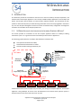
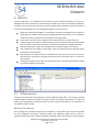
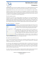
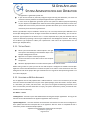
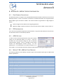
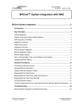
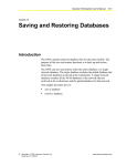
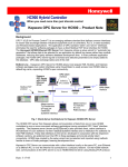
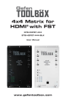
S4 OPEN APPLIANCE
USER MANUAL
AND
INSTALLATION GUIDE
S4 OPEN APPLIANCE
TABLE OF CONTENTS
1.
Introduction ......................................................................................................5
S4 Open Appliance relationship with Johnson Controls Metasys®..........................5
Verifying the Integrity of the N2 Bus ....................................................................6
Physical Specifications .........................................................................................6
1.1.
1.2.
1.3.
2.
Concepts............................................................................................................7
2.1.
S4 Open Appliance ..............................................................................................7
N2 Device Type Templates ....................................................................................................... 7
Auto Configure Wizard ............................................................................................................. 8
2.2.
2.3.
Building Control Network ....................................................................................8
Physical Networks ...............................................................................................9
Upstream Network ................................................................................................................... 9
Open Upstream Interfaces ..................................................................................................... 10
Network 1, Network 2, …, Network n .................................................................................... 10
Network Extended N2 Connections ....................................................................................... 10
Com Port Assignments ........................................................................................................... 11
2.4.
3.
S4 Open: Management Console ......................................................................... 11
System Administration and Operation ............................................................. 12
3.1.
3.2.
3.3.
3.4.
3.5.
3.6.
3.7.
3.8.
3.9.
3.10.
3.11.
3.12.
3.13.
4.
Automatic Windows Security and Port Configuration ......................................... 12
Auto Detecting S4 Open Appliances ................................................................... 12
Manually Linking to S4 Open Appliances ............................................................ 12
Setting System Options ..................................................................................... 13
System Status ................................................................................................... 13
Remote System Reboot ..................................................................................... 13
Enabling or Disabling Physical Networks ............................................................ 13
Auto Configure .................................................................................................. 14
N2 Device Properties ......................................................................................... 14
N2 Point Assignments........................................................................................ 14
Testing Points ................................................................................................... 15
Updating an S4 Open Appliance ......................................................................... 15
Updating The Management Console .................................................................. 16
IT Security and Network Administration Considerations ................................... 17
4.1.
4.2.
4.3.
4.4.
4.5.
S4 Open: Management Console Installation ....................................................... 17
Automated Error Reporting ............................................................................... 17
TCP / IP Port Requirements and Firewall Settings ............................................... 17
Windows CE Remote Management Tool ............................................................ 17
IP Address Configuration ................................................................................... 17
Software Services and System Solutions for the Enterprise
http://www.theS4group.com
Page 3 of 21
S4 OPEN APPLIANCE
TABLE OF CONTENTS
Configuring a static IP address without a DHCP or BOOTP server ......................................... 17
4.6.
5.
Windows Domain or Workgroup Membership ................................................... 18
Appendix A – OPC Specific Information ............................................................ 19
5.1.
5.2.
6.
Point Naming Conventions ................................................................................ 19
Addressing the OPC-N2 Router .......................................................................... 19
Appendix B – BACnet Specific Information ........................................................ 20
6.1.
6.2.
6.3.
6.4.
7.
Point Naming Conventions ................................................................................ 20
PICS Information ............................................................................................... 20
APDU Settings ................................................................................................... 20
Metasys® N2 to BACnet Point Mapping.............................................................. 20
Appendix C – An Overview of the Metasys® N2 Bus .......................................... 21
7.1.
7.2.
7.3.
Physical Specifications of the N2 Bus ................................................................. 21
Operating Specifications .................................................................................... 21
N2 Protocol Information .................................................................................... 21
Software Services and System Solutions for the Enterprise
http://www.theS4group.com
Page 4 of 21
S4 OPEN APPLIANCE
INTRODUCTION
1. INTRODUCTION
This document provides an orientation for the new user to the user interface, concepts of operation, and
administration of all S4 Open Appliances. The currently available S4 Open Appliances are the S4 Open: N2
Switch, the S4 Open: OPC-N2 Router, and the S4 Open: BACnet-N2 Router. The functionality of each
product is determined by factory installed licensing certificates and can be easily upgraded in the field at
any time. The S4 Open: Management Console is used for the administration, configuration and diagnostic
evaluation of all members of the S4 Open product line.
1.1. S4 OPEN APPLIANCE RELATIONSHIP WITH JOHNSON CONTROLS METASYS®
®
This section provides an orientation of how the S4 Open Appliance relates to a Metasys building
automation system. For a general overview of the Metasys® N2 Bus refer to Appendix C.
The following graphic illustrates an S4 Open: OPC-N2 Router installation with:
One Upstream N2 Network on COM4,
One Downstream N2 Network on COM1
One OPC interface utilizing the Ethernet port
OPC Based HMI
Iconics Genesis32
Acuity
A-Studio
Reliable Controls
WonderWare
Etc...
OPTIONAL
Metasys®
Workstation
Ethernet Network
OPC Protocol
(Ethernet)
Metasys®
Supervisory Controller
S4 Open
Appliance
N2 Protocol
(RS-485)
VMA Device
(N2B
Protocol)
DX-9100
(System 91
Protocol)
TEC2145-2
(N2 Open
Protocol)
MS-MIG3120
(Metasys
Integrator)
TCS Basys
(VND Device)
All N2 communications from the supervisory controller pass through the S4 Open Appliance. The S4 Open
Appliance is the gatekeeper for access to the N2 field devices and controls which upstream system is
allowed to become the master of the N2 bus at any time.
Software Services and System Solutions for the Enterprise
http://www.theS4group.com
Page 5 of 21
S4 OPEN APPLIANCE
INTRODUCTION
1.2. VERIFYING THE INTEGRITY OF THE N2 BUS
Before attempting to install an S4 Open Appliance it is strongly recommended that the integrity of the N2
Bus be verified. A standard digital volt meter may be used but we recommend using a B&B Electronics
ComBus Quick Tester. The ComBus Quick Tester quickly tests the entire N2 bus. It checks bus voltages
indicating Pass/Fail, counts all devices on the bus and identifies each device for display. It works as a
Master Controller to check the entire system or segments of the network. Refer to Appendix C for further
information.
1.3. PHYSICAL SPECIFICATIONS
S4 Open Appliances are hosted on an Advantech UNO-2059E industrial PC
Power supply voltage: 10-30 VDC, reversed wiring protection
Power Consumption: 0.6A max under +24V power input or 1.2A max. under +12V power input
Power Requirement: 1A typical under +24 V power input or 1.5 A typical under +12 V power input
Operating temperature: 0 ~ 55°F (0 ~ 131°F)
Chassis size: 164.8 mm (W) x 106.5 mm (L) x 35.5 mm (H) (6.5" x 4.2" x1.4")
Weight: 0.8 kg
Software Services and System Solutions for the Enterprise
http://www.theS4group.com
Page 6 of 21
S4 OPEN APPLIANCE
CONCEPTS
2. CONCEPTS
S4 Open Appliances are implemented using advanced object oriented technology. This gives our
developers the power to perform the tasks necessary to deliver the services you need. More importantly,
it enables us to manage all of the proprietary details of physical devices behind the scenes and present a
consistent and predictable view of your building automation environment to you.
Objects will dynamically be added or removed from the left hand navigation pane as folders or
detail objects as needed to represent your building automation environment. You can expand or
minimize the amount of detail that is presented in the navigation pane.
Details about each object in the navigation pane will be presented in the right hand pane.
Properties pages are available as right click options from many objects. Wizards and drill down
links provide more details about the objects and allow you to adjust user settable parameters.
Real Time performance statistics are available from the properties page of many objects.
Color coded icons are included in many places to give you quick look status information about
the objects that they represent.
Most operations are intuitive but help is available at any time you need it. You can use the main
Help menu item, right click on any object and select help in the drop down menu, or press F1 on
your keyboard.
Configuration changes can be made on an operational system and will automatically be reflected
in the data provided on all interfaces.
2.1. S4 OPEN APPLIANCE
All system level commands are issued from the S4 Open Appliance object folder or set through associated
properties pages. In the above example the specific product is the S4 Open: OPC-N2 Router, so that is the
default name displayed for the appliance object. This name may be customized for your installation on
the appliance properties page.
N2 DEVICE TYPE TEMPLATES
Point mappings are provided as N2 Device Type Templates. A unique Device Type Template is provided
®
for each combination of Metasys hardware platform and application loaded into the Unitary or
Application Specific Controller. Vendor provided N2 Compatible devices also have Device Type Templates.
Software Services and System Solutions for the Enterprise
http://www.theS4group.com
Page 7 of 21
S4 OPEN APPLIANCE
CONCEPTS
Device Type Templates are automatically assigned to each device object by the Auto Configure wizard.
You have the option to override the assigned Device Type Template with your own variation for custom
applications.
A default set of N2 Device Type Templates are loaded when the S4 Open Appliance is delivered to you.
Additional Device Type Templates may be loaded via a library provided with the S4 Open: Management
Console from a properties page on the S4 Open Appliance main folder, or you may develop your own for
unique requirements. Periodically check The S4 Group web site for updated or new Device Type
Templates that may be downloaded and installed into your S4 Open Appliance at no charge.
AUTO CONFIGURE WIZARD
The primary system level configuration wizard is initiated as a right click command option on the S4 Open
Appliance folder. In most cases initiating this command is all you need to do to fully configure and
commission a S4 Open Appliance after loading the appropriate set of N2 Device Type Templates into the
appliance.
2.2. BUILDING CONTROL NETWORK
The virtual objects in the Building Control Network (BCN) provide a unified view of your building
automation environment. All devices and their points found on the downstream physical networks are
represented as objects under this folder. Most of your interaction with the system will be with objects
contained in this folder.
N2 address translation is automatically performed as multiple legacy downstream N2 networks are
merged into the BCN during the Auto Configure process, ensuring that N2 addresses published to the
Upstream N2 network will be unique. This allows you to merge multiple legacy N2 networks into one
virtual N2 network without having to physically touch any of the N2 devices to adjust addresses. The
properties page for a device object shows the N2 address that it will publish on the Upstream N2 network.
This is a user configurable value. You can also see the physical network and physical N2 address where the
device was found on a legacy N2 network.
Important Note - There is no data routing between the upstream interfaces and the physical N2
networks until the Auto Configure process is completed. Even though points exist on the devices on the
physical N2 networks they are not accessible via any upstream interface until this process is completed.
The Auto Configure Process:
Scans all physical networks
Creates all of the virtual objects in the BCN
Assigns N2 Device Type Templates to device objects,
Creates the appropriate routing algorithms for all published objects, and
Publishes the point objects to the default upstream interfaces.
Software Services and System Solutions for the Enterprise
http://www.theS4group.com
Page 8 of 21
S4 OPEN APPLIANCE
CONCEPTS
The virtual devices and points contained in the BCN folder can be published to any licensed upstream
interface. You have the option of overriding the default publishing configuration on the properties page of
any point object.
By default:
All current S4 Open Appliances publish all point and device objects to the Upstream N2 interface.
The S4 Open: OPC-N2 Router, in addition, publishes all device and point objects to the industry
standard open OPC interface with the addition of “Release” points witch OPC does not natively
support.
The S4 Open: BACnet-N2 Router, in addition, publishes all device and point objects to the
industry standard open BACnet interface.
You can manually create purely virtual device objects and point objects in the BCN. That is, objects that
have no linkage to a physical device. These objects are used by our optional controller packages to store
the results of calculations or publish global variables.
The “online” status of a N2 device is denoted by the color of the associated device object icon. If access to
a device fails the N2 router will try multiple times to re-initialize the N2 device and try the N2 command
again. This is completely separate and independent from the online / offline status of a device in a
®
Metasys supervisory controller, Operator Workstation, or M-Series Workstation.
2.3. PHYSICAL NETWORKS
Folders and objects within the container represent communications interfaces to the S4 Open Appliance.
Within the properties page for each network object the following options are available:
Associate a physical COM port with the network
Associate an Ethernet Serial Server with the network (this feature has not been implemented
yet)
Monitor real time performance of the network
Examine the properties of devices found on the legacy N2 network
Search for Field Devices on the network
Enable or Disable the network
Most of your interaction with objects within the Physical Networks folder will be during initial setup of the
S4 Open Appliance or when using the S4 Open Appliance as a diagnostic tool for your legacy N2 networks.
UPSTREAM NETWORK
A network object for the upstream N2 interface used to publish device and point objects resides under
the Physical Networks folder. By default, this is configured for COM4.
®
Connecting a Metasys supervisory controller to the Upstream N2 port is completely optional (except
®
when using the S4 Open: N2 Switch). If there is no Metasys supervisory controller attached the S4 Open
Software Services and System Solutions for the Enterprise
http://www.theS4group.com
Page 9 of 21
S4 OPEN APPLIANCE
CONCEPTS
Appliance will assume the role of the N2 Master automatically. You can disable the Upstream N2 network
®
from its property page if you want to shut off communications to the Metasys supervisory controller.
®
Important Note -We always caution customers about the risks of keeping both their legacy Metasys
supervisory controller and their new head end in the configuration. Doing this is technically viable but
both head end systems may try to control the value of a point on a N2 device at the same time. You need
to understand the control algorithms and programming implemented in both head end systems and make
sure there are no conflicting control actions being generated.
OPEN UPSTREAM INTERFACES
Depending on the model of your S4 Open Appliance it will support one or more of the following open
protocols / interfaces as a target for publishing Device and Point objects to. OPC, BACnet / IP, XML, and
SNMP utilize the system’s Ethernet port and therefore these options will not have a network object in the
Physical Networks folder. Others, like BACnet MS/TP do require a physical interface. In these cases you
will see additional network objects in the form of additional folders under the Physical Networks folder.
NETWORK 1, NETWORK 2, …, NETWORK N
Network n is a view of what the S4 Open Appliance has found on each of
the Downstream legacy BAS networks or field buses. “N” refers to the
network number. The network type is found in the properties page for
®
the network. In this case we are working with Metasys N2 networks.
Important Note -The Search Field Devices command available from a
right click on the Network device object folders should be used only
when manually configuring the system or using the console as an N2
network diagnostic tool. Search Field Devices creates device objects in
the corresponding Network n folder but does not fully configure the
system. Under normal circumstances the Configure Wizard at the router
node level will handle the complete process of setting up the system.
NETWORK EXTENDED N2 CONNECTIONS
If you need more Downstream N2 interfaces than are physically provided by the COM ports on the
appliance, or you need to extend N2 connections over your Ethernet infrastructure, commercially
available Ethernet Serial Servers may be utilized.
The serial server is fully integrated with the network object interface. You will select a serial server type
and its IP address via the properties page for the Downstream or Upstream interface. Utilizing this
technology you can add as many Downstream networks as you need to license for an installation (within
reason), however you can have only 1 Upstream N2 network. Contact your reseller if you need to
purchase licenses for additional interfaces.
The initial release of the S4 Open Appliances supports Advantech, B&B and Sealevel Systems Ethernet
serial servers. Check the S4 Group web site for an updated list of tested and supported devices.
Software Services and System Solutions for the Enterprise
http://www.theS4group.com
Page 10 of 21
S4 OPEN APPLIANCE
CONCEPTS
Important Note: The S4 Open Appliances provide a lot of flexibility when integrating legacy N2
networks. Please be aware that you must still follow all of the address space limitations and honor the
®
Metasys reserved N2 addresses when publishing to the Upstream N2 network. Typically, this means that
®
you can assign N2 addresses 1 through 253. Addresses 0, 254, and 255 are reserved for Metasys .
COM PORT ASSIGNMENTS
Physical COM ports are labeled on the S4 Open Appliance case. The default assignment of the UNO 2059
serial ports by an S4 Open Appliance is:
COM4 – Upstream N2 Network
COM1 – Downstream N2 Network 1
COM2 – Downstream N2 Network 2
COM3 – Downstream N2 Network 3
The assignments of N2 networks may be changed as required by your project through the S4 Open:
®
Management Console. All COM ports have been factory configured to be compatible with your Metasys
N2 bus.
2.4. S4 OPEN: MANAGEMENT CONSOLE
All user interaction with the system is done through the S4 Open: Management Console. The console will
enable you to manage all S4 Open Appliances in your enterprise. Launch the console from the Windows
Start menu. The S4 Open: Management Console is compatible with all versions of Microsoft Windows
from XP on. The console may be installed on as many machines as you need at no additional charge.
Important Note: You will need to manually uninstall any previous versions of the console prior to
installation through the Add/Remove Programs utility in Windows Control Panel.
Software Services and System Solutions for the Enterprise
http://www.theS4group.com
Page 11 of 21
S4 OPEN APPLIANCE
SYSTEM ADMINISTRATION AND OPERATION
3. SYSTEM ADMINISTRATION AND OPERATION
This section provides a sample of the most used features and services of the S4 Open Appliances. It is
intended as a general overview to continue your orientation to the system and not as a complete user’s
manual. The system has many more features and capabilities than described here. Refer to the on-board
Help system for complete details.
3.1. AUTOMATIC WINDOWS SECURITY AND PORT CONFIGURATION
Upon startup the S4 Open: Management Console automatically verifies that the host it is running on has
its ports and firewall configured properly for communications with any S4 Open Appliance. It will prompt
you for permission to change any settings that need to be adjusted for proper operation. The S4 Open:
rd
Management Console will also make any adjustments necessary for 3 party client programs running on
the same host to successfully communicate with the S4 Open Appliance
3.2. AUTO DETECTING S4 OPEN APPLIANCES
The S4 Open: Management Console starts in Auto Detect mode by default. Any S4 Open Appliance in the
same local network segment will automatically identify itself to the console and be identified by an S4
Open Appliance object represented by a new folder in the console navigation pane. The status of the Auto
Detect service is indicated in the lower right hand corner of the window any time that the “Console” node
is selected in the left hand pane.
Notice that the magnifying glass icon is selected in the menu bar. You can use this button to put the
system into Auto Detect mode or to do a scan of a specified range of IP addresses for S4 Open Appliances.
Important Note - In this initial release on the S4 Open: Management Console you see a periodic
snapshot of status information from the S4 Open Appliances. Occasionally, you may need to use the F5
key (Refresh Screen) to get the most recent status of an appliance or object configured in an appliance.
Please try this before assuming that the information you see is incorrect.
3.3. MANUALLY LINKING TO S4 OPEN APPLIANCES
To manually add appliances that are not Auto Detected, right click on S4 Open: Management Console and
select New -> Link to S4 Appliance. Add the appliance to the console by IP address. Refer to Help for
detailed instructions on the Auto Detection Service for your S4 Open Appliance.
Software Services and System Solutions for the Enterprise
http://www.theS4group.com
Page 12 of 21
S4 OPEN APPLIANCE
SYSTEM ADMINISTRATION AND OPERATION
Alternatively, you can click on the S4* icon on the menu bar to manually set up a link to a S4 Open
Appliance
The process is completed by specifying the IP address of the desired S4 Open Appliance in the following
window.
3.4. SETTING SYSTEM OPTIONS
The Date, Time, and Time Zone can be configured from the General tab on the Appliance Properties page.
To get to the properties page right click on the S4 Open Appliance folder in the navigation page and select
Properties.
3.5. SYSTEM STATUS
The S4 Open Appliance is normally in “Running” mode when the Properties/General tab is viewed. If the
system is in “Service” or anything other than “Running” mode this typically indicates either a licensing
problem or incorrect software installation on the S4 Open Appliance. In this case you will need to contact
your reseller for assistance.
3.6. REMOTE SYSTEM REBOOT
If it ever becomes necessary to reboot your S4 Open Appliance you can do this remotely using the Reboot
button on the General tab of the Properties page. You will see a change in the system status, hear a short
beep from the appliance itself, and the system will be restarted.
3.7. ENABLING OR DISABLING PHYSICAL NETWORKS
You can disable unneeded physical
networks by selecting or deselecting a
check box on the network properties page.
When you disable a network it will be
ignored during the “Configure” process. At
run time no communications will occur
with disabled networks. You will see the
network device object icon go gray for
disabled networks. For instance, here the
Upstream Network is enabled.
Software Services and System Solutions for the Enterprise
http://www.theS4group.com
Page 13 of 21
S4 OPEN APPLIANCE
SYSTEM ADMINISTRATION AND OPERATION
3.8. AUTO CONFIGURE
Run the Auto Configure process by right clicking on the top level folder of the S4 Open Appliance and
selecting Configure.
Important Note - You can skip forward in the process using the “GoTo Next” control any time that the
system is exploring or searching downstream networks by selecting the down arrow icon to the right of
the progress bar. This feature can significantly decrease the amount of time that it takes to commission a
S4 Open Appliance if you are sure of the number of N2 devices on each legacy N2 network and the highest
address where a device will be found.
3.9. N2 DEVICE PROPERTIES
Each device object configured by the system has a
properties page where you can investigate details about the
device.
The N2 device hardware type
®
The loaded Metasys application
The N2 Device Type Template assigned. You can
manually override the assigned N2 Device Type Template by
clicking on the Change button.
The device’s actual N2 address on the physical
network
The virtual N2 address assigned to the device
®
The Metasys firmware version running in the
device
The HVAC Pro version
The device creation date
3.10. N2 POINT ASSIGNMENTS
Device Types are defined based on the hardware family and
loaded application. The point mappings were taken from
information available in vendor documentation and are
provided based on the information available. Before relying
on these mappings for mission critical activities we advise you
to take a few preliminary steps.
Prune any unneeded points from the device to
minimize the volume of traffic generated.
Look at the comments for each point and adjust the
source string to reflect the actual configuration of
the device. In some cases point addresses are
dynamically assigned to the next available I/O when
Software Services and System Solutions for the Enterprise
http://www.theS4group.com
Page 14 of 21
S4 OPEN APPLIANCE
SYSTEM ADMINISTRATION AND OPERATION
the application is generated by HVAC Pro.
If your devices include any manually configured single side loop point definitions, etc. these will
need to be manually added to the S4 Open Appliance Device Type definition.
In some cases the application generation process uses points for different purposes depending
on your response to the Q&A session while the device is being defined and loaded. In these cases
multiple alias names for the point have been provided. We advise you to remove those that are
unnecessary from the Device Type definition.
Device Type definitions may be modified in several ways. You can always edit the point definitions from
the S4 Open Management Console. Changes will take effect immediately. Alternatively, you can edit the
N2 Device Type Template for the device. This is a comma separated value (.CSV) file delivered with the
system or obtained by exporting a Device Type Template from the Management Console. After editing
the N2 Device Type Template to reflect your requirements it will need to be imported back into the
Device Type Template library.
3.11. TESTING POINTS
Select a point associated with a device object in the right
hand pane of the Building Control Network object in the
S4 Open: Management Console.
Right click on the point and select properties.
Use the Test button on the Source tab to start the point
test process.
Select the appropriate button to confirm that the point can be read or written.
Before writing a value to a point you must be sure that the point is configured as writable in the S4 Open
Appliance and that the BAS field device will allow the point to be written. Values entered into the write
dialog box must be of the proper data type and within the size range of the data point being tested or an
error will be displayed.
3.12. UPDATING AN S4 OPEN APPLIANCE
The S4 Appliance can be easily updated with a USB thumb drive. Place in the root directory of the USB
drive all of the files and folders that are part of the update package, these will include a “startup” folder,
an “automation_net” folder, and control files. The system can recognize the following commands in the
form of control files (note that these files are empty, the system maintenance process just looks for their
existence in the root directory):
File Name – Action
noS4appliance - Will start up the UNO 2059 without initiating the S4 Open applications. As long as this
file exists on the USB thumb drive the appliance application will not start up.
updateS4appliance - saves the certificate and automation.net.xml files from the current configuration.
Then updates the build and startup.bat file on the appliance. After the action is completed this file is
renamed to prevent accidental multiple updates.
Software Services and System Solutions for the Enterprise
http://www.theS4group.com
Page 15 of 21
S4 OPEN APPLIANCE
SYSTEM ADMINISTRATION AND OPERATION
initS4appliance - saves the automation.net.xml file from the current configuration onto your USB
thumb drive. This replaces the automation.net.xml on the appliance with a default configuration file. After
the action is completed this file is renamed to prevent accidental initialization of the system
configuration.
updateDNA - saves the automation.net.xml file from the current configuration. Then replaces the file on
the appliance with the one located in the \usb hard disk\dna folder. After the action is completed this file
is renamed to prevent accidental multiple updates.
updatecert - saves the automation.cert.xml file from the current configuration. Then replaces the file on
the appliance with the one located in the \usb hard disk\cert folder. After the action is completed this file
is renamed to prevent accidental multiple updates.
You can simultaneously request several maintenance actions by creating the appropriate files in the root
of the USB thumb drive.
To initiate the process simply insert the USB thumb drive into the appliance and reboot the system via the
management console, this makes sure that all configuration information is saved before the reboot.
Note: You must use a USB 1.0 compatible thumb drive.
The update and initialize process could take several minutes to complete. While the update is in process
you will not be able to access the appliance through the Management Console. You will hear a beep from
the appliance when the reboot is initiated and another beep as the N2 Router application starts its
initialization process. A log file is created in the Startup folder on the USB thumb drive indicating the
results of the update process. Verify that all file copies were successful in this log file. When the
application is fully operational you will again be able to access it through the S4 Open Management
Console. As a final step verify the version information through the Management Console using the
properties page for the appliance.
3.13. UPDATING THE MANAGEMENT CONSOLE
S4 Open Management Console updates are applied separately on your Windows PC using the provided
.msi file.
Software Services and System Solutions for the Enterprise
http://www.theS4group.com
Page 16 of 21
S4 OPEN APPLIANCE
SECURITY AND NETWORK ADMINISTRATION
4. IT SECURITY AND NETWORK ADMINISTRATION CONSIDERATIONS
Under normal circumstances you will not need to use the information in this section. It provides information about
system installation, how the system utilizes your IT environment, and security considerations. It is provided here to
assist your IT staff in supporting the S4 Open Appliances.
4.1. S4 OPEN: MANAGEMENT CONSOLE INSTALLATION
The S4 Open: Management Console is installed from a Microsoft installation package. Typically, this is named “S4
Open Management Console.msi”. Simply copy this file to each PC upon which you want to install the software and
double click on the file name. The installation process will automatically start and a wizard will guide you through
the process.
4.2. AUTOMATED ERROR REPORTING
The S4 Open Appliances and the S4 Open: Management Console are all capable of automatically sending error
reports to the development team. In order to enable this capability you must ensure that an SMTP path exists
through any routers or firewalls from the device to the Internet.
4.3. TCP / IP PORT REQUIREMENTS AND FIREWALL SETTINGS
The following ports must be open to enable full functionality of the S4 Open Appliances. The S4 Open:
Management Console properly configures these resources for the host system it is running on but there may be
occasions where your IT support staff or network administrator needs to know these details.
UDP Port 135 – DCOM / OPC Support
TCP Port 25 – Outbound SMTP support
UDP Port 61134 – Auto Detect S4 Open Devices
UDP Port 68 – BOOTP Support for the S4 Open: Management Console
UDP Port 68 – DHCP support for the S4 Open: Management Console
4.4. WINDOWS CE REMOTE MANAGEMENT TOOL
The Windows CE Remote Management Tool is available on all UNO-2059E systems and later. The remote
management tool can be accessed using a web-browser pointed to the IP Address of the S4 Open Appliance. The
default user name is Admin and the password is S4Appliance. Please note that the S4 Appliance must be powercycled for configuration changes made using the remote management tool to take effect.
4.5. IP ADDRESS CONFIGURATION
A new system installation defaults to automatic IP assignment. If the customer network contains either a BOOTP
or DHCP server it will use the MAC address of the appliance to assign either a fixed IP address or a dynamic IP
address to the S4 Open Appliance. We highly recommend that your IT department configures your BOOTP or DHCP
server to assign a fixed IP address to the S4 Open Appliance.
CONFIGURING A STATIC IP ADDRESS WITHOUT A DHCP OR BOOTP SERVER
Software Services and System Solutions for the Enterprise
http://www.theS4group.com
Page 17 of 21
S4 OPEN APPLIANCE
SECURITY AND NETWORK ADMINISTRATION
By default, the S4 Open Appliance will attempt to retrieve an IP address from a DHCP or BOOTP server. If one is
not available on the network where the S4 Open Appliance is being installed, the Appliance can be configured to
use a static IP address. Microsoft Windows includes a DHCP failover mechanism known as APIPA. With APIPA,
DHCP clients can obtain IP addresses when DHCP servers are nonfunctional or absent. APIPA exists in all popular
versions of Windows except Windows NT. To complete this procedure, it is important to follow these next steps
exactly as prescribed.
1.
2.
3.
4.
5.
6.
7.
Start with the S4 Open Appliance powered off.
Install the S4 Open Management Console on a Windows PC.
Set your PC Ethernet adapter to automatically obtain an IP address. (Refer to Windows help for additional
information on this procedure.)
Connect a crossover Ethernet cable between the S4 Open Appliance and the PC.
Power on the S4 Open Appliance.
The S4 Open Appliance will go through its normal initialization process.
The PC and the S4 Open Appliance will negotiate addresses, with Windows automatically assigning IP
addresses in the range of 169.254.x.x.
The following two steps may take several minutes, please be patient.
When the initialization process is complete and the addresses are negotiated the S4 Open Appliance will be autodetected by the Management Console and its folder will show up in the navigation pane. At this point you will
have normal communication between the Management Console and the appliance. Now, you will be able to go to
the S4 Open Appliance’s properties page, select Communications Protocols, and change the IP address to a fixed IP
address and subnet mask of your choice, the other fields can be left blank. Once this is done, select the Apply
button. The S4 Open Appliance will need to be rebooted for the changes to take effect, use the Reboot button on
the General Properties tab to initiate the reboot sequence. The S4 Open Appliance will re-initialize itself with the
address and subnet mask that was assigned to it.
To maintain communication between the Management Console and the S4 Open Appliance it is necessary to
change the IP address of the PC running the Management Console to a fixed IP address in the same subnet as the
S4 Open Appliance.
4.6. WINDOWS DOMAIN OR WORKGROUP MEMBERSHIP
The UNO 2059E chosen for the production release of the S4 Open Appliances runs a release of Windows CE.NET
that cannot fully participate as a host in a Windows domain or Workgroup environment. Any OPC client with a
built in OPC browser that is Windows aware can search for and attach to remote S4 Open: OPC-N2 Routers.
Software Services and System Solutions for the Enterprise
http://www.theS4group.com
Page 18 of 21
S4 OPEN APPLIANCE
APPENDIX A
5. APPENDIX A – OPC SPECIFIC INFORMATION
5.1. POINT NAMING CONVENTIONS
Each N2 device is assigned a folder name under the OPC Server.
enumerated under this folder.
Points for each N2 device are
5.2. ADDRESSING THE OPC-N2 ROUTER
From the Microsoft networking standpoint, our appliance looks like a standalone application server that is
outside of the Windows domain environment. This brings up several concerns that users and integrators
traditionally have with distributed OPC installations:
DCOM configuration and security.
Many developers have written their OPC clients in a way that is very dependent on Microsoft
Active Directory and domain services.
Some OPC clients support only local OPC servers or provide much better support for local OPC
servers than for remote servers.
The S4 Open Management Console eliminates all of these typical issues with remote OPC server support.
As it detects each S4 Open: OPC-N2 Router in your network, it transparently creates a local OPC Proxy
Server and establishes a tunnel to the appliance. The OPC Proxy Server, and associated tunnel, is
established on the local machine during the Auto Detection process, or manual linking process, for S4
Open Appliances. We take care of all of the details for you! From the standpoint of your OPC client
application, it is talking to a local OPC server so there are no DCOM configuration or security issues, and
you benefit from the full functionality of a local OPC server and can simply use the clients OPC browser
functionality to map points. If you’re interested in more technical details - it is actually an In-Process OPC
Server. Some OPC clients make a distinction between a local OPC Server and an in-process OPC Server. If
this is the case for your OPC client configure the interface as an in-process OPC Server.
Software Services and System Solutions for the Enterprise
http://www.theS4group.com
Page 19 of 21
S4 OPEN APPLIANCE
APPENDIX B
6. APPENDIX B – BACNET SPECIFIC INFORMATION
6.1. POINT NAMING CONVENTIONS
The BACnet-N2 Router is assigned a user selectable BACnet Network Number and Device ID and uses the
BACnet/IP protocol. Points on N2 devices connected to the BACnet-N2 Router are assigned standard
BACnet Object Types and Instance numbers. The Instance numbers are generated as 6 digit integers as
follows:
Leftmost 3 digits: The N2 address of the originating N2 device.
Rightmost 3 digits: A sequence number to ensure that the instance number is unique, starts at 1.
6.2. PICS INFORMATION
If one has not been provided along with this documentation, a copy of the PICS statement can be found in
the documents section on the S4 Group’s website.
6.3. APDU SETTINGS
In order to ensure maximum performance verify that the APDU
setting for the BACnet-N2 Router are correct. Under the
Protocols tab in the Properties dialog box, click on Advanced
Communications Settings. There it is possible to adjust APDU
Timeout and APDU-Segment Timeout settings.
For best
performance it is recommended to set both parameters to at
least 10,000. It is recommended that these settings be adjusted before running the configure wizard.
6.4. METASYS® N2 TO BACNET POINT MAPPING
The following table lists all the Metasys® N2 point types and what BACnet point types the BACnet-N2
Router maps them to.
Metasys N2 Point Type
AI (Analog Input)
BI (Binary Input)
AO (Analog Output)
BO (Binary Output)
ADF (Analog Data Float)
ADI (Analog Data Integer)
BD (Binary Data)
LRS (Logic Results)
PMK (Programmable Module Constants)
PMO (Programmable Module Outputs)
PML (Programmable Module Logic)
PMA (Programmable Module Accumulator)
Maps to BACnet Point Type
AI (System91 Points Map to AV)
BI (System91 Points Map to BV)
AO (System91 Points Map to AV)
BO (System91 Points Map to BV)
AV
AV
BV
BV
AV
AV
BV
AV
Software Services and System Solutions for the Enterprise
http://www.theS4group.com
Page 20 of 21
S4 OPEN APPLIANCE
APPENDIX C
7. APPENDIX C – AN OVERVIEW OF THE METASYS® N2 BUS
The Johnson Controls Metasys® building automation system is divided into two sections. The system level
network, known as the N1 Bus, connects the various supervisory controllers (i.e. NAEs, NCMs, N30s, etc.)
to one another and to operator workstations. The other half of this architecture is the N2 Bus, or field
level network, which provides communication to and from the supervisory controllers and the various
controllers, thermostats, and other devices in the field.
7.1. PHYSICAL SPECIFICATIONS OF THE N2 BUS
The N2 Bus communications interface is RS-485, 2-wire plus common, half-duplex at 9600 baud. The
format for transmission is 8 data bits with one start and one stop bit, no parity is used.
7.2. OPERATING SPECIFICATIONS
In order to complete a successful integration the N2 Bus must meet the following electrical standards.
The ComBus Quick Tester can automate validating that the N2 Bus is within operating specifications
although a standard volt meter can be used.
+ to Ref VDC 2.45 – 3.00
- to Ref VDC 1.90 – 2.54
+ to - VDC 0.38 – 0.92
7.3. N2 PROTOCOL INFORMATION
The N2 protocol itself comes in three different variants N2Open, N2B and System91. N2Open was the
rd
first developed and has the largest number of examples in the field. This is also the protocol used by 3
party vendor devices. N2B is essentially an early generic of BACnet wrapped in an N2 envelope and is only
used by VMA devices. The System91 standard is used by the DX-9100, which can be used as a standalone
controller, and related products. The S4 Open family of products supports all of these variants.
Software Services and System Solutions for the Enterprise
http://www.theS4group.com
Page 21 of 21