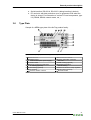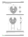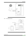
1
KEMRO KeTop T100 User's Manual V4.00 Translation of the original instructions Document : V4.00 / article no.: 57463 Filename : t100_bhen.pdf Pages : 144 . © KEBA 2009 Specifications are subject to change due to further technical developments. Details presented may be subject to correction. All rights reserved. A: KEBA AG, Gewerbepark Urfahr, A-4041 Linz, Tel.: +43 732 7090-0, Fax: +43 732 7309-10, E-Mail: [email protected] D: KEBA GmbH Automation, Leonard-Weiss-Straße 40, D-73037 Göppingen, Tel.: +49 7161 9741-0, Fax: +49 7161 9741-40, E-Mail: [email protected] US: KEBA Corp., 100 West Big Beaver Road, Troy, MI 48084, US, Tel.: +1 248 526-0561, Fax: +1 248 526-0562, E-Mail: [email protected] CN: Beijing Austrian KEBA Science and Technology Development Ltd., Room B516, Nan Xin Cang Tower, A22 Dong Si Shi Tiao, Dong Cheng District, Beijing, 100027, P.R. China, Tel. +86 10 6409-6592, Fax +86 10 6409-6312, E-Mail: [email protected] www.keba.com KeTop T100 Record of Revision Record of Revision Version Date Change in chapter Description changed by V3.20 07-2009 all Insert or adapt requirements (2006/42/EC, EN ISO 13849-1, ZT 05) lb V4.00 08-2009 all Release lb, kreu, mahr User's Manual V4.00 © KEBA 2009 3 Table of Contents Table of Contents 1 Introduction....................................................................................................................... 9 1.1 Purpose of the document........................................................................................ 9 1.2 Target groups, pre-conditions................................................................................. 9 1.3 Intended Use of the Handheld Terminal................................................................. 9 1.4 Notes on this document........................................................................................ 10 1.4.1 Contents of document............................................................................ 10 1.4.2 Not contained in this document.............................................................. 11 1.5 Documentation for further reading........................................................................ 11 1.6 Definition of terms................................................................................................. 11 1.7 Information about MD 2006/42/EC........................................................................ 11 1.7.1 Which devices have to comply with the new machine directive?........... 12 1.7.2 Quantitative safety relevant specifications for emergency stopbutton and enabling control device......................................................... 12 1.7.3 Relationship between Performance Level and Safety Integrity Level....................................................................................................... 12 1.7.4 Abbreviations.......................................................................................... 13 2 Safety notes.................................................................................................................... 14 2.1 Representation...................................................................................................... 14 2.2 2.2 General safety instructions.............................................................................. 14 2.3 Personnel safety instructions................................................................................ 16 3 General product description.......................................................................................... 18 3.1 Construction.......................................................................................................... 19 3.2 Ergonomic Features.............................................................................................. 20 3.3 Housing................................................................................................................. 20 3.4 Operating and Display Panel................................................................................ 20 3.5 Hardware............................................................................................................... 20 3.6 Type Plate............................................................................................................. 21 4 Connection...................................................................................................................... 22 4.1 Cable Entrance Area............................................................................................. 22 4.1.1 Adhesive label for CPU serial number and Ethernet (MAC)-address....................................................................................................... 22 4.2 Cable Routing in Cable Entrance Area................................................................. 22 4.2.1 Cable outlet RS-422-A........................................................................... 24 4.2.2 Cable outlet Ethernet.............................................................................. 24 4.3 Power Supply........................................................................................................ 24 4.4 Emergency Stop Button and grey Stop Button..................................................... 25 4.5 Enabling Switch..................................................................................................... 26 4.5.1 Functioning............................................................................................. 27 4.5.2 Example of Connection with PILZ PNOZ s6.1 Control Relay................. 29 4.6 Foreseeable Misuse of Enabling Switch............................................................... 30 4.7 Ethernet................................................................................................................. 31 4.7.1 Wiring diagram....................................................................................... 32 4.8 RS-422-A.............................................................................................................. 32 User's Manual V4.00 © KEBA 2009 5 Table of Contents 4.9 4.10 KeTop T100 4.8.1 Wiring diagram....................................................................................... 33 4.8.2 General information about the RS-422-A interface................................ 33 Serial port female connector S2 for Debug Interface (RS-232-C)......................... 33 PC Card Slot for PC Cards I, II, III........................................................................ 34 4.10.1 Inserting the PC Card............................................................................. 35 4.10.2 Removing the PC Card.......................................................................... 36 5 Membrane Keypad.......................................................................................................... 37 5.1 General Membrane Keypad.................................................................................. 37 5.1.1 7.7“ display (640x480 pixels).................................................................. 38 5.1.2 8.4“ display (800x600 pixels).................................................................. 39 5.2 Robotics Membrane Keypad................................................................................. 39 5.2.1 7.7“ display (640x480 pixels).................................................................. 40 5.2.2 8.4“ display (800x600 pixels).................................................................. 41 5.3 Numbering of LEDs............................................................................................... 41 6 Display............................................................................................................................. 43 6.1 Touch Screen........................................................................................................ 43 7 Software........................................................................................................................... 44 7.1 Windows CE.......................................................................................................... 44 7.2 Generation of Program for Windows CE............................................................... 45 7.3 KeTop API Design................................................................................................. 45 7.3.1 Common data types............................................................................... 45 7.3.2 Handling of Errors.................................................................................. 46 7.4 Functions............................................................................................................... 46 7.4.1 Functions for starting and closing........................................................... 46 7.4.2 Functions for Configuration.................................................................... 47 7.4.3 Functions for Reading the Configuration................................................ 48 7.4.4 Peripheral Functions.............................................................................. 49 7.4.5 LED Functions........................................................................................ 51 7.4.6 Other functions....................................................................................... 52 7.4.7 Functions for Subscribing Events........................................................... 53 7.5 Update API Design................................................................................................ 58 7.5.1 Handling of Errors.................................................................................. 58 7.6 Initialising.............................................................................................................. 58 7.6.1 Functions................................................................................................ 59 7.7 Program for Starting the Application and KeTop API............................................ 62 7.7.1 Functional description............................................................................ 62 7.7.2 Registry entries...................................................................................... 62 7.7.3 Example................................................................................................. 63 7.8 RDP - Connection via Remote Desktop Protocol.................................................. 64 7.8.1 RDP-Server (Remote-PC)...................................................................... 65 7.8.2 RDP-Client (PC)..................................................................................... 65 7.8.3 RDP-Client (KeTop)............................................................................... 65 7.9 KVC - KEBA Virtual Channel................................................................................ 70 7.9.1 Events of Server..................................................................................... 71 7.9.2 Data Transmission................................................................................. 71 7.9.3 Example: Interface on Server................................................................. 73 7.10 Remote Software ActiveSync................................................................................ 78 7.10.1 Data connection via RS-232-C debug interface..................................... 78 7.10.2 Data connection via USB client.............................................................. 79 6 User's Manual V4.00 © KEBA 2009 Table of Contents 8 KeTop - Specific Operating Instructions...................................................................... 80 8.1 Setting of Date and Time...................................................................................... 80 8.2 KeTop Configuration Tool (ConfigTool)................................................................ 81 8.2.1 Calibration of Joystick............................................................................ 81 8.2.2 Calibration of Potentiometer................................................................... 82 8.2.3 Display and Touch Screen Settings....................................................... 82 8.2.4 Setting the Handwheel to Zero............................................................... 83 8.2.5 Actions on next Startup.......................................................................... 83 8.2.6 Control of Buttons (Pushbuttons)........................................................... 84 8.2.7 Loading an Image File............................................................................ 85 8.2.8 Version Info............................................................................................ 86 8.2.9 Checking the Operating and Control Elements...................................... 86 8.3 Installation of Programs........................................................................................ 87 8.4 Saving Files........................................................................................................... 87 8.5 Transfering Files................................................................................................... 87 8.5.1 Transfer via external storage device (PC-card, CF-card, USBStick)...................................................................................................... 87 8.5.2 Transfer via network connection by SMB acces from PC to KeTop....... 87 8.5.3 Transfer via network connection by access from KeTop to the PC ....... 88 8.5.4 Transfer via ActiveSync.......................................................................... 88 9 Options............................................................................................................................ 89 9.1 Override Potentiometer......................................................................................... 89 9.2 Electronic Handwheel........................................................................................... 89 9.3 Illuminated Push-Button........................................................................................ 89 9.4 Key Switch............................................................................................................ 89 9.5 Selector Switch..................................................................................................... 90 9.6 Joystick................................................................................................................. 90 10 Accessories..................................................................................................................... 91 10.1 Wall Bracket without Height Adjustment plate KeTop WB090, WB095, WB120.................................................................................................................. 91 10.1.1 10.1.1 Dimensions (mm)........................................................................ 92 10.2 Wall Bracket with Height Adjustment plate KeTop WB 110.................................. 93 10.2.1 Height adjustment plate.......................................................................... 93 10.3 Junction Box JB 001............................................................................................. 94 10.3.1 Device description.................................................................................. 95 10.3.2 Connection............................................................................................. 96 10.3.3 Connection diagram............................................................................... 96 10.3.4 Shielding inside the Control Cabinet.................................................... 100 10.3.5 Mounting Instructions........................................................................... 101 10.3.6 Technical data of Junction Box JB 001................................................ 102 10.4 KeTop CB211 Connection Box........................................................................... 102 10.4.1 Construction......................................................................................... 103 10.4.2 Interior view.......................................................................................... 104 10.4.3 Technical data of the connection terminals.......................................... 104 10.4.4 Drilling template for wall mounting....................................................... 106 10.4.5 DIN Rail Holder Mounting Set KeTop DR200...................................... 107 10.4.6 Use of Connection Box......................................................................... 108 10.4.7 Minimum Bending Radius of Cable...................................................... 108 10.4.8 Technical Data of Connection Box KeTop CB211............................... 108 10.5 Connection Cable KeTop TTxxx......................................................................... 109 User's Manual V4.00 © KEBA 2009 7 Table of Contents 10.6 10.7 KeTop T100 Intermediate Cable KeTop IC2xx........................................................................ 111 Download Cable KeTop XD040.......................................................................... 112 11 Transport Conditions................................................................................................... 114 12 12 Disposal of the KeTop............................................................................................. 115 13 Technische Daten......................................................................................................... 116 13.1 Allgemein............................................................................................................ 116 13.2 Environmental conditions.................................................................................... 116 13.3 Housing............................................................................................................... 116 13.4 Processor and interfaces.................................................................................... 117 13.5 E-Stop ratings..................................................................................................... 117 13.6 Enabling device................................................................................................... 118 13.7 Accessories......................................................................................................... 118 13.8 Spare parts.......................................................................................................... 119 14 CE Conformity, Directives and Standards................................................................. 120 14.1 European Union Directives................................................................................. 120 14.2 Machinery Safety................................................................................................ 120 14.2.1 "Hazard and Risk Analysis".................................................................. 121 14.2.2 "Principles for the Integration of Safety"............................................... 121 14.2.3 "Technical Construction File"............................................................... 122 14.2.4 "State of the Art"................................................................................... 123 14.2.5 "Recognition of Conformity by means of Harmonised Standards"....... 123 14.2.6 Selection of Performance Level and Safety Categories in accordance with EN ISO 13849-1............................................................ 123 14.2.7 Application of Handheld Terminals in Special Operating Modes......... 124 14.2.8 Information about the Emergency Stop Button.................................... 125 14.2.9 Application of Emergency Stop Button and Stop Button on the Handheld Terminal............................................................................... 126 14.2.10 Information about Enabling Devices..................................................... 128 14.3 Electromagnetic Compatibility............................................................................. 130 14.3.1 The electromagnetic environment – interference sources, interference sinks and coupling paths..................................................... 130 14.3.2 EMC measures..................................................................................... 133 14.3.3 EMC measures on KeTop.................................................................... 137 14.4 List of the appropriate EC directives and applied standards............................... 141 14.4.1 EC directives........................................................................................ 141 14.4.2 Standards............................................................................................. 141 15 Conformity and Type Examination............................................................................. 143 15.1 EC Conformity Declaration.................................................................................. 143 15.2 EC Type-Examination Certificate........................................................................ 144 8 User's Manual V4.00 © KEBA 2009 Introduction 1 1.1 Introduction Purpose of the document This document describes the hand-held terminal KeTop T100. This document contains all specifications required by machinery directive 2006/42/EC. 1.2 Target groups, pre-conditions This document is intended for the following persons with corresponding preconditions: Target group Prerequisite knowledge and ability Technical basic education (advanced technical education, engineering degree or corresponding professional experience), Knowledge about: Project engineer ● the method of operation of a PLC, ● safety regulations, ● the application. Technical basic education (advanced technical education, engineering degree or corresponding professional experience), Knowledge about: Start-up technician ● safety regulations, ● the method of operation of the machine or system, ● fundamental functions of the application, ● system analysis and troubleshooting, ● the setting options at the operating devices. Technical basic education (advanced technical education, engineering degree or corresponding professional experience), Knowledge about: Service technician ● the method of operation of a PLC, ● safety regulations, ● the method of operation of the machine or system, ● diagnosis possibilities, ● systematic error analysis and troubleshooting 1.3 Intended Use of the Handheld Terminal The intended use of the Handheld Terminal covers tasks like watching and parametrizing up to operating of machines e.g.: ● Injection moulding machine ● Robots User's Manual V4.00 © KEBA 2009 9 Introduction KeTop T100 ● Machine tools ● Textile machines ● Printing machines ● Theater backdrops ● and similar in normal operating modes ● Automatic as well as ● Setting ● Teaching ● Testing ● and similar in half automatic or manual mode. Enabling switches and an emergency stop button (or halt-button) are the safety elements of the device. The Handheld Terminal is intended for fixed connection to a robot. Handheld Terminals for temporary connection must not have a red-yellow emergency stop button. In this case a handheld terminal with grey halt-button is available. To meet the safety category 3 PL d in accordance with EN ISO 13849-1, the safety functions are realized with 2 circuits. The selection of the Handheld Terminal which is suitable for the machine and the projecting of the additional functions must obey the necessary hazard analyses and risk assessment bounded by law. For intended use of the Handheld Terminal also please pay attention to chapter 14 "CE Conformity, Directives and Standards" on page 120. 1.4 Notes on this document This manual is integral part of the product. It is to be retained over the entire life cycle of the product and should be forwarded to any subsequent owners or users of the product. 1.4.1 Contents of document ● Safety Precautions ● General Instructions ● Connection ● Membran Keypad ● Display ● Software ● Specific Operating Instructions 10 User's Manual V4.00 © KEBA 2009 Introduction ● Options ● Accessories ● Transport Conditions ● Disposal ● Technical Data ● CE Conformity, Directives and Standards 1.4.2 Not contained in this document ● Mask description of the application 1.5 Documentation for further reading Doc.No. - 1.6 Description - Target group - Definition of terms This user's manual corresponds to machinery directive 2006/42/EC. The terms used in this manual that come from the machinery directive are the same as in the preceding MD 98/37/EC. Within standard EN 60204-1 the following term has changed: EN 60204-1:1997 Enabling device EN 60204-1:2006 Enabling control device (chapter 10.9) In order to avoid ambiguity for users this manual still uses the term of EN 60204-1:1997. 1.7 Information about MD 2006/42/EC The machine directive (MD) 2006/42/EC will be valid from 2009-12-29 (without any transition period). This means that all machines and safety components that will be brought to market after this date have to confirm this new MD and its harmonised standards. For handheld terminals from KEBA this means that besides the new machine directive also the standard EN ISO 13849-1:2008 will be used. EN ISO 13849-1 demands for the safety relevant component "enabling switch" the specification of category and Performance Level (PL) and for emergency stop-buttons and grey stop-buttons the specification of the B10d-value. These values can be found within the manuals in chapter 13.5 "E-Stop ratings" on page 117 and chapter 13.6 "Enabling device" on page 118. User's Manual V4.00 © KEBA 2009 11 Introduction 1.7.1 KeTop T100 Which devices have to comply with the new machine directive? This rule is valid for KEBA and its customers: Depending on the date the product has been put into circulation the new machine directive has to be applied or not. If the KeTop will be delivered in its end use after 2009-12-29, it will be put into circulation newly - even if it has been sold by KEBA at an earlier date. ● Devices complying with the old MD and that will be sent to KEBA for repair, can be repaired and delivered in compliance with the old MD. ● Customer sends old device for repair and will receive the same or another, equal device. ● Devices complying with the new MD and that will be sent to KEBA for repair, must be repaired and delivered in compliance with the new MD. 1.7.2 Quantitative safety relevant specifications for emergency stop-button and enabling control device ● Emergency stop-button: KEBA specifies a B10d-value. Other values (e.g. SIL, PL, Category) cannot be specified by KEBA. Explanation: KEBA solely delivers the control element, but no evaluation of the element. The customer has to connect the emergency stop to his application on his own. Depending on the connection of the emergency stop to the machine the SIL- or category and PL-value can be determined. ● Enabling control device: KEBA specifies category and PL in accordance to EN ISO 13849-1. Derived from this value KEBA also specifies a PFH- and MTTFd-value in accordance to EN ISO 13849-1. SIL (in accordance to EN 62061 or EN 61508) cannot be specified by KEBA. Explanation: The enabling control devices has been evaluated in accordance to EN ISO 13849-1. A B10d-value is not available for the enabling control device, as this device consists of the mechanic element and the electronic evaluation. This means that KEBA specifies MTTFd- and DCvalues (and derived from these values also Category, PL and PFH) for the enabling control device as a whole (starting from the pushbutton up to the clamps within the junction box). 1.7.3 Relationship between Performance Level and Safety Integrity Level When evaluating safety functions by IEC EN 62601 the PL can be transformed into SIL by following the equivalence table of EN ISO 13849-1. Table 4 (EN ISO 13849-1) - Relationship between Performance Level (PL) and Safety Integrity Level (SIL) 12 Performance Level (PL) by EN ISO 13849-1 Safety Integrity Level (SIL) by IEC 61508-1 a no corresponding value User's Manual V4.00 © KEBA 2009 Introduction b 1 c 1 d 2 e 3 Table 3 (EN ISO 13849-1) - Performance Level (PL) 1.7.4 Performance Level (PL) Average probability of a dangerous breakdown per hour 1/h a ≥ 10-5 to < 10-4 b ≥ 3 x 10⁻⁶ to < 10-5 c ≥ 10-6 to < 3 x 10⁻⁶ d ≥ 10-7 to < 10-6 e ≥ 10-8 to < 10-7 Abbreviations Abbreviation User's Manual V4.00 © KEBA 2009 Term B10d - MTTFd Mean Time to Dangerous Failure DC Diagnostic Coverage PL Performance Level PFH Probability of Failure per Hour SIL Safety Integrity Level 13 Safety notes 2 2.1 KeTop T100 Safety notes Representation At various points in this manual you will see notes and precautionary warnings regarding possible hazards. The symbols used have the following meaning: DANGER! ● indicates an imminently hazardous situation which will result in death or serious bodily injury if the corresponding precautions are not taken. WARNING! ● indicates a potentially hazardous situation which can result in death or serious bodily injury if the corresponding precautions are not taken. CAUTION! ● means that if the corresponding safety measures are not taken, a potentially hazardous situation can occur that may result in property injury or slight bodily injury. CAUTION ● CAUTION used without the safety alert symbol indicates a potentially hazardous situation which, if not avoided, may result in damage to property. ● This symbol reminds you of the possible consequences of touching electrostatically sensitive components. Information Useful practical tips and information on the use of equipment are identified by the “Information” symbol. They do not contain any information that warns about potentially dangerous or harmful functions. 2.2 2.2 General safety instructions The device was developed, manufactured, tested and documented in ac-cordance with the applicable safety standards. If you follow the instructions regarding safety and use as described in this manual (see chapter 1.3 "Intended Use of the Handheld Terminal" on page 9), the product will, in the normal case, neither cause personal injury nor damage to machinery and equipment. The instructions contained in this manual must be precisely followed in all circumstances. Failure to do so could result in the creation of potential sources of danger or the disabling of safety features integrated in the handheld terminal. 14 User's Manual V4.00 © KEBA 2009 Safety notes Apart from the safety instructions given in this manual, the safety precautions and accident prevention measures appropriate to the situation in question must also be observed. Handling of KeTop You have chosen a high-quality KeTop that is equipped with highly sensitive state-of-the-art electronics. To avoid malfunctions or damage through improper handling, follow these instructions during operation. WARNING! The following application areas are expressly excluded for the KeTop: ● Use in areas prone to explosion or fire ● Use in mining ● Outdoor use Other products must be used for these applications! The KeTop housing must not be opened (acception: cable entrance area) , as the KeTop is sensitive to electrostatic discharge. User's Manual V4.00 © KEBA 2009 15 Safety notes KeTop T100 CAUTION 2.3 ● Turn off the power supply before opening the cable entrance area of the KeTop. Otherwise the components could be destroyed or undefined signals could occur. ● Make sure that nobody can fall over the cable to avoid that the device falls to ground. ● Take care not to squeeze and thus damage the cable with any object. ● Do not lay the cable over sharp edges to avoid damaging the cable sheath. ● If you do not use the device, hang it into the wall bracket KeTop WBxxx provided for storage. ● Do not lay down the device with the operating side facing down to avoid damaging the operating elements. ● Never lay the device onto unstable surfaces. It could fall to ground and thus be damaged. ● Never lay the device close to heat sources or into direct sunlight. ● Avoid exposing the device to mechanical vibrations, excessive dust, humidity or to strong magnetic fields. ● Never clean the device, operating panel and operating elements with solvents, scouring agent or scrubbing sponges. For cleaning the device, use a soft cloth and a bit of water or a mild cleaning agent. ● Make sure that no foreign objects or liquids can penetrate into the device. Check at regular intervals the protective covers of the device, if all housing screws are firmly tightened and if the housing or the cable entry is damaged. ● If the device shows any defect, please send it, including a detailed error description, to your supplier or the relevant after-sales service office. ● If the KeTop is equipped with a touch screen, then operate the touch screen with fingers or use a touch-pen. Never use sharp objects (e.g. screwdriver,...) for operating the touch screen. This could damage the touch screen. Personnel safety instructions WARNING! Danger to persons by electric shock! ● Only supply the device with power from voltage sources having protective extra-low voltage (e.g. SELV or PELV acc. to IEC 61131-2) ● Only connect voltages and circuits which are safely separated from dangerous voltages (e.g. by means of sufficient insulation) to connections, terminals or interfaces up to a rated voltage of 50 V. CAUTION! Danger of fire in case of component failure! ● 16 In final application, make sure the 24 V DC power supply to the operator panel is adequately fused! Max. permissible fuse is 3.15 A! User's Manual V4.00 © KEBA 2009 Safety notes WARNING! ● For the right projecting of the Handheld Terminal the manufactorer must enforce a hazard and risk analysis. The following safety aspects must be considered: - Right cable length for limitation of workspace. - Is an emergency stop button necessary and permissible? - Is the safety category for the application sufficient? User's Manual V4.00 © KEBA 2009 ● From the operating place the operator must have a good view at the hazard area. ● The device may be operated in faultless condition only and the operating instructions must be observed. ● The operator must have a sufficient educational level and must know details of intended use described in the user’s manual. ● The safety advices in the following chapters must be considered absolutely. ● Further informations to safety and EMC are included in chapt. "CE Conformity, Directives and Standards". They must be considered absolutely. 17 General product description 3 KeTop T100 General product description The handheld terminal KeTop is a portable operating and display device with rugged design and Windows-CE compatible electronics. Using a high-performance processor and providing a serial interface and Ethernet, the KeTop is ideal for a great variety of applications. All tasks can be solved graphically and in color, and operation is intuitive using a touch screen. Instead of rotating mass memories such as floppy disk and hard disk drives that are not suitable for rough environmental conditions, the KeTop uses scalable FLASH and RAM banks. The KeTop provides a Windows CE platform for applications generated with common visualization tools or with C#, Visual Basic.NET or Visual C++. Moreover, the KeTop can be connected as a client to a Win NT, Win 2000 or Windows XP server. Through the use of optional operating and control elements, the KeTop can easily be adapted to the specific application. Weiters ist es auch möglich, das KeTop als Client an einen Windows NT-, Windows 2000-, oder Windows XP-Server anzubinden. 18 User's Manual V4.00 © KEBA 2009 General product description 3.1 Construction Fig.3-1: Construction of KeTop T100 1 ... override potentiometer (option) 3 ... emergency stop switch (twin circuit) or stop switch (option) 4b... further status LEDs (option) 6 ... color STN LC display with touch screen: 7,7“ VGA resolution (640 x 480) or 8,4“ SVGA resolution (800 x 600, option) 8 ... 1 location for (option): illuminated pushbutton (momentary 0), illumniated pushbutton (momentary I), illuminated pushbutton (maintaining I/0), 3-position key switch (I-0-II), 3-position selector switch (I-0-II) 10... multigrip handle 12... strain relief for connection cable (delivered with the cable) 14... blind plug for cable outlet not used (to meet protection degree IP54) User's Manual V4.00 © KEBA 2009 2 ... electronic handwheel or joystick (option) 4a... 2 status LEDs (standard) 5 ... membrane keypad with tactile feedback 7 ... 2 locations for (option): illuminated push-button (momentary 0), illumniated push-button (momentary I), illuminated push-button (maintaining I/0) 9 ... two 3-position enabling switches (left and right), twin circuit 11... PC card cover 13... cable entrance area (lid) 19 General product description KeTop T100 Information All optional operating elements are described in chapter 9 "Options" on page 89 . 3.2 Ergonomic Features ● Multigrip handle ● Round housing ● Different holding positions ● Operation by right-handed and left-handed people ● Desk top operation ● Operation in wall bracket ● The cable outlet can be on the left or right side of the housing. ● Easy-to-read display 3.3 Housing ● Vibration- and shock resistance ● Housing made of non-flammable material (UL 94-V0), impact-resistant, withstands water, cleaning agents (alcohol and tensides), oil, drilling oils, grease and lubricants ● Twin shell, extremely sturdy housing. Drop-tested on industrial flooring from a height of 0.75 m (29.5 in, SVGA) and 1 m (39.4 in, VGA). 3.4 Operating and Display Panel ● Membrane keys with tactile feedback ● 2 status LEDs ● Buzzer in upper part of housing ● Resistive touch screen, to be operated with finger or stylus ● Backlit color STN LC display: 7.7“ VGA (640x480 pixels) or 8.4“ SVGA (800x600 pixels) 3.5 Hardware ● CPU Intel StrongARM SA-1110/206 MHz ● Memory: ● DRAM: max. 128 MB, FLASH: max. 64 MB ● Interfaces: ● Ethernet 20 User's Manual V4.00 © KEBA 2009 General product description ● Serial interface: RS-422-A, RS-232-C (debug interface in device) ● PC card slot, with dust protection cover to guarantee IP54 when the device is closed: For connection of various PC card components, type I-III (DRAM, SRAM, network cards, etc.). 3.6 Type Plate Sample of a KEBA type plate of the KeTop product family: Fig.3-2: 1 ... 3 ... 5 ... 7 ... 9 ... 11... 13... 15... 17... User's Manual V4.00 © KEBA 2009 Sample type plate of the KeTop product family Manufacturer Material name Technical data (here: power supply) Serial number Date of production (month/year) UL marking (optional) BG marking (optional) CE marking Revision number of device 2 ... 4 ... 6 ... 8 ... 10... 12... 14... 16... 18... Manufacturer's address Further information (optional) Bar code SIBE marking (optional) Ambient temperature ROHS marking Advice for electronic scrap regulation ÖVE marking (optional) Material number 21 Connection 4 4.1 KeTop T100 Connection Cable Entrance Area Fig.4-1: 4.1.1 Adhesive label for CPU serial number and Ethernet (MAC)-address Fig.4-2: 4.2 Cable entrance area of KeTop T100 Adhesive label for CPU serial number and Ethernet-address Cable Routing in Cable Entrance Area After opening the cable entrance area, the connecting lines can be routed as described in the following chapters. Before opening the KeTop please pay attention to the following safety instructions: 22 User's Manual V4.00 © KEBA 2009 Connection Information Instructions for opening the cable entrance area: ● Lay the KeTop with the display facing down onto a plane and clean table (preferable on ESD pad) and take care not to damage the KeTop and its operating elements. ● For opening and closing the cable entrance area use the following type of screwdriver: "Phillips size 2". Instructions for modifications in the cable entrance area: ● Unplug the main connector (S19) by pulling on its wires with your fingers. Do not use any sharp objects. ● For unplugging the RJ-45 jack (S4 oder S6), actuate the locking lever: Fig.4-3: Uplugging main connector (S19) and RJ-45 jack (S4 oder S6) 1 ... main connector 2 ... RJ-45 jack WARNING! ● Make shure that the main connectors (S19) and the RJ-45 jack (S4 oder S6) correctly snap in when you plug them in. Otherwise the emergency stop functionality (S19) or the correct shielding (S4 oder S6) might not be given any more. ● Validate the emergency stop-functionality before re-starting the KeTop. Information Instructions for closing the cable entrance area: Make sure that ● the sealing is clean, not damaged and correctly positioned in the cable entrance area, ● no cables are squeezed in, ● the cover of the cable entrance area is attached again with all 6 screws (torque: 0.4 bis 0.5 Nm). Otherwise the protection degree cannot be guaranteed. User's Manual V4.00 © KEBA 2009 23 Connection KeTop T100 Information The position of connectors S11 (RS-422-A) and S4 (Ethernet) in KeTop T50VGA is just the other way round like in KeTop T100. Users of both devices please take care for this! 4.2.1 Cable outlet RS-422-A Fig.4-4: 4.2.2 Cable outlet Ethernet Fig.4-5: 4.3 Cable outlet on left and right side if the RS-422-A interface is used. Cable outlet on left and right side if the Ethernet interface is used. Power Supply WARNING! The device meets the safety class III in accordance with EN61131-2. The 24V power supply for the equipment must be guaranteed through safe isolation of the low-voltage circuits from dangerous-contact voltage circuits (e.g. by safety transformers or similar facilities). WARNING! A safe isolation between safety extra-low voltage and voltage that is dangerous for human contact has to be assured. WARNING! The power supply circuit must be protected with a 3.15 A fuse. Specification of power supply lines in the KeTop TTxxx connection cable: 24 User's Manual V4.00 © KEBA 2009 Connection ● Cross section: AWG24 (0.24mm²) ● Material: zinc-coated copper strand ● Line resistance: ≤ 90 Ohm/km (≤ 145 Ohm/mile) The nominal supply voltage directly on the handheld terminal (without KeTop TTxxx connection cable) is: +24 V DC (fully operational in the range 18 V DC - 32 V DC). Maximum interruption time of supply voltage: ≤ 10 ms (according to IEC 61131) Power consumption: 7.2 W (400 mA at 18 V DC, 300 mA at 24 V DC) 4.4 Emergency Stop Button and grey Stop Button The emergency stop button respectively the grey stop button used on the KeTop features two circuits. The contacts are normally closed. The red-yellow emergency stop button of the handheld terminal meets the requirements of the EN ISO 13850. It must be designed as an emergency stop of category 0 or category 1 (see EN 60204-1 chapter 9.2.5.4.2) on the basis of the risk assessment for the machine. The connection of the positive-break contacts to an appropriate monitoring system must meet the safety category (in accordance with EN ISO 13849-1) which is defined by means of the risk assessment (in accordance with EN ISO 14121-1) of the machine. Optionally the KeTop is also available with a grey stop button instead of the red-yellow emergency stop button. In principal the grey stop button has the same functionality as the red-yellow emergency stop button. If the handheld terminal is not plugged in, the grey color of the stop button should avoid the usage of the non-effective (emergency) stop button in dangerous situations. The grey stop button fulfils also all mechanical aspects of the EN ISO 13850 and differs from the emergency stop button only by its color. User's Manual V4.00 © KEBA 2009 25 Connection KeTop T100 WARNING! ● Not fully functional emergency stop devices may have fatal consequences! Emergency stop switches which are red-yellow marked must be effective under all circumstances in all operating modes of a machine or plant. Store handheld terminals with not operational red-yellow emergency stop switches on a place where the operator cannot see it, so that he can not mistake the device. Handheld terminals which are plugged in and out frequently for temporarely use, must not have a red-yellow emergency stop switch. Such devices must be equipped with a grey stop switch. ● Resetting an activated emergency stop facility must not result in uncontrolled start-up of machines or installations. ● The emergency stop button does not replace other safety facilities. ● The emergency stop button on the handheld terminal does not replace the emergency stop buttones to be mounted directly on the machine. ● Some mechanical errors in emergency stop switches can be recognized at operation only. Test the function of the emergency stop switch when the device had been exposed to mechanical shock (e.g. it had been fallen on the ground). Additionally the emergency stop switch must be tested cyclic (6 monthly). Watch the machine stopping after the emergency stop switch had been pushed. ● 4.5 For further informations to emergency stop switch observe chapter 14 "CE Conformity, Directives and Standards" on page 120. Enabling Switch The KeTop is equipped with two enabling switches, one at the left and one at the right side of the device. This allows a left- and right-hand operation of the enabling switch. Both enabling switches are equivalent and parallel switched. So for enabling only one of both enabling switches must be activated. The enabling switch consists of a 3-position operating element and an separated evaluation electronics. An essential feature are the continuous twochannel circuits beginning from the actuating elements up to the connecting terminals. For the evaluation circuits different technologies and circuits are used. Due to the electronic switching contacts, their lifetime does not depend on the load provided the nominal values of the load (ohmic, inductive and capacitive) are not exceeded. The switching elements of the enabling switches are protected against reversed polarity. The outputs of both circuits are protected against short circuits and overload. Circuit 1: thermal protective circuit Circuit 2: fold back line 26 User's Manual V4.00 © KEBA 2009 Connection 4.5.1 Functioning The actuating element consists of two symmetrically arranged slides. The position of these slides is detected by electrical switches and transmitted to the evaluation electronics. Positions of enabling switch: Position Function Enabling switch Contacts 1 home position is not pressed enabling outputs are open 2 enabling is pressed enabling outputs are closed 3 panic is pressed strong enabling outputs are open Tab.4-6: Positions of the enabling switch WARNING! The enabling switch must be tested cyclic (6 monthly) by pressing the panic position. Watch the machine performing the panic function after pressing the enabling switch. 4.5.1.1 Enabling Fig.4-7: 4.5.1.2 Contact travel diagram for enabling Panic The pushing of the actuating elements into the panic position is evaluated in a way that the enabling position is skipped when the actuating elements are released. User's Manual V4.00 © KEBA 2009 27 Connection KeTop T100 Fig.4-8: Contact travel diagram for panic Information At the KeTop, the enabling switches always feature two circuits. To meet the safety category 3 PL d in accordance with EN ISO 13849-1, the enabling switch must be realized with 2 circuits and these circuits have to be monitored on short circuits. The safety category 3 PL d means, that one failure must not lead to the loss of the safety function, and whenever possible, the single failure is detected. The example of connection in chapter 4.5.2 "Example of Connection with PILZ PNOZ s6.1 Control Relay" on page 29 shows how the safety category 3 PL d can be fulfilled by the enabling switch up to the output terminal K4 within the connection box. The entire concept of the machine must be laid out according to the principles of safety category 3 PL d. The monitoring of the simultaneity by the control relay is necessary, because otherwise maybe a failure culmination would not be recognised and this would cause the loss of safeness: Example: If one circuit of the enabling device switches to the enabled state as a result of a failure and after some time the second circuit also switches to the enabled state as a result of an failure, then no de-energisation by the enabling device would be possible. Further the EN 60204-1 prescribes that the enabling switches shall be connected to a category 0 stop or a category 1 stop, that means the energy must be switched off. For calculation of the PL for the safety function "enabling" the PL- and B10dvalues of all involved components have to be included. For details for calculating the PL for the whole safety function see EN ISO 13849-1, chapter 6.3, appendix H and appendix I. 28 User's Manual V4.00 © KEBA 2009 Connection 4.5.2 Example of Connection with PILZ PNOZ s6.1 Control Relay Fig.4-9: 4.5.2.1 Suggested wiring of enabling swithches to fulfill safety category 3 PL d for the enabling switch with PILZ control relay. Also follow the instructions described in the PILZ operating manual about the device PNOZ s6.1. For calculation of the whole safety function "enabling" the control relay and all subsequent components have to be considered. Functional procedure ● Only if both channels are activated "simultaneously (≤0,5s)" (by pressing one of the enabling switches) both output relays K1 and K2 will energize and the output contacts 13-14 and 23-24 will close. ● The output relays K1 and K2 will not energize if ● only one enabling channel is activated (in case of a defect), User's Manual V4.00 © KEBA 2009 29 Connection KeTop T100 ● the tolerance value for the simultaneity period is exceeded, ● the feedback control loop S34 is open. ● If one enabling channel is deactivated after being simultaneously activated (by releasing the enabling switch or in case of a defect), the output relays K1 and K2 will return to their initial position again. The forced-guided output contacts 13-14 and 23-24 will open. The output relays will energize again only after both enabling channels have been deactivated and simultaneously activated once again. In this way the enabling switches avoid that one single error makes the safety function inoperational. A single error will be recognized at the next cycle at the latest, identifying that re-enabling is no longer possible. In case of short circuit the control relay switches to ERROR and has to be turned OFF and ON again after resolving the error. 4.6 Foreseeable Misuse of Enabling Switch Foreseeable misuse means the not allowed fixing of the enabling switch in the enabling position. The foreseeable misuse of the enabling switch must be restricted. The following measures causing the stop of the machine in the manual mode are recommended: ● Inquiry of the enabling switch when turning on the machine/plant and inquiry of the enabling switch when changing the operating mode from automatic to manual (The enabling switch must not be in the enabling position.). ● The enabling switch must be released within a defined period and pushed into the enabling position again. The length of the period must be defined according to the activity. WARNING! 30 ● The enabling switch is only suitable as safety function if the operator activating the enabling switch recognizes the dangerous situation in time so that he can immediately take the necessary measures to avoid such situations. As additional measure reduced speed of the movement can be necessary. The allowed speed must be determined by means of a risk assessment. ● The enabling switch is only used to enable commands for performing dangerous movements. The commands themselves must be activated by a separate operating element (key on handheld terminal). ● Only the person who operates the enabling switch is allowed to work in the dangerous area. ● For further informations regarding the enabling switch please pay attention to chapter 14 "CE Conformity, Directives and Standards" on page 120. User's Manual V4.00 © KEBA 2009 Connection 4.7 Ethernet The standard version of the KeTop is equipped with an Ethernet interface. This interface is based on the 10BaseT specification and suitable for the half-duplex mode (the operation with 100Mbit requires a special connection cable). The data communication for these interfaces takes place via the Ethernet connector S4 (marking: ETHERNET) in the cable entrance area of the KeTop. The following interface parameters are defined and cannot be changed: ● 10 MBit (100MBit with appropriate cable possible) ● TCP/IP protocol The Ethernet interface is selected under Windows CE as follows: Start ▶ Settings ▶ Control Panel ▶ Network and Dial-up Connections: Here you can select the Ethernet on-board interface SMSC911x11. WARNING! If the KeTop and the control do not communicate via a point-to-point connection, it may happen that the keypad data, for example, are transmitted with a delay. Therefore it is advisable to establish the connection between the control and the KeTop only via an Ethernet switch which enables a point-to-point connection. The positions of the Dip switches in the cable entrance area are not relevant for this interface. If an Ethernet PC card is inserted into the PC card slot, the internal Ethernet interface must be deactivated. The selection between the internal Ethernet or the PC card Ethernet interface is made in the „ConfigTool“. See chapterchapter 8.2 "KeTop Configuration Tool (ConfigTool)" on page 81. User's Manual V4.00 © KEBA 2009 31 Connection 4.7.1 KeTop T100 Wiring diagram Fig.4-10: 4.8 KeTop T100 with Ethernet via connection box KeTop CB211 RS-422-A The serial interface will operate asRS-422-A. The communication takes place via the COM/SIO connector S11 in the cable entrance area of the KeTop. Information The simultaneous use of the Ethernet interface and the RS-422-A interface is not possible. The RS-422-A interface assigned to the COM 5 interface port is in the software. The interface parameters are set via the WIN32API in the Windows operating system. 32 User's Manual V4.00 © KEBA 2009 Connection 4.8.1 Wiring diagram Fig.4-11: 4.8.2 Connection of KeTop T100 with RS-422-A via connection box KeTop CB211 General information about the RS-422-A interface ● The A terminal of the generator shall be negative with respect to the B terminal for a binary 1 (MARK or OFF) state. ● The A terminal of the generator shall be positive with respect to the B terminal for a binary 0 (SPACE or ON) state. To identify the lines, the voltage between the lines A and B can be measured by means of a voltameter. 4.9 Serial port female connector S2 for Debug Interface (RS-232-C) Using the "Boot-Loader" software, the "serial port" interface can be used for debugging and for downloading software. Using the remote software ActiveSync, it can be used for adjusting and transmitting data from and to a PC. For that purpose, the download cable KeTop XD040 is available. The following interface parameters are defined and cannot be changed: ● 115200 baud ● 8 data bits ● 1 stop bit ● no parity ● no handshake The debug interface is assigned to the COM 1 interface port in the software. The positions of the Dip switches in the cable entrance area are not relevant for this interface. User's Manual V4.00 © KEBA 2009 33 Connection 4.10 KeTop T100 PC Card Slot for PC Cards I, II, III The following list gives an overview about the tested PC cards and their manufactors. These PC cards are recommended for the use in the KeTop. ATA flash cards: ● Manufacturer: Kingston, SanDisk, Kingmax, Viking Type: all PC cards type II Memory sizes: 8 MB and more PC card adapter for CompactFlash (CF) cards: ● Manufacturer: Hama Type: PC card adapter CF type II, Hama art. no. 56949 ● Manufacturer: Kingston Type: CF/ADP Compact Flash PC card Adapter ● Manufacturer: Ultron Type: UPA-150 PCMCIA adapter for compact flash card Ethernet cards: ● Manufacturer: Socket (http://www.socketcom.com) Name: LP-E Ethernet Card Type: PC cards type II Transmission rate: 10 Mbit/s Special features: NE2000 compatible ● Manufacturer: Orinoco (http://www.wavelan.com) Name: WaveLan Silber IEEE 802.11 Transmission rate: 11 Mbit/s Special features: Wireless LAN card Modem cards: ● Manufacturer: TDK (http://www.tdksys.com/Products/5660.html) Name: Global Freedom 5660 Type: PC cards type II Information ● The KeTop does not support CardBus cards. ● PC cards which use 12 V programming voltage are not supported by the KeTop. ● SRAM cards are not supported by Windows CE. 34 User's Manual V4.00 © KEBA 2009 Connection 4.10.1 Inserting the PC Card User's Manual V4.00 © KEBA 2009 35 Connection 4.10.2 36 KeTop T100 Removing the PC Card User's Manual V4.00 © KEBA 2009 Membrane Keypad 5 5.1 Membrane Keypad General Membrane Keypad The keypad assignment is stored in the registry and defined for the general membrane keypad as follows: Key Labelling Windows Virtual Key Code Hex Dec ESC VK_ESCAPE 0x1B 27 Menu VK_MENU 0x12 18 Numpad figures 0-9 VK_0-9 0x30 - 0x39 48 - 57 Dot (.) VK_PERIOD 0xBE 190 Minus (-) VK_OEM_MINUS 0xBD 189 Enter VK_RETURN 0x0D 13 Backspace VK_BACK 0x08 8 Tabulator VK_TAB 0x09 9 Page Down VK_NEXT 0x22 34 Page Up VK_PRIOR 0x21 33 Cursor Up VK_UP 0x26 38 Cursor Left VK_LEFT 0x25 37 Cursor Right VK_RIGHT 0x27 39 Cursor Down VK_DOWN 0x28 40 Illuminated push-button, left VK_F13 0x7C 124 Key switch/selector switch, left VK_F14 0x7D 125 Key switch/selector switch, right VK_F15 0x7E 126 Illuminated push-button, right VK_F16 0x7F 127 Depending on the size of the display, two general membrane keypads are available: User's Manual V4.00 © KEBA 2009 37 Membrane Keypad 5.1.1 7.7“ display (640x480 pixels) Fig.5-1: 38 KeTop T100 General membrane keypad for 7.7“ display User's Manual V4.00 © KEBA 2009 Membrane Keypad 5.1.2 8.4“ display (800x600 pixels) Fig.5-2: 5.2 General membrane keypad for 8.4“ display Robotics Membrane Keypad The keypad assignment is stored in the registry and defined for the robotics membrane keypad as follows: User's Manual V4.00 © KEBA 2009 Key Labelling Windows Virtual Key Code Hex Dec Page Down VK_NEXT 0x22 34 Page Up VK_PRIOR 0x21 33 Cursor Up VK_UP 0x26 38 Cursor Left VK_LEFT 0x25 37 Cursor Right VK_RIGHT 0x27 39 Cursor Down VK_DOWN 0x28 40 Menu VK_MENU 0x12 18 Enter VK_RETURN 0x0D 13 Delete VK_DELETE 0x2E 46 ESC VK_ESCAPE 0x1B 27 Help (?) VK_SHIFT + VK_SLASH 0x10 + 0xBF 16 + 191 Start VK_1 0x31 49 39 Membrane Keypad KeTop T100 Stop VK_0 0x30 48 V- no VK Code defined 0xC1 193 V+ no VK Code defined 0xC2 194 A1- no VK Code defined 0xC3 195 A1+ no VK Code defined 0xC4 196 A2- no VK Code defined 0xC5 197 A2+ no VK Code defined 0xC6 198 A3- no VK Code defined 0xC7 199 A3+ no VK Code defined 0xC8 200 A4- no VK Code defined 0xC9 201 A4+ no VK Code defined 0xCA 202 A5- no VK Code defined 0xCB 203 A5+ no VK Code defined 0xCC 204 A6- no VK Code defined 0xCD 205 A6+ no VK Code defined 0xCE 206 Z+ no VK Code defined 0xCF 207 Z- no VK Code defined 0xD0 208 Depending on the size of the display, two robotics membrane keypads are available: 5.2.1 7.7“ display (640x480 pixels) Fig.5-3: 40 Robotics membrane keypad for 7.7“ display User's Manual V4.00 © KEBA 2009 Membrane Keypad 5.2.2 8.4“ display (800x600 pixels) Fig.5-4: 5.3 Robotics membrane keypad for 8.4” display Numbering of LEDs Numbering of LEDs This chapter describes the numbering of the keyboard LEDs and push-button LEDs. The LED number is needed for activating the LED. A LED can be activated in two ways: ● via KeTop API design (see chapter 7.4.5 "LED Functions" on page 51) ● via KVC – KEBA Virtual Channel (see chapter 7.9.3 "Example: Interface on Server" on page 73) User's Manual V4.00 © KEBA 2009 41 Membrane Keypad Fig.5-5: 42 KeTop T100 Numbering of LEDs on KeTop User's Manual V4.00 © KEBA 2009 Display 6 Display The KeTop is available with two displays which differ as to their resolution and screen diagonals: Display 7.7“ Display 8.4“ Type: graphics-capable color STN LCD graphics-capable color TFT display Size: 7.7“ (160 x 120 mm) 8.4“ (175 x 130 mm) Resolution: VGA 640 x 480 pixels SVGA 800 x 600 pixels Representation: 256 colors 65535 colors Background lighting: CCFT cold cathode tube CCFT cold cathode tube Touch screen: analog-resistive analog-resistive The lifetime of the background lighting (40,000 h) can be increased through the activation of a screen saver via the control panel. Procedure: Start ▶ Settings ▶ Control Panel ▶ Display ▶ Folder Backlight Select the function „Automatically turn off backlight while on external power“. Here you can enter the turn-off time (30s to 30min). 6.1 Touch Screen If the touch screen is not operated with the finger, we recommend using a touch stylus, for example touch styluses of PDAs by PALM or SONY. The touch screen is already calibrated when the KeTop is delivered. No further calibration is required. If a re-calibration is required for any reason (humidity of air, temperature, etc.), perform the calibration procedure under Windows CE as follows: Start ▶ Settings ▶ Control Panel ▶ Stylus ▶ Calibration ▶ Recalibrate For the calibration you can also use the ConfigTool. See chapter 8.2 "KeTop Configuration Tool (ConfigTool)" on page 81. User's Manual V4.00 © KEBA 2009 43 Software 7 7.1 KeTop T100 Software Windows CE The KeTop is delivered with pre-installed software that is stored in the flash of the device. This software is also called "Image" since it combines all software contents in one file. The image contains the Windows CE operating system core and possibly additional applications. The image is created by means of the MS Platformbuilder for Windows CE. This description is valid for images from version 1.00. (Get image version on KeTop as follows: Start ▶ Programs ▶ KeTop ▶ Version) Software of Standard KeTop: ● Operating system Windows CE 4.2: ● System control ● Command Prompt ● Windows Explorer ● Pocket Internet Explorer ● Flash File System: ● IPSM (Intel Persistent Storage Manager) ● Pre-installed application programs: ● Pocket Notepad ● RDP-Client (Remote Desktop Connection) ● Pocket Registry Editor (\windows\regedit.exe) ● Active Sync ● KeTop-specific software (see Start ▶ Programs ▶ KeTop): ● KeTop Configuration Tool (extension in system control for configuration of contrast, background lighting, screensaver, touch screen and joystick calibration, clearing of registry, image update, ..) ● KEBA Virtual Channel (KVC) ● Registry Backup ● SetTime, temporary time and date entry ● TouchClean, Touch Cleaning Application ● Version, overview of versions ● Toggle sip (software keyboard) ● Test tools: ● TestSerial, test program for serial interfaces (\windows\testserial.exe) ● Reset (\windows\reset.exe) 44 User's Manual V4.00 © KEBA 2009 Software 7.2 Generation of Program for Windows CE The user can easily generate programs for Windows CE. Programming is similar to an application for a standard MS Windows NT PC. Under Windows CE, only the number of available WIN32-APIs is limited. Prerequisites for Application Programming: ● Microsoft eMbedded Visual C++ 4.0, Visual Studio 2003 / 2005 ● SDK (Software Development Kit) by manufacturer of Windows CE device (KEBA). The SDK provides to the programming environment the processor-dependent header and library files of the OEM adaptation. (If special hardware-dependent functions of the KeTop should be used, the SDK of the KeTop must be installed subsequently since the standard SDK for HPC (Handheld PC) and HPC Pro (Handheld PC Professional) does not take into account certain customer-specific adaptations.) 7.3 KeTop API Design The entire SDK is implemented in a single dynamic link library (DLL). All functions described in this document are exported from the DLL <\windows\KeTopAPI.dll>. This file and the corresponding SDK are contained on the CD "KeTop SK001". The following platform names are assigned to the KeTops: KeTop T100: KETOPT100 KeTop T50VGA: KETOPT50VGA KeTop T41: KETOPT41 System files that are copied to \windows directory by Visual Studio remain stored permanently. For this reason, these files must be copied manually to the directory \IPSM\windows (must be created by the user if necessary). In case of a restart of Windows CE, these files are automatically copied to the \windows directory. Therefore these files will be available for the operating system and after a restart. 7.3.1 Common data types This section contains a detailed description of the common data types for the communication with the handheld terminal. For further information, see TpuHwDataTypes.h. User's Manual V4.00 © KEBA 2009 INT8 Signed 8 bit integer variable. UINT8 Unsigned 8 bit integer variable. BacklightStat Enum, displays the backlight status JoystickPos Struct, for joystick data. Status Struct Describes the startup state of the device. EventMsg Enum, describes the event message received. 45 Software 7.3.2 7.3.2.1 KeTop T100 EventMsgDomains Enum, describes the events a handler has been subscribed to. eventCallback Function pointer to callback function. Handling of Errors Rules ● All functions expecting any input parameter check if the parameter is located inside the range and if its data type is correct. If a parameter is located outside the range the function will return INVALID_ARG_RANGE. ● All functions expecting a pointer for output data as parameter check if the pointer is valid, i.e. the pointer must not be NULL. If the pointer is invalid, the function will return INVALID_ARG_INVALID_PTR. ● All functions having any string as parameter check if the pointer to the string is valid. If the pointer is invalid, the function will return INVALID_ARG_INVALID_STR_PTR. 7.3.2.2 Defines SUCCESS 0 OK 0 FAIL 1 INVALID_ARG_RANGE 2 INVALID_ARG_PTR 3 INVALID_ARG_STR_PTR 4 INVALID_ARG_UNKNWN_COOKIE 5 INVALID_ARG_UNKNWN_DOMAIN 6 INVALID_NOT_CALIBRATED 7 INVALID_POTI_NOT_CALIBRATED 7.4 7.4.1 8 UNSAVE_DLL_TERMINATION -100 API_NOT_INIT -101 Functions Functions for starting and closing This chapter describes functions that are needed for starting and closing the KetopApi.dll. KtpAPIInit 46 Declaration UINT8 KtpAPIInit(void); Description This method initializes the KetopAPI. Arguments - User's Manual V4.00 © KEBA 2009 Software KtpAPIDeinit 7.4.2 Declaration void KtpAPIDeinit(void); Description This method cancels all initializations of the KtpAPIInit. Arguments - Functions for Configuration This section describes the functions that are available for the configuration of the device. All functions return one of the above defines as error code. KtpSetBrightness Declaration UINT8 KtpSetBrightness(/*[in]*/UINT8 u8_Brightness); Description This method sets the brightness of the LC display on the device. Arguments 0-7, 0 = min, 7 = max KtpSetBrightnessPercent Declaration UINT8 KtpSetBrightnessPercent(/*[in]*/UINT8 u8_Brightness); Description This method sets the brightness of the LC display on the device in percent. Arguments 0-100% KtpSetContrast Declaration UINT8 KtpSetContrast(/*[in]*/UINT8 u8_Contrast); Description This method sets the contrast of the LC display on the device. Arguments 0-31, 0 = min, 31 = max (Ketop T50: 0-63, 0 = min, 63 = max) KtpSetContrastPercent Declaration UINT8 KtpSetContrastPercent(/*[in]*/UINT8 u8_Contrast); Description This method sets the contrast of the LC display on the device in percent. Arguments 0-100% KtpSwitchBacklight Declaration UINT8 KtpSwitchBacklight(/*[in]*/BacklightStat backLight); Description Turns on/off the backlight of the LC display on the device. Arguments BACKLIGHT_ON, BACKLIGHT_OFF KtpSetScreenSaverTimeOutMin User's Manual V4.00 © KEBA 2009 Declaration UINT8 SetScreenSaverTimeOutMin(/*[in]*/UINT8 u8_ScreenSaverTO); Description Sets the timeout value of the screensaver in minutes. Arguments 0-255, 0 = off, 255 = max 47 Software KeTop T100 KtpSetScreenSaverTimeOutSec 7.4.3 Declaration UINT8 SetScreenSaverTimeOutMin(/*[in]*/ UINT16u16_ScreenSaverTO); Description Sets the timeout value of the screensaver in seconds. Arguments 0-65535, 0 = off, 65535 = max Functions for Reading the Configuration These functions return the current value of the configuration parameters. None of the functions need any parameter. These functions do not enable checking for errors since the return value of the function is the value of the configuration parameter. KtpGetBrightness Declaration UINT8 KtpGetBrightness(void); Description Gets the current brightness value of the LC display. Arguments - KtpGetBrightnessPercent Declaration UINT8 KtpGetBrightnessPercent(/*[out]*/UINT8 *u8_Brightness); Description Gets the current brightness value of the LC display in percent. Arguments UINT8 *u8_Brightness: brightness value 0-100% KtpGetContrast Declaration UINT8 KtpGetContrast(void); Description Gets the current contrast value of the LC display. Arguments - KtpGetContrastPercent Declaration UINT8 KtpSetContrastPercent(/*[out]*/UINT8 *u8_Contrast); Description Gets the current contrast value of the LC display in percent. Arguments UINT8 *u8_Contrast: contrast value 0-100% KtpGetBacklight Declaration TKtpBacklightStat KtpGetBacklight(void); Description Gets the current status of the background lighting. Arguments - KtpGetScreenSaverTimeoutMin 48 Declaration UINT8 GetScreenSaverTimeOutMin(void); Description Gets the current timeout value of the screensaver in minutes. Arguments - User's Manual V4.00 © KEBA 2009 Software KtpGetScreenSaverTimeoutSec 7.4.4 Declaration UINT8 GetScreenSaverTimeOutSec(void); Description Gets the current timeout value of the screensaver in seconds. Arguments - Peripheral Functions KtpJoystickIsInstalled Declaration UINT8 KtpJoystickIsInstalled(void); Description Returns the number of joystick axes. If no joystick is installed on the device, 0 will be returned. Arguments - KtpWheelIsInstalled Declaration UINT8 KtpWheelIsInstalled(void); Description Returns 1 if an handwheel is installed on the device, otherwise 0. Arguments - KtpPotiIsInstalled Declaration UINT8 KtpPotiIsInstalled(void); Description Returns 1 if an override potentiometer is installed on the device, otherwise 0. Arguments - KtpGetJoystickPos Declaration UINT8 KtpGetJoystickPos (/*[out]*/TKtpJoystickPos *p_jPos); Description Gets the current joystick position. Arguments TKtpJoystickPos structure. Each component in the structure may only range between -15 and 15. Remarks Calling this function is only allowed if a joystick is installed on the device. If no joystick is installed the values of the components are undefined. KtpGetJoystickPosEx Declaration UINT8 KtpGetJoystickPosEx(/*[out]*/int *posX, int *posY, int *posZ); Description Gets the current joystick position. Arguments Each component in the structure may only range between -15 and 15. Remarks Calling this function is only allowed if a joystick is installed on the device. If no joystick is installed the values of the components are undefined. KtpGetJoystickPosRaw User's Manual V4.00 © KEBA 2009 Declaration UINT8 KtpGetJoystickPosRaw (/*[out]*/ TktpJoystickPosRaw *p_jPos); Description Gets the actual raw data of the joystick. 49 Software KeTop T100 Arguments - Remarks Calling this function is only allowed if a joystick is installed on the device. If no joystick is installed the values of the components are undefined. KtpGetJoystickPosRawEx Declaration UINT8 KtpGetJoystickPosEx(/*[out]*/UINT16 *posX, UINT16 *posY, UINT16 *posZ); Description Gets the actual raw data of the joystick. Arguments - Remarks Calling this function is only allowed if a joystick is installed on the device. If no joystick is installed the values of the components are undefined. KtpSetJoystickCalibData Declaration UINT8 KtpSetJoystickCalibData(/*in*/ TKtpJoystickChannel ch UINT16 rawMin, UINT16 rawCenter , UINT16 rawMax, UINT16 calibRange); Description Calibrates the axis of the joystick. TktpJoystickChannel ch: channel to be calibrated. UINT16 rawMin: value for smallest raw value Arguments UINT16 ramCenter: average value for raw data UINT16 rawMax: maximum value of raw data UINT16 calibRange: maximum range of joystick Remarks Calling this function is only allowed if a joystick is installed on the device. If no joystick is installed the values of the components are undefined. KtpGetOverridePoti Declaration UINT8 KtpGetOverridePoti(/*out*/UINT8 *p_pos); Description Gets the current value of the override potentiometers. Arguments Pointer to the variable containing the current value of the override potentiometer. Remarks This function may only be called if a override potentiometer is installed on the device. If no override potentiometer is installed, the value of the components are undefined. KtpGetOverridePotiRaw 50 Declaration UINT8 KtpGetOverridePotiRaw(/*out*/UINT16 *p_pos); Description Gets the uncalibrated value from the override potentiometer. Arguments Pointer to the variable containing the current value of the override potentiometer. Remarks This function may only be called if a override potentiometer is installed on the device. If no override potentiometer is installed, the value of the components are undefined. User's Manual V4.00 © KEBA 2009 Software KtpGetEnablingDevice Declaration UINT8 KtpGetEnablingDevice(/*in*/TKtpEnablingDeviceCircuit circuit); Description Circuit is the value of the enabling switch to be read out when it is pressed completely (panic position). Arguments Returns the current value of the enabling switch transferred in the circuit. Remarks This function may only be called if a enabling switch is installed on the device. If no enabling switch is installed, the value of the components are undefined. KtpSetPotiCalibData Declaration UINT8 KtpSetPotiCalibData(/*in*/ UINT16 rawMin, UINT16 rawMax, UINT16 calibRange); Description Calibration of override potentiometer. UINT16 rawMin: value for smallest raw value Arguments UINT16 rawMax: maximum raw value UINT16 calibRange: maximum range of overridepoti Remarks This function may only be called if an override potentiometer is installed on the device. If no override potentiometer is installed, the value of the components are undefined. KtpGetWheelValue Declaration UINT8 KtpGetWheelValue(/*out*/UINT16 *p_val); Description Gets the actual value of the handwheel. Arguments Pointer to the variable containing the current value of the handwheel. Remarks This function may only be called if a handwheel is installed on the device. If no handwheel is installed, the value of the components are undefined. KtpSetWheelValue 7.4.5 Declaration UINT8 KtpSetWheelValue(/*in*/UINT16 val); Description Sets the current position of the handwheel to the value transferred in val. Arguments val is the value the handwheel should be set to. Remarks This function may only be called if a handwheel is installed on the device. If no handwheel is installed, the value of the components are undefined. LED Functions The value for argument LED number (ledNr) which is required for the following functions can be found in "Numbering of LEDs" on page 41. KtpSetKeyboardLed Declaration UINT8 KtpSetKeyboardLed(/*in*/UINT8 ledNr, TLedState ledState); Description Switches the set LED to the desired state. UINT8 ledNr: number of LED to be set. Arguments UINT ledState: state, the LED is set to. User's Manual V4.00 © KEBA 2009 51 Software KeTop T100 KtpGetKeyboardLed 7.4.6 Declaration TLedState KtpGetKeyboardLed(/*in*/UINT8 ledNr); Description Returns the state of the desired LED. Arguments UINT8 ledNr: number of LED. Other functions These functions perform various actions on the device. KtpGetStatus Declaration UINT8 KtpGetStatus(/*[out]*/Status *p_tpuStatus); Description Gets the start-up state of the handheld terminal. Arguments Status *p_tpuStatus, pointer to memory area that will receive a copy of the status structure. KtpWriteToFlash Declaration UINT8 WriteToFlash(void); Description Writes the registry of the device to the flash. Arguments - KtpReset Declaration UINT8 KtpReset(void); Description Restarts the device new. Arguments - KtpGetVersionString Declaration UINT8 KtpGetVersionString(/*out*/TCHAR *wszVersionString, unsigned int bufferLen); Description Returns the state of the KeTop during start-up. TCHAR *wszVersionString: pointer to buffer for the versions string Arguments unsigned int bufferSize: length of transferred buffer. KtpGetEEPromData Declaration UINT8 KtpGetEEPromData(/*out*/TEEPromData *data); Description Read the data from the EEProm Arguments TEEPromData data: data structure for the data contained in the EEProm KtpWriteByteToEEProm Declaration UINT8 KtpWriteByteToEEProm (/*in*/UINT16 addr, UINT8 data); Description Writes a byte to the EEProm location transferred in addr. UINT16 addr: address of memory location Arguments UINT8 data: data for saving 52 User's Manual V4.00 © KEBA 2009 Software KtpReadByteFromEEProm Declaration UINT8 KtpReadByteFromEEProm (/*in*/UINT16 addr, /*out*/ UINT8 *pData); Description Reads a byte from the EEProm location transferred in addr. UINT16 addr: address of memory location Arguments UINT8 *pData: data from the EEProm KtpLaunchTouchScreenCalibApp Declaration UINT8 KtpLaunchTouchScreenCalibApp (void); Description Starts the touch-screen calibration tool. Arguments - KtpGetTemperature Declaration UINT8 KtpGetTemperature (void); Description Returns the current temperature of the KeTop. Arguments - KtpDoBeep Declaration UINT8 KtpDoBeep (/*in*/ UINT8 beepTime10ms); Description Is active for beepTime10ms * 10 ms Arguments UINT8 beeptime10ms: duration of beeps in n* 10ms KtpGetVariantData 7.4.7 Declaration UINT8 KtpGetVariantData (/*out*/ TKtpVariantData *data); Description Reads the device configuration from the EEProm. Arguments TKtpVariantData data: data structure for VariantData. Functions for Subscribing Events These functions are used to subscribe/unsubscribe callback functions for different events. Joystick, override potentiometer, handwheel and keypad can be used as events. KtpInstallWheelEventCallback Declaration UINT8 KtpInstallWheelEventCallback (/*in*/ TktpWheelEventCallback pWheelProc, int *cookie); Description Subscribes a callback function for the WheelEvent and returns an index (cookie) for the callback function. TKtpWheelEventCallback pWheelProc: callback function to be called when the event occurs. Arguments int cookie: The index for the callback function is required for removing the callback function. User's Manual V4.00 © KEBA 2009 53 Software KeTop T100 KtpInstallWheelEventMessage Declaration UINT8 KtpInstallWheelEventMessage (HWND hWnd, int *cookie); Description Subscribes a WindowHandler for the WheelEvent and returns an index (cookie). HWND hWnd: WindowHandler, where the message is sent to. Arguments int cookie: Index, is required for removing the WindowHandler. KtpRemoveWheelEventCallback Declaration UINT8 KtpRemoveWheelEventCallback (int cookie); Description Removes the WheelEventCallback function. Arguments int cookie: index for the callback function to be removed. KtpRemoveWheelEventMessage Declaration UINT8 KtpRemoveWheelEventMessage (int cookie); Description Removes the WindowHandler. Arguments int cookie: index for the WindowHandler to be removed. KtpInstallOvrEventCallback Declaration UINT8 KtpInstallOvrEventCallback (/*in*/ TKtpOvrEventCallback pOvrProc, /*out*/ int *cookie); Description Subscribes a callback function for the OverrideEvent and returns an index (cookie) for the callback function. TKtpOvrEventCallback pOvrProc: callback function to be called when the event occurs. Arguments int cookie: The index for the callback function is required for removing the callback function. KtpInstallOvrEventMessage Declaration UINT8 KtpInstallOvrEventMessage (HWND hWnd, int *cookie); Description Subscribes a WindowHandler for the OverrideEvent and returns an index (cookie) for the WindowHandler. HWND hWnd: WindowHandler, where the message is sent to. Arguments int cookie: Index, is required for removing the WindowHandler. KtpRemoveOvrEventCallback 54 Declaration UINT8 KtpRemoveOvrEventCallback (int cookie); Description Removes the OverrideEventCallback function. Arguments int cookie: index for the callback function to be removed. User's Manual V4.00 © KEBA 2009 Software KtpRemoveOvrEventMessage Declaration UINT8 KtpRemoveOvrEventMessage (int cookie); Description Removes the WindowHandler. Arguments int cookie: index for the WindowHandler to be removed. KtpInstallKbdEventCallback Declaration UINT8 KtpInstallKbdEventCallback (/*in*/ TktpKbdEventCallback pKbdProc, /*out*/ int *cookie); Description Subscribes a callback function for the KeyboardEvent and returns an index (cookie) for the callback function. TktpKbdEventCallback pKbdProc: callback function to be called when the event occurs. Arguments int cookie: The index for the callback function is required for removing the callback function. KtpInstallKbdEventMessage Declaration UINT8 KtpInstallKbdEventMessage (HWND hWnd, int *cookie); Description Subscribes a WindowHandler for the KeyboardEvent and returns an index (cookie) for the WindowHandler. HWND hWnd: WindowHandler, where the message is send to. Arguments int cookie: The index for removing the WindowHandler. KtpRemoveKbdEventCallback Declaration UINT8 KtpRemoveKbdEventCallback (int cookie); Description Removes the WheelEventCallback function. Arguments int cookie: index for the callback function to be removed KtpRemoveKdbEventMessage Declaration UINT8 KtpRemoveKbdEventMessage (int cookie); Description Removes the WindowHandler. Arguments int cookie: index for the WindowHandler to be removed KtpInstallJoyEventCallback Declaration UINT8 KtpInstallJoyEventCallback (/*in*/ TktpJoyEventCallback pJoyProc, /*out*/ int *cookie); Description Subscribes a callback function for the JoystickEvent and returns an index (cookie) for the callback function, if a joystick is installed. TktpJoyEventCallback pJoyProc: callback function to be called when the event occurs. Arguments int cookie The index for the callback function is required for removing the callback function. User's Manual V4.00 © KEBA 2009 55 Software KeTop T100 KtpInstallJoyEventMessage Declaration UINT8 KtpInstallJoyEventMessage (HWND hWnd, int *cookie); Description Subscribes a WindowHandler for the JoystickEvent and returns an index (cookie) for the WindowHandler. HWND hWnd: WindowHandler, where the message is send to. Arguments int cookie: index for the WindowHandler to be removed KtpRemoveJoyEventCallback Declaration UINT8 KtpRemoveJoyEventCallback (int cookie); Description Removes the JoyEventCallback function, if a joystick is installed. Arguments int cookie: index for the callback function. KtpRemoveJoyEventMessage Declaration UINT8 KtpRemoveJoyEventMessage (int cookie); Description Removes the WindowHandler. Arguments int cookie: index for the WindowHandler to be removed KtpLaunchJoystickCalibApp Declaration UINT8 KtpLaunchJoystickCalibApp(HANDLE *pProcHandle); Description Starts the joystick calibration tool. Arguments HANDLE *pProcHandle: Handle for the started program. KtpGetDisplayRotation Declaration TKtpDispalyRot KtpGetDisplayRotation (void); Description Returns the state for the DisplayRotation (for left or right handers). Arguments - KtpSetDisplayRotation Declaration UINT8 KtpSetDisplayRotation(TKtpDisplayRot dispRot); Description Changes the design of the display for left or right handers. Maybe for some devices no changes. Arguments TKtpDisplayRot dispRot: eKtpDisplayLeft for left handers, eKtpDisplayRight for right handers KtpEraseRegistry Declaration UINT8 KtpEraseRegistry(void); Description Deletes the registry of the device during next startup. Arguments - KtpErasePSM 56 Declaration UINT8 KtpErasePSM(void); Description Deletes the flash file system of the device during next startup. Arguments - User's Manual V4.00 © KEBA 2009 Software KtpGetPowerFailState Declaration UINT8 KtpGetPowerFailState(void); Description Returns the actually state of the powerFail input. Arguments - KtpForcePressedHardbuttons Declaration UINT8 KtpForcePressedHardbuttons (void); Description A WM_KEYDOWN message will be send for each pressed keyswitch and the KeyboardCallback function will be activated. This function will be activated also for the initializing of the KetopApi and for the installation of the KeyboardCallback function. Arguments - KtpIsJoystickCalibrated Declaration UINT8 KtpIsJoysstickCalibrated (void); Returns OK (0) if all joystick axes are calibrated. Description If one or more axes are not calibrated, it returns INVALID_NOT_CALIBRATED (7). If no joystick exists, it returns INVALID_NOT_SUPPORTED (6). Arguments - KtpIsPotiCalibrated Declaration UINT8 KtpIsPotiCalibrated (void); Returns OK (0) if the override potentiometer is calibrated. Description Returns INVALID_NOT_CALIBRATED (7), if it is not calibrated. Returns INVALID_NOT_SUPPORTED (6) if no override potentiometer is installed. Arguments - KtpRestoreMemorySettings Declaration UINT8 KtpRestoreMemorySettins(void); Description Saves the registry-value of the path "System\MemorySettings\ StorePages" as storage memory. If the registry-value is in a range where memory for storage respectively for program memory is reserved, these settings wont be changed and INVALID_ARG_RANGE will be returned. If it is not allowed to save the memory settings ("System\MemorySettings \MemorySaveEnable"=0), INVALID_NOT_SUPPORTED will be returned. Arguments - KtpStoreCurrentMemorySettings Declaration UINT8 KtpStoreCurrentMemorySettins(void); Description Saves the memory settings of the registry ("System\MemorySettings\StorePages"), if it is allowed. If it is not allowed to save, INVALID_NOT_SUPPORTED will be returned. Arguments User's Manual V4.00 © KEBA 2009 - 57 Software KeTop T100 KtpShowInputPanel 7.5 Declaration UINT8 KtpShwoInputPanel(UINT8 show); Description Opens (show=1) or closes (show=0) the input panel on the display and returuns OK or FAIL. Arguments - Update API Design All required methods for an image update are implemented in one single dynamic link library (update.dll). All functions described in this document are exported from this DLL. For running the update.dll the appropriate KetopAPI.dll will be necessary. Both DLL files must exist in the image and correspond with each other. 7.5.1 7.5.1.1 Handling of Errors Rules ● All functions expecting any input parameter check if the parameter is located inside the range and if its data type is correct. If a parameter is located outside the range the function will return ERROR_INVALID_RANGE. 7.5.1.2 Defines SUCCESS 0 OK 0 FAIL 7.6 1 ERROR_INVALIDE_RANGE 100 ERROR_IMGUPD_INIT 101 ERROR_IMGUPD_FILEOPEN 102 ERROR_IMGUPD_WRONGIMG 103 ERROR_IMGUPD_PROGRAMERROR 104 ERROR_IMGUPD_TOMUCHUPD 105 ERROR_PROGRAM_FLASH_BURN 106 ERROR_PROGRAM_FLASH_ERASE 107 ERROR_IMGUPD_NOTEQUAL 108 ERROR_IMGUPD_FILEWRITE 109 ERROR_IMGUPD_FILEREAD 110 ERROR_WRONG_FILE_HEADER 111 Initialising All required initialisation will be carried out by starting respectively by loading the update.dll. 58 User's Manual V4.00 © KEBA 2009 Software 7.6.1 Functions UpdStartImageUpdate Declaration Description BOOL UpdStartImageUpdate (LPCTSTR fileName, BOOL eraseRegPSM, TUpdProgressCallback pCallback) With this method the file handed over by fileName will be stored to the FLASH memory of the device. If eraseRegPSM is set, the registry respectively the PSM will be deleted, after the FLASH has been written successfully. If a method is handed over with pCallback, the method will be executed depending of the program progress. The method returns OK or the corresponding error message. LPCTSTR fileName: Name of the image file BOOL eraseRegPSM: Flag for deleting the registry respectively the Arguments PSM TUpdProgressCallback pCallback: Callback function for program progress or 0 UpdPartialImageUpdate Declaration BOOL UpdPartialImageUpdate (LPCTSTR fileName, unsigned long from, unsigned long to, BOOL eraseRegPSM, TUpdProgressCallback pCallback) With this method the file handed over by fileName will be stored from the address from to the address to to the FLASH memory of the device. Description If eraseRegPSM is set, the registry respectively the PSM will be deleted, after the FLASH has been written successfully. If a method is handed over wirh pCallback, the method will be executed depending of the program progress. The method returns OK or the corresponding error message. LPCTSTR fileName: Name of image file unsigned long from: First address for overwriting unsigned long to: Addrass, out of overwriting Arguments BOOL eraseRegPSM: Flag for deleting the registry respectively the PSM TUpdProgressCallback pCallback: Callback function for program progress or 0 User's Manual V4.00 © KEBA 2009 59 Software KeTop T100 UpdCheckFile Declaration BOOL UpdCheckFile(LPCTSTR fileName, TupdProgressCallback pCallback) UpdCheckFile verifys the image file and if the image file corresponds to the device. Description If a method is handed over wirh pCallback, the method will be executed depending of the program progress. The method returns OK or the corresponding error message. LPCTSTR fileName: Name of image file Arguments TUpdProgressCallback pCallback: Callback function for program progress or 0 UpdCompareFile Declaration BOOL UpdCompareFile(LPCTSTR fileName, TUpdProgressCallback pCallback); UpdCompareFile compares the handed over image file with the entries of the FLASH memory. Description If a method is handed over wirh pCallback, the method will be executed depending of the program progress. The method returns OK or the corresponding error message. LPCTSTR fileName: Name of image file Arguments TUpdProgressCallback pCallback: Callback function for program progress or 0 UpdSetFlashLock Declaration BOOL UpdSetFlashLock(long from, long to); Description This method sets the lock bits of the FLASH chips from the address from to the address to. So, this address area can’t be overwritten. After an image update, the lock bits are reset. One lock bit locks one whole FLASH block. So the saved area can differ from the handed over addresses. long from: First address for locking bits. Arguments long to: Address as far as the lock bits are set. UpdResetFlashLock Declaration BOOL UpdResetFlashLock(long from, long to); Description This method resets the lock bits of the FLASH chips from the address from to the address to, One lock bit locks one whole FLASH block. So the unsaved area can differ from the handed over addresses. long from: First address for reset locking bits. Arguments long to: Address as far as the lock bits are reset. 60 User's Manual V4.00 © KEBA 2009 Software UpdGetImage Declaration BOOL UpdGetImage(LPCTSTR fileName, unsigned lont from, unsigned long to, TUpdProgressCallback pCallback); UpdGetImage creates a copy of the device-image from the address from to the address to and saves it in the file fileName. Description If a method is handed over with pCallback, the method will be executed depending of the program progress. The method returns OK or the corresponding error message. LPCTSTR fileName: Name of image file unsigned long from: Starting address stored in the file Arguments unsigned long to: Address not stored TUpdProgressCallback pCallback: Callback funktion for program progress or 0 UpdEraseRegistry Declaration BOOL UpdEraseRegistry(); Description The method UpdEraseRegistry clears the registry of the device after the next update. UpdErasePSM Declaration BOOL UpdErasePSM(); Description The method UpdErasePSM clears the PSM of the device after the next update. UpdResetDevice Declaration BOOL UpdResetDevice(); Description The method UpdResetDevice resets the device. UpdGetFileVersion Declaration BOOL UpdGetFileVersion(LPCTSTR fileName, LPTSTR version); UpdGetFileVersion returns the version information stored in the Description image file in the string version. The number of characters returned can be defined in VERSION_STRING_LEN. Therefore version has to exceed VERSION_STRING_LEN. LPCTSTR fileName: Name of image file Arguments LPTSTR version: String for version information User's Manual V4.00 © KEBA 2009 61 Software KeTop T100 UpdGetImageVersion Declaration BOOL UpdGetImageVersion(LPTSTR version); UpdGetImageVersion returns the version information stored in reg- Description Arguments istry (string version). The number of characters returned is defined in VERSION_STRING_LEN. Therefore version has to exceed VERSION_STRING_LEN. LPTSTR version: String for version information TUpdProgressCallback Declaration Description Arguments 7.7 typedef void (* TUpdProgressCallback) (int percent); TUpdProgressCallback is the prototype of the callback functions, which can be called from the Update API. int percent: Number between 0 and 100 for the progress Program for Starting the Application and KeTop API This chapter describes the program for starting the application and the KeTop API. The program is contained as a StartAPI.exe in the Windows directory. 7.7.1 Functional description The StartAPI program is started by an entry in the Startup directory or by an entry in the registry under [HKEY_LOCAL_MACHINE\init] when the KeTop is started. When the program is started, the KeTop API will be initialized first and then the programs entered under [HKEY_LOCAL_MACHINE\Autostart] will be started. The program remains invisible in the memory and handles different input devices, e.g. override potentiometer and handwheel. 7.7.2 Registry entries [HKEY_LOCAL_MACHINE\Autostart] contains the entries that are read out by the program. The following entries are possible: ● Startx string identifying the program to be started. x is a number between 1 and 255. ● Paramsx string containing the parameters for the program identified in Startx. x must have the same value as in Startx. ● Delayx 62 User's Manual V4.00 © KEBA 2009 Software DWORD containing the waiting time in milliseconds until the next program is started. x must have the same value as in Startx. ● DependStartx array of 10 bytes containing the numbers of the programs which must have been started before the program x starts. If there is no such entry or all bytes are 0 then the program x starts without waiting of any other programs. ● DependEndx array of 10 bytes containing the numbers of the programs which must have been stopped before the program x starts. If there is no such entry or all bytes are 0 then the program x starts without waiting of any other programs. ● StartTypex DWORD affecting the startup of the application. StartTypex = 0: The application starts automatically StartTypex = 1: The application wont be started StartTypex = 2: A window with the message „start programm <Yes> / <No>“ appears. The user can decide, if the application should be started or not. x must have the same value as Startx. 7.7.3 Example Example of a possible configuration in the registry of the KeTop T50VGA Image Vers. 1.06: (shown with a pocket registry editor): [HKEY_LOCAL_MACHINE\Autostart] Start1 = "cmd.exe" Params1 = “/c DirCopy \\ipsm\\Windows \\windows" Delay1 = 0x00000100 (256) StartType1 = 0x00000000 (0) Start2 = "Explorer.exe" Params2 = "" Delay2 = 0x00000100 (256) StartType2 = 0x00000000 (0) DependEnd2 = 01 00 00 00 00 00 00 00 00 00 DependStart2 = 00 00 00 00 00 00 00 00 00 00 Start10 = "SetTime.exe" Params10 = "/onstartup" Delay10 = 0x00002000 (8192) StartType10 = 0x00000000 (0) First the entry „Start1“ will be executed. User's Manual V4.00 © KEBA 2009 63 Software KeTop T100 The call of "cmd.exe /c DirCopy \ipsm\Windows \windows" causes, that all sub direkctories and data from the directory \ipsm\windows will be copied to the normal Windows directory. Because each windows application has its own window, all “Start..” entries can be executed at the same time. The entry “Delay1“ delays the application “explorer.exe“at least for 256 ms. Furthermore the entry ”DependEnd2 = 01 …” forces a dependence to the application before. This causes, that “explorer.exe” does not start, before the application “cmd.exe” has been finished. "Start10 = SetTime.exe" causes the call of the entry window for setting date and time. If no more entries are available, the start processs of the applications will be finished. Programs, started by StartAPI, wont be finished. TSCDialog.exe can be exited by pressing the button “Service”. User has to enter a password (default: “keba”) which can be changed. 7.8 RDP - Connection via Remote Desktop Protocol The Remote Desktop Protocol (Abbreviated as"RDP“) is a specification by Microsoft for remote control of applications. Microsoft has replaced the earlier name "Microsoft Terminal Server Client" (Abbreviated as "MSTSC") by the term RDP-Client. A detailed description of this term can be found on Microsoft's website. Likewise, it can also be found in the Windows-Help feature using the search criteria “mstsc” and “rdp”. Operating principle (highly simplified): Fig.7-1: 64 RDP-Client ↔ RDP-Server User's Manual V4.00 © KEBA 2009 Software Programs and data are stored on the remote computer. This is where the program is executed and the data is accessed. This remote computer (Remote PC) is identified as ”RDP-Server“. However, data is entered and displayed on the monitor of the local “RDP-Client". The exchange of data between the client and the server takes place as per the "Remote Desktop Protocol". 7.8.1 RDP-Server (Remote-PC) The RDP-Server (Remote-PC) requires one of the following operating systems: ● Windows NT4 Terminal server ● Windows 2000 Server ● Windows 2003 (Server) ● Windows XP Professional (Not Windows XP Home!) ● Windows XP embededded (The Server-functionality is integrable.) Information When using Windows XP Professional, the RDP-access on the PC in use, must be enabled using the path below: Control Panel ▶ System ▶ Remote (The option "Remotedesktop" must be activated). 7.8.2 RDP-Client (PC) To start the RDP-Client on the PC, the file mstsc.exe must be invoked. In Windows XP, this can be found in the Windows directory or under Start ▶ All Programs ▶ Accessories ▶ Communication ▶ Remote Desktop Connection. For other operating systems such as Windows 95/98/NT, the appropriate files can be obtained from the Microsoft website. 7.8.3 RDP-Client (KeTop) When starting the client on the KeTop, the file cetsc.exe must be invoked. This is located in the Windows directory and can be accessed using the path Start ▶ Programs ▶ Remote Desktop Connection. 7.8.3.1 Starting a RDP-Connection manually 1) Start the RDP-client using the file cetsc.exe and the login window shown below, appears: User's Manual V4.00 © KEBA 2009 65 Software KeTop T100 2) Enter the IP-Address of the destination computer in the field “Computer”. In case the network name is to be used in place of the IP-Address, then resolution of the name must be ensured either via the DNS-server or by an entry in the file “hosts.ini”. The “Input panel” in this case must be enabled on the KeTop, as access to this feature is blocked during the logging process: 3) Click the button “Connect” to establish connection with the destination computer. Clicking the “Cancel” button disrupts the connection set up. Once the connection has been established, the login window of the destination computer is displayed with a trapezoidal title bar that is treated as an identifier of the RDP-Connection. 66 User's Manual V4.00 © KEBA 2009 Software 4) Enter the username and the password and confirm by clicking OK. The Windows screen of the destination computer is displayed once login is successful. If the trapezoidal title bar shows any errors when being used with certain applications, it can be deactivated when logging in the next time, by simply clicking the symbol at the top left. User's Manual V4.00 © KEBA 2009 67 Software KeTop T100 If this symbol is displayed, the title bar automatically disappears after the next login. By invoking Start ▶ Log Off, you can logout of the destination computer. 7.8.3.2 Saving the settings of a RDP-Connection 1) Clicking the button “Options >>” on the login window of the RDP-Client displays an expanded window with the current settings. 2) Click the button “Save As….” and save all these settings in a file of the type “rdp”. 68 User's Manual V4.00 © KEBA 2009 Software 7.8.3.3 Starting the RDP-Connection automatically via an entry in the registry Connection with the destination compute can be established automatically on starting the KeTop with the help of an entry in the registry under [HKEY_LOCAL_MACHINE\Autostart]. (Also refer to chapter 7.7 "Program for Starting the Application and KeTop API" on page 62) Startx = "\windows\cetsc.exe" Paramsx = "\ipsm\default.rdp" While doing so, the precise RDP-settings must be saved in the file “\ipsm\default.rdp”. 7.8.3.4 Starting a RDP-Connection via TSCDialog KEBA has produced TSCDialog.exe, an upgraded version of the RDP-Client with further enhancements. This program can be used to regulate the operator’s access to Windows CE. Moreover, the login screen can be designed as desired. The following entry must exist in the registry in order to invoke the TSCDialog.exe when the KeTop is turned on: User's Manual V4.00 © KEBA 2009 69 Software KeTop T100 HKEY_LOCAL_MACHINE\Autostart\Startx = "\windows\tscdialog.exe" While doing so, the precise RDP-settings must be saved in the file “\ipsm \rdpfiles\default.rdp”. To customize the login screen as required, individual elements of the login screen may be replaced by customer-specific elements. The customization is controlled using the file \ipsm\rdpfiles\resources \TSCDialog.ini ● TakeUserLogo:i:1 ● ProgTitle:s:title (Title) ● LogoFileName:s:logo.bmp (Logo right top, in place of “KEBA”) ● ImgFileName:s:bitmap.bmp (Image to the left, in place of the woman in green) Likewise, the files “logo.bmp" and "bitmap.bmp" must also be entered in the directory “\ipsm\rdpfiles\resources\". 7.9 KVC - KEBA Virtual Channel The protocol "KEBA Virtual Channel" (KVC) is used to transmit control and operating element data between a control and one or more KeTop handheld terminals. The following data can be transmitted via the KVC: Direction ST ↔ HT Value range Override potentiometer ← 0..127 1 Event in case of modification and upon request of the control Electronic handwheel ↔ 0..65535 2 Event in case of modification, upon request of the control, and as set command for adjusting Joystick ← 3x -15..15 2 Event in case of 0-Pos and ≠ 0-Pos, then request of control Lighting for button below display ↔ on flashing off 2 As command from the control and as request from the client to the control. Contrast, brightness ↔ 0..255 1 As command from the control and as request from the client to the control Time for screensaver ↔ 0..255 1 As command from the control and as request from the client to the control State of screensaver ← 0..1 1 Event or as request from the client to the control Background lighting ↔ 0..1 1 As command from the control and as request from the client to the control WriteToFlash → - - Command PlaySound → 0..255 1 Command KeepAlive ↔ 0..65535 2 Command and KeepAliveEvent if parameterized by the server Data LEDs on keypad 70 Size Transmission [bytes] User's Manual V4.00 © KEBA 2009 Software The data transmission between the control and the handheld terminals is based on an Ethernet connection (TCP/IP protocol, Listening Port 0xCEBA). All devices must be identified by their IP address. Several handheld terminals may be connected to one control, but one handheld terminal can only be connected to one control. The KVC protocol is an event-driven protocol, i.e. each station can send data at any time without request. To monitor the functioning of the KeTop in the control, the KVC offers the possibility to use KeepAlive data packages that are periodically sent from the client to the server. The intervals at which the data packages are sent can be set in milliseconds. Events causing the client to send data: ● Modification of value of override potentiometer ● Modification of handwheel value ● Modification of key status of a key ● The joystick or the space mouse reaches the 0 position. ● The joystick or space mouse leaves the 0 position. ● Data inquiry of server With each event, the client sends to the server a data package containing the information about the type of event as well as the current data of all operating elements. If the client produces several events one after the other, and the server cannot process all of them at once (e.g. quick rotation of handwheel and simultaneous movement of joystick), the server will send one message containing all events. 7.9.1 Events of Server By sending a package to the client, the server can influence the status of the LEDs on the client, set the current value of the handwheel, or request the current values (position of joystick, handwheel and override potentiometer, as well as state of keys). The server can also read the current states of the values which can be modified by the server. 7.9.2 Data Transmission Each of the two socket connections between the client and the server constitutes a channel for the data transmission in each direction. The data structures relevant for the corresponding data direction are described in this chapter. 7.9.2.1 Client → Server typedef enum { eKVCJoystickIsZero eKVCJoystickNotZero eKVCSpaceMouseIsZero eKVCSpaceMouseNotZero eKVCHandWheelChanged eKVCOverrideChanged eKVCKeyPressed eKVCKeyReleased eKVCLedValue User's Manual V4.00 © KEBA 2009 0x0001 0x0002 0x0004 0x0008 0x0010 0x0020 0x0040 0x0080 0x0100 71 Software KeTop T100 eKVCContrast eKVCBrightness eKVCVolume eKVCScreensaverTime eKVCScreensaverState eKVCBacklightState eKVCLed eKVCJoystickResp eKVCSpaceMouseResp eKVCHandWheelResp eKVCOverrideResp eKVCAlive eKVCClientDisconnect } TKVCEvent; 0x0200 0x0300 0x0400 0x0500 0x0600 0x0700 0x0800 0x0900 0x0A00 0x0B00 0x0C00 0xFE00 0xFF00 typedef struct { UINT16 event; struct { UINT8 overrideVal; UINT8 keyVal; TKVCJostickData joystickVal; SINT16 handWheelVal; TKVCSpaceMouseData spaceMouseVal; } data; } TKVCClientData; typedef enum { eKtpKeyboardLedOff = 1, eKtpKeyboardLedOn = 2, eKtpKeyboardLedBlink = 3 } TKtpLedState; typedef struct { char posX; char posY; char posZ; } TKVCJostickData; typedef struct { UINT16 posX; UINT16 posY; UINT16 psoZ; } TKVCSpaceMouseData; typedef struct { SINT16 absVal; SINT16 dynVal; }TKVCHandWheelData; 7.9.2.2 Server → Client typedef enum { eKVCSetWheelValue, eKVCSetLed eKVCSetContrast, eKVCSetBrightness, eKVCSetVolume, eKVCSetScreensaver, eKVCGetLed, eKVCGetContrast, eKVCGetBrightness, eKVCGetVolume, eKVCGetScreensaverTime, eKVCGetJostickValue, eKVCGetSpaceMouseValue, eKVCGetOverrideValue, eKVCGetWheelValue, eKVCSwtichBacklight, eKVCGetBacklightState, eKVCPlaySound, eKVCWriteFlash, eKVCDisconnect 72 User's Manual V4.00 © KEBA 2009 Software } TKVCCommand; typedef struct { TKVCCommand command; SINT16 param; } TKVCServerData; 7.9.3 Example: Interface on Server On the server side, the KVC protocol is represented by two classes: CKVCServer and CKVCConnection. An object of the CKVCServer class represents the actual server (the "listener") and an object of the CKVCConnection class represents a connection to a client. 7.9.3.1 "Server class" class CKVCServer { public: virtual int Init(); virtual int Exit(); virtual CKVCConnection* OnClientConnect(SOCKET socket, sockaddr_in &sockAdr); virtual int OnClientDisconnect(CKVCConnection *pConnection, TDisconInfo info); POSITION ConnectionListHeadPos(); CKVCConnection* ConnectionListGetNext(POSITION pos); int ConnectionListGetCount(); }; int Init(); Initalizes the server and opens the port 0xCEBA for incoming connections. int Exit(); Finishes all connections and closes the port 0xCEBA. ● CKVCConnection* OnClientConnect(SOCKET socket, sockaddr_in &sockAdr); This method is always called when a teach pendant establishes a connection to the control. The parameters socket and sockAdr specify the connection parameters of the teach pendant. This function must return a pointer to an object of the class CKVCConnection. A return value of 0 indicates that the control rejects the logon of the teach pendant. ● int OnClientDisconnect(CKVCConnection *pConnection, TDisconInfo info); This method will be called if the server cannot reach the client any more. The cause of the logoff is specified in info. ● POSITION ConnectionListHeadPos(); This method returns the position of the first entry in the OpenConnection list. ● CKVCConnection* ConnectionListGetNext(POSITION pos); This method returns a pointer to the ConnectionObject that is stored on the position pos in the OpenConnection list. ● int ConnectionListGetCount(); This method returns the number of connections that are stored in the OpenConnection list. User's Manual V4.00 © KEBA 2009 73 Software 7.9.3.2 KeTop T100 Connections For details about the LED numbering (ledNr) needed for the following functions, refer to "Numbering of LEDs" on page 41. class CKVCConnection { private: char *pIpAdr; public: virtual int Init(CKVCServer *pServer, SOCKET socket, SOCKADDR_IN &socketAdr,Tpriority threadPriority); virtual int Exit(); virtual int OnOverrideChange(SINT16 val); virtual int OnWheelChange(SINT16 wheelAbsVal); virtual int OnKeyboardEvent(TKVCEvent keyEvent, int keyNum); virtual int OnJoystickEvent(TKVCEvent event, TKVCJoystickData *pJData); virtual int OnSpaceMouseEvent(TKVCEvent event, TKVCSpaceMouseData *pSMData); virtual int OnDisconnect(int val); virtual int OnAlive(void); virtual virutal virtual virtual virtual virtual virtual virtual virutal virtual int int int int int int int int int int GetWheelVal(TKVCHandWheelData &hwData); GetOverrideVal(SINT16 &overrideVal); GetJoystickPos(TKVCJoystickData &jData); GetSpaceMousePos(TKVCSpaceMouseData &smData); GetLedState(UINT8 ledNum,UINT8 &state); GetContrast(UINT8 &contrast); GetBrightness(UINT8 &brightness); GetVolume(UINT8 &volume); GetScreensaverTime(UINT16 &time); GetScreensaverState(UINT8 &state); virtual virtual virtual virtual virtual virtual virtual int int int int int int int SetWheelVal(SINT16 val); SetLed(UINT8 ledNum, TKVCLedMode mode); SetContrast(UINT8 contrast); SetBrightness(UINT8 brightness); SetVolume(UINT8 volume); SetScreenSaver(UINT16 screenSaverTime); SwitchBacklight(UINT8 backlightOnOff); virtual int WriteToFlash(); virtual int PlaySound(UINT16 soundNr); }; The methods OnOverrideChange, OnWheelChange, OnKeyboardEvent, OnJoystickEvent and OnSpacemouseEvent will be called if an event has occurred at the corresponding operating element on the client. ● int CKVCConnection::OnOverrideChange(SINT16 val); This method will be called if the value of the override potentiometer has changed on the client. The current value is specified in the parameter val. ● int CKVCConnection::OnWheelChange(SINT16 wheelAbsVal); The method OnWheelChange will be called if the value of the handwheel has changed. The current value is transferred as an absolute value in the parameter wheelAbsVal. ● virtual int OnKeyboardEvent(TKVCEvent keyEvent, int keyNum); The method OnKeypadEvent will be called if a key has been pressed/ released. The key number is specified in keyNum, the state of the key (make, break) in keyEvent. 74 User's Manual V4.00 © KEBA 2009 Software ● int CKVCConnection::OnJoystickEvent(TKVCEvent event, TKVCJoystickData *pJData); The method OnJoystickEvent is called when the joystick is moved from the 0 position and reaches the 0 position. The current position is transferred in the parameter event, and the current values in the parameter pJData. ● int CKVCConnection::OnSpacemouseEvent(TKVCEvent event, TKVCSpaceMouseData *pSMData); The method OnSpacemouseEvent is called when the space mouse is moved from the 0 position and reaches the 0 position. The current position is transferred in the parameter event, and the current values in the parameter pSMData. ● int CKVCConnection::OnDisconnect(int val); The method OnDisconnect will be called if the client terminates the connection with the disconnect message. ● int CKVCConnection::OnAliveMsg(); The mehtod OnAliveMsg will be called when the client receives a KeepAliveMessage. ● int CKVCConnection::GetWheelVal(TKVCHandWheelData &hwData); The method GetWheelVal returns the current position value of the wheel in hwData.absVal, and the modification value since the last call in hwData.dynVal. ● int CKVCConnection::GetOverrideValue(SINT16 &overrideVal); The method GetOverrideValue returns the current value of the override potentiometers in the variable overrideVal. ● int CKVCConnection::GetJoystickPos(TKVCJoystickData &jData); The method GetJoystickPos returns the current joystick position in the variable jData. ● int CKVCConnection::GetSpaceMousePos(TKVCSpaceMouseData &smData); The method GetSpaceMousePos returns the current space mouse position in the variable smData. ● int CKVCConnection::GetLedState(UINT8 ledNr , UINT8 &state); The method GetLedState is used to request the current state of the LED transferred in ledNr. The result is returned in state. ● int CKVCConnection::GetContrast(UINT8 &contrast); The method GetContrast returns the current value of the contrast setting in the variable contrast. User's Manual V4.00 © KEBA 2009 75 Software KeTop T100 ● int CKVCConnection::GetBrightness(UINT8 &brightness); The method GetBrightness returns the current value of the brightness setting in the variable brightness. ● int CKVCConnection::GetVolume(UINT8 &volume); The method GetVolume returns the current value of the volume setting in the variable volume. ● int CKVCConnection::GetScreensaverTime(UINT16 &screensaverTime); The method GetScreensaverTime returns the current value of the screensaver setting in the variable screensaverTime. ● int CKVCConnection::GetScreensaverState(UINT8 &state); The method GetScreensaverState returns the current state of the screensaver in the variable state. ● int CKVCConnection::GetBacklightState(UINT8 &state); The method GetBacklightState returns the current state of the background lighting in the variable state. ● int CKVCConnection::SetWheel(SINT16 value); This method sets the value of the handwheel to the value specified in value and returns the last value. This value is the initial value for the absolute value returned by OnWheelChange. ● int CKVCConnection::SetLed(UINT8 ledNum, TKVCLedeMode mode); Calling the method SetLed sets the LED defined in ledNum to the mode transferred in mode. ● int CKVCConnection::SetContrast(UINT8 contrast); Calling the method SetContrast changes the value of the contrast setting on the client. ● int CKVCConnection::SetBrightness(UINT8 brightness); Calling the method SetBrightness changes the value of the brightness setting on the client. ● int CKVCConnection::SetVolume(UINT8 volume); Calling the method SetVolume changes the value of the volume setting on the client. ● int CKVCConnection::SetScreensaver(UINT16 screensaverTime); Calling the method SetScreensaver changes the response time of the screensaver on the client. ● int CKVCConnection::SwitchBacklight(UINT8 backlightOnOff); 76 User's Manual V4.00 © KEBA 2009 Software Calling the method SwitchBacklight switches on and off the background lighting on the client (backlightOnOff = 1 / backlightOnOff = 0). ● int CKVCConnection::WriteToFlash(); Calling the method WriteToFlash saves the contents of the Client Windows Registry in the flash memory. ● int CKVCConnection::PlaySound(UINT16 soundNr); Calling the method PlaySound starts the reproduction of the sound with the number transferred in soundNr. ● sockaddr_in GetSocketAdr(); The method GetSocketAdr returns the features of the connection. ● SOCKET GetSocket(); The method GetSocket returns the current socket of the connection with the client. 7.9.3.3 Server Implementation The base of the server are the two classes CKVCServer and CKVCConnection. The class CKVCServer establishes and manages the connections. The class CKVCConnection constitutes the actual connection. To correctly implement a server, a derivation of the class CKVCServer is needed. class CKVCTestServer: public CKVCServer{ public: CKVCTestServer(); virtual ~CKVCTestServer(); CKVCConnection* OnClientConnect(SOCKET socket, sockaddr_in &sockAdr); int OnClientDisconnect(CKVCConnection *pConnection, TKVCDisconInfo info); }; In this class, the method OnClientConnect must be overwritten. In this method, a CKVCConnection object must be created and initialized. CKVCConnection* CKVCTestServer::OnClientConnect(SOCKET socket, sockaddr_in &sockAdr){ CKVCTestConnection *pConnect = 0; ... pConnect = new CKVCTestConnection(); if (pConnect != 0){ pConnect->Init(this, socket, sockAdr); } ... return pConnect; } The method OnClientDisconnect can be overwritten. But it must be guaranteed that the method CKVCServer::OnClientDisconnect is called in this derivation. int CKVCTestServer::OnClientDisconnect(CKVCConnection *pConnection, TKVCDisconInfo info){ ... User's Manual V4.00 © KEBA 2009 77 Software KeTop T100 return CKVCServer::OnClientDisconnect(pConnection, info); } IIn the derivation of the class CKVCConnection, only the Event and Change method must be derived. The Get methods can be derived, but it must be guaranteed that the method of the base class is called before the data are used. class CKVCTestConnection: public CKVCConnection{ public: CKVCTestConnection(); virtual ~CKVCTestConnection(); virtual virtual virtual virtual int int int int virtual int virtual virtual virtual virtual virtual virtual virtual virtual virtual virtual virtual virtual virtual int int int int int int int int int int int int int OnOverrideChange OnWheelChange OnKeyboardEvent OnJoystickEvent (SINT16 val); (SINT16 wheelAbsVal); (TKVCEvent keyEvent, UINT8 keyNum); (TKVCEvent event, TKVCJoystickData *pJData); OnSpaceMouseEvent (TKVCEvent event, TKVCSpaceMouseData *pSMData); OnAliveMsg (); OnDisconnect (); GetWheelVal (TKVCHandWheelData &hwData); GetOverrideVal (SINT8 &overrideVal); GetJoystickPos (TKVCJoystickData &jData); GetSpaceMousePos (TKVCSpaceMouseData &smData); GetLedState(UINT8 ledNum, UINT8 &state); GetContrast (UINT8 &contrast); GetBrightness (UINT8 &brightness); GetVolume (UINT8 &volume); GetScreensaverTime(UINT16 &screeTime); GetScreensaverState(UINT8 &state); GetBacklightState (UINT8 &state); }; int CKVCTestConnection::OnOverrideChange (SINT16 val){ cout << "OnOverrideChange: " << (int)val << endl << flush; return true; } int CKVCTestConnection::GetOverrideVal (SINT8 &overrideVal){ CKVCConnection::GetOverrideVal(overrideVal); cout << "GetOverrideVal: " << (int)overrideVal << endl << flush; return true; } 7.10 Remote Software ActiveSync This software is used as a debug interface and to adjust and transmit data from and to a PC. The remote software ActiveSync is a product by Microsoft and can be downloaded free of charge from the following download address: http://www.microsoft.com/windowsmobile/activesync/activesync42.mspx 7.10.1 Data connection via RS-232-C debug interface The data connection from the KeTop to the PC is established as follows: 1) Remove the cover of the cable entrance area on the KeTop. 2) Plug in the Download Cable KeTop XD 040 (KeTop and PC) 3) Start the ActiveSync software on the PC a) select File ▶ Delete Partnership... 78 User's Manual V4.00 © KEBA 2009 Software b) deactivate Allow serial cable or ... → <OK> c) activate Allow serial cable or ... → <OK> 4) Start the ActiveSync-Software on the KeTop: Start ▶ Programs ▶ Communication ▶ Active Sync 5) At the PC: Connect KeTop as a "Guest' (Set Up a Partnership → No). Now the data connection between the KeTop and the PC is established. In case of communication problems, check the following conditions: ● Max. time delay between step 3c) and step 4. = 30s. ● For further attempts repeat steps 3. to 5. ● The ActiveSync software must be started manually. (Plugging in the connection cable does not start ActiveSync!) The factory-set baudrate for the remote connection is 115 kBaud. In case of communication problems the baudrate can be reduced. The baudrate can be changed as follows: 1) Start ▶ Programs ▶ Communication ▶ Remote Networking 2) select "com1_115k" 3) File ▶ Properties 4) SP1 on COM1: ▶ Configure ▶ Port Setttings 5) Close all Windows with <OK> 7.10.2 Data connection via USB client The data connection from the KeTop to the PC is established as follows: 1) Remove the cover of the cable entrance area on the KeTop. 2) Start the ActiveSync software on the PC a) delete existing partnerships (File ▶ Delete Partnership...) b) activate USB connection (Allow USB connections → <OK>) 3) Connect USB cable (Mini-B) to KeTop and PC. When the KeTop was recognized as USB device, the connection will be established automatically. 4) At the PC: Connect KeTop as a "Guest' (Set Up a Partnership → No). The ActiveSync software at KeTop starts automatically when using the USB connection. User's Manual V4.00 © KEBA 2009 79 KeTop - Specific Operating Instructions 8 KeTop T100 KeTop - Specific Operating Instructions This chapter describes the KeTop-specific settings and the differences to standard Windows CE devices. Information The date and the time are not stored in the KeTop and, if needed, must be set anew after turning off/on. The date and the time may be very important for the log data for example. Information At settings that have not been made with the ConfigTool, the modifications must be saved as follows: Start ▶ Programs ▶ KeTop ▶ Registry Backup (or in the explorer with the command "\windows\RegistryBackup.exe") 8.1 Setting of Date and Time During start-up the KeTop shows automatically the window for setting date and time. The real time clock is not puffered with a battery. So, if you use real time clock it must be set during each start up. The automatically pop up of this window can be disabled by deactivatig the checkbox "Restart Settime during next startup". In this case date and time get random values. If the other checkbox "Set the default time during startup" is activated, the KeTop uses default values. (date and time when the image was ceated.) In both cases the settings must be saved in the registry. (Start ▶ Programs ▶ KeTop ▶ Registry Backup). 80 User's Manual V4.00 © KEBA 2009 KeTop - Specific Operating Instructions 8.2 KeTop Configuration Tool (ConfigTool) The ConfigTool is used to calibrate the operating elements, to control the functionality of the operating elements and to set start-up functions. To activate the tool, select the following item: Start ▶ Programs ▶ KeTop ▶ KeTop Configuration Tool (or by double-clicking on the file „Configuration_Tool.exe“ in the Windows directory). Information The appearance of the Config tool depends on the operating elements installed in KeTop (the menus for override potentiometer, joystick and handwheel are only displayed when the operating elements are installed in the device). After carrying out modifications on the configuration and quitting the program, you can save all modifications in the registry. A window with the following message and options appears: Data has changed! Do you want to write the registry to the flash? Yes/No With "No", the settings will not be stored therefore. They will get lost when the KeTop is turned off. "Yes" saves the calibration in the flash. The settings are preserved after a restart of the device. The device is blocked during the saving procedure (takes approx. 10 s). 8.2.1 Calibration of Joystick A number is displayed next to the slide bar. During calibration, this number specifies the current value of the ADC (value range: 0..1024) and only controls the function. After calibration, the number specifies the current value of the joystick (value range: -15.. 0..+15 for each joystick axis). This value is also the value the KeTop API function KtpGetJoystickPos supplies to the application. User's Manual V4.00 © KEBA 2009 81 KeTop - Specific Operating Instructions 8.2.2 KeTop T100 Calibration of Potentiometer A number is displayed next to the slide bar. During calibration, this number specifies the current value of the ADC and only controls the function. After calibration, the number specifies the current value of the potentiometer (value range: 0..127). This value is also the value the KeTop API function KtpGetOverridePoti supplies to the application. 8.2.3 Display and Touch Screen Settings In this window, the brightness and the contrast for the display are set. Furthermore you can also calibrate the touch screen in this window. 82 User's Manual V4.00 © KEBA 2009 KeTop - Specific Operating Instructions 8.2.4 Setting the Handwheel to Zero The handwheel outputs a 16-bit value which can be processed in the customer application as needed (e.g.: 0-65535, +/-32767, ...). In the dialog box, the value from 0 to 65535 is displayed. When the device is turned on, the value of the handwheel will be set to 0. If the key "Reset" is pressed, the current value of the handwheel will be replaced by the start value (0). 8.2.5 Actions on next Startup In this window, you can determine actions that are executed after a restart of the KeTop. ● Update OS Image on next Startup (not available yet): If you select this item, an OS(Operating System) image will automatically be loaded from the BOOTP Server via the network next time the KeTop is started. User's Manual V4.00 © KEBA 2009 83 KeTop - Specific Operating Instructions KeTop T100 Information In this case, the Ethernet connection must have been established, the BOOTP Server must be correctly configured and an OS image file must be available on the server. ● Disable internal network controller: If you select this item, the internal Ethernanet interface "CELAN1: Onboard Ethernet" (see Start ▶ Settings ▶ Control Panel ▶ Network ▶ Network Configuration) will be turned off at next startup. Information This function is necessary if - for example - an Ethernet interface has to be installed at the PCMCIA slot (only for KeTop T100). The Ethernet controller has to be configured within the Control panel. ● Show Inputpanel on Startup: If you select this item, the softkeyboard will be launched at every startup. 8.2.6 Control of Buttons (Pushbuttons) 1 ... Symbols for the left LEDs of the membrane keypad (if available) 3 ... Symbols for the right LEDs of the membrane keypad (if available) 2 ... Symbols for operating elements a ... The black ring signalizes the actuation of an operating element This toolbox enables a simple functional control of the buttons of the KeTop. By clicking on one of the three symbols for operating elements (2), the corresponding LEDs of the operating elements can be switched on, off or to flashing. The first click switches the LED to flashing, the second click switches the LED on, and the third click switches the LED off again. The same applies to the LEDs of the membrane keypad (1 and 3). The actuation of an operating element is signalized by a black ring (a). This ring is grey if the operating element is not actuated. 84 User's Manual V4.00 © KEBA 2009 KeTop - Specific Operating Instructions 8.2.7 Loading an Image File This toolbox enables loading an image file into the KeTop. Information ● The image file may be copied to every directory excepting to directory \IPSM. ● Before each image update execute "Check file" necessarily. ● Image File Clicking this button enables you to select a new WinCE image file in the file selection dialog. Information In the event of an image update, the registry will be deleted and the KeTop rebooted automatically. Following that, the KeTop reboots with the factory settings. ● Check File The selected file can be checked for validity. "Check File" will only be active if a valid image file has been selected. ● Start Update This button starts the update. The progress status is displayed in the bar below. "Start Update" will only be active if the selected image file has been successfully checked for validity (with "Check File"). ● Clear Registry This item clears the registry and automatically reboots the KeTop. Following that, the KeTop reboots with the factory settings, and all settings (touch screen, joystick and override potentiometer, system control,...) must be stored anew. User's Manual V4.00 © KEBA 2009 85 KeTop - Specific Operating Instructions 8.2.8 KeTop T100 Version Info This windows shows the actual verison of the ConfigTool and KetopAPI of the KeTop. 8.2.9 Checking the Operating and Control Elements For checking the functionality of the operating and control elements of the KeTop, the KeTop provides the software „Systemcheck“. This software is contained in the start menu and can be operated intuitively. It is called as follows: Start ▶ Programs ▶ KeTop ▶ "System Check" Provided they are exist on the device, the following operating and control elements can be checked: ● Override potentiometer ● Electronic handwheel ● Joystick ● Status LEDs ● Membrane keyboard ● Touch screen ● Display ● Illuminated push button ● Key switch ● Selector switch ● PC card interface (slot), if existing. The following control elements CANNOT be checked since their internal evaluation via the electronics is not provided: ● Emergency stop switch ● Enabling switches 86 User's Manual V4.00 © KEBA 2009 KeTop - Specific Operating Instructions 8.3 Installation of Programs Programs can be only installed in the IPSM (Intel Persistent Storage Manager) directory. Since only this directory is stored in the flash, data installed in another way will get lost after turning off the KeTop. Installation data entered in the registry can be saved with the command "\Windwos\RegistryBackup.exe". Information System files, which are copied to the directory \windows while installation, do not remain durably stored. For this reason these files must be copied manually into the directory \IPSM\windows (if necessary, this directory must be created by the user). With a restart of Windows CE these files are copied automatically into the directory \windows. So, these files are again available for the operating system and are again present also after a restart. 8.4 Saving Files Files must be saved in the IPSM directory. The contents of other directories are not saved when the device is turned off. 8.5 Transfering Files 8.5.1 Transfer via external storage device (PC-card, CF-card, USB-Stick) For further information on suitable storage devices please refer to chapter 4.10 "PC Card Slot for PC Cards I, II, III" on page 34. 1) Insert the external storage device into a suitable PC. 2) Copy the required files to the external storage device. 3) Insert the external storage device into the KeTop. 4) Copy the required files from "\storage card" or “\hard disk” to "\ipsm". 8.5.2 Transfer via network connection by SMB acces from PC to KeTop This kind of SMB access is only possible with Windows XP Professional and some Versions of Windows 2000. For general information see chapter 4.7 "Ethernet" on page 31. The KeTop must have a valid Ethernet address. In case there is no DHCP-server in the network, the IP-address can be set via Start ▶ Settings ▶ Control Panel ▶ Network and Dial-up Connections ▶ CELAN1... ▶ Properties.... To save the IP-address go to Start ▶ Programs ▶ KETOP ▶ Registry Backup and restart the KeTop. (The Ethernet-connection can be checked with "Ping".) User's Manual V4.00 © KEBA 2009 87 KeTop - Specific Operating Instructions KeTop T100 Then enter the IP-address of the KeTop in the address line of the Windows Explorer at the PC. (e.g.: \\192.168.30.107). The PC now has full access to the directory structure at the KeTop so that all required files can be copied from the PC to "\ipsm" at the KeTop. 8.5.3 Transfer via network connection by access from KeTop to the PC For general information see chapter 4.7 "Ethernet" on page 31. The KeTop must have a valid Ethernet address. In case there is no DHCP-server in the network, the IP-address can be set via Start ▶ Settings ▶ Control Panel ▶ Network and Dial-up Connections ▶ CELAN1... ▶ Properties.... To save the IP-address go to Start ▶ Programs ▶ KETOP ▶ Registry Backup and restart the KeTop. (The Ethernet-connection can be checked with "Ping".) After start-up of the KeTop start the Windows Explorer at the KeTop. (Start ▶ Programs ▶ Windows Explorer) The shared directory of the PC can new be addressed in the address line of the Windows Explorer at KeTop with "\\<pcname>\<share name>". (e.g.: \ \tkg007\temp) The directory at the PC must be shared and a user with the necessary rights to access must exist. The files can now be copied from the PC to "\ipsm" at the KeTop. 8.5.4 Transfer via ActiveSync Therefore see chapter 7.10 "Remote Software ActiveSync" on page 78. 88 User's Manual V4.00 © KEBA 2009 Options 9 Options This chapter describes the options the KeTop is available with. 9.1 Override Potentiometer If available, the override potentiometer in the KeTop is evaluated by the software and can be read via the KeTop-API using a program. The override potentiometer can be used for example for setting the number of spindle revolutions and the forward feed on machine tools. ● Resolution: 0 - 27, linear 9.2 Electronic Handwheel If available, the electronic handwheel in the KeTop is evaluated by the software and can be read via the KeTop-API using a program. 50 pulses are counted per revolution. Turning the handwheel clockwise increments the count, turning the handwheel counter-clockwise decrements the count (0-65535, 16-bit value). Main features ● 50 lock-in positions / revolution ● 1 pulse / lock-in position Information If the KeTop falls to ground, control the position of the handwheel knob. If necessary press down the knob until it snaps in. 9.3 Illuminated Push-Button If available, the illuminated push-buttons in the KeTop are evaluated by the software and can be read via the KeTop-API using a program. The illuminated push-buttons are available as "momentary" type or as "maintaining" type. 9.4 Key Switch If available, the key switch is evaluated by the software in the KeTop and can be read via the KeTop-API using a program. The key switch is available with 3 positions. User's Manual V4.00 © KEBA 2009 89 Options 9.5 KeTop T100 Selector Switch If available, the selector switch is evaluated by the software in the KeTop and can be read via the KeTop-API using a program. The selector switch is available with 3 positions labeled "I-0-II". 9.6 Joystick If available, the 2-axis joystick in the KeTop is evaluated by the software and can be read via the KeTop-API using a program. To avoid that the joystick is damaged when the device falls to ground, a short joystick is used. The joystick enables moving robot axes for example. ● Value range: -15 to +15 per axis (31 increments) In the KeTop T100 there is only space for the optionally 3-axis joystick or a flash card slot. 90 User's Manual V4.00 © KEBA 2009 Accessories 10 Accessories 10.1 Wall Bracket without Height Adjustment plate KeTop WB090, WB095, WB120 The powder-coated black wall bracket is used for stationary operation or storage of the KeTop. Three types of wall brackets without height adjustment plate are available: KeTop WB090 Wall bracket without cable suspension Fig.10-1: © KEBA 2009 KeTop WB120 Wall brackets KeTop WB090, WB095 and WB120 1 ... Carrier 3 ... solenoids User's Manual V4.00 KeTop WB095 Wall bracket with cable sus- Wall bracket with cable suspenpension sion and solenoids 2 ... Cable suspension 91 Accessories 10.1.1 KeTop T100 10.1.1 Dimensions (mm) Fig.10-2: Wall bracket KeTop WB090, front view Fig.10-3: Wall brackets KeTop WB095 / WB120, rear and side view 1 ... Solenoids (only valid for KeTop WB120) 92 User's Manual V4.00 © KEBA 2009 Accessories 10.2 Wall Bracket with Height Adjustment plate KeTop WB 110 The powder-coated black wall bracket is used for stationary operation or storage of the KeTop. The carrier is adjustable in 8 positions over a height of 320 mm (12.6 in). Take care to hang up the carrier in all 4 points in the height adjustment plate. The cable suspension must be mounted on the carrier using the screws delivered with the device. KeTop WB 110 Wall bracket with cable suspension Fig.10-4: Wall bracket KeTop WB 110 with and without KeTop 1 ... Height adjustment plate 3 ... Cable suspension 10.2.1 2 ... Carrier Height adjustment plate For mounting the height adjustment plate, use suitable screws (not part of delivery). User's Manual V4.00 © KEBA 2009 93 Accessories KeTop T100 Fig.10-5: 10.3 Height adjustment plate for wall bracket WB 110 Junction Box JB 001 This chapter describes the junction box JB 001 which is used to connect a KeTop to a Kemro PLC via Ethernet, CAN, RS-422-A and RS-232-C. 94 User's Manual V4.00 © KEBA 2009 Accessories 10.3.1 Device description Fig.10-6: View of the junction box JB 001 1 ... Mounting nut User's Manual V4.00 © KEBA 2009 95 Accessories 10.3.2 KeTop T100 Connection Fig.10-7: Connectors of the junction box JB 001 K1... 17-pin Coninverse female connector for the KeTop connection cable S3... RJ-45 female connector for Ethernet, RS-232-C or RS-422-A connection 10.3.2.1 S2... 11-pin terminal block for power supply, emergency stop switch and enabling switch (for this terminal block a plug will be needed, see below). S4... 9-pin DSUB male connector for CAN connection Order data of the plug for the terminal block S2 For the terminal block S2 a separate plug is required. This plug with material number FMC 1.5/11-ST-3.5 can be orderd at "Phoenix". 10.3.3 Connection diagram The connection diagramm shows the connection of power supply, control lines (emergency stop switch and enabling switch) and data lines via the junction box. 96 User's Manual V4.00 © KEBA 2009 Accessories WARNING! Danger to persons by electric shock! ● Only supply the device with power from voltage sources having protective extra-low voltage (e.g. SELV or PELV acc. to IEC 61131-2) ● Only connect voltages and circuits which are safely separated from dangerous voltages (e.g. by means of sufficient insulation) to connections, terminals or interfaces up to a rated voltage of 50 V. Information ● Only one connector (S3-RJ45-Telplug for Ethernet or S4-DSSUB-plug for CAN) with active signals from the PLC is allowed to be connected. Otherwise conflicts between the CAN signals will occur. ● Due to the CAN-specific wiring on the SUB-D S4 connector, the connection of RS232-C or RS-422-A to this connector is not possible. 10.3.3.1 Ethernet Fig.10-8: User's Manual V4.00 © KEBA 2009 Connection diagram for Ethernet: KeTop via junction box JB 001 97 Accessories KeTop T100 Information Point-to-point connections between KeTop and PLC require a crossed cable. 10.3.3.2 CAN Fig.10-9: 98 Connection diagram for CAN: KeTop via junction box JB 001 User's Manual V4.00 © KEBA 2009 Accessories 10.3.3.3 RS-232-C Fig.10-10: User's Manual V4.00 © KEBA 2009 Connection diagram for RS-232-C: KeTop via junction box JB 001 99 Accessories 10.3.3.4 KeTop T100 RS-422-A Fig.10-11: 10.3.4 Connection diagram for RS-422-A: KeTop via junction box JB 001 Shielding inside the Control Cabinet In many cases, several interference sources exist in the control cabinet, such as servo drive modules, transformers, contactors and relays. Therefore it is necessary to continue the cable shield from the connector shell (control cabinet) up to the PLC (continuous connection from handheld terminal up to PLC). 100 User's Manual V4.00 © KEBA 2009 Accessories Fig.10-12: 10.3.5 Mounting Instructions Fig.10-13: User's Manual V4.00 © KEBA 2009 Shield connection in the control cabinet Dimensioned drawing for the opening for the S1 jack of the junction box 101 Accessories 10.3.6 10.3.6.1 KeTop T100 Technical data of Junction Box JB 001 General data Nominal supply voltage (KeTop): 24 V DC Supply voltage range (KeTop): 18 V DC to 32 V DC Max. interruption time of the supply (KeTop): ≤ 10 ms (acc. to EN 61131) Power consumption: without KeTop: with KeTop: see corresponding KeTop User Manual 10.3.6.2 Inrush current (KeTop): see corresponding KeTop User Manual Safety class: III in accordance with EN 61131-2 and EN 50178 Environmental conditions Operating temperature: 5 °C to 55 °C (41 °F to 131 °F) Storage temperature: -25 °C to +70 °C (-13 °F to 158 °F) Relative humidity (non-condensing): 5 % to 95 % Vibration resistance (operation): (IEC 60068-2-6) 5 Hz ≤ f < 9 Hz at 7 mm (0.276 in) 9 Hz ≤ f < 150 Hz at 2 g (0.0044 pound) Shock resistance (operation): 10.3.6.3 15 g / 11 ms (IEC 60068-2-27) Housing Construction: Steel panel housing, blue zinc coated Withstands grease, oil, lubricants, alcohol, etc. Flammability class: UL94-V0 Dimensions: Width: 67.2 mm (2.6457 in) Height: 76.1 mm (2.9961 in) Depth: 26 mm (1.0236 in) 10.4 Protection degree: IP20 Weight: 220 g (0.485 lb) KeTop CB211 Connection Box The KeTop CB211 connection box is used for integration of the KeTop in the machine/system. It is suitable for wall mounting and can also be mounted on a mounting rail through the use of the mounting rail assembly kit (KeTop DR200). The KeTop CB211 connection box has the following connections: 102 User's Manual V4.00 © KEBA 2009 Accessories 10.4.1 Construction Fig.10-14: View and device description of the Gateway box 1 ... Status and error LEDs 3 ... PG gland (M16) for separate functional ground (status as supplied with dummy plugs) 5 ... PG glands (M16) for data lines 2 ... PG gland (M20) for voltage supply, enabling switch and emergency stop 4 ... Coninvers female connector for KeTop connection cable 6 ... PG glands (M16) for data lines (status as supplied with dummy plugs) WARNING! Danger to persons by electric shock! User's Manual V4.00 © KEBA 2009 ● Only supply the device with power from voltage sources having protective extra-low voltage (e.g. SELV or PELV acc. to IEC 61131-2) ● Only connect voltages and circuits which are safely separated from dangerous voltages (e.g. by means of sufficient insulation) to connections, terminals or interfaces up to a rated voltage of 50 V. 103 Accessories 10.4.2 KeTop T100 Interior view Fig.10-15: Interior view of connection box K1... 17-pin female connector (Coninvers) for KeTop connection cable X3... Terminal block for data lines X1 ... Terminal block for power and control lines (enabling switch and emergency stop) SHIELD... Cable shield clamp with connection surface for cable shield of data lines (not used for strain-relief of the cable!) Details about connecting the connection box KeTop CB 211 to the KeTop see subchapter "Wiring diagram" of the main chapters "Ethernet" and "RS-422-A". 10.4.3 Technical data of the connection terminals The following technical data apply to the X1 and X3 connector terminal blocks already available in the Junction box: Connection capacity: rigid / flexible / wire gages: [mm2]/[mm2]/AWG 0.14-1.5 / 0.14-1.5 / 28-16 flexible with wire end ferrules without / with plastic sleeve: [mm2] 0.25-1.5 / 0.25-0.5 Grid dimension: 3.81 Insulation length: [mm2] Tightening torque: [Nm] 7 0.22-0.25 PHOENIX order data: 104 User's Manual V4.00 © KEBA 2009 Accessories Gateway-terminal block PHOENIX Type Part no. X1 MCVR 1.5/6-ST-3.81 1827169 X3 MCVR 1.5/7-ST-3.81 1827172 X4, X4B MCVR 1.5/10-ST-3.81 1827208 Information ● Consider the connection capacity of the terminal blocks when selecting the connection cable. ● Use the following screwdriver to connect the wires to the terminal blocks: Blade: 0.4 x 2.5 x 80 mm, Length: 160 mm ● Multi-line connections (2 wires in one terminal) are not allowed. Use the X4B terminal block for continuing the field bus. User's Manual V4.00 © KEBA 2009 105 Accessories 10.4.4 KeTop T100 Drilling template for wall mounting Fig.10-16: Drilling template for the Gateway box For wall mounting, we recommend the following screws and materials: ● Chipboard screw: Ø 4 x 40mm Head form: flat head Max. head diameter: Ø 9 mm ● Recommended rawlplug: Ø 6 x 30mm 106 User's Manual V4.00 © KEBA 2009 Accessories 10.4.5 DIN Rail Holder Mounting Set KeTop DR200 The DIN rail holder KeTop DR200 is available as accessory and will be mounted on the rearside of a KeTop CB2xx gatewaybox. So the gatewaybox can be easily snapped onto a DIN rail. DIN Rail Holder Mounting Set Tab.10-17: User's Manual V4.00 © KEBA 2009 DIN Rail Holder fixed on the rear side of the gateway-box DIN Rail Holder Mounting Set for gatewaybox 107 Accessories 10.4.6 KeTop T100 Use of Connection Box Fig.10-18: 10.4.7 Minimum Bending Radius of Cable Fig.10-19: 10.4.8 10.4.8.1 108 Connection box KeTop CB211 in control cabinet Required minimum distance outside and inside the control cabinet Technical Data of Connection Box KeTop CB211 General data Nominal supply voltage: 24 V DC (Safety extra low voltage) Supply voltage range: 18 V DC to 32 V DC User's Manual V4.00 © KEBA 2009 Accessories Maximum interruption time of supply voltage: ≤ 10 ms (following EN 61131) 10.4.8.2 Power consumption: 10.8 W (600 mA at 18 V DC, 450 mA at 24 V DC) Inrush current: max. 5.6 A (with limitation of current) Safety class: III in accordance with EN 61131-2 and EN 50178 Environmental conditions Operating temperature: 0 °C to 50 °C (32 °F to 122 °F) Storage temperature: -20 °C to +70 °C (-4 °F to 158 °F) Relative humidity (non-condensing): 5 % to 95 % Vibration resistance (operation): (IEC 60068-2-6) 5 Hz ≤ f < 9 Hz with 7 mm (0.276 in) 9 Hz ≤ f < 150 Hz with 2 g (0.0044 pound) Shock resistance (operation): 10.4.8.3 15 g (0.033 pound) / 11 ms (IEC 60068-2-27) Housing Construction: ABS housing Withstands grease, oil, lubricants, alcohol, etc. Flammability class: UL94-V0 Dimensions: Width: 160 mm (6.299 in) Height: 140 mm (5.512 in) Depth: 70 mm (2.756 in) 10.4.8.4 Protection degree: IP65 Weight: 500 g (1.1 pound) Display: Status LEDs Accessories Intermediate cable: Connection box to connection cable KeTop IC220: 2 m / 6.56 ft KeTop IC240: 4 m / 13.12 ft Download cable: KeTop XD040: 4 m / 13.12 ft. For downloading software and for debugging via S2. KeTop DR200: For mounting on the rearside of a KeTop CB2xx gatewaybox. KeTop BC001: Serves for bridging the emergency stop circuits if the KeTop is unplugged. DIN Rail Holder Mounting Set Strapping plug: 10.5 Connection Cable KeTop TTxxx The standard KeTop handheld terminals are available with the following cables: ● KeTop TT025 (2.5 m / 8.2023 ft) User's Manual V4.00 © KEBA 2009 109 Accessories KeTop T100 ● KeTop TT050 (5 m / 16.4047 ft) ● KeTop TT100 (10 m / 32.8095 ft) ● KeTop TT150 (15 m / 49.2142 ft) ● KeTop TT200 (20 m / 65.6190 ft) The KeTop connection cable withstands water, cleaning agents (alcohol and tensides), oil, drilling oils, grease and lubricants. Description of signal K3, 11-pin feConnection K2, 8-pin male conneccable KeTop RJ-45 jack tor to S19 on TTxxx, color (S4, Ethernet) the KeTop of wires 24 V DC 6 - pink -> 1 GND_IN 7 - black -> 2 E-stop, circuit 1 8 - brown-green -> 3 E-stop, circuit 1 9 - white-green -> 4 E-stop, circuit 2 10 - grey-pinki -> 5 E-stop, circuit 2 11 - red-blue -> 6 enabling switch, 1 circuit 1, pos. - brown -> 7 enabling switch, 2 circuit 1, neg. - yellow -> 8 enabling switch, 3 circuit 2, pos. - green -> 12 enabling switch, 4 circuit 2, neg. - grey -> 17 not used n.c. - - - 9* not used n.c. - - - 10 * GND 5 - violet -> 11 TD+ | CAN+ - 1 blue -> 13 TD- | CAN- - 2 white -> 14 RD+ | SGND - 3 orange -> 15 RD- | not used - 6 red -> 16 K1, 17-pin male connector, pin No.: * ... Bridge at jack K1: between pin 9↔10 Tab.10-20: 110 Pin assignment at connection cable KeTop TTxxx User's Manual V4.00 © KEBA 2009 Accessories Fig.10-21: 10.6 Connection cable KeTop TTxxx Intermediate Cable KeTop IC2xx The KeTop intermediate cable is used to connect the connection box and the jack in the wall of the control cabinet. Cables with the following lengths are available: ● KeTop IC240 (4 m / 13.1238 ft) ● KeTop IC220 (2 m / 6.5619 ft) The KeTop connection cable withstands water, cleaning agents (alcohol and tensides), oil, drilling oils, grease and lubricants. Description of signal User's Manual V4.00 © KEBA 2009 K1, 17-pin feIntermediate male concable ICxxx, nector, pin color of wires No.: K2, 17-pin male connector, pin No.: Enabling switch, circuit 1, pos. 7 brown <- 7 Enabling switch, circuit 1, neg. 8 yellow <- 8 Enabling switch, circuit 2, pos. 12 green <- 12 Enabling switch, circuit 2, neg. 17 grey <- 17 n.c. 10 n.c. <- 10 24 V DC 1 pink <- 1 n.c. 9 n.c. <- 9 Emergency stop, circuit 1 3 brown-green <- 3 Emergency stop, circuit 1 GND 4 white-green <- 4 Emergency stop, circuit 2 grey-pink <- 5 Emergency stop, circuit 2 GND 6 red-blue <- 6 GND_IN 2 black <- 2 TD+ (transmit) * 13 blue <- 13 TD- (transmit) * 14 white <- 14 RD+ (receive) * 15 orange <- 15 5 111 Accessories KeTop T100 Description of signal K1, 17-pin feIntermediate male concable ICxxx, nector, pin color of wires No.: K2, 17-pin male connector, pin No.: RD- (receive) * 16 red <- 16 GND 11 violet <- 11 * ... Shielded signals 10.7 Tab.10-22: Pin assignment of intermediate cable KeTop IC2xx Fig.10-23: Intermediate cable KeTop IC2xx Download Cable KeTop XD040 The download cable XD040 is available with a length of 4 m (13.12 ft) and plugged into the serial port connector in the cable entrance area of the KeTop or into the X6 of the KeTop CB23x Gatewaybox. The cable is used for downloading software and for debugging. Handheld Terminal KeTop xxxx Gateway box KeTop CB23x Serial X6 Serial port port Signals Signals connecconnector tor 112 Download cable KeTop XD040 PC DeS2, 9-pin scripS1 male DSUB tion connecfemale of tor connecsigtor nals Signals (COMx) - 1* n.c. 1 1 <-> 1 (ActiveSync) - 2* n.c. 2 2 <-> 6 (ActiveSync) TXD 3 TXD 3 3 <-> 2 RXD CTS 4 n.c. 4 4** <-> - - RXD 5 RXD 5 5 <-> 3 TXD User's Manual V4.00 © KEBA 2009 Accessories RTS 6 n.c. 6 6 <-> - - - 7* n.c. 7 7 <-> 4 (ActiveSync) n.c. 8 n.c. 8 8** <-> 9 - GND 9 GND 9 9 <-> 5 GND GND 10 n.c. 10 10 <-> - not used 7 not used 8 nicht verw. * ... The pins 1, 2 and 7 of the serial port connector S2 are short circuited directly on the CPU board of the KeTop. If you produce the serial download cable yourself you will need these three wires in the cable for the ActiveSync signal. ** ... One pin has been removed from the male connector (prevents from incorrect plugging in). User's Manual V4.00 © KEBA 2009 Tab.10-24: Pin assignment of download cable KeTop XD040 Fig.10-25: Download cable XD040 113 Transport Conditions KeTop T100 11 Transport Conditions To avoid damaging the KeTop during further or return transport, the following transport conditions must be fulfilled: ● Always use the original packaging for the transport. ● The environmental conditions for the KeTop (see chapter "Technical Data") must also be fulfilled during transport. 114 User's Manual V4.00 © KEBA 2009 12 Disposal of the KeTop 12 12 Disposal of the KeTop CAUTION Please take care of regulations for disposal of electric and electronic devices! ● The symbol with the crossed-out garbage can point out that electrical and electronic devices inluding their accessories should not be disposed in the household garbage. ● Depending on their coding, the raw materials are recyclable. By disposing of such used devices correctly, you can ensure that they can be reused, their raw materials recycled or put to another use, and you will be making an important contribution to the protection of our environment! User's Manual V4.00 © KEBA 2009 115 Technische Daten KeTop T100 13 Technische Daten 13.1 Allgemein Nominal supply voltage: 24 V DC Supply voltage range: 18 V DC to 32 V DC Maximum interruption time of supply voltage: ≤ 10 ms (acc. to EN 61131) 13.2 Power consumption: 7.2 W (400 mA at 18 V DC, 300 mA at 248 V DC) Inrush current: max. 5.6 A (with limitation of current) Safety class: III in accordance with EN 61131-2 and EN 50178 Environmental conditions Operating temperature: 0 °C to 50 °C (32 °F to 122 °F) Storage temperature: -20 °C to +70 °C (-4 °F to 158 °F) Relative humidity (non-condensing): 5 % to 95 % Vibration resistance (operation): (IEC 60068-2-6) 10 Hz ≤ f < 57 Hz with 0.15 mm (0.0059 in) 57 Hz ≤ f < 150 Hz with 2 g (0.0044 pound) Shock resistance (operation): 13.3 25 g (0.055 pound) / 11 ms (IEC 60068-2-27) Housing Construction: double walled ABS housing Withstands grease, oil, lubricants, alcohol, etc. Flammability class UL94-V0 Dimensions Diameter 290 mm / 11.417 in Total height incl. handle: 130 mm / 5.118 in Protection degree: IP54 Weight: 1800 g / 3.968 pound (with emergency stop, without handwheel, without Override, without cable) Display 7.7“: Type: Graphics-capable color STN LC display Size: 7.7“ (160 x 120 mm) Resolution: VGA 640 x 480 pixels Representation: 256 colors Background lighting: CCFT cold cathode tube (min. lifetime 40,000 hours) Touch screen: Analog-resistive Display 8.4“: Type: Graphics-capable color TFT display Size: 8.4“ (175 x 130 mm) Resolution: SVGA 800 x 600 pixels 116 User's Manual V4.00 © KEBA 2009 Technische Daten Representation: 65535 colors Background lighting: CCFT cold cathode tube (min. lifetime 40,000 hours) Touch screen: Analog-resistive Keypad: - Membrane keypad with tactile feedback - Keys laid out for thumb operation - Left / right-hand operation - Customer-specific keypad possible - 2 status LEDs Operating elements: Two 3-position enabling switches, twin circuit Options: Override potentiometer Electronic handwheel Joystick Emergency stop switch 2 locations for: Illuminated push-button, momentary 0 Illuminated push-button, momentary I Illuminated push-button, maintaining I/0 1 location for: Illuminated push-button, momentary 0 Illuminated push-button, momentary I Illuminated push-button, maintaining I/0 Key switch, 3 positions: I-0-II / 0-I-II Key switch, 3 positions: I-0-II / 0-I-II 13.4 Processor and interfaces Processor: Intel StrongARM SA-1110/206 MHz Memory: DRAM: max. 128 MB, FLASH: 64 MB Interfaces: Ethernet RS-422-A RS-232-C (debug interface in the device) PC card slot (PC card type I, II, III) Operating system: 13.5 Windows CE 4.2 E-Stop ratings Rated voltage: 24 V DC Minimum current: 10 mA (each contact) Maximum current: 1000 mA (each contact) Utilization category: DC-13 (in accordance with IEC 60947-5-1) EAO BR 61: B10d: 100 000 User's Manual V4.00 © KEBA 2009 117 Technische Daten 13.6 KeTop T100 Enabling device Output type: Solid-state output Rated voltage: 24 V DC (voltage tolerance 19.2 V DC to 30 V DC according to EN 61131-2) Rated current: 500 mA (max.) Max. current up to output cut-off: circuit 1: 1.5 A circuit 2: 0.8 A Max. inductive load: 145mJ / 1.16 H @ 24 V DC, 500 mA (compareable with DC13 according to EN 60947-5-1) Reverse polarity protection: Yes Short circuit and overload protection: Yes Operating cycle: 2nd position: 105 3rd position: 5 x 10⁴ Actuating force: from 1st position to 2nd position: 5 N typically from 2nd position to 3rd position: 20 N typically Data according to EN ISO 13849-1:2008: Enabling: Category: 3 Performance Level: d Proof Test Interval: 20 years MTTFd symmetrized according to D.2 at 83 years * EN ISO 13849-1: PFHd: 1.35 x 10⁻⁷ Panic: Category: 3 Performance Level: d Proof Test Interval: 20 years MTTFd symmetrized according to D.2 at 94 years * EN ISO 13849-1: PFHd: 1.14 x 10⁻⁷ * The monitoring device was not taken into consideration when calculating the MTTFd-values. You can also refer to chapter 4.5.1.2 "Panic" on page 27 and chapter 4.5.2 "Example of Connection with PILZ PNOZ s6.1 Control Relay" on page 29. 13.7 Accessories For stationary operation or storage of the KeTop. Wall bracket: KeTop WB 090: Wall bracket without cable suspension. KeTop WB 095: Wall bracket with cable suspension. KeTop WB 110: Wall bracket with cable suspension. KeTop WB 120: 118 Wall bracket with cable suspension and solenoids. User's Manual V4.00 © KEBA 2009 Technische Daten Resistent to twisting, bending and foot traffic,with 20-pin push pull connector or 17-pin circular connector. Connection cable: KeTop TT025: 2.5 m / 8.2 ft KeTop TT050: 5 m / 16.4 ft KeTop TT100: 10 m / 32.8 ft KeTop TT150: 15 m / 49.2 ft KeTop TT200: 20 m / 65.6 ft Intermediate cable: Connection box to connection cable KeTop IC220: 2 m / 6.56 ft KeTop IC240: 4 m / 13.12 ft Download cable: 4 m / 13.12 ft. For downloading software and KeTop XD040 for debugging via S2 (KeTop) or via X6 (KeTop CB23x). Connection / Gateway boxes: Visualization software: (KeTop CB23x not for KeTop T30) KeTop CB211: Connection box for separating the data and control lines. KeTop CB230: Gateway box for connecting to CAN via the RS-422-A interface KeTop CB234: Gateway box for connecting to InterBus via the RS-422-A interface KeTop CB235: Gateway box for connecting to PROFIBUS-DP via the RS-422-A interface Nur für KeTop T100 und KeTop T50 KeTop PT001: zenOn 5.50 Start Kit: Manuals English/German on CD SDK for Windows CE KeTop SK001: Programming tool KeTop PS040 Demo application zenOn 5.50 Demo application for PLCs 13.8 Spare parts Touch styluses: KeTop E-TP001: 3 original KeTop touch styluses User's Manual V4.00 © KEBA 2009 119 CE Conformity, Directives and Standards KeTop T100 14 CE Conformity, Directives and Standards 14.1 European Union Directives It is a fundamental goal of the European Union to create an internal market within Europe and, linked to this, the dismantling of trade barriers. In order to achieve this goal, the European Treaties guarantee “four freedoms“: ● Free trade in goods ● Right of establishment ● Free exchange of goods and services ● Free movement of capital Free trade in goods means that quantitative import restrictions on goods are prohibited between the member states. Goods that are hazardous to the safety of people or the environment are excluded. Such products can be disallowed by member states in their sovereign territory. In order that free trade may also be guaranteed for these products, the national safety regulations of the member states are harmonised by means of European Union Directives. These Directives exist for a range of product classes, such as machinery, medical products and toys. However, Directives have also been compiled for further common product safety aspects, such as protection from electricity and explosion, and electromagnetic compatibility. The Directives are aimed at the member states, whose task is to convert them into national law. The Directives therefore have legal character. CE marking certifies that the manufacturer fulfils all obligations in relation to the product on the basis of the EC Directives. The CE mark is the “passport” within the EC and is defined on behalf of the supervisory authorities. Additionally independent, accredited notified bodies can be commissioned to carry out an EC type-examination and draw up a certificate. It is not, however, a safety mark or mark of conformity, which can only be awarded by independent testing agencies. Both the Electromagnetic Compatibility Directive (EMC 89/336/EC) and the Machinery Directive (MD 2006/42/EC) are applicable to the handheld terminals. 14.2 Machinery Safety Additional measures must be taken wherever faults arising in the machinery may cause personal injury or significant material damage. These measures 120 User's Manual V4.00 © KEBA 2009 CE Conformity, Directives and Standards must also guarantee a safe operating condition for the whole system in the event of a fault. Although the handheld terminal is not, strictly speaking, a machine, it does, however, perform important tasks to guarantee the safety functions of a machinery to which it is attached. The handheld unit has, for example, the “Emergency Stop" safety function and an enabling device for use in special operating modes. It is, as a result, a “Safety Component" in the sense of the Machinery Directive. Safety components, or parts whose failure or faulty operation put the safety of people within the hazard area of the machine in danger, fall expressly within the range of application of the Machinery Directive. The fundamental requirements that the Machinery Directive places on the manufacturer are as follows: ● To carry out a hazard and risk analysis ● To comply with the integration of safety principles ● To compile and keep a technical construction file ● To provide solutions in accordance with the latest state of the art ● To recognise conformity by means of harmonised Standards ● To apply CE marking The same basic requirements apply to safety components. In their particular case, it must be proven that failure or malfunction are not possible, or that malfunction does not lead to a hazardous situation. 14.2.1 "Hazard and Risk Analysis" The manufacturer of a machine is required to analyse its machine throughout its operating life and in all modes of operation, and to document all hazards that may possibly arise. This has to be done without taking into account possible protection devices. The next step is to formulate a goal for protection against each identified hazard and subsequently to define one or more protective measures to achieve the protection goal. Further details about the procedure for carrying out the hazard and risk analysis and lists of commonly occurring hazards can be found in the following Standards: ● EN 12100-1 and EN 12100-2 "Safety for machinery - Basic concepts, general principles for design" ● EN 14121-1 "Safety of machinery - Risk assessment" 14.2.2 "Principles for the Integration of Safety" In Appendix I, Chapter 1.1.2 of the Machinery Directive 2006/42/EC there is a clear procedure and sequence for the selection of protective measures: User's Manual V4.00 © KEBA 2009 121 CE Conformity, Directives and Standards 14.2.2.1 KeTop T100 Eliminating or minimising the hazards This takes place at the design stage of the machine. These measures include, for example: ● A reduction in the use of energy (power, revolutions, voltages etc.) as far as this is possible ● The avoidance of unnecessary sharp points or edges ● The avoidance of human errors by means of the ergonomic and logical design of operating devices ● The avoidance of hazardous materials and commodities 14.2.2.2 Taking protective measures against hazards that cannot be eliminated These measures include, for example: ● Guards, railings, housings ● Protective devices (light barrier for hazard elimination) ● Protective control equipment (enabling devices, two-hand controls, speed monitoring etc.) 14.2.2.3 User information about residual hazards This last of the three options is used if residual hazards remain after the first two options have been applied. These measures include, for example: ● Warning notices ● Training and organisational measures ● The use of personal protective equipment 14.2.3 "Technical Construction File" The technical construction file contains all the documents that are required to prove the safety of the machinery / safety component. These are, for example: ● A complete drawing of the machinery or safety component including control circuit diagrams ● Hazard and risk analysis ● Calculations ● Research and test results ● A list of the basic safety requirements of the Machinery Directive applicable to the machine and a description of the solutions ● Applied Standards ● Operating instructions ● A list of the quality assurance measures in the procedure The technical construction file must be retained for a minimum of 10 years after the supply of the last product, and must be presented within a period of a few days in the event of a claim for damages. 122 User's Manual V4.00 © KEBA 2009 CE Conformity, Directives and Standards 14.2.4 "State of the Art" This means technical possibilities at a certain point of time that are based on certain scientific and technical knowledge. The state of the art also means something that is commercially viable, that is it can be realised by the majority in the industrial sector concerned. The state of the art is defined as the state of development of advanced procedures, equipment or operating methods, that makes the practical applicability of the measure appear assured overall in respect of the targeted goals (e.g. the goals of protection of work, protection of the environment, safety of third parties and operating efficiency: namely to achieve a generally high level overall in relation to the aspects under consideration). The state of the art can develop further irrespective of the Standards. 14.2.5 "Recognition of Conformity by means of Harmonised Standards" The European Directives mainly contain general requirements for the safety of products; however they do not contain details of how to carry them out. The European Standards Institutes are responsible for this. They provide implementation proposals for real safety problems or specific product classes. Standards that are assumed to meet and correctly interpret the requirements of the Directives are known as “Harmonised Standards”. Most of the available Standards, however, are not harmonised. By applying and implementing harmonised Standards, a manufacturer can claim conformity for the respective product. However, the Standards, in contrast to the Directives, are not legally binding. This means that the manufacturer may also take into consideration other solutions that are not described in the Standards; but these solutions must attain at least the same safety level as the relevant Standards and satisfy the requirements of the appropriate Directives. 14.2.6 Selection of Performance Level and Safety Categories in accordance with EN ISO 13849-1 The Machinery Directive demands that a fault in control circuit logic, or interference or damage thereto, shall not lead to a hazardous situation. This general approach is substantiated in EN ISO 13849-1 "Safety of machinery - Safety related parts of control systems", which defines Performance Levels (PL a to e) for control parts that are relevant to safety. The PL depends on the safety category, the MTTFd-value and the degree of coverage of diagnosis (DCavg) of the corresponding safety circuit. As in the preceding standard EN 954-1, the safety category describes the structure of the safety function. The Performance Level (PL), which describes the conditional probability of failure and the defect discernability of the safety function, has been added. The selection of the PL has to be done by the manufacturer of a machine depending on the real risk potential. The risk potential will be be determined from a hazard and risk analysis. In case of hazards that can cause irrevisible injury or death usually a Performance Level not less than PL d is required. User's Manual V4.00 © KEBA 2009 123 CE Conformity, Directives and Standards KeTop T100 The category of the Performance Level determines if ● the system has been built in single circuit technology, which means that a failure will lead to a loss of safety, although the availability of components and parts is high (category 1) ● the system has been built in single circuit technology, which means that a failure will lead to a loss of safety, but the failure will be detected by the system and will be displayed somehow or other (category 2) ● the system has been built in multiple (2) circuit technology and that a fault will not lead to loss of safety (category 3) or ● the system has been built in multiple (2) circuit technology and a build up of multiple faults will not lead to loss of safety (category 4). Starting from category 3 it is also important in this context that individual faults are detected in time to avoid a build up of faults, which may finally lead to loss of safety. Faults that have to be detected in electric and electronic systems are for example short circuits between multiple circuits, interrupts, short circuits or contacts that are stuck together. Special certified safety control devices are often used to detect faults in the individual safety circuits. The PL quoted for these devices is only attained, however, if also the whole machine circuit under review lies within the scope of the respective PL. The PL must always be considered in relation to a complete safety function and not as applied to individual components or parts. A guide for easily calculating the PL for a safety function consisting of several individual components can be found in standard EN ISO 13849-1 chapter 6.3 and appendix H and I. If safety components are being connected in series, the individual component with the least PL determines the PL of the whole safety function. For example a safety function consisting of 3 components, one with category 4 PL e, another one with category 3 PL d and a third component with category 2 PL c will have a PL c for the whole safety function. This means that a fault will lead to loss of safety, although components with category 4 PL e are integrated into the safety function, as one of the components being used has category 2. When chaining several PLs the overall PL can decrease. For more information read EN 13849-1 chapter 6.3. The proof of attainment of a safety category can take place with the aid of an FMEA (Failure Mode and Effects Analysis), in which all the faults that could possibly arise are simulated, either theoretically or in practice, and it is demonstrated that the requirements of the category are fulfilled. 14.2.7 Application of Handheld Terminals in Special Operating Modes For the manual control of machines in special operating modes, where safety depends on the timely reaction of the operating staff, it is absolutely essential that the operator can overlook the operating area. The handheld terminal has the advantage that the operator can get very close to the control panel. 124 User's Manual V4.00 © KEBA 2009 CE Conformity, Directives and Standards At the same time, the danger of misuse increases with mobility since, in remote locations where it is not possible to observe the operating area, machine movements can also be set in motion with the handheld terminal, knowingly or unknowingly. The machine operator, therefore, has to find the right compromise between necessary flexibility and a reasonable limitation of the working range when selecting the corresponding cable length for the handheld terminal’s. It is not possible for the working range of radio-operated handheld terminal’s to be limited by means of the cable; therefore additional technical solutions are required for these handheld terminal’s. If the machine or equipment is operated with the handheld terminal, care must be taken at this time to ensure that operation can only be controlled by the handheld terminal and cannot be operated from any other point on the equipment. The hazard zone may only be entered by the person who is operating the handheld terminal. If it should be necessary for more than one person to work in the hazard zone at the same time, each person present requires an enabling device and machinery movement may only be allowed after all the enabling devices have been activated. 14.2.8 Information about the Emergency Stop Button In theory, a perfectly designed machine should not require an emergency stop button, since the Machinery Directive demands that a machine must be safe throughout its lifetime and in all operating modes. In practice, however, one is aware that unforeseen situations arise, in spite of all precautions. In order to enable fast shutdown of the machine in these cases, or to avert danger, an emergency stop button is provided on most machines. As can be seen from the following illustration, a machine is permanently in the hazard state from the viewpoint of the emergency stop button, for as long as this is not activated. User's Manual V4.00 © KEBA 2009 Fig.14-1: Neutral position (not activated) Tab.14-3: Emergency stop button functions Fig.14-2: Emergency stop button pressed 125 CE Conformity, Directives and Standards KeTop T100 The emergency stop button may not, therefore, serve as the primary safety device but is provided exclusively to cover any residual risks. Instead of this and depending on the mode of operation, other methods should be employed as the primary safety device, for example guards, light barriers and two-hand control devices or enabling switches. When the emergency stop button is activated, the entire machine or all of the machines that are switched together in a plant must be lead to a safe state e.g. by stopping and switching off the power to the endangering drive mechanisms (stop categories 0 or 1 in accordance with EN 60204-1). The release of the emergency stop button must not cause any uncontrolled restart of the machine. Irrespective of whether a handheld terminal has an emergency stop button or not, permanently installed, universally identifiable and easily accessible emergency stop buttons must be provided at selected points around the machine in every case. 14.2.9 Application of Emergency Stop Button and Stop Button on the Handheld Terminal The Machinery Directive does not specify any detailed requirements in respect to the colouring of the operating elements for emergency stop. The requirement states: “The device must have clearly identifiable, clearly visible and quickly accessible controls“. Emergency stop buttons are usually identified by red/yellow. The specific design should have a signalling function whose effect is that any person, and especially untrained people, can quickly recognise the control as the device to eliminate a hazard in the case of an emergency. One imperative requirement for equipment identified in this way is, therefore, that it must be possible to trigger a safe state at any time and in any operating mode, without further knowledge of the machine (see also EN ISO 13850). It is not acceptable for an emergency stop button to be enabled temporarily, since this can lead to faulty operation and life threatening loss of time in panic situations. If one considers handheld terminals in relation to these requirements it is evident that a differentiation must be made as to whether an emergency stop button on the handheld terminal may be used or not, depending on specific criteria and applications. 14.2.9.1 Permanently installed handheld terminals: Emergency stop button Permanently installed handheld terminals are provided with a cable by means of which the handheld terminal is connected to the designated machine. The handheld terminal is usually connected to or disconnected from the machine with the machine switched off. This takes place during the installation or deinstallation process. The handheld terminal’s are not designed to be connected or disconnected whilst the machine is operating. 126 User's Manual V4.00 © KEBA 2009 CE Conformity, Directives and Standards On many simple machines the handheld terminal is also the only operating option, so that, without the handheld terminal, the machine cannot be put into operation at all. Nonetheless, if the connector is unplugged from the machine during operation the emergency stop circuit is broken and the emergency stop function of the machine is activated, causing the machine to stop. If a handheld terminal is uninstalled from a machine and is not reinstalled immediately, the equipment must be locked out in order to avoid confusion with a functioning handheld terminal. The machine can only be put back into operation again after a new handheld terminal has been installed. This procedure must be described in the operating instructions for the machine and is the responsibility of the operator. Due to the fact that plugging and unplugging takes place only rarely and that the machine is out of operation when unplugged, the risk of an accident as the result of a non-operational emergency stop button is considered to be very low and the use of red/yellow identification is therefore permissible. The red/yellow emergency stop button must be connected into the emergency stop circuit of the machine in any case and must cause the power supply to the machine or set of machines in a plant to be switched off (stop category 0 or 1 in accordance with EN 60204-1). 14.2.9.2 Radio controlled handheld terminals: Stop button Wireless handheld terminal’s present a different case. These devices are not normally assigned to a specific machine but can be frequently logged on and off whilst the machine is in operation and can also be switched between different machines. For this reason the stop button is not always operational and the operating status is not clear to everyone. Therefore, for stop functions in wireless controllers, EN 60204-1:2006 "Safety of Machinery. Electrical Equipment of Machines" (Chapter 9.2.7.3), demands: "The operating means to initiate this stop function shall not be marked or labelled as an emergency stop device, even though the stop function initiated on the machine can be an emergency stop function." For this reason, for radio controlled handheld terminal’s KEBA uses a stop button that features all the mechanical characteristics of a normal emergency stop button but is of a neutral grey colour. In contrast to the red/yellow emergency stop button there is no need to switch the stop output signals of the radio receiver into the machine’s normal emergency stop circuit. It can also be used to stop individual safety zones of a machine or plant, where functions such as “Safe operational stop” can be triggered. This means that the drive components are safely maintained in controlled shutdown by means of active, powered drives (stop category 2 in accordance with EN 60204-1). This can prevent the loss of reference data and facilitates fast restart of the machines. The trained handheld terminal or machine operator is aware of the function assigned to the button and knows the current operating mode in each case as well as the current assignment of the machine. For this reason the colouring is not disadvantageous to the machine operator. User's Manual V4.00 © KEBA 2009 127 CE Conformity, Directives and Standards KeTop T100 The safety gain is that, in the case of inactive or unassigned equipment, no danger of confusion is presented to third parties in respect of functional emergency stop buttons. 14.2.9.3 Temporary plug-in handheld terminals: Stop button Some cabled equipment is provided with a quick-release connector (e.g. bayonet) that makes it possible to plug in and unplug the handheld terminal quickly and ergonomically whilst the machine is in operation. Such handheld terminal’s are provided for frequent alternation of operation between one or more machines and are needed there on a temporary basis, for commissioning or setting up purposes. By means of several measures, such as bridging connectors or relay circuits, the emergency stop circuits of the machine are bridged when the handheld terminal is unplugged so that the machine can also continue to run in normal operation without the handheld terminal. Start-up and operation of the machine can then take place using an independent operating device. These handheld terminals share the same problems as the radio terminals, since due to frequent plugging and unplugging it cannot be ruled out that disconnected handheld terminal’s with ineffective stop buttons may be left lying or hanging temporarily in a machine shop or factory in the neighbourhood of working machines and may be mistaken for functional units in an emergency situation. This special case is not clearly treated in the corresponding Standards. However, in the Product Standards for presses (EN 692:2004, EN 693:2001, EN 12622:2001, EN 13736:2003) one finds the following clear statement: "Any disconnectable control station shall not incorporate an emergency stop button if the press can be operated while this controls station is disconnected." Further Product Standards are currently under review. In several discussions with external notified bodies and technical committees it was also determined that temporary, plug-in handheld terminals should be treated as radio handheld terminal’s. The approach to constructively eliminate hazards by using clear colour coding, in preference to any organisational measures, also corresponds to the “Principles for the Integration of Safety” of the Machinery Directive and is therefore legally binding. For this reason, temporary plug-in handheld terminals may likewise only be equipped with a grey stop button. Since handheld terminals made by several other manufacturers are on the market with a grey stop button and have been certified by nominated test centres, the state of the art requirement is also met. 14.2.10 Information about Enabling Devices Many machines have both a normal and special operating modes. 128 User's Manual V4.00 © KEBA 2009 CE Conformity, Directives and Standards The machine fulfils its primary mission in normal (automatic) operation. In this mode of operation, safety is guaranteed by closed, guards and/or with protective devices. A machine’s special operating modes serve to maintain normal operation. In doing so, safety must be guaranteed in a way that is different to normal operation, since hazardous areas of the machine can now be entered and targeted machine movements have to be possible. The enabling device plays a primary role here. This application requires the enabling device to eliminate the hazards that are to be controlled in a timely manner, before any personal injury occurs. Additional safety measures may be necessary for this purpose, such as safely reducing the speed of drive mechanisms. In contrast to the emergency stop button respectively the stop button, a machine in special operating mode with an enabling button is in a safe state as long as this enabling button is not activated (see illustration). Fig.14-4: Enabling functions 1 ... "Neutral position" not activated 3 ... "Panic" pressed heavily 2 ... "Enabling" pressed The enabling function is also described in EN 60204-1:2006 and corresponds to the state of the art. The panic position on 3 stage enabling switches was introduced because limbs often become cramped when a person is in a state of shock and as a result is not able to release the enabling switch. For this reason, firmly pushing down on the enabling switch also leads to switch off. The controller must be designed in such a way that machine movement is not initiated directly when the enabling device is activated but only as a result of the additional activation of a control button. This may be via the handheld terminal’s membrane keyboard or graphical software buttons on the touch screen. An optionally available joystick can also be used to trigger the machine movement signal. User's Manual V4.00 © KEBA 2009 129 CE Conformity, Directives and Standards KeTop T100 According to EN 60204, only stop categories 0 or 1 are allowed for the enabling function, i.e. stopping the machine with the enabling device must always be combined with switching off the power supply to the drive mechanisms. In order to prevent incorrect, permanent activation of the enabling switch by mechanical fixing devices, it is recommended to limit the maximum duration of an accepted enablement. This must be achieved by means of a controller located downstream to the handheld terminal. An enabling device is not a replacement for a two-hand control device, which is specified for some machines (e.g. presses) and must therefore not be confused. In contrast to the enabling device, the two-hand control device forces the endangered limbs of the operator into a safe position whilst the machine is in motion. 14.3 Electromagnetic Compatibility The European Union obligates its member states to harmonise their statutory provisions in respect of electromagnetic compatibility by means of Directive 2004/108/EC. In the following text this Directive is abbreviated to the EMC Directive. All electrical and electronic device that is put into circulation in Europe must, therefore, conform to the fundamental safety requirements of the EMC Directive. According to this Directive, electromagnetic compatibility is the ability of a device, plant or system to work satisfactorily in the electromagnetic environment, without itself causing electromagnetic interference that would be unacceptable to all devices, plant and systems present in this environment. In addition to the legal requirements described above, the reliable functioning of an electrical device is also a fundamental quality characteristic of such a device. As well as basic information concerning electromagnetic compatibility, the following pages describe the implementation of the EMC requirements in respect of the KeTop product range of handheld terminal devices. 14.3.1 The electromagnetic environment – interference sources, interference sinks and coupling paths There are a number of artificial and also natural sources of interference in the electromagnetic environment that can affect electrical and electronic device. The most well-known natural interference phenomenon is atmospheric discharge (lightning discharge). Artificial sources of interference are, on the one hand, intentional, such as mobile radio, amateur radio, TV and radio transmitters, and, on the other hand, unintentional, such as microwave ovens, arc welding, ignition systems, high voltage device, electric motors, electronic device and also electrostatic discharge. 130 User's Manual V4.00 © KEBA 2009 CE Conformity, Directives and Standards 14.3.1.1 Atmospheric discharge (lightning) Atmospheric discharge can take place directly or indirectly on power and communication lines. The consequence of such an impact if there is insufficient protection is the destruction of the electrical device. Atmospheric discharge is simulated in accordance with the international test standard IEC 61000-4-5 (EN 61000-4-5 for Europe) – "Electromagnetic compatibility (EMC). Testing and measurement techniques. Surge immunity test". The relevant international product standard for control systems, IEC61131-2 (EN61131-2 for Europe), divides the areas of application into zones. Higher or lower levels of interference can be expected depending on the zone in question. All Kemro-K2 control systems and also the products of the KeTop range are suitable for application in Zone B. The product standard requires the testing of surge immunity in accordance with IEC 61000-4-5. 14.3.1.2 Electrostatic discharge (ESD) Materials can be charged by contact followed by subsequent separation. This effect only arises when at least one of the two materials is a non-conductor. As a result, discharge may take place if a charged conductor, or one that is changed by the influence of an electronic field, comes near a metallic object. After charging, the possible voltages between the charged bodies can reach over 10 kV. The most frequent occurrence of electrostatic discharge takes place between people and metallic objects. Since one is practically unnoticed of discharges below 3500 V and yet electronic components are destroyed by low voltages, ESD damage to electronic components often goes unnoticed. The international Standard IEC 61000-4-2 (EN 61000-4-2 for Europe) is used to simulate the measurement of electrostatic discharge. The international product standard IEC 61131-2 (EN 61131-2 in Europe) for programmable controls demands testing to IEC 61000-4-2 and also defines the severity level. 14.3.1.3 Technical systems as interference sources Technical systems can act as sources of interference. In doing so, the interference may be intentional or unintentional. Electromechanical energy is often also used for material processing. Periodically occurring interference: ● Ignition impulses of combustion engines ● Sparking of commutator motors ● Electromagnetic fields of induction furnaces, arc welding device, microwave device etc. ● Pulse currents from frequency converters and switching power supplies ● Electromagnetic fields of radio and telecommunications device Randomly occurring interference: User's Manual V4.00 © KEBA 2009 131 CE Conformity, Directives and Standards KeTop T100 ● Ignition impulses of fluorescent lamps ● Switching procedures on inductive electrical circuits ● Contact bounces when closing or opening make-and-break contacts ● Voltage fluctuations on heavy load switching procedures There is a series of test standards for the above listed sources of interference, intentionally or unintentionally caused by technical systems, which simulate this interference: ● IEC 61000-4-3 High Frequency Electromagnetic Field Immunity Test ● IEC 61000-4-4 Electrical Fast Transient / Burst Immunity Test ● IEC 61000-4-6 Test of Immunity to Conducted Disturbances, Induced by High Frequency Fields ● IEC 61000-4-8 Power Frequency Magnetic Field Immunity Test ● IEC 61000-4-11 Voltage Dips, Short Interruptions and Voltage Variations Immunity Test All the international Standards listed here are also available as European Standards. The Product Standard IEC 61131-2 demands testing to these Standards and also defines the severity level. 14.3.1.4 Technical systems as interference sinks In the case of functional interference, EMC problems first arise at interference sinks. The following interference sinks can be identified dependent on the degree of immunity to electromagnetic influences: Immunity Interference sinks Transformers max Circuit breakers, contactors Relays Power transistors min Transistor circuits Integrated switching circuits Tab.14-5: Examples for technical systems as interference sinks Control systems without integrated switching circuits are unthinkable and would therefore not be sufficiently immune without suitable EMC measures. 132 User's Manual V4.00 © KEBA 2009 CE Conformity, Directives and Standards 14.3.1.5 Coupling paths The transfer of interference signals from an interference source to an interference sink can take place via various coupling paths. Coupling paths very often consist of two or more parallel lines running closely together. The coupling is a field coupling that takes place at low frequencies either via the electrical field (capacitive coupling) or via the magnetic field (inductive coupling). At high frequencies and with corresponding expansion of the parallel running lines one speaks about an electromagnetic coupling due to close linking of both field types. Direct coupling can occur when electrical circuits from the interference source and electrical circuits from the interference sink have common line components. If there is a large distance between an interference source and an interference sink then one speaks of a radiation coupling. 14.3.2 EMC measures In principle, all devices should be designed in such a way as to function reliably in the planned environment and in doing so should not interfere with other systems. All products of the Kemro product range (K2 control systems and KeTop) meet these requirements and it is not necessary to use any of the EMC measures described below when the specified additional units, cables and wiring are used. However, additional EMC measures may be necessary for various reasons. The following text is designed to help the user to correctly implement any additional EMC measures. 14.3.2.1 Shielding Electromagnetic emission problems and immunity problems often occur in products at the same time. Likewise, EMC measures are mostly effective in the case of both emission problems and immunity problems. Shielding fulfils two main tasks. On the one hand, the penetration of electromagnetic fields into sensitive electronic parts is prevented and, on the other hand, the radiation of electromagnetic fields is also prevented. A complete EMC shield consists of a shielded housing, which protects the sensitive electronics and prevents them from transmitting interference, and cable shields that shield the sensitive interface signals and prevent the device from transmitting interference via its interfaces. The cable shield basically connects two shielded housings together and must therefore be connected directly to the shielded housings of the sensitive electronics (connection points). Particular attention should be paid to the connection between the cable shield and the shielded housings of the device. In order that the shield effect is maintained even at higher frequencies, care must be taken to ensure that the cable shield connects to the largest possible surface area and thereby acts as a User's Manual V4.00 © KEBA 2009 133 CE Conformity, Directives and Standards KeTop T100 continuation of the device’s shielded housing. Pig tail connections are not suitable. It may be necessary to earth cable shields and shielded housings for safety reasons but this is not an effective EMC measure. 14.3.2.2 Interference suppressors, filter components Filtering is always necessary when unshielded signal and power supply lines are brought into shielded areas. Alongside the wanted signals, these lines often also carry interference signals that must not enter into shielded areas. Filters should therefore guarantee the interference immunity of the device but should also prevent the emission of interference from the device via unshielded lines. Unshielded lines are usually used when the wanted signals that are carried are of a very low frequency. The normally high frequency interference signals are separated from the wanted signals by means of frequency selective filtering with the aid of low-pass filtering. Low-pass filters must be sized in such a way that the lower frequency wanted signals can pass through and the higher frequency interference signals are filtered. Multi-stage filters are often necessary for filtering. Nearly all filter combinations contain Y-capacitors, i.e. capacitors that are connected to the filter housing for the dissipation of interference currents. In order for these filters to function correctly, the housing must be connected to a stable reference potential. Since the interference signals must not enter into the shielded area, the potential of the shielded housing must also be the reference potential for the filter circuits. Filter circuits or filter components must therefore be placed precisely where the lines enter the shielded area. If the filters are placed inside or outside the shield wall, this can lead to a field coupling between the filtered and unfiltered lines. The connection to the reference potential must be as low impedance as possible and therefore it is necessary for there to be contact over a large surface area between the filter housing, which is usually metallic, and the shield wall of the device. Pig tails may not be used to make such a contact. Line filters Typical line filters have a metal housing that has to be connected to the earth wire (PE) for safety reasons and consist of a current-compensated choke (see illustration) consisting of Y-capacitors, which are connected to the metal housing on one side, and X-capacitors (connected between the phases or between phase and neutral). 134 User's Manual V4.00 © KEBA 2009 CE Conformity, Directives and Standards Fig.14-6: Line filter The desired filter effect is basically governed by the correct contact between the filter housing and the shielded housing of the device. The line filters must therefore be placed directly at the inlet to the shielded housing of the device and a very good connection must be made between the metal housing of the filter and the shielded housing of the device. If placement at the inlet is not possible for reasons of space, partly shielded connection lines must be used. In doing so the following procedure is to be followed: If the filter is placed inside the shielded housing of the device, the line cable must be shielded from the inlet through to the line filter and the cable shield contacted on both ends. This prevents the propagation of interference on the line cable inside the device. It also prevents any electromagnetic fields that may be present inside the device from penetrating the line cable. Fig.14-7: Correct connection of a compact line filter If the line filter is placed outside the shielded housing, the device connection line must be shielded from the line filter through to the shielded housing of the device and the cable shield must be contacted on both ends. This prevents interference produced by the device from being transmitted externally where it could penetrate other systems. It also prevents the penetration of interference signals back into connection wires that have already been filtered. User's Manual V4.00 © KEBA 2009 135 CE Conformity, Directives and Standards Fig.14-8: KeTop T100 Correct connection of a compact line filter When connecting line filters, attention should first be paid to the frequency ranges to be filtered. If frequencies in the MHz range are also to be filtered, such a line filter should have a metal housing. Line filters with plastic housings are normally not suitable for this purpose. Current-compensating chokes Device manufacturers sometimes specify the use of current-compensating chokes or the installation of ferrite loops in the power supply line. Many examples of this can be found in motor lines that are fed by frequency inverters. Such chokes (see the following illustrations) suppress common-mode interference currents (Is) and allow the operating currents (IB) to pass unhindered. It should be noted that the operating currents in the core produce self-cancelling magnetic fields so that the operating current does not saturate the ferrite cores. Such throttles must also be placed at the inlet to the shielded housing of the device. Fig.14-9: Current flow of a current-compensating choke IS ... Interference current 1 ... Power supply lines 136 IB ... Operating current 2 ... Ferrite hoop User's Manual V4.00 © KEBA 2009 CE Conformity, Directives and Standards 14.3.2.3 Ferrites Ferrites operating via data lines work in a similar way to current-compensating chokes. The wanted signals (see illustration) can pass unhindered and the interference signals are damped. A fundamental difference from current-compensating chokes is that in the case of ferrites the application range takes place at higher frequencies and therefore the material losses are responsible for the damping and the interference is not reflected, as in the case of inductance, but is converted into heat. Fig.14-10: Current flow for ferrites IS ... Interference current 1 ... Ferrite 14.3.2.4 IB ... Operating current 2 ... Data lines Prevention of couplings Coupling between interference sensitive signals (e.g. analogue signals) and the lines that carry the interference signals (e.g. motor lines) can be reduced by laying cables separately. 14.3.3 EMC measures on KeTop The KeTop is designed for industrial applications. Considerable electromagnetic and electrostatic interference can occur in this environment. For this reason special emphasis was placed on interference immunity and data security in the design of the device. The EMC design implemented and described below considers all the above named sources of interference and the possible coupling paths. ● All shielding and filter measures (filtered power supply) in the KeTop are carried out directly on the printed circuit board. ● The special design of the KeTop cable guarantees interference immunity even for greater connection lengths, i.e. the data lines (communication signals) are shielded and so they are separated from the control lines (power supply, enabling button, emergency off, key-operated switch etc.) inside the KeTop cable. ● Power supply lines in the control cabinet are usually unshielded. They are therefore laid outside the KeTop cable shield in order to prevent a coupling with the sensitive data lines. ● The unshielded control and power supply lines are either filtered on entry into the shielded housing of the KeTop or separated from the electronics in such a way that any interference signals carried by these lines cannot affect the internal electronics of the KeTop. User's Manual V4.00 © KEBA 2009 137 CE Conformity, Directives and Standards KeTop T100 ● It is not necessary to lay the KeTop cable separately. 14.3.3.1 Shield connections The cable shield of the KeTop cable can be considered to be an extension of the KeTop shielded housing (=printed circuit board) to the shielded housing of the communication partner (e.g.: PLC). From this it can be deduced that the shielded connections from the cable shield to the device shields make a fundamental contribution to the interference immunity of the KeTop. It is not necessary to wire shielded connections to earth. The shielding connection in the KeTop is made via the RJ-45 connector in the connection slot. Connecting the KeTop via the connection box (e.g. CB211) guarantees safe shielding protection right through to the communication partner. It is therefore urgently recommended to use a suitable KEBA connection box. All connection cables available from KEBA (KeTop TTxxx, KeTop ICxxx, KeTop XD040 and KeTop CD040) guarantee correct shielding connection. For self-made cables the following conditions must be met for shielding data lines: ● On every connector design (DSUB or RJ-45) the cable shield must be connected to as large a surface area of the connector housing as possible. Fig.14-11: Correct shield connection for DSUB and RJ-45 connectors 1 ... Metallised or metallic housing 2 ... Connect the shield to a large surface area ● The use of pig tails for contacting the cable shield via plug pins is unsuitable. The inductivity of such pig tails represents high impedance resistance for higher frequency interference; this means an apparent break in the cable shield. Interference is then no longer diverted and works directly on the inner lines. 138 User's Manual V4.00 © KEBA 2009 CE Conformity, Directives and Standards Fig.14-12: Insufficient contacting of a cable shield 1 ... No pig tails 14.3.3.2 Shielding inside the control cabinet In many cases a range of interference sources, such as servo drive modules, transformers, contactors and relays, is present in the control cabinet. It is therefore necessary to run the cable shield from the connector housing (control cabinet) to the control (continuous connection from the handheld terminal to the control). When using the appropriate connection box and a shielded cable for the data line from the connection box to the control, the continuous, high frequency compatible connection of the shield from the KeTop to the control is guaranteed. Fig.14-13: Example of a correct shield connection in a KEBA connection box If for some reason a connection box cannot be used, the continuous connection of the shielding on less critical interface types such as RS-232-C takes place by contacting the connector housing with the control cabinet and inside the control cabinet by contacting the shielding with the control cabinet (using User's Manual V4.00 © KEBA 2009 139 CE Conformity, Directives and Standards KeTop T100 shielding clips). The smaller the distance between the contacting of the connector housing on the control cabinet to the cable clip in the control cabinet, the better the shield damping. The interference immunity of the device with the connection type presented above is also decisively influenced by the satisfactory separation of the control signals and the data line signals. The better the separation of the two signal types and the shorter the shielding connection, the higher will be the interference immunity of the complete system. If the Ethernet is used as the communications interface (KeTop T100 only) one of the two connection cables provided for the purpose of connecting to a control system must be used (IC020 or IC040). Both cables carry the Ethernet signals to a suitable connector (RJ-45) and thereby produce a continuous shielding connection and also the required characteristic impedance of the cable. Fig.14-14: 140 Connection cable IC020 or IC040 in the control cabinet User's Manual V4.00 © KEBA 2009 CE Conformity, Directives and Standards 14.4 List of the appropriate EC directives and applied standards 14.4.1 EC directives 98/37/EC and 2006/42/EC (valid from Directive for the safety of machinery with the application 2009-12-29) 98/79/EC and MD 2006/42/EC 2004/108/EC 14.4.2 EMC directive Standards For examination of the conformity of the KeTop regarding the directives the following legally not bounded european standards has been used: 14.4.2.1 14.4.2.2 Examination of the conformity regarding the directive of machinery EN ISO 13850:2006 Safety of machinery - emergency stop equipment, functional aspects, principles for design EN ISO 13849-1:2008 Safety of machinery - Safety-related parts of control systems - Part 1: General principles for design EN 60204-1:2006, chap. 9, 10 Safety of machinery - Electrical equipment of machines, general requirements Examination of the conformity regarding the directive of EMC EN 61131-2:2003 chap. 8, 9 Programmable Controllers, Part 2: Equipment requirements and test So the accordance to following standards is also given: 14.4.2.3 EN 61000-6-2:2001 Electromagnetic compatibility (EMC): Generic standards - Emission standard for industrial environments EN 61000-6-4:2001 Electromagnetic compatibility (EMC): Generic standards - Immunity for industrial environments Other standards For the design of the safety concept some parts of the following legally not bounded european standards has been used. General procedure and safety principles EN ISO 12100-1:2003 Safety of machinery - Basic concepts, general priciples for design - Part 1: Basic terminology, methodology EN ISO 12100-2:2003 Safety of machinery - Basic concepts, general principles for design - Part 2: Technical principles EN ISO 13849-1:2008 Safety of machinery - Safety-related parts of control systems - Part 1: General principles for design EN 60204-1:2006 Safety of machinery - Electrical equipment of machines - Part 1: General requirements ISO 10218-1:2006 Manipulating Industrial Robots - Safety Enabling switch User's Manual V4.00 © KEBA 2009 141 CE Conformity, Directives and Standards KeTop T100 Stop switch and ermergency stop switch EN ISO 13850:2006 Safety of machinery; emergency stop equipment, functional aspects; principles for design EN 60204-1:2006 chap. 9, 10 Safety of machinery - Electrical equipment of machines - Part 1: General requirements EN 614-1:2006 Safety of machinery - Ergonomic design principles - Part 1: Terminology and general principles EN 894-1:1997 Safety of machinery - Ergonomics requirements for the design of displays and control actuators - Part 1: General principles for human interactions with displays EN 894-2:1997 Safety of machinery - Ergonomics requirements for the design of displays and control actuators - Part 2: Displays EN 894-3:2000 Safety of machinery - Ergonomics requirements for the design of displays and control actuators - Part 3: Control actuators Ergonomics Stability and impermeability of casing EN 60529:1991 Protection degree of casing EN 61131-2:2003 chap. 12 Programmable controllers - Part 2: Equipment requirements and tests Electrical safeness and fire protection EN 61131-2:2003 chap. 11 Programmable controllers - Part 2: Equipment requirements and tests EN 50178:1997 Electronic equipment for use in power installations Environmental Conditions EN 61131-2:2003 chap. 4 Programmable controllers - Part 2: Equipment requirements and tests EN 50178 Electronic equipment for use in power installations For the US market these standards had been used furthermore: UL examination for industrial control equipment UL 508, 17th edition (=CSA C22.2 No.14) Industrial Control Equipment (NRAQ, NRAQ7) UL examination for robotic applications UL 1740, 1998 142 Industrial Robots and Robotic Equipment E216950 (TETZ2, TETZ8) User's Manual V4.00 © KEBA 2009 Conformity and Type Examination 15 Conformity and Type Examination 15.1 EC Conformity Declaration User's Manual V4.00 © KEBA 2009 143 Conformity and Type Examination 15.2 144 KeTop T100 EC Type-Examination Certificate User's Manual V4.00 © KEBA 2009