1
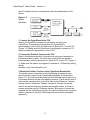
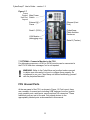
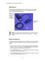
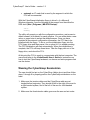
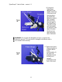
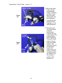
CyberGrasp v1.2 _________________________________________________________________________________________________ USER’S GUIDE Copyright © 2000-2003 Immersion Corporation All rights reserved. CyberGrasp™ User’s Guide – version 1.2 2 CyberGrasp™ User’s Guide – version 1.2 CyberGrasp™ User’s Guide v1.2 Immersion Corporation 801 Fox Lane San Jose, CA USA Phone: 408-350-8701 • Fax: 408-467-1901 www.immersion.com 3 CyberGrasp™ User’s Guide – version 1.2 CONTRIBUTORS Written by: Edited by: Hugo DesRosiers Daniel Gomez Jerry Tian Marc Tremblay Raymond Yu Rachel Miura TRADEMARKS VirtualHand and CyberGlove are registered trademarks of Virtual Technologies, Inc. CyberGrasp is a trademark of Virtual Technologies, Inc. Flock and Bird are trademarks of Ascension Technology Corp. Fastrak and Isotrak are registered trademarks of Polhemus, Inc. Windows NT is a registered trademark of Microsoft Corp. IRIX is a registered trademark of Silicon Graphics, Inc. Other product names mentioned in this manual may be trademarks or registered trademarks of their respective companies and are hereby acknowledged. ACKNOWLEDGEMENTS CyberGrasp was partially developed with funding from the Office of Naval Research’s STTR program (contract #N00014-97-C-0112). 4 CyberGrasp™ User’s Guide – version 1.2 Table of Contents Chapter 1 .............................................................................................................6 Getting Started .................................................................................................6 System Components........................................................................................6 Figure 1-1 ....................................................................................................7 Figure 1-2 ....................................................................................................8 Figure 1-3 ....................................................................................................8 Technical Specifications...................................................................................8 FCU..................................................................................................................9 Figure 1-4 ..................................................................................................10 Hardware Setup .............................................................................................10 FCU Orientation .............................................................................................10 Figure 1-5 ..................................................................................................11 Figure 1-6 ..................................................................................................12 Figure 1-7 ..................................................................................................13 FCU Unused Ports .........................................................................................13 Maintenance...................................................................................................14 Figure 1-8 ..................................................................................................14 Boot-up Sequence .........................................................................................14 Configuring the FCU for your Network ...........................................................15 Network Configuration Procedure ..................................................................15 Wearing the CyberGrasp Exoskeleton ...........................................................16 Figure 1-9 ..................................................................................................17 Figure 1-10 ................................................................................................17 Figure 1-11 ................................................................................................18 Figure 1-12 ................................................................................................18 Figure 1-13 ................................................................................................19 Figure 1-14 ................................................................................................19 Chapter 2 ...........................................................................................................21 FCU Software Installation ..............................................................................21 Full Installation Procedure..............................................................................21 Creating an Initialization Floppy .....................................................................22 Installing/Updating the CyberGrasp FCU Software Over the Network ...........23 Controlling the CyberGrasp Over the Network ...............................................23 Appendix A ........................................................................................................25 Troubleshooting .............................................................................................25 5 CyberGrasp™ User’s Guide – version 1.2 Chapter 1 Getting Started Congratulations on purchasing your new CyberGrasp™ haptic-feedback interface, a force-feedback option for Immersion Corporation’s CyberGlove® instrumented glove. With its intuitive “reach in and grab it” paradigm, this novel device provides a natural way to interface with complex 3D computer-generated worlds and to control end-effectors in telerobotic applications requiring a high level of dexterity. Possible applications include CAD, training and simulation, virtual reality, rapid prototyping, telerobotics, medical training, data visualization, education, and underwater exploration and salvage operations. This manual describes how to set up and get your CyberGrasp unit operational. Refer to the CyberGlove user’s manual for information on using the CyberGlove and to the VirtualHand® Suite User’s Guide and Programmer’s Guide for additional software information. The rest of this chapter explains how to set-up your system and wear the CyberGrasp exoskeleton. ! WARNING: If equipment is used in a manner not specified in this manual or by Immerison, the protection provided by the equipment may be impaired. System Components The CyberGrasp system, as shipped, should consist of the following parts. • • • • • • • • • Exoskeleton / Actuator Box (right : IV-RGRP-SA700 or left : IVRGRP-SA800) FCU : Force Controller Unit (IV-RFCU-SA700) Umbilical Cable (IV-RHAR708) AC Power Cable (Depends on country : CCABLE-IEC-XX) 3 Finger Ring Middle Small (IV-RMDA-SA719) 1 Finger Ring Pinky Small (IV-RMDA-SA717) 1 Finger Ring Thumb Small (IV-RTHB-SA719) Tracker adapter kit (IV-GSHP-SA110) Number 6 32 Nylon screws Number 4-40 Nylon screws Velcro Setup Floppy (CS-CYBERGRASP) 6 CyberGrasp™ User’s Guide – version 1.2 • CyberGrasp User Manual (CDOCS-GRASP) The CyberGrasp system components are shown in Figure 1-1. A 22sensor CyberGlove is the core of the interface, and is used to measure the joint angles of the fingers, hand and wrist. This information is used by the host to display a graphical hand on the screen or control a telerobotic manipulator. The CyberGlove is attached to a CyberGlove Instrumentation Unit (CGIU) which processes the CyberGlove data and communicates it to the CyberGrasp Force Control Unit (FCU). The exoskeleton is responsible for providing force feedback to the user. It attaches to the back of the hand and guides force-applying tendons to the user’s fingertips. The tension in the tendons is controlled by the actuators located in the actuator enclosure. A third party position tracker measures the position and orientation of the hand in space. The position tracker is attached to a tracker interface unit which processes the tracker data and communicates it to the FCU. Polhemus® and Ascension® electro-magnetic position trackers are currently supported and are required for most applications. They are not included as part of the CyberGrasp option and must be purchased separately. The FCU is the interface between the devices worn by the user and the host computers, which communicate with it via ethernet. The host computers need only communicate with the CyberGrasp FCU, which in turn communicates with all other peripherals (CyberGlove, position tracker and CyberGrasp actuators). Figure 1-1 CyberGrasp System Components The front panel of the FCU is shown in Figure 1-2. The red Actuator Power switch controls the power to their motors alone, without affecting the FCU processor. The actuator power indicator is lit when power is on. To reset the FCU (i.e. reboot), toggle the Processor Reset switch. The FCU Power switch controls power to the FCU’s central processing unit. The power to the motors will automatically be disengaged if the FCU Power is turned off. The Main Power switch located at the rear of the case (Figure 1-5) controls power to the whole FCU and, when turned off, overrides front panel switches. 7 CyberGrasp™ User’s Guide – version 1.2 ! NOTE: The Actuator Power switch light will flash intermittently upon shutoff, as the amplifiers for the motors power down. Figure 1-2 CyberGrasp FCU Circuit Diagram Figure 1-3 CyberGrasp Circuit Block Diagram Technical Specifications Performance Specification Force Description 12 N Max Continuous per finger 8 CyberGrasp™ User’s Guide – version 1.2 Environment For indoor use only. Intended to be used in laboratory/office environment. Specification Description Temperature +5 to +40 degrees C Altitude Up to 2000 m above sea level Humidity Max humidity 80% up to 31 degrees C, decreasing to 50% at 40 degrees C. Pollution Degree Equipment intended for use in pollution degree 2 environment. Electrical Specification Mains Description FCU US / Europe 100-240 VAC 60-50 Hz 13-7 Amps Mains supply voltage fluctuation not to exceed plus/minus 10%. Overvoltage Category II Protective Earthing Equipment is Class I Earthed equipment and must be connected to a properly grounded mains. Interface Ethernet (standard STP Category 5 Ethernet cable required) Mechanicals Specification Workspace Description 1 meter spherical radius from actuator module Weight 16 oz (Exoskeleton without CyberGlove) 44 lbs (FCU) 9 CyberGrasp™ User’s Guide – version 1.2 Figure 1-4 Force Control Unit Front Panel Layout Actuator Power Indicator Power Processor Reset FCU Power FCU Hardware Setup ! WARNING: Make sure the CyberGrasp Controller is powered-off when connecting the various components. The interfaces between the input/output devices, the host computer, and the CyberGrasp FCU are shown in Figure 1-3. The FCU communicates with the CyberGlove and position tracker via serial RS232 links. The actuators are controlled using an I/O card on the system bus. The host computer communicates with the CyberGrasp FCU via Ethernet. The following steps are required to connect all the devices: FCU Orientation It is recommended that the FCU be operated in vertical configuration only, as shown in Figure 1-2 Front Panel Layout. If the FCU must be operated in the horizontal configuration ensure that nothing is to be placed on top of 10 CyberGrasp™ User’s Guide – version 1.2 the FCU chassis as this could adversely affect the performance of the device. Figure 1-5 System Interfaces 1. Connect the CyberGlove to the FCU Refer to the CyberGlove manual for information on using your CyberGlove. The serial cord coming from the CyberGlove’s instrumentation Unit (CGIU) should connect to Serial Port 1 on the FCU (Figure 1-5). Make sure the CyberGlove is configured to operate at 115 kbaud by setting the dip switches on the CGIU. 2. Connect the Position Tracker to the FCU Refer to the tracker manual for information on using your Ascension or Polhemus position tracker. The serial cord coming from the tracker’s instrumentation unit should connect to Serial Port 2 on the FCU (Figure 15). Make sure the tracker is configured to operate at 115 kbaud by setting the dip switches on the instrumentation unit. 3. Mount the Position Tracker on the CyberGrasp Exoskeleton The tracker sensor is attached to the CyberGrasp exoskeleton via a mounting block located on the CyberGrasp backplate, as illustrated in Figure 1-4. The unit should be positioned such that the tracker cable runs in the same direction as the force-applying tendons. There are two sets of holes on the mounting block; one set is used for the Polhemus Trackers and the other for Ascension Trackers. Number 6-32 nylon screws are used to secure the Ascension trackers and smaller number 4-40 nylon screws should be used for Polhemus trackers. Both types of screws are supplied with the CyberGrasp system. As mentioned previously, a position tracker is required to use the CyberGrasp unit and must be purchased separately. 11 CyberGrasp™ User’s Guide – version 1.2 Figure 1-6 Mounting the Position Tracker ! NOTE: It is important to use nylon or plastic screws when fixing the electromagnetic position tracker to the backplate. Metal screws can distort the magnetic field and could adversely affect the accuracy of the sensor. 4. Connect the Actuator Enclosure to the FCU Connect the black cable that attaches to the actuator enclosure (Figure 16) to the back of the FCU (Figure 1-5). The actuator enclosure is the box that contains the motors that drive the tendons on the CyberGrasp exoskeleton. 5. Physically Connect the FCU to the Network Using a standard UTP Category 5 ethernet cable, connect the FCU to your network hub. The ethernet connector is located on the back panel of the FCU (Figure 1-5). The FCU can also be connected directly to the host computer if the proper ethernet cable is used. 6. Connect the Power Cord to the FCU Make sure the main power switch located on the back of the FCU is in the OFF position and verify that the voltage switch at the rear of the FCU is set to the proper voltage (115V or 220V). Connect the AC power cord to the back of the FCU (Figure 1-5). 12 CyberGrasp™ User’s Guide – version 1.2 Figure 1-7 Force Control Main Power Unit Port Switch Layout External AC Power Ethernet (Host Link) CyberGrasp Cable Actuator Enclosure Serial 1 (CGIU) VGA Monitor (debugging only) Serial 2 (Tracker) 7. OPTIONAL: Connect a Monitor to the FCU For debugging purposes, a VGA (or SVGA) monitor can be connected to the FCU to view error messages, but is not required. ! WARNING: Refer to the CyberGlove and position tracker manuals to obtain more information on how to configure them properly. Do not attempt to run your CyberGrasp unit before familiarizing yourself with the peripheral devices! FCU Unused Ports At the rear panel of the FCU, as shown in Figure 1-5 Port Layout, there are a number of unused ports including USB, keyboard, mouse, joystick ports, parallel ports, serial ports, sound card and I/O connectors. These additional ports are not to be used. Only attach devices to the appropriately labeled ports as documented in this manual. 13 CyberGrasp™ User’s Guide – version 1.2 Maintenance CyberGrasp is factory serviceable only, containing no user serviceable parts. Surfaces of Exoskeleton and FCU may be cleaned with mild detergent using a slightly damp cloth. Figure 1-8 CyberGrasp Actuator Unit and Exoskeleton CyberGrasp Cable ! NOTE: If you have an older CyberGrasp Force Control Unit, refer to its original manual for the port layout. CyberGrasp v1.1 - USER’S GUIDE Boot-up Sequence Once all the appropriate cables have been connected and the CyberGrasp is plugged in, the unit is ready for boot-up. The start-up procedure is as follows: 1. Make sure there is no disk in the floppy drive and that the FCU Power button is in the OFF (0) position. The FCU Power button is located on the front panel of the system controller (Figure 1-2). 2. Put the Main Power switch in the ON (I) position. The switch is located in the back of the controller (Figure 1-5). 3. Put the FCU Power switch in the ON (I) position. The switch is located in the front of the controller (Figure 1-2). 14 CyberGrasp™ User’s Guide – version 1.2 4. Wait for the FCU to boot up. When it is ready, it will emit three consecutive beeps. This will take approximately 30-40 seconds. 5. Turn on the CyberGlove and position tracker instrumentation units and wait approximately 10 seconds. At this point the FCU is ready to be configured for network operation. Configuring the FCU for your Network Communication with the CyberGrasp FCU is achieved via ethernet over a network. The FCU must therefore be added to your network just like any other new computer. If some of the terminology used in the following sections is unclear, please contact your system administrator. ! WARNING: A Microsoft Windows (NT/95/98) machine with a 1.44MB floppy drive is required for editing the FCU configuration floppy disk. Network Configuration Procedure The network settings for the FCU are configured by running the netcfg.exe utility provided on the CyberGrasp initialization floppy. This utility runs in a Microsoft Windows NT/95/98 environment. Before running the utility, you will need to obtain the following information from your system administrator: • host name: a name by which the FCU will be known within your network, • network domain: the name of your network domain (if any), • IP address: an IP address that is assigned to the FCU within your network, • network gateway: an IP address that refers to the network gateway for the network segment in which the FCU will be connected, • domain name server: an IP address for the computer that serves the domain names for your network, 15 CyberGrasp™ User’s Guide – version 1.2 • netmask: an IP mask that is used by the segment in which the FCU will be connected. With the CyberGrasp initialization floppy in drive A: of a Microsoft Windows computer, type the following at the prompt from the within the DOS shell (Start | Programs | MS-DOS Prompt): cd a: netcfg The utility will prompt you with the configuration questions, and present a default answer (in brackets) for each question. You can either enter a new value, or press enter to accept the default answer. Once you have provided all the network configuration information, the FCU has to be initialized with the floppy. To do so, put the initialization floppy into the FCU floppy drive and then power it on or reboot it if it is already working. The FCU initialization will start automatically. When the initialization is complete, the FCU will beep three times. Take the floppy disk out of the floppy drive, and reboot the FCU. At this point the FCU is ready to communicate with the host computer. The user should refer to the VirtualHand® User’s Guide for instructions on how to test the CyberGrasp hardware, run demos and write programs that use the device. Wearing the CyberGrasp Exoskeleton The user should first put on the CyberGlove (fabric glove) and then follow steps 1 through 8 to properly position the CyberGrasp exoskeleton on the hand: 1. Make sure the tendon cables and the CyberGlove cable are not tangled before beginning. They should all fall to the right of the arm for a right-handed system, and to the left of the arm for a left-handed system. 2. Make sure the thumb tendon cable goes over the arm and not under. 16 CyberGrasp™ User’s Guide – version 1.2 3. Position the CyberGrasp backplate in the middle of the back of the hand such that the plate is just behind the abduction sensors (the U-shaped elements rising from the back of the CyberGlove). The plate should rest comfortably on the back of the hand. All cables should go over and to the pinky side of the hand. Figure 1-9 ! WARNING: Do not place the backplate on top of, or against, the abduction sensors! This may result in damage to the sensors and is not covered under warranty. 4. Tighten both Velcro straps as tightly as possible without being uncomfortable. At this point, the backplate should be firmly an d squarely positioned on the back of the hand. Figure 1-10 17 CyberGrasp™ User’s Guide – version 1.2 Figure 1-11 5. Slide all the finger loops onto the corresponding fingers. If they are too tight, loosen them using the thumbscrew. The force applicator rings should then be slid onto the fingertips, i.e. the distal phalanges. Figure 1-12 6. The finger loops can be tightened using the thumbscrews. Position the cam in the center of the middle phalanx before tightening. Flexing the finger makes it easy to locate the middle phalanx. The device comes with multiple finger rings. If the current ring is too small or too large to reliably stay on the fingertip, use the ring clip to replace it with another one. 18 CyberGrasp™ User’s Guide – version 1.2 ! Figure 1-13 7. The next step is to ensure that the thumb assembly is properly aligned with the thumb as indicated in the Figure 1-14. This is achieved with the adjustment screw shown in Figure 1-19. Figure 1-14 8. When the adjustment screw is loosened, it is possible to slide the thumb assembly back and forth in the slots. The slots are designed such the orientation of the assembly does not change as it slides through the slots. When moving the assembly, hold on to the adjustment screw, not the assembly itself, as it may bind. Very little torque is required to sufficiently tighten the screw. Excessive torque may cause damage. WARNING: Do not place the backplate on top of, or against, the abduction sensors! This may result in damage to the sensors and is not covered under warranty! 19 CyberGrasp™ User’s Guide – version 1.2 20 CyberGrasp™ User’s Guide – version 1.2 Chapter 2 FCU Software Installation The CyberGrasp Force Control Unit (FCU) comes with a Device Manager and all associated software pre-installed at the factory. In normal situations, it must only be given a network name and address, so that it can operate over a TCP/IP network. This procedure is explained in Chapter 1 - Getting Started. If for any reason the FCU software should become damaged, the VHS 2000 distribution CD contains all necessary files for initializing and configuring the FCU. Refer to the Full Installation Procedure section for instructions on a complete installation of the FCU from scratch. ! WARNING: Reinstalling the FCU software is not required on new units! Only refer to this chapter if upgrading the FCU software or reinstalling it to replace lost/damaged files. Full Installation Procedure A full software reinstallation of the CyberGrasp Force Control Unit can be required to upgrade or downgrade the control software, or in the case of a hardware failure of the internal hard disk of the FCU. The following sections describe the procedure to re-create a minimal installation floppy disk, and then make a networked-based installation of the control software on the FCU. ! NOTE: For a full installation, a networked computer (running Microsoft Windows NT/9x, IRIX or Linux) is required for installing the CyberGrasp FCU Software over the network. All files are stored in a directory named FCUInstallation. The installation software is available for Microsoft Windows NT/9x, SGI Irix 6.4 & 6.5 and Linux, in the winnt_386, irix_mips and lnx_386 directories respectively. A full software installation procedure begins with the creation of a minimal installation floppy disk for the CyberGrasp FCU. It is then followed by a 21 CyberGrasp™ User’s Guide – version 1.2 remote full installation of the FCU, once the CyberGrasp unit has booted from the floppy. Creating an Initialization Floppy This process consists of transferring a disk image onto a floppy disk. The disk image is located in the FCUInstallation/boot_floppy directory of the distribution CD. • Put a blank formatted floppy into the floppy drive of a Microsoft Windows computer. • Open a DOS shell, and go the to FCUInstallation/boot_floppy. To open a DOS shell, click the Windows Start button on the bottom left corner of your screen. Go to the Programs pull-out and then click on the MS-DOS Prompt icon. • Finally, type the line below and follow the instructions: rawrite -f cgrasp.raw -d a The floppy drive will be active for approximately 30-45 seconds. ! ! NOTE: You will require the same information than that required in Chapter 1 in the section on Configurating the FCU for your network. Please consult your system administrator to obtain this information. WARNING: Once the disk image has been copied to the floppy disk, label it carefully. BOOTING YOUR COMPUTER WITH THAT FLOPPY DISK MAY RESULT IN UNRECOVERABLE DATA LOSS AS THE CYBERGRASP SOFTWARE REPLACES THE CONTENTS ON YOUR MAIN DISK! Once the initial installation has succeeded, the FCU will beep once every 10 seconds to indicate that it is awaiting the rest of the Device Manager software to be installed over the network 22 CyberGrasp™ User’s Guide – version 1.2 Installing/Updating the CyberGrasp FCU Software Over the Network This process consist of transferring the software packages from your workstation to the CyberGrasp FCU, using the network link. The software packages are contained in a single archive, located in the FCUInstallation/<OS_ARCHITECTURE> directory of the distribution CD. For example, if you are using Microsoft Windows NT/9x, you will find the archive in the FCUInstallation/winnt_386 directory. From a command prompt (DOS or Unix), go to the appropriate directory, and type: update_grasp.bat numeric_ip_address_of_grasp (on MS Windows 9x/NT) update_grasp.sh numeric_ip_address_of_grasp (on Unix) The numeric_ip_address_of_grasp is the number you provided at the configuration stage of the initialization floppy disk. Depending on your network capacity and traffic, the data transfer will take from one to ten seconds. The FCU will beep three times after the software packages have successfully been installed. At that point, a Device Manager is started automatically and is ready to handle client requests. You can use either the Device Control Utility or the demo applications supplied in the distribution CD to insure that the CyberGrasp is working properly. Please refer to the VHS User’s Guide for doing so. Controlling the CyberGrasp Over the Network The CyberGrasp controller can be controlled and monitored over the network for maximum flexibility. The FCUInstallation/<OS_ARCHITECTURE> directory of the distribution CD contains a shell-based utility called nc, that will let you perform remote management. To use it, you must go to the appropriate directory, and type: nc numeric_ip_address_of_grasp 24 The following menu will appear on the screen: ====================================================== a. restart the device manager b. restart the device manager and watch its output c. reboot the grasp controller 23 CyberGrasp™ User’s Guide – version 1.2 d. shutdown the grasp controller q. quit ====================================================== Type your choice and hit <enter>. You can choose any above menu items by type its leading character and hit the enter key. 24 CyberGrasp™ User’s Guide – version 1.2 Appendix A Troubleshooting If you are experiencing problems with your CyberGrasp unit, please read the following list of problems carefully. If you are still unable to solve your problem, you can contact Immersion Corporation support staff at [email protected] PROBLEM: Cannot hear the three beeps after the floppy drive light goes off. SOLUTION: This is most likely caused by a defective boot floppy. Try to make another boot floppy, preferably using a new diskette, and boot the GyberGrasp with it. If it still fails, try to make the floppy on another machine. PROBLEM: The update_grasp.sh on NT or update_grasp.sh on Irix prompts “Failed to connect to the CyberGrasp”. SOLUTION: The message indicates that the installation program cannot establish a stable connection to the FCU. The following should be checked: • Make sure the network setting for the FCU is configured properly, and has access to your LAN. Any typographic error in the information you provided when running netcfg.exe will likely cause the FCU network interface be configured incorrectly. Examine the settings by running netcfg.exe on the boot floppy again. Contact your network administrator if you are not sure about the settings. • Make sure the host computer can access the FCU over the network. This can be verified by using the ping command and “pinging” the FCU from the host machine as: ping grasp_ip. • Only one update session is allowed to run at any time. Attempts to start the update process will be denied if there is another update session running. I you aborted an update; please wait for at least 10 seconds before another attempt. 25 CyberGrasp™ User’s Guide – version 1.2 PROBLEM: I could not hear the three beeps after the installation program finished on the host computer. SOLUTION: Your network may be experiencing heavy traffic at the moment you run the update program. Therefore it may time-out before it finishes the update. Try to run the update program a few more times. Also, the beeps may be too weak to hear if you are at a distance from the FCU. Verify whether the Device Manager is running with the Device Control Utility. You can also use the nc program to restart the Device Manager or reboot the FCU manually. PROBLEM: The FCU beeps continuously after it is booted with the Installation floppy. SOLUTION: The beeps is normally an indication of serious hardware problem. Please contact Immersion technical support for further assistance. PROBLEM: The software installation finished successfully, but I could not access the FCU with the nc utility. SOLUTION: Reboot the FCU. PROBLEM: I can control the CyberGrasp with nc, but my application fails to access devices on it. SOLUTION: Make sure you can access the FCU with the Device Configuration Utility (See VHS User's Guide for more information). • Make sure the right IP address is being used by your application. If a canonical address (e.g. grasp.domain.com) doesn't work, try the corresponding numerical IP address (e.g. 192.1.34.15) instead. • Make sure the configuration of the device matches what is specified in your application. Check if it is connected to the right serial port, running at appropriate baud rate etc. You may choose to restart the Device Manager and watch its output in the nc program. This will give you more clues as you debug the setup. 26