1
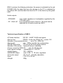
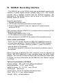
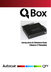
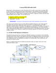
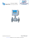
Complex protection against eavesdropping
Enhanced application of MRA-3Q
Object System QM4000
Bus Interface QMI-2
Audio recording adapter SCAN-R
user manual
Read this manual before use
Version Q1.2
I. Object network system QM4000
QM4000 is an advanced network system for complex protection of an
object against eavesdropping. The system allows parallel connection of
up to 32 MRA-3Q radio analyzers using a dedicated object network.
QM4000 allows full remote control of each device, and supports
numerous additional features like spectrum analysis in the range of 36 3600 MHz, background statistic, new signal statistic, automatic audio
sampling, frequency and spectrum records, selective statistic, system
statistic, etc. All these features are easily accessible from the QMaster
software - a user friendly control application with graphical user interface.
QM4000 is not only a comprehensive solution for object permanent
protection, but also a very effective tool for specialists since it gives a
clear graphical picture of the current RF signals. QM4000 allows to
detect and record even such dangerous systems like spread spectrum,
or modified WiFi, DECT and GSM.
1. Minimal HW configuration
- CPU:
Pentium III 500 MHz and higher
- Memory: 128 MB RAM
- Interface: - Free serial port RS232
- Audio input / output supported by the operating system
- Display resolution: min. 1024 x 768 pixels
- Operating system: Windows 2000, Windows XP
(Windows 98 and NT can work, but are not officially
supported)
- EMC/EMI parameters:
The latest desk top PCs and notebooks are usually fulfilling tough
spurious radiation limits and do not alter spectrum analysis results. Some
older or no-name PCs can cause parasite peaks in the frequency
spectrum. The critical point can be the AUDIO input or the USB interface,
especially if the USB/RS232 converter is used.
Detection of low quality PC parasite radiation:
a) Connect the PC with QMI-2 and MRA-3Q using the purchased cables
b) Switch OFF the PC
c) Manually execute the "Spectrum Entry" instruction on the MRA-3Q
d) Set SCAN mode on the MRA-3Q
2
e) Switch ON the PC and start QMaster. If pre-alarms appear on the
MRA-3Q after switching ON the PC check the new signals. Verify if
the real interfering signal source is the PC.
f) The best spurious radiation test is a spectrum analysis done in a radio
signal free area, e.g. a deep cellar with no electronic equipment.
2. SW installation
- Insert the QMaster CD into the PC
- Select language "Cestina=Czech or English"
- Follow the Setup Wizard, do not forget to read and accept the License
Agreement!
- In "Select Components" window select:
"Documentation" to install all detailed user manuals and specifications
"Example Data" to enable demonstration of the QM4000 functions
without having the real devices (QMI, MRA-3Q)
- The QMaster icon appears on the screen after successful installation
3. Running the program and Setting Parameters
3.1. Start the program click on the QMaster desktop icon or using the
Windows Start Menu. Find QMaster folder and select the QMaster icon
there.
3.2. Connect the QMI-2 interface (see QMI-2 user manual) and at least
one MRA-3Q device. The MRA-3Q has to be switched ON and set to
"SCAN" or "Autom.tuning" mode. If the MRA-3Q is in any other mode the
QMaster can not either control or read the data from the device. The
QMI-2 has to be powered by 12V DC (any adapter 12-20V DC or a
battery).
3.3. In the main menu File select Preferences...
-Serial port setting: check if the selected port number matches the port
where the QMI-2 is connected (default COM1). The real COM number
depends on HW configuration of the PC. The USB/RS232 converters
usually have a higher port numbers. To find the corresponding COM set
COM1 to COM9 successively and always confirm by "OK". To speed up
this process you can manually set the device ID number by using the
"Add" button. After COM port selection press the Scan Bus button in the
QMaster window. If QMaster finds the connected device the system is
3
ready for use. Otherwise select a different port and repeat the process. If
all ports were tested and the communication always failed check the
cables, the state of the device and settings of serial ports in Windows.
A green text or green "OK" in the communication window indicates the
start of QMaster - device communication.
- Default update period (default 30 sec) is a period of data collection
from all connected devices
- Current device update period (default 10 sec) is a period of data
collection from the selected device which is displayed in the right part
of the screen.
If "Record Audio" is enabled:
- Audio record length (default 10 sec) is an audio sample length of the
signal which caused an alarm.
- Audio record period (default 2 min) is the minimal time between any
audio samples from the same device. After this time another audio
sample will be recorded from the same device, but from the different
frequency channel if more frequency channels are in alarm status at the
same time.
- Audio re-record period (default 10 min) after this time a repeated
audio sample will be recorded from the same device and from the same
frequency channel
Confirm required settings by "OK" button
4. Working with the connected device
- Click on the device line in "Devices" section to open dialog window in
the right part of the screen.
- Set the cursor over required button or information. A help text line (tool
tip) appears to explain the function.
- Left mouse button allows to select items from various lists (e.g. device
list or alarms). Multiple item selection can be made by holding the left
mouse button and moving the mouse cursor over multiple items.
Alternatively the multiple selection can be made using Ctrl button
together with mouse clicks. A double click activates tuning to
corresponding frequency (in frequency based windows only).
- Right mouse button selects a region for zooming in the background,
spectrum and history windows.
4
5. Spectrum analysis, spectrum display
Main menu item "Device" offers: - Load spectrum
- Show spectrum
- Load spectrum offers choice of all spectrum records stored as files on
the disk (∗.fsg)
Note: It is very useful to save the spectrum analyses records for future
comparison or like a reference. Add suitable name to the file (place, time,
situation etc.). By default QMaster saves the last analysis to freq.fsg file.
- Show spectrum is displaying the last spectrum selected from the
memory or the last spectrum analyses result.
6. Help, user manuals, dialog windows
- The basic user information are available in the main menu:
"Help" - Contents F1
- The help text line (tool tip) always appears when the cursor stops over
a button or over a function window for a while.
- The detail user manual with dialog windows is available in the Start
menu.
Set: Start menu | Programs | QMaster | Documentation | QMaster
Manual CZ or EN (CZ = Czech, EN = English)
- Other documentation and specifications (MRA-3Q, QMI etc.)
Set: Start menu | Programs | QMaster | Documentation | Other |
DOWNLOADS select required document in Czech or English
7. QMaster DEMO
The DEMO option of QMaster works without limitation for first 10 days.
After 10 days the program is running 5 minutes only and the spectrum
analysis works only to 110 MHz instead of 3600 MHz.
5
II. Bus interface QMI-2
QMI-2 serves to connect a master PC to the QM-4000 system. The PC is
connected to QMI-2 via a D-sub 9 connector (RS-232) and a 3.5mm
audio jack. The QM-4000 bus is connected to another D-sub 9 labeled
DEVICE BUS on QMI-2.
The bus carries the following signals:
1) Supply voltage for MRA-3Q devices, 12–17V
2) RS485 signal pair with proprietary data protocol
3) Audio line (switched on selectively by MRA-3Q)
Layout of the device bus (QMI/MRA cable):
CAN 9 pin
Wire color
Signal
MRA-3Q
------------------------------------------------------------------------------------------------1
yellow
AUDIO
OPTIONS middle
2
gray
GND
CHARGER 3
white
GND
CHARGER 4
red
+14 V
CHARGER +
5
NC
6
shield
GND
CHARGER 7
green
RS485 OPTIONS right channel
8
orange
RS485 +
OPTIONS left channel
9
NC
When extending the bus the following wires should be paired:
audio
power
RS485
1 and 2
3 and 4
7 and 8
A non-stabilized DC adapter 12V / 0.3-1A shall be connected to the
POWER connector (the maximum current depends on the number of
devices on the bus). The bus can be as much as 1200m long, wired from
one device to another. If the bus is longer than 20m it is necessary to
use a termination resistor at the most distant device (120 ohm
connected between the green and the orange line, i.e. RS485+ and
RS485-). The RS232 cable used for connection of QMI-2 to the PC
should not be longer than 8m. The length of the audio cable to the PC
(3.5mm jack) is not critical.
6
QMI-2 contains the following indicators: the power is indicated by the red
POWER LED, the data flow from the devices to the PC is indicated by
the yellow LED, and the data flow from the PC to the device by the green
LED.
Audio outputs:
- SPEAKER
- PC 50mV eff
max. 0.5W, earphone or loudspeaker regulated by the
VOLUME knob.
for a microphone input of the PC. The level can be
adjusted by a trimmer inside the QMI-2
Technical specification of QMI-2:
•PC data interface
RS 232 (UART 16550 and higher)
•Device bus
RS485 + audio line 300mV eff + power 12V
•Number of connected devices
up to 32 x MRA-3Q
•Bus length
max. 1200m, parallel, line configuration
•RS485 termination
120 ohm at the most distant device
•Number of bus wires 3 pairs (6 wires) + shielding
•Power current for MRA-3Q
max 1A (32 devices)
•Input power voltage
unstabilized 12 - 20V DC
•Audio filtering
300 - 3400 Hz
•SPEAKER output
max. 0.5W 4 - 32 ohm, regulated
•PC audio output
50 mV eff, internally adjustable
•Size
115 x 70 x 32 mm
•Weight
300g
7
III. SCAN-R Recording interface
The MRA-3Q set to the SCANr mode can automatically record audio
samples of alarm signals without actually using a PC. This function
requires only a suitable recorder and the SCAN-R interface. The
description of the SCANr function can be found in the MRA-3Q User
Manual, section XI. SCANr.
Recorder specification:
1. External microphone input
2. VOX function (recording activation by audio signal)
3. Power supply suitable for long-term operation or external power
connector 3V DC
The recording interface SCAN-R is a compact device consisting of the
following components:
- Power supply adapter 230V / 0.3A
- 3 V DC stabilizer for an audio recorder
- Audio converter of the MRA-3Q line output to the microphone level
Input / output connectors:
- 5.5/2.1 mm 12 V power. Connect to MRA-3Q CHARGER connector
- 3.5 mm stereo connector. Connect to MRA-3Q OPTIONS connector
- 2.5/0.7 mm 3 V DC power connector (middle = + pole). Connect to
external power of the recorder
- 3.5 mm mono connector. Connect to the external microphone input of
the recorder
Before long-term monitoring the VOX sensitivity must be adjusted as
follows: Set VOX sensitivity to start recording when the audio signal
appears. The VOX has to stop recording when the MRA-3Q returns back
to SCANr. For more information see the MRA-3Q User Manual, section
XI. SCANr.
Technical specification of SCAN-R
•Power voltage 220 - 240 V AC (EN proved adapter)
•Recorder power 3 V DC max 150 mA
•MRA-3Q power 12 - 17 V DC max 150 mA
•Audio input 300 mV eff
•Audio output 20 mV for recorder microphone input
•Size 55 x 13 x 11 mm without adapter
•Weight 290 g including adapter
8