1
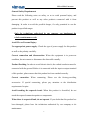
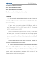
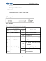
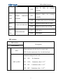
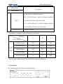
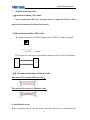
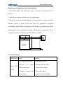
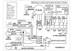
2E1 to 2Eth Converter
2E1-2ETH Converter
User Manual
Winyuan Technology Co., Ltd
(Http://www.winyuan.com)
1
2E1 to 2Eth Converter
Preface
Data communication standard is agreed on, published and abided by in order to
accomplish communication among the different units from different vendors. But
different communication networks have different standards due to their
development periods, background and other historical reasons. For example, G703,
V.35, X.21, V.36, RS-422 and RS-530 are all used in high-speed communication
with little functional difference. But they differ in their physical and electrical
characteristics. Multiple existing standards inhibit their direct communication as to
need a media between different products. Our conversion products are designed to
meet the above requirements. For the application, convertible forms are available
as follows:
Electrical: Converting the signal levels;
Physical: Providing a different connector type
Functional: Converting the functional operation of the signals
Rate: Converting from one data rate to another.
2
2E1 to 2Eth Converter
Contents
PREFACE....................................................................................................1
GENERAL SAFETY REQUIREMENTS..................................................4
OPERATING MANUAL............................................................................6
1.FUNCTION
6
2.FEATURES
7
3.SPECIFICATION
8
4.FRONT PANEL
10
.LED indicators .................................................................................. 10
DIP SWITCHES
11
5.REAR PANEL
13
Power supply....................................................................................... 14
E1 interface ........................................................................................ 14
ETH interface: ................................................................................. 14
6. B OTTOM PANEL
15
7.TO MAKE LINES
16
8. INSTALLATION
16
To check appearance .......................................................................... 17
Installation ......................................................................................... 17
9.TROUBLESHOOTING
18
10. TYPICAL APPLICATION
20
3
2E1 to 2Eth Converter
General Safety Requirements
Please read the following notes on safety, so as to avoid personal injury, and
prevent this product as well as any other products connected with it from
damaging. In order to avoid the possible danger, it’s only permitted to use the
product in specified ranges.
Only the technicians authorized by our company can implement the
relative maintenance work.
Avoid Fire or Personal Injury.
Use appropriate power supply. Check the type of power supply for this product
as well as the polarity carefully.
Correct connection and disconnection. When the equipment is in power-on
condition, do not connect or disconnect the data cable casually.
Product Earthing. In order to avoid electric shock, the earthed conductor must be
connected with the ground. Before it is connected with the input or output terminal
of this product, please ensure that this product has been earthed correctly.
Correct connection. When connecting, Please use the factory-providing
accessories. If special connecting, please pay attention to the distribution
requirements for pins.
Avoid touching the exposed circuit. When this product is electrified, do not
touch the exposed connection points or components.
When there is suspected fault, do not operate. If you doubt that this product has
been damaged, please have the technicians authorized by our company to do
maintenance.
4
2E1 to 2Eth Converter
Provide sound ventilation environment.
Do not operate in humid environment.
Do not operate in explosive environment.
Please keep the surface of this product clean and dry.
Quick guide
2E1- 2Eth converts E1 signal and Ethernet signal to each other. There are five
work modes for Ethernet interface. And E1 interface is with 75Ωor 120Ω. Please
indicate when ordering.
1) Connect proper power supply according to POWER mark on the rear
panel. When needing DC–48V, set AC/DC switch to DC-48V. When needing
AC220V, set AC/DC switch to AC220V.
2) Select the needed branch of physical interface according to E1 line. When
the sending signal E1 interface is connected with the receiving signal E1
interface, there would be no E1 alarm. If there be, please check the fault by E1
loop.
3) Ensure Ethernet interfaces status without E1 line fault. There are five
work mode of Ethernet interface for user to select.
4) when 2E1-2Eth converter connected, LINK indicator will light normally.
While whether F/D and SPD indicators are ON or not depends on the setting
mode of Ethernet working status. If Link indicator is not ON, please check
whether cable is made according to requirement. (SW5 must be off) Two
Ethernet interfaces can be freely used if needed.
5
2E1 to 2Eth Converter
Without special requirement, users can operate 2E1 to 2Eth converter
according to factory setting
5)
Ethernet interface is cross cable and direct connecting cable
auto-negotiation. User can select either cross connecting cable or direct
connecting cable.
6) When working normally, PWR and LINK indicators are both ON.
Whether F/D and SPD indicators are ON or OFF depends on the setting mode of
Ethernet working status. The other LED indicators are all OFF.
7)Without special requirement, it can work normally with Sw1-4,SW6-8
on and the others off.
8)If the unit still can work normally according to the above operating and
the manual, please contact with your supplier and technicians.
Operating manual
1.Function
①
Converts signals between E1 interface and G.703 interface.
②
a self-learning remote Ethernet Bridge with high performance. Apply to
those bridging whose cost is sensitive and can be stretcher and breaker for LAN
basic on bite stream. The unit can continuously learn MAC destination address of
the connected LAN and determine whether frames can be forwarded or filtered
6
2E1 to 2Eth Converter
according to MAC destination address of data frames
③
Transmits Ethernet MAC fame data through E1 channels (channel 1 to
channel 2) by point to point. Max. E1 transmission rate can be up to 7.936 Mbps.
④
Supports SNMP.
2.Features
1. E1 channels (from channel 1 to channel 2) are used to transparently transmit
Ethernet data at 10M/100M.
2. Have build-in SDRAM controller with capacity of 1MX 16Bits.
3. When Ethernet data transmitted, the frames are reordered in the E1 channel so
as to assure frame’s order effectively and improve the transmission rate.
4. It allows that the Max. Transmission time difference of frames’ order between
each two E1 channels can be 32 ms, which can assure be used stably and reliably
in each complicated network.
5. When Ethernet data transmitted, bandwidth attenuation of every E1 channel is
only 64Kbps. And the actual effective bandwidth is 1.984Mbps.
6. Automatically check the used E1 channel numbers and automatically assign
bandwidth.
Supports limitation setting of CRC error code. When error code rate is beyond
the limitation, the system can automatically isolate the E1 link.
7. Abundant alarm functions of LED indicator are for fast diagnostics
8.When the units works normally, Plug and play any E1 line,will not influence
the units.
7
2E1 to 2Eth Converter
9.Local loop function available ( Four E1 channels are looped together)
10. Support CRC error limitation function.
11. When error code over E1 transmission direction is beyond limitation, only E1
transmission direction is isolated. It has no impact on the other direction.
Asymmetry is materialized in process of Ethernet transmission to assure the Max.
Data transmission rate with E1 fault.
12.When a receiving direction of any E1 link
Receives LOS, AIS and LOF alarms, the corresponding send direction will not
be influenced so that Asymmetry transmission is materialized over E1 link.
13.when all the receiving directions of E1 links are cut off and isolated, local
alarm and SNMP information can still be transmitted to the remote endpoint
through sending direction of E1 link. Uni-direction transmission is
materialized over E1 link. The Function is especially suitable for associated
operating between protocol converters and optical equipments. It is used to
diagnose fiber failure when the uni-direction fiber of optical equipment is shut
off.
3.Specification
1. G.703 interface
*
rate:
*
Code type:
*
*
n *(2.048Mbit/s±50ppm) (N=1~2)
Impedance:
HDB3
75Ωunbalanced/120Ωbalanced
Interface standard: Meets G.703and G.704standards
8
2E1 to 2Eth Converter
*
Connector:
Q9 (75Ω),RJ48-C(120Ω)
Must used in pair.
2. Ethernet interface
² Standard MII interface. Meets IEEE802.3 standard Two Ethernet interface
with switching function can save a SWITCH for users.
² Supports flow control of full duplex PAUSE
² No. of Ethernet interface:
Two
² Requirement for making lines:Cross cable and direct connecting cable
auto-negotiation.
3.Voltage:
Desktop: AC 220V, DC -48V Compatible
Rack: AC 220V or DC -48V with heat backup function.
4. Fluctuant voltage
180 VAC ~ 260 VAC
or -38 VDC ~ - 72 VDC
5.Power consumption:< 5W (desktop)
< 75W (rack)
6. Operating condition
Temperature
-20℃ ~ +70℃
Humidity
95%
Atmospheric pressure 70Kpa ~ 106Kpa
Non-corrosion and non-solvent gas
9
2E1 to 2Eth Converter
Non-dust
Non-magnetic field interference.
7. Dimension
Dimension for desktop 218mm*136mm*44mm
4.Front panel
.LED indicators
There are eleven LED indicators on the front panel.
LED indicators
Working status
Name
PWR
Function
POWER indication
Status
ON
PWR is working normally
OFF
PWER is OFF
Two E1 connection
E1 interface has received AIS
on
AIS1~AI
indication
alarm
S2
E1 interface have not received
off
AIS alarm.
E1Los1
Alarm for E1 signal
~
loss
ON
Alarming for E1 signal loss
Alarming
for
twinkling
E1Los2
desynchronizing
10
E1
framing
2E1 to 2Eth Converter
Four
E1
links
are
working
are
working
OFF
normally
Ethernet
Link1 ~ Ethernet
connection
links
ON
normally
Link2
indication
OFF
No other units access to our units
ON
Ethernet works at rate of 100M
SPD2
OFF
Ethernet works at rate of 10M
F/D1 ~
ON
Full duplex
OFF
Half duplex
SPD1 ~
Ethernet rate indication
Duplex indication
F/D2
DIP switches
DIP switches
Description
Serial number
Alarm indication for the local or remote unit
S1
SW1
OFF--For the remote unit, On—for the local unit
limitation setting of error code
SW2 to SW3
ON, ON --
No limitation
ON, OFF--
Limitation value:1×10 -4;
OFF,ON --
Limitation value :1×10 -5;
OFF,OFF -- Limitation value :1×10⁻⁶。
11
2E1 to 2Eth Converter
DIP switches
Description
Serial number
For the local E1 loop
OFF--Loop;ON—NO loop
SW4
When testing loop function, pls cut off Ethernet firstly
in case of broadcast storm.
Setting off, On to work normally
SW5 to SW6
If needing to change Ethernet work mode and VLAN,
please switch SW5 to on first and then to Off.
SW7
For new reversion
SW8
For new reversion
Setting for Ethernet duplex
S2
SW9
OFF—Full duplex;ON—half duplex
Ethernet rate
SW10
ON--10M;OFF--100M
Auto-negotiation function for Ethernet
SW11
Then Sw9 and Sw10 ineffective
OFF—Can auto-negotiation;ON- no
12
2E1 to 2Eth Converter
DIP switches
Description
Serial number
VLAN setting fro Ethernet interface
OFF—VLAN effective,and two Ethernet interfaces
are isolated and can’t access each other.
SW12
ON—VLAN ineffective,and Two Ethernet interface
are switchable ,and can access each other.
SW13to SW16
For new reversion
Attachment: Comparison table of Ethernet work modes
SWITCH
9
10
11
100Mfull duplex
OFF
OFF
ON
100Mhalf duplex
ON
OFF
ON
10Mfull duplex
OFF
ON
ON
10Mhalf duplex
ON
ON
ON
Auto-negotiation
X
X
OFF
FUNCTION
MODE
SEL
Note: X can be either ON or OFF, ON effective and OFF ineffective.
5.Rear panel
1) E1 interface with 75Ω. The rear panel as follows:
13
2E1 to 2Eth Converter
2) E1 interface with 120Ω.The rear panel as follows:
Power supply
Power supply has Ac220V/DC-48 compatible which can be selected by the
users.
If the user need -48V , Set AC/DC switch to “DC-48V”.If the user need 220V,
Set AC/DC switch to “AC220V”.
When power supply is –48V, positive polarity of unit should be connected
with positive polarity of the power supply in the room. And so does the negative
polarity.
E1 interface
Users can select the line according to requirement.
E1 line with 75Ω: Offer two interfaces with impedance of 75Ω.
E1 line with 120Ω:Provides four E1 interfaces with 120Ωfor user to select.
ETH interface:
Ethernet interface is a standard MII interface. Two Eth interfaces are available on
the rear panel. Cross and direct connection cable auto-negotiation for Ethernet
interface.
Supports flow control of full duplex PAUSE. Pins of Ethernet interface
are 1, 2,3 and 6。
14
2E1 to 2Eth Converter
Note : When Ethernet cable at the Eth interface is longer, two pins of
receiving signal must be connected to one UTP and two pins of sending signal
are connected to one UTP.
6. Bottom panel
2 DIP switches
ON --indicating E1 signal is grounded
OFF—indicating E1 signal is not grounded
SW1: receiving signal grounded
SW2: sending signal grounded
Notice: On the whole E1 link, assure only one termination is grounded.
The rack device has these two switched on the back of casette side.
Hanging function (optional)
If needing hanging function, please indicate in order list.
15
2E1 to 2Eth Converter
7. Method of making cables
(1)method of making 75Ω cables:
Core is connected with core, out layer sheet is connected with out layer
and core is disconnected with out layer sheet.
(2)The method of making 120Ω cables:
The physical interface is RJ48-C(Marked with “RJ48-C”On the rear panel)
1,2,3,4,5,6,7,8
4, 5 Out, 1,2input
IF the units are used in pair, the method of making a line is shown as follows:
1
4
2
5
4
1
5
2
RJ
48
RJ
48
(2)The method of making an Ethernet cable
The method for straight Ethernet cable:
The method for cross-over Ethernet cable
8. Installation Process
Before operation, please read the notice carefully, and pay more attention to the
16
2E1 to 2Eth Converter
marked.
Such marks as “note”, “warning” in operation manual are specially remarked on
how to operate safely and correctly, which should be observed strictly.
Packing and appearance checking
1) After you receive devices, firstly you should check whether the packing is
damaged, if it is, please contact with our after-service department immediately
so as to solve the problem in time.
2)
Please check according to the loading list with the box open. If there is
damage on the outside of rack, please contact with installation person or
after-service department directly so as to exchange.
Installation
1) Fasten the equipment in the rack-Mounted.
2)Input the power, If it is DC input, First measure its voltage value and its polarity
with multi meter, our device will self- detect automatically while you can detect
whether the indication lights work normally.
3)Sending signal and receiving signal over E1 interface should corresponding.
Equipment Maintenance
1) Before leaving the factory, the equipments have been adjusted at their best. And
all the functional interfaces are located in the front and rear panel. So do not open
the equipment by yourself without our technicians.
2) When the equipment encountered with troubles, you can check the trouble area
range by single self-loop function and contact with our company in time.
17
2E1 to 2Eth Converter
Requirement for apparatus room and grounding
1) It should be placed in a stable place where is convenient for personnel to test
and set.
2) Ambient environment should be dry, tidy and draughty.
3) During the installation and maintenance of the equipment, necessary anti-static
measures should be taken, so the rack should be grounded to strengthen
anti-jamming ability and prevent lighting strike. Working and protection ground of
independent erection should be available and ensures to grounded well for
equipment operation. Connecting method is shown as follows:
GND
GND
-48V
OMT-E06C
机
GND
-48 V
开
关
电
源
OMT-E06C
架
防 静 电 地 板
9. Trouble shooting
Phenomenon causes
solutions
1.Not completely pressed
2.Incorrect
in
1.Completely pressed
Power 2.Exchange their polarities
Power LED
polarity connection
3. Plug in power supply.
is OFF.
3. Failing to connect with 4. Reject the conduct.
power supply.
5. contact with your supplier
18
2E1 to 2Eth Converter
4. Short circuit between
power supply and ground
due to conduct materials
dropped into cabinet.
5. Failure in Power supply
module.
1.TX AND RX
1. Exchange the TX and RX interface
INTERFACES ARE
connectors.
CONNECTED IN
2.Refer to fabricating method
3.75ohms:300M
E1LOS alarm REVERSE.
when E1 is
connected
2.ERROR IN MAKING
120ohms:500M
4. Check the loop mode.
E1 LINE
5.Contact your supplier
and will be
3.TRANSMISSION
off when
DISTANCE IS BEYOND
running a E1
STANDARD.
loop
4.FAILURE IN
TRANSMISSION SIDE.
5.FAILURE IN E1
MODULE
LINK LEDs 1. Making network cable 1.Refer to methods of making Ethernet
are OFF
incorrectly.
cables
19
2E1 to 2Eth Converter
2 NO.5 dial-up switch on
2. Turn SW5 to off.
3.Fault in Ethernet module
3. Contact with supplier.
Data
can 1.many HUBER and PC 1. Replace HUBER with switch and
PING,
but caused
lose
packets
data
packet never have too much pc within one
conflict field.
many collision
2. Gridline is abnormal or 2. Fabricating network cable again.
too long.
Low
1. Data collision in the 1. Skip our device; check whether it is
Ethernet rate sectional network
caused by network conflict or other
reasons.
Typical application
20