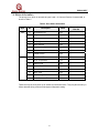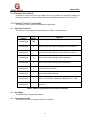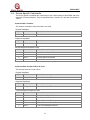
1
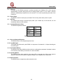
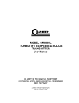
Model IR5500
Infrared Open Path Gas Detector
HART Field Device
Specification
The information and technical data disclosed in
this document may be used and disseminated
only for the purposes and to the extent
specifically authorized in writing by General
Monitors.
Instruction Manual
10-10
General Monitors reserves the right to change
published specifications and designs without
prior notice.
MANIR5500H
Part No.
Revision
MANIR5500H
A/10-10
IR5500 HART
This page intentionally left blank
2
IR5500 HART
Table of Contents
1.0
INTRODUCTION................................................................................................................................ 6
1.1
1.2
1.3
SCOPE ............................................................................................................................................. 6
PURPOSE ......................................................................................................................................... 6
REFERENCES.................................................................................................................................... 6
2.0
DEVICE IDENTIFICATION ................................................................................................................ 6
3.0
PRODUCT OVERVIEW ..................................................................................................................... 6
4.0
PRODUCT INTERFACES ................................................................................................................. 7
4.1
PROCESS INTERFACE ........................................................................................................................ 7
4.1.1
Sensor Input Channels............................................................................................................ 7
4.2
HOST INTERFACE .............................................................................................................................. 7
4.2.1
Analog Output: Lower Explosive Limit Meter (LEL.m) ............................................................ 7
4.3
LOCAL INTERFACES, JUMPERS, AND SWITCHES .................................................................................. 7
4.3.1
Local Controls And Displays ................................................................................................... 7
4.3.2
Internal Jumpers And Switches............................................................................................... 7
5.0
DEVICE VARIABLES ........................................................................................................................ 7
6.0
DYNAMIC VARIABLES..................................................................................................................... 7
6.1
6.2
6.3
6.4
PRIMARY VARIABLE = LOWER EXPLOSIVE LIMIT METER (LEL.M) ......................................................... 7
SECONDARY VARIABLE = GAS READING IN PART PER MILLION METER (PPM.M).................................... 7
TERTIARY AND QUATERNARY VARIABLES = ANALOG OUTPUT (MA)...................................................... 7
QUATERNARY VARIABLES: NOT APPLICABLE ...................................................................................... 7
7.0
STATUS INFORMATION................................................................................................................... 8
8.0
UNIVERSAL COMMANDS................................................................................................................ 9
9.0
COMMON PRACTICE COMMANDS ................................................................................................ 9
9.1
9.2
9.3
10.0
SUPPORTED COMMANDS ................................................................................................................... 9
BURST MODE.................................................................................................................................... 9
CATCH DEVICE VARIABLE .................................................................................................................. 9
DEVICE SPECIFIC COMMANDS ................................................................................................ 10
Command #131: Do Abort ................................................................................................................... 10
Command #136: Set Alarm LEL.m Hi Level ........................................................................................ 10
Command #137: Set Alarm LEL.m Lo (Warn) Level ........................................................................... 11
Command #138: Set Alarm ppm.meter Level ..................................................................................... 11
Command #139: Reset Alarms............................................................................................................ 12
Command #141: Set Relay (Alarm) Configuration .............................................................................. 12
Command #142: Reset Event Happened flag ..................................................................................... 13
Command #143: Read Event Logging Counters................................................................................. 13
Command #144: Clear Event Logging Counters................................................................................. 14
Command #145: Read Warning Event Log ......................................................................................... 14
Command #146: Read Alarm Event Log ............................................................................................. 15
Command #147: Read Fault Event Log .............................................................................................. 15
Command #148: Read Maintenance Event Log.................................................................................. 16
Command #149: Set Clock .................................................................................................................. 17
Command #150: Read Clock............................................................................................................... 17
3
IR5500 HART
Command #151: Set Run Time Meter ................................................................................................. 18
Command #152: Read Run Time Meter.............................................................................................. 18
Command #154: Set Event Index........................................................................................................ 19
Command #155: Read Event Index..................................................................................................... 19
Command #156: Read Calibration Event Log ..................................................................................... 20
Command #163: Read Fast Changing Information ............................................................................. 20
Command #164: Read Slow Changing Information ............................................................................ 21
Command #165: Read Setup Information ........................................................................................... 21
Command #166: Read System Firmware Rev .................................................................................... 22
Command #167: Set Beam Block Delay ............................................................................................. 23
Command #168: Set Analog Output Beam Block Delay ..................................................................... 23
Command #170: Set Current Range ................................................................................................... 24
Command #191: End Alignment.......................................................................................................... 24
Command #195: Do Gas Check.......................................................................................................... 25
Command #197: Do Align.................................................................................................................... 25
11.0
11.1
11.2
11.3
11.4
11.5
11.6
11.7
11.8
11.9
11.10
11.11
11.12
11.13
TABLES ....................................................................................................................................... 27
IR5500 – DEVICE SPECIFIC COMMANDS SUMMARY ...................................................................... 27
IR5500 – OPERATING MODE - PV VALUES .................................................................................. 27
FAULT EVENT LOG – CAUSE DESCRIPTION ................................................................................... 28
SAMPLING RATES ........................................................................................................................ 28
POWER-UP .................................................................................................................................. 29
DEVICE RESET ............................................................................................................................ 29
SELF-TEST.................................................................................................................................. 29
COMMAND RESPONSE DELAY ...................................................................................................... 29
BUSY AND DELAYED-RESPONSE .................................................................................................. 29
LONG MESSAGES ........................................................................................................................ 29
NON-VOLATILE MEMORY ............................................................................................................. 29
OPERATING MODES ..................................................................................................................... 29
WRITE PROTECTION .................................................................................................................... 29
ANNEX A. CAPABILITY CHECKLIST....................................................................................................... 30
ANNEX B. DEFAULT CONFIGURATION.................................................................................................. 30
ANNEX B. DD MENU DIAGRAM............................................................................................................... 31
4
IR5500 HART
Table of Tables
Table 1: Field Device Identification Data ...................................................................................................... 6
Table 2: Error Status Information.................................................................................................................. 8
Table 3: IR5500 – Supported Common Practice Commands....................................................................... 9
Table 4: IR5500 – Device Specific Commands .......................................................................................... 27
Table 5: IR5500 - Operating Mode Values ................................................................................................. 28
Table 6: IR5500 - Operating Sub-Modes .................................................................................................... 28
Table 7: Fault Event Log – Cause Description ........................................................................................... 28
Table 8: Command Response Times ......................................................................................................... 29
Table 9: Capability Checklist....................................................................................................................... 30
Table 10: Default Configuration .................................................................................................................. 30
5
IR5500 HART
1.0 Introduction
1.1
Scope
The IR5500 Monitor System detector complies with HART Protocol Revision 6.0. This document
specifies all of the device specific features and documents HART Protocol implementation details.
The functionality of this Field Device is described sufficiently to allow its proper application in a
process and its complete support in HART capable Host Applications.
1.2
Purpose
This specification is designed to complement the IR5500 Instruction Manual by providing a
complete description of this field device from a HART Communications perspective. This
specification is designed to be a technical reference for HART capable host application
developers, system integrators, and knowledgeable end users.
1.3
References
DOCUMENT NAME
DOCUMENT RELATIONSHIP
HART Communications
Protocol Specifications
This is used to insure compliance with the HART
Communication Protocol.
IR5500 Instruction
Manual
This is the General Monitors, Inc. IR5500 Product
Instruction Manual.
2.0 Device Identification
The following Table 1 is the Field Device Identification Data for the instrument.
Table 1: Field Device Identification Data
Manufacturer’s
Name
General
Monitors, Inc.
Model Number
IR5500
HART ID Code
223 (DF Hex)
Device Type
Code:
135 (87 Hex)
HART Protocol
Revision
6.0
Device
Revision:
1
Number of
Device Variables
Physical Layers
Supported
Physical Device
Category
0
1
FSK
3.0 Product Overview
The Model IR5500 Infrared Open Path System is a microprocessor-based hydrocarbon gas detector
(Figure 13). The system consists of an IR Source unit and a Receiver unit that may be placed from
5-150 meters apart. The General Monitors Model IR5500 is calibrated at the factory and needs no
further calibration. The sensitivity of the Model IR5500 can be checked by placing a Test Gas Filter
in front of the Receiver unit. It is also relatively maintenance free, requiring only a periodic cleaning
of the windows to assure dependable performance. The Model IR5500 Infrared Open Path System
6
IR5500 HART
continuously monitors hydrocarbon gases in both the 0 to 5000 ppm•meter and 0 to 5 LEL•meter
range for methane. It provides two 4 to 20 mA analog signals proportional to each of the above
ranges, in addition to a digital display and an A3 (LEL•meters-Alarm), A2 (LEL•meters-Warn), A1
(ppm•meters-Warn) and FAULT relay contacts.
4.0 Product Interfaces
4.1
Process Interface
This section describes all interfaces between the devices and the measured process.
4.1.1 Sensor Input Channels
4.2
Host Interface
The HART interface uses the 4 – 20 mA current loop. Refer to the Installation Manual for
connection details.
4.2.1 Analog Output: Lower Explosive Limit Meter (LEL.m)
The primary variable is proportional to the lower explosive limit meter. A 4.0 mA output current
corresponds to zero LEL.m. 20.0 mA output current corresponds to 100 of full scale.
4.3
Local Interfaces, Jumpers, and Switches
Refer to the Installation Manual for connection details.
4.3.1 Local Controls and Displays
Local controls and displays are described in the IR5500 User Manual
4.3.2 Internal Jumpers and Switches
There are no internal jumpers or switches in the IR5500 unit.
5.0 Device Variables
There are no device variables exposed to the user.
6.0 Dynamic Variables
6.1
6.2
There are there Dynamic Variables exposed to the user.
Primary Variable = Lower Explosive Limit Meter (LEL.m)
The primary variable is proportional to the lower explosive limit. A 4.0 mA output current
corresponds to zero LEL. 20.0 mA output current corresponds to 100% of full scale.
Secondary Variable = Gas Reading in Part per Million Meter (ppm.m)
Detected gas in ppm.m.
6.3
Tertiary and Quaternary Variables = Analog Output (mA)
The secondary variable is proportional to the part per million meter. A 4.0 mA output current
corresponds to zero ppm.m. 20.0 mA output current corresponds to 100 of full scale.
6.4
Quaternary Variables: Not Applicable
There are none defined for the IR5500 product.
7
IR5500 HART
7.0 Status Information
The priority error, which is returned via bytes 0 and 1 of Common Practice Command #48, is
shown in Table 2.
Table 2: Error Status Information
Bit
LSB
0
IR Close to Low
Error
4,7
1
Dirty Lens
Error
4,7
2
IR is Low
Error
4,7
3
IR is High
Error
4,7
4
Wire Shorted
Error
4,7
5
Low Line Voltage
Error
4,7
6
Failed to Calibrate
Error
4,7
7
Failed to Zero
Error
4,7
0
Gas Check Timeout
Error
4,7
1
Over Temperature
Error
4,7
2
XMTR Fault
Error
4,7
3
Heater Fault
Error
4,7
4
Setup Menu Fault
Error
4,7
5
Misc. Fault
Error
4,7
6
Excess Negative Drift
Error
4,7
7
NVM Checksum Error
Error
4,7
MSB
Description
Device Status
Bits Set
Byte
Class
These bits may be set at power up to indicate an instrument failure. They may also be set by a
failure detected during continuous background diagnostic testing.
8
IR5500 HART
8.0 Universal Commands
Command 3 returns the current loop variable, the primary variable, the secondary variable and
the tertiary variable for a total of 19 bytes returned. Command 9 returns the PV, the SV and TV.
9.0 Common Practice Commands
The following common practice commands are implemented.
9.1
Supported Commands
The following common-practice commands shown in Table 3 are implemented:
Command
Number
Byte
Number
Command 38
N/A
Command 48
0
Returns Priority Error Status, High Byte (See Fault table 3).
Command 48
1
Returns Priority Error Status, Low Byte (See Fault table 3).
Command 48
2
Returns Error Status High Byte (See Fault table 3).
Command 48
3
Returns Error Status Low Byte (See Fault table 3).
Command 48
4
Returns Power Cycled Flag
Command 48
5
Returns Event Happened Flag
Command 48
6
Value = 0: All OK; Bit 0: Maintenance Required; Bit 1: Fault
Command 48
7
Returns 0
Meaning
Reset Configuration Changed Flag.
Table 3: IR5500 – Supported Common Practice Commands
9.2
Burst Mode
The IR5500 does not support Burst Mode.
9.3
Catch Device Variable
This Field Device does not support Catch Device Variable.
9
IR5500 HART
10.0 Device Specific Commands
The Device Specific commands are used strictly for the unique features of the IR5500 and at the
discretion of General Monitors. They are described here in section 10.0 and are summarized in
Table 4
Command #131: Do Abort
This sends a command to set active head to run mode.
Request Data Bytes
Byte
0
Format
Description
N/A
N/A
Response Data Bytes
Byte
0
Format
Description
N/A
N/A
Command-Specific Response Codes
Code
Class
Description
0
Success
1-5
6
No Command-Specific Errors
Undefined
Error
7 - 127
Device Specific Command
Undefined
Command #136: Set Alarm LEL.m Hi Level
This sets the Alarm Hi level for LEL.m
Request Data Bytes
Byte
0
Format
Description
Unsigned-8
Alarm Hi level, % of FS
Response Data Bytes
Byte
0
Format
Description
Unsigned-8
Alarm Hi level, % of FS
Command-Specific Response Codes
Code
Class
Description
0
Success
No Command-Specific Errors
1–2
N/A
Undefined
3
Error
Passed Parameter Too Large
4
Error
Passed Parameter Too Small
5
Error
Too Few Data Bytes Received
10
IR5500 HART
Code
6 – 127
Class
Description
N/A
Undefined
Command #137: Set Alarm LEL.m Lo (Warn) Level
This sets the Alarm Lo (Warn) level for LEL.m
Request Data Bytes
Byte
0
Format
Description
Unsigned-8
Alarm Lo (warn) level, % of FS
Response Data Bytes
Byte
0
Format
Description
Unsigned-8
Alarm Lo (warn) level, % of FS
Command-Specific Response Codes
Code
Class
Description
0
Success
No Command-Specific Errors
1–2
N/A
Undefined
3
Error
Passed Parameter Too Large
4
Error
Passed Parameter Too Small
5
Error
Too Few Data Bytes Received
6 – 127
N/A
Undefined
Command #138: Set Alarm ppm.meter Level
This command set Alarm ppm.m level
Request Data Bytes
Byte
0
Format
Description
Unsigned-8
Alarm ppm.m level
Response Data Bytes
Byte
0
Format
Description
Unsigned-8
Alarm ppm.m level
Command-Specific Response Codes
Code
Class
Description
0
Success
No Command-Specific Errors
1–2
N/A
Undefined
3
Error
Passed Parameter Too Large
4
Error
Passed Parameter Too Small
11
IR5500 HART
Code
Class
Description
5
Error
Too Few Data Bytes Received
6 – 127
N/A
Undefined
Command #139: Reset Alarms
This resets latching alarms.
Request Data Bytes
Byte
Format
Description
None
N/A
N/A
Response Data Bytes
Byte
Format
Description
None
N/A
N/A
Command-Specific Response Codes
Code
Class
Description
0
Success
1 - 127
No Command-Specific Errors
Undefined
Command #141: Set Relay (Alarm) Configuration
This sets relay or alarm configuration.
Request Data Bytes
Byte
Format
Description
0
Unsigned-8
Alarm LEL Hi Relay La/nL: 0 – nL, 1 - LA
1
Unsigned-8
Alarm LEL Hi Relay En/dE: 0 – dE, 1 - En
2
Unsigned-8
Alarm LEL Lo Relay La/nL: 0 – nL, 1 - LA
3
Unsigned-8
Alarm LEL Lo Relay En/dE: 0 – dE, 1 - En
4
Unsigned-8
Alarm ppm Relay La/nL: 0 – nL, 1 - LA
5
Unsigned-8
Alarm ppm Relay En/dE: 0 – dE, 1 - En
Response Data Bytes
Byte
Format
Description
0
Unsigned-8
Alarm LEL Hi Relay La/nL: 0 – nL, 1 - LA
1
Unsigned-8
Alarm LEL Hi Relay En/dE: 0 – dE, 1 - En
2
Unsigned-8
Alarm LEL Lo Relay La/nL: 0 – nL, 1 - LA
3
Unsigned-8
Alarm LEL Lo Relay En/dE: 0 – dE, 1 - En
12
IR5500 HART
4
Unsigned-8
Alarm ppm Relay La/nL: 0 – nL, 1 - LA
5
Unsigned-8
Alarm ppm Relay En/dE: 0 – dE, 1 - En
Command-Specific Response Codes
Code
0
Class
Description
Success
No Command-Specific Errors
1-4
5
Undefined
Error
6 - 127
Too Few Data Bytes Received
Undefined
Command #142: Reset Event Happened flag
Request Data Bytes
Byte
Format
Description
None
N/A
N/A
Response Data Bytes
Byte
Format
Description
None
N/A
N/A
Command-Specific Response Codes
Code
Class
Description
0
Success
1 - 15
16
No Command-Specific Errors
Undefined
Error
17 - 127
Access Restricted
Undefined
Command #143: Read Event Logging Counters
Reads the 5 event logging counters.
Request Data Bytes
Byte
Format
Description
None
N/A
N/A
Response Data Bytes
Byte
Format
Description
0-1
Unsigned-16
Warning Event Counter
2-3
Unsigned-16
Alarm Event Counter
13
IR5500 HART
4-5
Unsigned-16
Fault Event Counter
6-7
Unsigned-16
Maintenance Event Counter
8-9
Unsigned-16
Calibrate Event Counter
Command-Specific Response Codes
Code
Class
Description
0
Success
1-127
No Command-Specific Errors
Undefined
Command #144: Clear Event Logging Counters
This resets the 5 event logging counters in the active head to zero.
Request Data Bytes
Byte
Format
Description
None
N/A
N/A
Response Data Bytes
Byte
Format
Description
None
N/A
N/A
Command-Specific Response Codes
Code
Class
Description
0
Success
1-127
No Command-Specific Errors
Undefined
Command #145: Read Warning Event Log
This reads Warning Event Log as specified by the event log number. Event 0 is the most recent
event. Event 1 is the one just before that and so forth.
Request Data Bytes
Byte
Format
Description
None
N/A
N/A
Response Data Bytes
Byte
Format
Description
0-3
Unsigned-32
Event Running Time (in Seconds)
4– 6
Date
Event Date: Day, Month, Year – 1900
7
Unsigned-8
Event Hour
8
Unsigned-8
Event Minute
14
IR5500 HART
9
Unsigned-8
Event Second
10,11
Unsigned- 16
N/A (Head Number)
12,13
Unisigned-16
Warning Code: 0 -LEL Warn, 1 - ppm Warn
Command-Specific Response Codes
Code
Class
Description
0
Success
1-127
No Command-Specific Errors
Undefined
Command #146: Read Alarm Event Log
This reads Alarm Event Log as specified by the event log number. Event 0 is the most recent
event. Event 1 is the one just before that and so forth.
Request Data Bytes
Byte
Format
Description
None
N/A
N/A
Response Data Bytes
Byte
Format
Description
0-3
Unsigned-32
Event Running Time (in Seconds)
4– 6
Date
Event Date: Day, Month, Year – 1900
7
Unsigned-8
Event Hour
8
Unsigned-8
Event Minute
9
Unsigned-8
Event Second
10,11
Unsigned- 16
0
12,13
Unisigned-8
Reserved = 0
Command-Specific Response Codes
Code
Class
Description
0
Success
1-127
No Command-Specific Errors
Undefined
Command #147: Read Fault Event Log
This reads Fault Event Log as specified by the event log number. Event 0 is the most recent
event. Event 1 is the one just before that and so forth.
Request Data Bytes
Byte
Format
Description
None
N/A
N/A
15
IR5500 HART
Response Data Bytes
Byte
Format
Description
0-3
Unsigned-32
Event Running Time (in Seconds)
4– 6
Date
Event Date: Day, Month, Year – 1900
7
Unsigned-8
Event Hour
8
Unsigned-8
Event Minute
9
Unsigned-8
Event Second
10-11
Unsigned-16
0
12-13
Unsigned-16
Event Cause – See device specific table
Command-Specific Response Codes
Code
Class
Description
0
Success
1-127
No Command-Specific Errors
Undefined
Command #148: Read Maintenance Event Log
This reads Maintenance Event Log as specified by the event log number. Event 0 is the most
recent event. Event 1 is the one just before that and so forth.
Request Data Bytes
Byte
Format
Description
None
N/A
N/A
Response Data Bytes
Byte
Format
Description
0
Unsigned-8
Event Log Number
0-3
Unsigned-32
Event Running Time (in Seconds)
4– 6
Date
Event Date: Day, Month, Year – 1900
7
Unsigned-8
Event Hour
8
Unsigned-8
Event Minute
9
Unsigned-8
Event Second
10-11
Unsigned-16
0
12-13
Unsigned-16
Maintenance Code: 0 – Gas Check, 3 - Alignment
Command-Specific Response Codes
Code
Class
Description
0
1-127
Success
No Command-Specific Errors
Undefined
16
IR5500 HART
Command #149: Set Clock
This sets the internal real-time clock.
Request Data Bytes
Byte
Format
Description
0–2
Date
Date: Day, Month, Year-1900
3
Unsigned-8
Hours
4
Unsigned-8
Minutes
5
Unsigned-8
Seconds
Response Data Bytes
Byte
Format
Description
0–2
Date
Date: Day, Month, Year-1900
3
Unsigned-8
Hours
4
Unsigned-8
Minutes
5
Unsigned-8
Seconds
Command-Specific Response Codes
Code
0
Class
Description
Success
No Command-Specific Errors
1-4
5
Undefined
Error
6 - 127
Too Few Data Bytes Received
Undefined
Command #150: Read Clock
This reads the internal real-time clock setting.
Request Data Bytes
Byte
0
Format
Description
N/A
N/A
Response Data Bytes
Byte
Format
Description
0–2
Date
Date: Day, Month, Year-1900
3
Unsigned-8
Hours
4
Unsigned-8
Minutes
5
Unsigned-8
Seconds
17
IR5500 HART
Command-Specific Response Codes
Code
Class
Description
0
Success
1-127
No Command-Specific Errors
Undefined
Command #151: Set Run Time Meter
This sets the internal run time meter.
Request Data Bytes
Byte
Format
Description
0-3
Unsigned-32
Run Time Meter Value
Response Data Bytes
Byte
Format
Description
0-3
Unsigned-32
Run Time Meter Value
Command-Specific Response Codes
Code
0
Class
Description
Success
No Command-Specific Errors
1-4
5
Undefined
Error
6 - 127
Too Few Data Bytes Received
Undefined
Command #152: Read Run Time Meter
This reads the internal run time meter.
Request Data Bytes
Byte
0
Format
Description
N/A
N/A
Response Data Bytes
Byte
Format
Description
0-3
Unsigned-32
Run Time Meter Value
Command-Specific Response Codes
Code
Class
Description
0
1-127
Success
No Command-Specific Errors
Undefined
18
IR5500 HART
Command #154: Set Event Index
This sets the index of logged event to read.
0 – latest event
Request Data Bytes
Byte
0
Format
Description
Unsigned-8
Sets index of logged event to read using commands 143 – 146.
Range 0 – 9.
Response Data Bytes
Byte
0
Format
Description
Unsigned-8
Event Index
Command-Specific Response Codes
Code
Class
Description
0
Success
1-2
3
Undefined
Error
4
5
No Command-Specific Errors
Passed Parameter Too Large
Undefined
Error
6 - 127
Too Few Data Bytes Received
Undefined
Command #155: Read Event Index
This reads event logged index.
Request Data Bytes
Byte
Format
Description
None
N/A
N/A
Response Data Bytes
Byte
0
Format
Description
Unsigned - 8
Event index
Command-Specific Response Codes
Code
Class
Description
0
1-127
Success
No Command-Specific Errors
Undefined
19
IR5500 HART
Command #156: Read Calibration Event Log
This reads Maintenance Event Log as specified by the event log number. Event 0 is the most
recent event. Event 1 is the one just before that and so forth.
Request Data Bytes
Byte
Format
Description
None
N/A
N/A
Response Data Bytes
Byte
Format
Description
0
Unsigned-8
Event Log Number
0-3
Unsigned-32
Event Running Time (in Seconds)
4– 6
Date
Event Date: Day, Month, Year – 1900
7
Unsigned-8
Event Hour
8
Unsigned-8
Event Minute
9
Unsigned-8
Event Second
10-11
Unsigned-16
N/A
12-13
Unsigned-16
Calibrate Code: 1 – Zero, 2 – Cal LEL, 3 – Cal ppm
Command-Specific Response Codes
Code
Class
Description
0
Success
1-127
No Command-Specific Errors
Undefined
Command #163: Read Fast Changing Information
This reads the fast changing information from the active head.
Request Data Bytes
Byte
Format
Description
None
N/A
N/A
Response Data Bytes
Byte
Format
Description
0-1
Unsigned-16
Mode
2-3
Unsigned-16
Sub Mode
4–7
Float
Primary Analog Output (reflect to % LEL.m level)
8–9
Unsigned-16
Priority fault
Bit map
Error status
Unsigned-8
Alarm status : 0 – off, 1 – on
10 – 11
12
20
IR5500 HART
13
Unsigned-8
Warn status : 0 – off, 1 – on
14
Unsigned-8
Alarm ppm status : 0 – off, 1 – on
15
Unsigned-8
Power cycled flag
16
Unsigned-8
Event happened flag
17-20
Integer-8
% of FS
21-24
Integer-32
ppm level
25
Unsigned-8
Reserved = 0
26-29
Float
Secondary Analog Output (reflect to ppm.m )
30-31
Unsigned -16
AJ Number
Command-Specific Response Codes
Code
Class
Description
0
Success
1-127
No Command-Specific Errors
Undefined
Command #164: Read Slow Changing Information
Request slow changing information from the active head.
Byte
Format
Description
None
N/A
N/A
Response Data Bytes
Byte
Format
Description
0-1
signed-16
Temperature
2-5
float
Voltage
6-7
signed-16
% blockage or gain
Command-Specific Response Codes
Code
Class
Description
0
Success
1-127
No Command-Specific Errors
Undefined
Command #165: Read Setup Information
Request setup information from the active head.
Request Data Bytes
Byte
Format
Description
None
N/A
N/A
21
IR5500 HART
Response Data Bytes
Byte
0
Format
Description
Unsigned-8
Gas ID
100: Methane NFPA 101: Propane NFPA
114: Methane IEC
115: Propane IEC
1
Enumerated
Measured Units – 240 Factory defined for LEL.m
2-5
Unsigned-32
Full Scale
6
Unsigned-8
Alarm LEL.m level, % of FS
7
Unsigned-8
Alarm LEL.m Relay La/nL: 0 – nL, 1 - LA
8
Unsigned-8
Alarm LEL.m Relay En/dE: 0 – dE, 1 - En
9
Unsigned-8
Alarm Warn LEL.m level, % of FS
10
Unsigned-8
Alarm Warn LEL.m Relay La/nL: 0 – nL, 1 - LA
11
Unsigned-8
Alarm Warn LEL.m Relay En/dE: 0 – dE, 1 - En
12
Unsigned-8
Warn ppm.m level, % of FS
13
Unsigned-8
Warn ppm.m Relay La/nL: 0 – nL, 1 - LA
14
Unsigned-8
Warn ppm.m Relay En/dE: 0 – dE, 1 - En
15
Unsigned-8
Beam Block Delay Time
16
Unsigned-8
AO Beam Block Delay Time
17
Unsigned-8
Reserved = 0
18-19
Unsigned-16
Reserved = 0
20
Unsigned-8
0
21
Unsigned-8
0
22
Unsigned-8
Calibration Level = 50
23
Unsigned-8
0
24
Unsigned-8
Current Range – 0: 3.5mA – 20mA ; 1: 1.25mA – 20mA
Command-Specific Response Codes
Code
Class
Description
0
Success
1-127
No Command-Specific Errors
Undefined
Command #166: Read System Firmware Rev
This command read the system firmware revision
Request Data Bytes
Byte
Format
Description
None
N/A
N/A
22
IR5500 HART
Response Data Bytes
Byte
0
Format
Description
Unsigned-8
System Firmware Revision. ASCII code
Command-Specific Response Codes
Code
Class
Description
0
Success
1-127
No Command-Specific Errors
Undefined
Command #167: Set Beam Block Delay
This sets the beam block delay time from 0 – 60 minutes.
Request Data Bytes
Byte
0
Format
Description
Unsigned-8
Beam block delay time
Response Data Bytes
Byte
0
Format
Description
Unsigned-8
Beam block delay time
Command-Specific Response Codes
Code
Class
Description
0
Success
1-2
3
Undefined
Error
4
5
No Command-Specific Errors
Passed Parameter Too Large
Undefined
Error
6 - 127
Too Few Data Bytes Received
Undefined
Command #168: Set Analog Output Beam Block Delay
This sets the current beam block delay time from 0 – 60 seconds.
Request Data Bytes
Byte
0
Format
Description
Unsigned-8
AO beam block delay time
Response Data Bytes
Byte
0
Format
Description
Unsigned-8
AO beam block delay time
23
IR5500 HART
Command-Specific Response Codes
Code
Class
Description
0
Success
No Command-Specific Errors
1-2
3
Undefined
Error
Passed Parameter Too Large
4
5
Undefined
Error
Too Few Data Bytes Received
6 - 127
Undefined
Command #170: Set Current Range
This sets the current range to be either one of 2 possible selections.
Request Data Bytes
Byte
0
Format
Description
Unsigned-8
0 – Range 3.5mA - 20mA, 1 -- Range 1.25 - 20mA
Response Data Bytes
Byte
0
Format
Description
Unsigned-8
0 – Range 3.5mA - 20mA, 1 -- Range 1.25 - 20mA
Command-Specific Response Codes
Code
Class
Description
0
Success
No Command-Specific Errors
1-2
3
Undefined
Error
Passed Parameter Too Large
4
5
Undefined
Error
Too Few Data Bytes Received
6 - 127
Undefined
Command #191: End Alignment
This sends a request to the end alignment.
Request Data Bytes
Byte
0
Format
Description
N/A
N/A
Response Data Bytes
Byte
0
Format
Description
N/A
N/A
24
IR5500 HART
Command-Specific Response Codes
Code
Class
Description
0
Success
1-5
6
Undefined
Error
5 - 15
16
No Command-Specific Errors
Device Specific Command Error
Undefined
Error
17 - 127
Access Restricted
Undefined
Command #195: Do Gas Check
This sends a request to the active unit to put the unit to Gas Check mode.
Request Data Bytes
Byte
0
Format
Description
N/A
N/A
Response Data Bytes
Byte
0
Format
Description
N/A
N/A
Command-Specific Response Codes
Code
Class
Description
0
Success
1-2
No Command-Specific Errors
Undefined
3
Error
Parameter too Large
4
Error
Parameter too Small
5 - 15
16
Undefined
Error
17 - 127
Access Restricted
Undefined
Command #197: Do Align
This sends a request to the active unit to put the unit to Align mode.
Request Data Bytes
Byte
0
Format
Description
N/A
N/A
Response Data Bytes
Byte
0
Format
Description
N/A
N/A
25
IR5500 HART
Command-Specific Response Codes
Code
Class
Description
0
Success
1–2
No Command-Specific Errors
Undefined
3
Error
Parameter too Large
4
Error
Parameter too Small
5 – 15
16
17 – 127
Undefined
Error
Access Restricted
Undefined
26
IR5500 HART
11.0 Tables
11.1 IR5500 – Device Specific Commands Summary
The following Table 4 is a summary of the IR5500 Device Specific Commands. The Reg values in
the Meaning Column denote the corresponding Modbus Register.
Table 4: IR5500 – Device Specific Commands
Command
Number
Byte Number
131
136
137
138
139
141
142
143
144
145
146
147
148
149
150
151
152
154
155
156
163
164
165
166
167
168
170
191
195
196
Meaning
Do Abort
Set Alarm LEL.m Hi Level
Set Alarm LEL.m Lo (Warn) Level
Set Alarm ppm.m Level
Reset Alarms
Set Relay (Alarm) Configuration
Reset Event Happening Flag
Read Event Logging Counters
Clear Event Logging Counters
Read Warning Event Log
Read Alarm Event Log
Read Fault Event Log
Read Maintenance Log
Set Clock
Read Clock
Set Run Time Meter
Read Run Time Meter
Set Event Index
Read Event Index
Read Calibration Event
Read Fast Changing Information
Read Slow Changing Information
Read Setup Information
Read System FW Rev.
Set Beam Block Delay Time
Set AO Beam Block Delay Time
Set Current (AO) Range
End Align
Do Gas Check
Do Align
11.2 IR5500 – Operating Mode - PV Values
The following Table 5 is a summary of the IR5500 Operating Mode Values:
Operating Mode
Value in Decimal
1
2
4
8
RUNNING
CALIBRATION
ZEROING
CAL IN PROCESS
27
IR5500 HART
Operating Mode
APPLY GAS
REMOVE GAS
STARTUP
TEMPERATURE CORRECTION
ALIGN MODE
GAS CHECK
ZERO / CAL
Value in Decimal
16
32
64
128
256
512
1024
Table 5: IR5500 - Operating Mode Values
Operating Sub-Mode
<blank>
ppm.m Warn
Warn
Warn & ppm.m Warn
Alarm
Alarm & ppm.m Warn
Alarm & Warn
Alarm, Warn & ppm.m Warn
Value in Decimal
0
1
2
3
4
5
6
7
Table 6: IR5500 - Operating Sub-Modes
11.3 Fault Event Log – Cause Description
The following Table 7 describes the cause as reported by the read event log commands:
Bits
0x0000
0x0001
0x0002
0x0004
0x0008
0x0010
0x0020
0x0040
0x0080
0x0100
0x0200
0x0400
0x0800
0x1000
0x2000
0x4000
0x8000
Cause
<none>
CLOSE TO LOW IR
DIRTY LENS
LOW IR
HIGH IR
WIRE SHORTED
LOW LINE VOLTS
FAILED TO CALIBRATE
FAILED TO ZERO
GAS CHECK TIME OUT
OVER TEMPERATURE
XMTR FAULT
HEATER FAILURE
FAILED SET UP MENU
MISC. FAULT
EXCESS NEGATIVE DRIFT
NVM CHECKSUM FAULT
Table 7: Fault Event Log – Cause Description Performance
11.4 Sampling Rates
The IR5500 samples each detector at 1 msec intervals.
28
IR5500 HART
11.5 Power-up
On power up, the IR5500 executes a self-test procedure (unit displays ‘SU’), which requires
approximately 2 minutes. During this time, the analog output is set to 1.25 or 3.5mA. After the
self-test is satisfactorily completed, the unit sets the PV to a value representing the mode of the
instrument.
11.6 Device Reset
The IR5500 cannot be reset by any command. The unit only resets when power is cycled.
11.7 Self-Test
The IR5500 goes through a self-test upon power cycle. Should any of the tests fail, the unit
immediately reports a fault condition.
11.8 Command Response Delay
The IR5500 responds as follows:
Response
Type
Response
Time
Minimum
20ms
Typical
50ms
Maximum
100ms
Table 8: Command Response Times
11.9 Busy and Delayed-Response
The IR5500 does not use delayed-response times.
11.10 Long Messages
The largest data field used by the IR5500 is in response to Command 21: 34 bytes including the
two status bytes.
11.11 Non-Volatile Memory
The IR5500 uses external NVM to hold the device’s configuration parameters. New data is written
to this memory immediately on execution of a write command.
11.12 Operating Modes
The IR5500 reports lower explosive limit meter (LEL.m) and part per million meter (ppm.m)
detected. Various other modes are supported related to the calibration of the instrument.
11.13 Write Protection
The IR5500 does not support any write protection mode.
29
IR5500 HART
Annex A. Capability Checklist
Manufacturer, model, and revision
General Monitors, Inc., IR5500, Revision 1
Device type
IR Open Path Gas Detector
HART revision
6.0
Device Description available
Yes
Number and type of sensors
1
Number and type of actuators
0
Number and type of host side signals
2: 4 - 20mA analog
Number of Device Variables
0
Number of Dynamic Variables
3
Mappable Dynamic Variables?
No
Number of common-practice commands
2
Number of device-specific commands
30
Bits of additional device status
8
Alternative operating modes?
No
Burst mode?
No
Write-protection?
Mfg Only
Table 9: Capability Checklist
Annex B. Default Configuration
Parameter
Default value
Lower Range Value
N/A
Upper Range Value
N/A
PV Units
LEL.m (Percent Lower Explosive Limit meter)
Secondary Units
ppm.m (Part Per Million meter)
Tertiary Units
mA
Sensor type
IR
Number of wires
3
Damping time constant
N/A
Fault-indication jumper
N/A
Write-protect jumper
N/A
Number of response preambles
5
Table 10: Default Configuration
30
IR5500 HART
Annex B. DD menu diagram
31