1
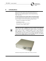
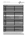
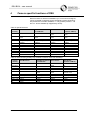
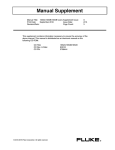
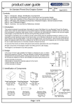
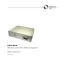
DSU-BOX DSU dome converter TTY / RS422, housing version User manual (issue 11.2013) DSU BOX – user manual 1 Safety – Before starting-up operation, maintaining, transporting, or storing this product, read the safety advices for this product, as well as the entire instruction – Pay attention to the warning notices in the succeeding chapters – Keep this document for later use or for handing it over together with the product – In addition, regard the local safety standards or laws for planning, installation, operation, and proper disposal of the product 1.1 Symbol Meaning Dangerous situation Useful information 1.2 Meaning of Precautionary Statements The seriousness of a hazard is expressed by the chosen signal word. Following signal words will be used in case of an appropriate hazard: Issue 11.2013 Signal word Meaning Danger Indicates a hazardous situation which, if not avoided, will result in death or serious injury. Warning Indicates a hazardous situation which, if not avoided, could result in death or serious injury. Caution Indicates a hazardous situation which, if not avoided, could result in minor or moderate injury. 2/11 DSU BOX – user manual 1.3 Authorized Persons Danger of life for persons without necessary qualification Only skilled personnel are allowed to work on the device! Warning Disregarding this can cause death, serious injury, or considerable property damage. This document does exclusively address the following target audience: – installer – maintainer Qualification Function Has expert knowledge in the field of electric installations and knows electrical hazards of any kind. Set-up the product Maintain the product Dismantle the product Comply with the appropriate safety regulations for low voltage systems, especially general safety and installation regulations. 1.4 Device-specific Advices – Proper and safe functioning of the device depends on appropriate transport, storage, installation, and on accurate operation and maintenance. – Use only the power supply recommended by the manufacturer. Danger of life by electric shock The interior of the power supply contains energized conductors. Do not open the power supply! Warning Disregarding this can cause death, serious injury, or considerable property damage. – Comply with the environmental conditions specified by the manufacturer Issue 11.2013 3/11 DSU BOX – user manual – Modifications of the device are only allowed as far as they are mentioned in this document or explicitly allowed by the manufacturer – Use only spare parts and accessories approved by the manufacturer – The device may only be operated when dry and undamaged – High temperature variations can cause accumulation of moisture inside the device (e.g. after transport). Power-on the device only after the temperature of the device is adapted to room ambient temperature – Only use wall plug adapters or wall power supplies complying with local permissions or regulations Electrostatic Discharge Electrostatic discharge can damage or destroy components Do not touch parts at risk (e.g. contacts of plugs) Before touching a device, discharge your body electrostatically (e.g. by touching a grounded metallic object) Issue 11.2013 4/11 DSU BOX – user manual 2 Introduction DSU module transfers video matrix’ Siemens SCU protocol of TTY interface to one dome protocol, which is provided at output port, RS485 (TX only) or RS422 (full duplex, reverse channel will not be used), respectively. According to firmware version, DSU is able to control dome cameras of several manufactures by using their specific communication protocol, one protocol per each firmware version. This manual is indented for DSU, hardware version 08 and following firmware-versions: - CCDA14x5 or SpeedDome Ultra („NRA“) - SivisMiniDome („NCS“) - Pelco D protocol, several types („NPE“) - JVC-Dome, Protocol JCBP-S („NJV“) Using DSU connected to a Simatrix SYS, 648 or 164 requires video matrix firmware version from date: 14.06.2006. Actual firmware version can be indicated by clicking „options“ button at parametrization software (firmware: 14.06.2006) or by taking a look at label of EPROM (located at video matrix mainboard). VM…_0606_X14 is means to 14.06.2006. Alternatively, checksum (which is indiacted during video matrix startup), can be used for determing firmware version. Mentioned firmware equals to checksum $1C04 (SIMATRIX SYS), $8C12 (SIMATRIX 648) or $89F2 (SIMATRIX 164), respectively. Aluminium housing version of DCU dome converter, front view Issue 11.2013 5/11 DSU BOX – user manual 2.1 Number of Domes DSU module is able to control up to 32 domes on same bus, according to RS485 specification. It is possible to control up to 16 different domes at same time. If more than 32 domes should be controlled physically, or domes should be controlled in a star-shaped manner, a RS485/RS422 multiplexer would be required, f.e. type RS485MX16, which provides 16 RS485 outputs or 16 RS422 full duplex ports, respectively. 3 Setting-up for Operation 3.1 Environmental Conditions – Comply with the environmental conditions specified by the manufacturer – operating temperature: + 5C to 45C – relative humidity: 30 to 85 %, non-condensing – Protect the device from moisture and fluids – Do not expose the device to direct thermal radiation (e.g. heating devices) – Do not operate the device in very dusty environments – Do not operate the device in the neighbourhood of a strong source of electromagnetic waves – Do not expose the device to mechanical shocks – If DSU controls domes, which are located outside the building, where video matrix is installed, a lightning protection (coarse protection) is required at control lines – Control lines, which are installed at rough electrical in parallel to ac power lines conditions have to be equipped with a surge-protection (f.e. Phoenix), before connecting to DSU – DSU complies to requirements for surge according to EN 61000-4- 5, class 2 and requirements for burst according to EN 61000-4-4, test level 2. Issue 11.2013 6/11 DSU BOX – user manual 3.2 Installation Connect DSU module “TTY input” to unused “Terminal” connector of SIMATRIX video matrix, by using a 1:1 direct connection cable (male/female, maximum length: 5m). DSU will be supplied with power from video matrix via this cable. Do not connect an additional external power supply to DSU! If distance between DSU and video matrix is greater than 5m, power has to be supplied by an external power supply 12V/200mA (not part of the delivery, available on request). Only Pin 3 and 4 of “TTY input” must be used in this case, not pin 6 and 7 (cable length: up to 1200m). Connecting an external power supply to DSU – Disconnect all plugs from DSU – Unscrew two upper screws on each side of housing to remove top cover of DSU (i.e. four screws in total) – Remove top cover of DSU – Cable of power supply should be passed through feed-through hole, dismantled and connected to two-pole power supply terminal block (use a screwdriver to release clamp lever) – Prior closing and screwing housing, perform a short test for function. Status LED must blink green Remark: LED will be unilluminated, if polarity is wrong 3.3 Configuration Some DSU configuration by internal DIP switches is dependent on firmware version. Firmware version is printed on label inside DSU (three letters). Following tables will describe DIP switch function according to firmware version: Issue 11.2013 7/11 DSU BOX – user manual NCS – SivisMiniDome Switch S1 S2 S3 S4 S5 S6 S7 S8 Switch setting „off“ – – – Dome baudrate 9600 Baud Dome parity „None“ (8N1) – Terminal filter active reserved Switch setting „on“ Video matrix baudrate 2400 Baud Video matrix baudrate 4800 Baud Video matrix baudrate 9600 Baud Dome baudrate 19200 Baud Dome parity „Even“ (8E1) Switch must be set to „on“ Terminal filter inactive reserved NRA – SpeedDome Ultra, CCDA14x5 Switch S1 S2 S3 S4 S5 S6 S7 S8 Switch setting „off“ – – – Dome baudrate 9600 Baud Menu control via pos commands: Pos 60..72 according to table of chapter 5 – Terminal filter active Varispeed characteristic matched to SpeedDome Ultra, RAS816 Switch setting „on“ Video matrix baudrate 2400 Baud Video matrix baudrate 4800 Baud Video matrix baudrate 9600 Baud Dome baudrate 19200 Baud Menu control via pos commands: Pos commands would be sended transparently (refer to dome manual) Switch must be set to „on“ Terminal filter inactive Varispeed characteristic matched to CCDA1425, CCDA1435 NPE – Protocol Pelco-D, several dome types Switch S1 S2 S3 S4 S5 S6 S7 S8 Switch setting „off“ – – – Dome baudrate 9600 Baud Varispeed characteristic: linear – Terminal filter active Reserved Switch setting „on“ Video matrix baudrate 2400 Baud Video matrix baudrate 4800 Baud Video matrix baudrate 9600 Baud Dome baudrate 19200 Baud Varispeed characteristic: optimiert for SpeedDome 2 Switch must be set to „on“ Terminal filter inactive reserved NJV – JVC-Dome, Protocol JCBP-S Switch S1 S2 S3 S4 S5 S6 S7 S8 Switch setting „off“ – – – Dome baudrate 9600 Baud Dome parity „None“ (8N1) – Terminal filter active reserved Switch setting „on“ Video matrix baudrate 2400 Baud Video matrix baudrate 4800 Baud Video matrix baudrate 9600 Baud Dome baudrate 19200 Baud Dome parity „Even“ (8E1) Switch must be set to „on“ Terminal filter inactive reserved Remarks: Video matrix baudrate setting of DSU must match to terminal baudrate of video matrix Terminal filter must be set to „on“, if DSU is operated at Simatrix 164, 168 or 648. Issue 11.2013 8/11 DSU BOX – user manual 4 Camera specific functions of DSU Dome functions for which no standard key of control unit is assigned, can be accessed via position preset commands, instead. Used position presets are not further available, i.e. only position presets 1…60 and 73…99 are available (if supported by dome). Table of special functions: Control unit key SivisMiniDome SpeedDome Ultra VI or CCDA14x5 Pelco Domes JVC-Dome (Protocol JCBP-S) Position 61: Activate camera-menu Activate camera-menu Position 62: Deactivate cameramenu Position 63: Autofocus Position 64: Startposition (home position) Position 65: Colour Position 66: black/white Position 67: Patrol start Position 68: Patrol stop Position 69: Patrol learn Position 70: Reset dome Position 71: – Position 72: – Deactivate cameramenu Autofocus Startposition (home position) Colour/black-white – Patrol start Patrol stop Patrol learn Reset dome Patrol test Patrol save Activate cameramenu Deactivate cameramenu Autofocus Startposition (home position) – – Patrol start Patrol stop Patrol learn Stop scan – – Activate cameramenu Deactivate cameramenu Autofocus Startposition (home position) IR cut filter on (day) IR cut filter off (night) – – – – – – Table of menu functios (partially only available if camera menu was activated): Control unit key SivisMiniDome SpeedDome Ultra VI Pelco Domes or CCDA14x5 JVC-Domes (Protocol JCBP-S) Joystick or Arrow keys Zoom Tele: Zoom Wide: Focus Near: K500 / OSD Move cursor in menu Move cursor in menu Enter Back Sub menu Activate camera-menu K500 / SET K500 / up K500 / down K500 / color K500 / B/W Init Menu enter Menu up Menu down Colour Black/white Reset – – Sub menu Activate cameramenu Menu enter Menu up Menu down Colour Black/white Reset Move cursor in menu – – – Activate/Deactivate camera-menu Menu enter Menu up Menu down Colour Black/white – Issue 11.2013 9/11 Move cursor in menu – – – Activate cameramenu Menu enter Menu up Menu down Colour Black/white – DSU BOX – user manual 5 Pin assignment of DSU DSU BOX provides two 9-pole D-Sub connectors, a TTY input and RS422 output. RS422 output connector and connection status LED are located at front side of DSU. Power supple cable feed-through (12V/200mA) and TTY input connector are located on back side of DSU. Pinning „TTY input“, 9-pole D-Sub, male connector: Pin 1 2 3 4 5 6 7 8 9 Port +RX –RX GND +12V Pinning „RS422 output“, 9-pole D-Sub, female connector: Pin 1 2 3 4 5 6 7 8 9 6 Maintenance 6.1 Cleaning Port RS422 TX+ RS422 TX– – For cleaning use only a clean dry cloth – Do not use liquid cleaning agents or spray Issue 11.2013 10/11 DSU BOX – user manual 7 Transport and Storage – Keep the original device packaging for later transports – Do not expose the device to mechanical shocks Issued by Pelweckyj Videotechnik GmbH Güterstraße 2 64807 Dieburg Germany [email protected] Issue 11.2013 11/11