1
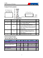
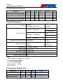
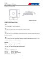
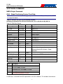
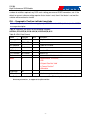
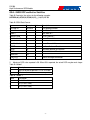
GLOBALSAT GPS Module
Hardware Data Sheet
Product No : ER-506
User Manual Version 1.1
Globalsat Technology Corporation
16F., No. 186, Jian-Yi Road, Chung-Ho City, Taipei
Hsien 235, Taiwan
Tel: 886-2-8226-3799
Fax: 886-2-8226-3899
E-mail : [email protected]
Website: www.globalsat.com.tw
Issue Date
2013/10/08
APPR
CHECK
Ray
PREPARE
Mason
-1-
ER-506
High Performance GPS Module
Product Description
Product Description
ER-506 GPS module features high sensitivity, low power and ultra small form factor. This GPS
module is powered by SiRF Star IV, it can provide you with superior sensitivity and performance
even in urban canyon and dense foliage environment. With SiRF CGEE (Client Generated
Extended Ephemeris) technology, it predicts satellite positions for up to 3 days and delivers
CGEE-start time of less than 15 seconds under most conditions, without any network assistance.
Besides, MicroPower Mode allows GPS module to stay in a hot-start condition nearly continuously
while consuming very little power. ER-506 is suitable for the following applications:
Automotive navigation
Fleet management
Marine navigation
Product Features
SiRF Star IV high performance GPS Chipset
Very high sensitivity (Tracking Sensitivity: -163 dBm)
Extremely fast TTFF (Time To First Fix) at low signal level
Support RS-232 interface.
Built-in LNA(with in CHIP)
Compact size (30.0mm x 30.0 mm x 10.7mm) suitable for space-sensitive application
Support NMEA 0183 V3.0 (GGA, GSA, GSV, RMC, VTG, GLL, ZDA)
Support OSP protocol
Support SBAS (WASS, EGNOS, MSAS, GAGAN)
-2-
ER-506
High Performance GPS Module
Product Pin Description
PIN Number(s)
Name
Type
1,5
GND
P
Ground.
2
VIN
P
This is the main power supply to the engine
board. (4.5Vdc to 6.5Vdc)
3
RXD
I
4
TXD
O
6
Directive
O
Description
Note
This is the main receive channel for
receiving software commands to the engine
board from SiRFdemo software or from user
written software. Baud rate based on flash
memory setting.
This is the main transmits channel for
outputting navigation and measurement
data to user’s navigation software or user
written software.
This pin indicates the GPS states.
Electrical Specification
Absolute Maximums Ratings
Parameter
Min.
Typ.
Max.
Conditions
Unit
4.5
5.0
6.5
45
50
55
GPS is not 3D Fixed.
mA
33
34
38
GPS is 3D Fixed.
mA
POWER Supply
Main power supply(VCC)
Main power supply Current
V
RF
Input Impendance
Operating Frequency
50
Ω
1.575
Ghz
- 10 -
ER-506
High Performance GPS Module
DC Electrical characteristics
Parameter
Symbol
Min.
Typ.
Max.
Conditions
Units
Directive Low Level Output Voltage
VOL
Directive High Level Output Voltage
VOH
3.3
V
RS-232 Low Level Output Voltage
VI L
-6
V
RS-232 High Level Output Voltage
VI H
6
V
0.4
V
Receiver Performance
Sensitivity
Tracking :
-163dBm
Autonomous acquisition :
-160 dBm
< 35s
Cold Start – Autonomous
Time-To-First-Fix1
<15s (with CGEE)
< 35s
Warm Start – Autonomous2
< 15s(with CGEE)
Hot Start – Autonomous3
< 1s
Horizontal Position Accuracy4 Autonomous
Velocity Accuracy5
< 2.5m
Speed
< 0.01 m/s
Heading
< 0.01 degrees
Reacquisition 0.1 second, average
Update Rate 1 Sec / 5 Sec
Maximum Altitude < 18,000 meter
Maximum Velocity < 515 meter/ second
Maximum Acceleration < 4G
<Note>
1. 50% -130dBm Fu 0.5ppm Tu ±2s Pu 30Km
2. Commanded Warm START
3. Commanded Hot START
4. 50% 24hr static, -130dBm
5. 50% @ 30m/s
Environmental Characteristics
Parameter
Humidity Range
Min
Typ
5
Operation Temperature
-40
Storage Temperature
-40
25
Max
Unit
95
85
% non-condensing
℃
85
℃
-3-
ER-506
High Performance GPS Module
Physical Characteristic
OPERATING Description
GND
This is Ground pin for the baseband circuit.
VIN
This is the main power supply to the engine board. (4.5Vdc to 6.5Vdc)
RXD
This is the main channel for receiving software commands from SiRFdemo software or from your
proprietary software.
TXD
This is the main transmits channel for outputting navigation and measurement data to user’s
navigation software or user written software.
Directive
This pin exports signal to indicate the GPS states.
GPS unfix: always low level.
GPS fixed: one second high level, one second low level.
LED
LED indicator for GPS fix or not fix
LED OFF:
Receiver switch off
LED ON:
No fixed, Signal searching
LED Flashing:
Position Fixed
-4-
ER-506
High Performance GPS Module
SOFTWARE COMMAND
NMEA Output Command
GGA - Global Positioning System Fixed Data
Note – Fields marked in italic red apply only to NMEA version 2.3 (and later) in this NMEA
message description
Table B-2 contains the values for the following example:
$GPGGA,161229.487,3723.2475,N,12158.3416,W,1,07,1.0,9.0,M,-34.2,M,,0000*18
Table B-2 GGA Data Format
Name
Example
Units
Description
Message ID
$GPGGA
GGA protocol header
UTC Time
161229.487
hhmmss.sss
Latitude
3723.2475
ddmm.mmmm
N/S Indicator
N
N=north or S=south
Longitude
12158.3416
dddmm.mmmm
E/W Indicator
W
E=east or W=west
Position Fix Indicator 1
See Table B-3
Satellites Used
07
Range 0 to 12
HDOP
1.0
Horizontal Dilution of Precision
MSL Altitude
9.0
meters
M
meters
Geoid Separation
-34.2
meters
Units
M
meters
Units
1
Age of Diff. Corr.
second
Diff. Ref. Station ID
0000
Checksum
*18
<CR><LF>
Geoid-to-ellipsoid separation.
Ellipsoid altitude=MSL Altitude + Geoid
Separation
Null fields when DGPS is not used
End of message termination
Table B-3 Position Fix Indicator
Value
Description
0
Fix not available or invalid
1
GPS SPS Mode, fix valid
2
Differential GPS, SPS Mode , fix valid
3
Not supported
6
Dead Reckoning Mode, fix valid
Note:
A valid status is derived from all the parameters set in the software. This includes the minimum
-7-
ER-506
High Performance GPS Module
number of satellites required, any DOP mask setting, presence of DGPS corrections, etc. If the
default or current software setting requires that a factor is met, then if that factor is not met the
solution will be marked as invalid.
GLL - Geographic Position-Latitude/Longitude
Note – Fields marked in italic red apply only to NMEA version 2.3 (and later) in this NMEA
message description
Table B-4 contains the values for the following example:
$GPGLL,3723.2475,N,12158.3416,W,161229.487,A,A*41
Table B-4 GLL Data Format
Name
Example
Message ID
$GPGLL
GLL protocol header
Latitude
3723.2475
ddmm.mmmm
N/S Indicator
n
N=north or S=south
Longitude
12158.3416
dddmm.mmmm
E/W Indicator
W
E=east or W=west
UTC Position
161229.487
hhmmss.sss
Status
A
A=data valid or V=data not valid
Mode
A
A=Autonomous, D=DGPS,
E=DR
N=Output Data Not Valid
R= Coarse Position1
S=Simulator
Checksum
*41
<CR><LF>
1.
Units
Description
End of message termination
Position was calculated based on one or more of the SVs having their states derived from
almanac parameters, as opposed to ephemerides.
-8-
ER-506
High Performance GPS Module
GSA - GNSS DOP and Active Satellites
Table B-5 contains the values for the following example:
$GPGSA,A,3,07,02,26,27,09,04,15,,,,,,1.8,1.0,1.5*33
Table B-5 GSA Data Format
Name
Example
Message ID
$GPGSA
GSA protocol header
Mode 1
A
See Table B-6
Mode 2
Units
Description
3
See Table B-7
1
07
Sv on Channel 1
1
02
Sv on Channel 2
Satellite Used
Satellite Used
…..
Satellite Used1
PDOP
1.8
Position dilution of Precision
2
1.0
Horizontal dilution of Precision
2
1.5
Vertical dilution of Precision
HDOP
VDOP
Sv on Channel 12
2
Checksum
*33
<CR><LF>
End of message termination
1. Satellite used in solution.
2. Maximum DOP value reported is 50. When 50 is reported, the actual DOP may be much larger.
Table B-6 Mode1
Value
Description
M
Manual-forced to operate in 2D or 3D mode
A
2Dautomatic-allowed to automatically switch 2D/3D
Table B-7 Mode 2
Value
Description
1
Fix Not Available
2
2D (<4 SVs used)
3
3D (>3 SVs used)
-9-
ER-506
High Performance GPS Module
GSV - GNSS Satellites in View
Table B-8 contains the values for the following example:
$GPGSV,2,1,07,07,79,048,42,02,51,062,43,26,36,256,42,27,27,138,42*71
$GPGSV,2,2,07,09,23,313,42,04,19,159,41,15,12,041,42*41
Table B-8 GSV Data Format
Name
Example
Message ID
Number of Messages
1
Message Number
1
1
Units
Description
$GPGSV
GSV protocol header
2
Range 1 to 3
1
Range 1 to 3
Satellites in View
07
Satellite ID
07
Elevation
79
degrees
Channel 1(Maximum90)
Azimuth
048
degrees
Channel 1(True, Range 0 to 359)
SNR(C/No)
42
dBHz
Range 0 to 99,null when not tracking
Channel 1(Range 1 to 32)
…….
…….
Satellite ID
27
Elevation
27
Degrees Channel 4(Maximum90)
Azimuth
138
Degrees Channel 4(True, Range 0 to 359)
SNR(C/No)
42
dBHz
Checksum
*71
<CR><LF>
1.
Channel 4 (Range 1 to 32)
Range 0 to 99,null when not tracking
End of message termination
Depending on the number of satellites tracked, multiple messages of GSV data may be
required. In some software versions, the maximum number of satellites reported as visible is
limited to 12, even though more may be visible.
- 10 -
ER-506
High Performance GPS Module
RMC - Recommended Minimum Specific GNSS Data
Note – Fields marked in italic red apply only to NMEA version 2.3 (and later) in this NMEA
message description
Table B-9 contains the values for the following example:
$GPRMC,161229.487,A,3723.2475,N,12158.3416,W,0.13,309.62,120598,,,A*10
Table B-9 RMC Data Format
Name
Example
Message ID
$GPRMC
RMC protocol header
UTC Time
161229.487
hhmmss.sss
Status
A
A=data valid or V=data not valid
Latitude
3723.2475
ddmm.mmmm
N/S Indicator
N
N=north or S=south
Longitude
12158.3416
dddmm.mmmm
E/W Indicator
W
E=east or W=west
1
Units
Description
Speed Over Ground 0.13
knots
Course Over Ground 309.62
degrees True
Date
120598
2
Magnetic Variation
ddmmyy
degrees E=east or W=west
2
East/West Indicator
E
E=east
Mode
A
A=Autonomous, D=DGPS,
E=DR
N=Output Data Not Valid
R= Coarse Position3
S=Simulator
Checksum
*10
<CR><LF>
1.
2.
3.
End of message termination
A valid status is derived from all the parameters set in the software. This includes the
minimum number of satellites required, any DOP mask setting, presence of DGPS
corrections, etc. If the default or current software setting requires that a factor is met, then if
that factor is not met the solution will be marked as invalid.
SiRF Technology Inc. does not support magnetic declination. All “course over ground” data
are geodetic WGS84 directions relative to true North.
Position was calculated based on one or more of the SVs having their states derived from
almanac parameters, as opposed to ephemerides.
- 11 -
ER-506
High Performance GPS Module
VTG - Course Over Ground and Ground Speed
Note – Fields marked in italic red apply only to NMEA version 2.3 (and later) in this NMEA
message description
Table B-10 contains the values for the following example:
$GPVTG,309.62,T,,M,0.13,N,0.2,K,A*23
Table B-10 VTG Data Format
Name
Example
Message ID
$GPVTG
Course
309.62
Reference
T
Course
Units
Description
VTG protocol header
degrees Measured heading
True
degrees Measured heading
Magnetic1
Reference
M
Speed
0.13
Units
N
Speed
0.2
Units
K
Kilometers per hour
Mode
A
A=Autonomous, D=DGPS,
E=DR
N=Output Data Not Valid
R= Coarse Position2
S=Simulator
Checksum
*23
<CR><LF>
1.
2.
knots
Measured horizontal speed
Knots
Km/hr
Measured horizontal speed
End of message termination
SiRF Technology Inc. does not support magnetic declination. All “course over ground” data
are geodetic WGS84 directions.
Position was calculated based on one or more of the SVs having their states derived from
almanac parameters, as opposed to ephemerides.
- 12 -
ER-506
High Performance GPS Module
ZDA - Time and Date
This message is included only with systems which support a time-mark output pulse identified as
"1PPS". Outputs the time associated with the current 1PPS pulse. Each message is output within
a few hundred ms after the 1PPS pulse is output and tells the time of the pulse that just occurred.
Table B-11 contains the values for the following example:
$GPZDA,181813,14,10,2003,,*4F<CR><LF>
Table B-11: ZDA Data Format
Name
Example
Message ID
$GPZDA
UTC Time
181813
Unit
Description
ZDA protocol header
The UTC time units are:
hh=UTC hours from 00 to 23 mm=UTC minutes
from 00 to 59 ss=UTC seconds from 00 to 59 Either
using valid IONO/UTC or estimated from default
hhmmss leap seconds
Day
14
Day of the month, range 1 to 31
Month
10
Month of the year, range 1 to 12
Year
2003
Year
Local zone hour1
hour
Offset from UTC (set to 00)
Local zone minutes1
minute
Offset from UTC (set to 00)
Checksum
*4F
<CR><LF>
1.
End of message termination
Not supported by CSR, reported as 00.
- 13 -
ER-506
High Performance GPS Module
NMEA Input Command
A). Set Serial Port ID: 100 Set PORTA parameters and protocol
This command message is used to set the protocol (SiRF Binary, NMEA, or USER1) and/or the
communication parameters (baud, data bits, stop bits, parity). Generally, this command would be
used to switch the module back to SiRF Binary protocol mode where a more extensive command
message set is available. For example, to change navigation parameters. When a valid message
is received, the parameters will be stored in battery backed SRAM and then the receiver will
restart using the saved parameters.
Format:
$PSRF100,<protocol>,<baud>,<DataBits>,<StopBits>,<Parity>*CKSUM<CR><LF>
<protocol>
0=SiRF Binary, 1=NMEA, 4=USER1
<baud>
1200, 2400, 4800, 9600, 19200, 38400
<DataBits> 8,7. Note that SiRF protocol is only valid f8 Data bits
<StopBits>
0,1
<Parity>
0=None, 1=Odd, 2=Even
Example 1: Switch to SiRF Binary protocol at 9600,8,N,1
$PSRF100,0,9600,8,1,0*0C<CR><LF>
Example 2: Switch to User1 protocol at 38400,8,N,1
$PSRF100,4,38400,8,1,0*38<CR><LF>
**Checksum Field: The absolute value calculated by exclusive-OR the 8 data bits of each
character in the Sentence, between, but excluding “$” and “*”. The hexadecimal value of the most
significant and least significant 4 bits of the result are convertted to two ASCII characters (0-9, A-F)
for transmission. The most significant character is transmitted first.
**<CR><LF>
: Hex 0D 0A
B). Navigation lnitialization ID:
:101 Parameters required for start
This command is used to initialize the module for a warm start, by providing current position (in X,
Y, Z coordinates),clock offset, and time. This enables the receiver to search for the correct
satellite signals at the correct signal parameters. Correct initialization parameters will enable the
receiver to acquire signals more quickly, and thus, produce a faster navigational solution.
When a valid Navigation Initialization command is received, the receiver will restart using the input
parameters as a basis for satellite selection and acquisition.
- 14 -
ER-506
High Performance GPS Module
Format:
:
$PSRF101,<X>,<Y>,<Z>,<ClkOffset>,<TimeOfWeek>,<WeekNo>,<chnlCount>,<ResetCfg>*CK
SUM<CR><LF>
<X>
X coordinate position
INT32
<Y>
Y coordinate position
INT32
<Z>
Z coordinate position
INT32
<ClkOffset>
Clock offset of the receiver in Hz, Use 0 for last saved value if available. If
this is unavailable, a default value of 75000 for GSP1, 95000 for GSP 1/LX
will be used.
INT32
<TimeOf Week>
GPS Time Of Week
UINT32
<WeekNo>
GPS Week Number
UINT16
( Week No and Time Of Week calculation from UTC time)
<chnlCount>
Number of channels to use.1-12. If your CPU throughput is not high enough,
you could decrease needed throughput by reducing the number of active
channels
UBYTE
<ResetCfg>
bit mask
0×01=Data Valid warm/hot start=1
0×02=clear ephemeris warm start=1
0×04=clear memory. Cold start=1
UBYTE
Example: Start using known position and time.
$PSRF101,-2686700,-4304200,3851624,96000,497260,921,12,3*7F
C). Set DGPS Port ID: 102 Set PORT B parameters for DGPS input
This command is used to control Serial Port B that is an input only serial port used to receive
RTCM differential corrections.
Differential receivers may output corrections using different communication parameters.
The default communication parameters for PORT B are 9600Baud, 8data bits, 0 stop bits, and no
parity. If a DGPS receiver is used which has different communication parameters, use this
command to allow the receiver to correctly decode the data. When a valid message is received,
the parameters will be stored in battery backed SRAM and then the receiver will restart using the
saved parameters.
- 15 -
ER-506
High Performance GPS Module
Format:
$PSRF102,<Baud>,<DataBits>,<StopBits>,<Parity>*CKSUM<CR><LF>
<baud>
1200,2400,4800,9600,19200,38400
<DataBits>
8
<StopBits>
0,1
<Parity>
0=None, Odd=1,Even=2
Example: Set DGPS Port to be 9600,8,N,1
$PSRF102,9600,8,1.0*12
D). Query/Rate Control ID: 103 Query standard NMEA message and/or set output rate
This command is used to control the output of standard NMEA message GGA, GLL, GSA, GSV,
RMC, VTG. Using this command message, standard NMEA message may be polled once, or
setup for periodic output. Checksums may also be enabled or disabled depending on the needs of
the receiving program. NMEA message settings are saved in battery backed memory for each
entry when the message is accepted.
Format:
$PSRF103,<msg>,<mode>,<rate>,<cksumEnable>*CKSUM<CR><LF>
<msg>
0=GGA,
1=GLL,
2=GSA,
3=GSV,
4=RMC,
5=VTG
6=MSS(if internal beacon is supported)
7=Not defined
8=ZDA(if 1PPS output supported)
9=Not defined
<mode>
0=SetRate
1=Query
2=ABP On
3=ABP Off
<rate>
Output every <rate>seconds, off=0,max=255
<cksumEnable>
0=disable Checksum,1=Enable checksum for specified message
Example 1: Query the GGA message with checksum enabled
$PSRF103,00,01,00,01*25
- 16 -
ER-506
High Performance GPS Module
Example 2: Enable VTG message for a 1Hz constant output with checksum enabled
$PSRF103,05,00,01,01*20
Example 3: Disable VTG message
$PSRF103,05,00,00,01*21
E). LLA Navigation lnitialization ID: 104 Parameters required to start using Lat/Lon/Alt
This command is used to initialize the module for a warm start, by providing current position (in
Latitude, Longitude, Altitude coordinates), clock offset, and time. This enables the receiver to
search for the correct satellite signals at the correct signal parameters. Correct initialization
parameters will enable the receiver to acquire signals more quickly, and thus, will produce a faster
navigational soution.
When a valid LLA Navigation Initialization command is received, the receiver will restart using the
input parameters as a basis for satellite selection and acquisition.
Format:
$PSRF104,<Lat>,<Lon>,<Alt>,<ClkOffset>,<TimeOfWeek>,<WeekNo>,<ChannelCount>,
<ResetCfg>*CKSUM<CR><LF>
<Lat>
Latitude position, assumed positive north of equator and negative south of
equator float, possibly signed
<Lon>
Longitude position, it is assumed positive east of Greenwich and negative
west of Greenwich Float, possibly signed
<Alt>
Altitude position float, possibly signed
<ClkOffset>
Clock Offset of the receiver in Hz, use 0 for last saved value if available. If
this is unavailable, a default value of 75000 for GSP1, 95000 for GSP1/LX
will be used.
INT32
<TimeOfWeek>
GPS Time Of Week
UINT32
<WeekNo>
GPS Week Number
UINT16
<ChannelCount>
Number of channels to use. 1-12 UBYTE
<ResetCfg>
bit mask
0×01=Data Valid warm/hot starts=1
0×02=clear ephemeris warm start=1
0×04=clear memory. Cold start=1
UBYTE
Example: Start using known position and time.
$PSRF104,37.3875111,-121.97232,0,96000,237759,922,12,3*37
- 17 -
ER-506
High Performance GPS Module
F). Development Data On/Off ID: 105 Switch Development Data Messages On/Off
Use this command to enable development debug information if you are having trouble getting
commands accepted. Invalid commands will generate debug information that should enable the
user to determine the source of the command rejection. Common reasons for input command
rejection are invalid checksum or parameter out of specified range. This setting is not preserved
across a module reset.
Format: $PSRF105,<debug>*CKSUM<CR><LF>
<debug>
Example: Debug On
Example: Debug Off
0=Off, 1=On
$PSRF105,1*3E
$PSRF105,0*3F
G). Select Datum ID: 106 Selection of datum to be used for coordinate Transformations
GPS receivers perform initial position and velocity calculations using an earth-centered earth-fixed
(ECEF) coordinate system. Results may be converted to an earth model (geoid) defined by the
selected datum. The default datum is WGS 84 (World Geodetic System 1984) which provides a
worldwide common grid system that may be translated into local coordinate systems or map
datums. (Local map datums are a best fit to the local shape of the earth and not valid worldwide.)
Examples:
Datum select TOKYO_MEAN
$PSRF106,178*32
Name
Example
Unit
Message ID
$PSRF106
PSRF106 protocol
header
Datum
178
21=WGS84
178=TOKYO_MEAN
179=TOKYO_JAPAN
180=TOKYO_KOREA
181=TOKYO_OKINAWA
Debug
Checksum
*32
<CR><LF>
Description
End of message
termination
- 18 -
ER-506
High Performance GPS Module
RoHS / Lead Free Compliance
- 19 -
ER-506
High Performance GPS Module
Reversion history
Reversion
Date
Name
Status / Comments
V1.0
20130925
Mason
Initial Version
V1.1
20131008
Mason
Modify pin 1PPS to Directive
- 20 -