1
Triskan TS8 Firmware Development Kit
User Manual
2010-10-20
Andrei Birjukov, Jaanus Sepp, Anti Sullin, Ivari Horm
© Artec Group LLC, 2010
Triskan TS8 Firmware Development Kit
User Manual
Table of Contents
1.About This Document........................................................................................................................................4
1.1.Intended Audience....................................................................................................................................4
1.2.Required Skills..........................................................................................................................................4
1.3.Conventions...............................................................................................................................................4
1.4.References................................................................................................................................................4
1.5.Vocabulary.................................................................................................................................................4
2.Introduction.......................................................................................................................................................6
2.1.FDK DVD layout.........................................................................................................................................7
2.2.Requirements...........................................................................................................................................7
3.Hardware Reference.........................................................................................................................................8
3.1.Triskan TS8 Components..........................................................................................................................8
3.2.Hardware Specifications...........................................................................................................................9
3.3.Flash Memory Layout...............................................................................................................................9
4.Installing Development Tools.........................................................................................................................11
4.1.Installing Cross-Compiler Toolchain.....................................................................................................11
4.2.Installing distCC distributed compiler servers (optional)......................................................................12
4.3.Installing Maintenance Tools..................................................................................................................14
4.4.Installing Eclipse CDT.............................................................................................................................15
5.Creating Development Tree............................................................................................................................16
5.1.Installing Firmware Build Tree...............................................................................................................16
5.2.Installing External Dependencies...........................................................................................................16
5.3.Doing Initial Build....................................................................................................................................16
5.4.Creating Eclipse Projects.......................................................................................................................18
6.Building Target Firmware...............................................................................................................................23
6.1.Firmware Build Flow..............................................................................................................................23
6.2.Building Firmware Images.....................................................................................................................25
6.3.Deploying Firmware Package.................................................................................................................25
6.4.Deploying Recovery Image......................................................................................................................27
6.5.Application Linkage................................................................................................................................28
6.6.Building User Applications.....................................................................................................................29
7.Running Applications......................................................................................................................................30
7.1.Accessing Development Console...........................................................................................................30
7.2.Transferring Files to Target...................................................................................................................31
7.3.Debugging via GDB.................................................................................................................................33
7.4.Resetting Target Device..........................................................................................................................34
8.Developing Applications..................................................................................................................................35
8.1.Storage Media.........................................................................................................................................35
8.2.Communication Interfaces.....................................................................................................................36
8.3.Scanner Interfaces..................................................................................................................................40
8.4.User Interface.........................................................................................................................................40
© Artec Group, 2010
Teaduspargi 6/2, 12618, Tallinn, Estonia
Phone: +372 671 8550
Fax:
+372 671 8555
Page 2 of 47
Triskan TS8 Firmware Development Kit
User Manual
8.5.System Interfaces...................................................................................................................................42
9.Appendix A: Auxiliary Files.............................................................................................................................45
10.Appendix B: Licensing...................................................................................................................................46
11.Appendix C: Change log................................................................................................................................47
© Artec Group, 2010
Teaduspargi 6/2, 12618, Tallinn, Estonia
Phone: +372 671 8550
Fax:
+372 671 8555
Page 3 of 47
Triskan TS8 Firmware Development Kit
User Manual
1. About This Document
This manual describes the development kit components and software development for Artec Triskan TS8
mobile data terminal, including the process of building firmware and debugging user applications.
1.1. Intended Audience
This document is intended for software engineers and system integrators who are planning to integrate the
Triskan TS8 mobile data terminal and develop firmware and applications for it.
1.2. Required Skills
To use this development kit, a developer must be familiar with the following issues and possess the
following skills.
•
Embedded Linux OS with 2.6 kernel
•
General understanding of cross-compiling and target debugging
C and C++ skills for development of applications using GNU toolchain
1.3. Conventions
This document uses the following conventions.
Courier
Used to identify source code samples, commands and their parameters,
expressions, data types, etc.
Italic
Used for emphasis and identification of file names and new terms.
$ command
Refers to a shell command executed on the host machine.
# command
Refers to a shell command executed on the target TS8 device.
1.4. References
The following documents are referenced from this document.
1.
API documentation – libspatha library.
2.
API documentation - exynthoo library.
1.5. Vocabulary
Term
Atmel SAM-BA
Definition
SAM Boot Assistant, the toolset from Atmel for programming AT91 devices.
© Artec Group, 2010
Teaduspargi 6/2, 12618, Tallinn, Estonia
Phone: +372 671 8550
Fax:
+372 671 8555
Page 4 of 47
Triskan TS8 Firmware Development Kit
User Manual
Term
Definition
Eclipse CDT
Eclipse C/C++ Development Tooling, the C and C++ IDE of the Eclipse platform.
FDK
Firmware Development Kit, a software development kit for Triskan TS8
Target
Target device, Triskan TS8 in this context.
Toolchain
A set of tools for software development.
Xynth
A lightweight GUI engine, http://www.xynth.org
eXynth
Extended Xynth library maintained by Artec. Simplifies application library routines by
minimizing threading and unifies event handling system.
eXynthoo
Extended Xytnth Object library. This library is developed by Artec to provide basic UI
components for developing graphical user interfaces to TS8 devices.
© Artec Group, 2010
Teaduspargi 6/2, 12618, Tallinn, Estonia
Phone: +372 671 8550
Fax:
+372 671 8555
Page 5 of 47
Triskan TS8 Firmware Development Kit
User Manual
2. Introduction
Triskan TS8 platform runs an embedded Linux operating system with a custom root filesystem. The
development environment of the host machine is also Linux based and employs a CodeSourcery crosscompiler toolchain for building the OS kernel, board-specific drivers, root filesystem and user space
applications and utilities. Additional libraries required to support applications are built from their original
source code packages and installed to the target filesystem.
Development kit contains the following hardware items.
•
Triskan TS8 mobile data terminal with integrated TS8-G11 GPRS communication module
-or-
•
Triskan TS8 mobile data terminal with integrated TS8-W11 WLAN communication module
•
TS8-RB1R0 reader module with 1D laser scanner
•
TS8-B201 battery
•
TS8-PR11 power supply
•
TS8-RB0R0 development adapter
•
TS8-S017 grey neck strap
•
Micro-SD card
•
2x Mini-USB cable
•
Minigrip bag with screws and boot mode selection jumper
•
Quick-start guide with attached download area credentials
•
DVD with development environment and documentation
Development kit contains the following software on the DVD media.
•
Firmware development tree archive
•
Artec libspatha hardware support library and documentation
•
Artec exynthoo C++ GUI library and documentation
•
Platform bootloader binary image
•
Bootloader splash graphics and configuration images
•
Adapted and optimized Xynth GUI engine (eXynth)
•
Linux kernel version 2.6.33.3 source code
•
Busybox version 1.16.1 source code
•
Auxiliary libraries and tools (freetype, expat, libpng, etc)
•
Eclipse Helios with CDT
•
CodeSourcery cross-compiler toolchain for ARM (arm-2010q1)
•
Documentation
© Artec Group, 2010
Teaduspargi 6/2, 12618, Tallinn, Estonia
Phone: +372 671 8550
Fax:
+372 671 8555
Page 6 of 47
Triskan TS8 Firmware Development Kit
User Manual
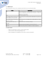
2.1. FDK DVD layout
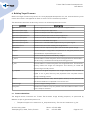
The following table contains a list of related files and directories on the provided FDK DVD.
Name
doc/
Description
Contains development kit documentation (manuals in PDF format
as well as libexynthoo and libspatha documentation as HTML files
packed into .tar.gz archive)
tools/
Contains development tools
– arm-2010q1-202-arm-none-linux-
CodeSourcery G++ Lite 2010q1-202 for ARM GNU/Linux packed into
gnueabi-i686-pc-linux-gnu.tar.bz2
archive
– arm-2010q1-202-arm-none-linux-
CodeSourcery G++ Lite 2010q1-202 for ARM GNU/Linux installer
gnueabi.src.tar.bz2
source code
- eclipse-cpp-helios-SR1-linux-
Eclipse IDE for C/C++ developers package
gtk.tar.gz
source/
Contains firmware development tree as an archive file
external/
Contains auxiliary libraries needed for firmware compilation.
2.2. Requirements
•
GNU/Linux based x86 host machine, preferably Debian based
•
Internet access to install missing packages, if any
•
Basic knowledge about embedded and cross-platform software development
© Artec Group, 2010
Teaduspargi 6/2, 12618, Tallinn, Estonia
Phone: +372 671 8550
Fax:
+372 671 8555
Page 7 of 47
Triskan TS8 Firmware Development Kit
User Manual
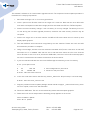
3. Hardware Reference
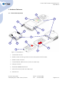
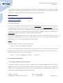
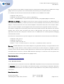
3.1. Triskan TS8 Components
10
11
1
6
3
7
13
4
2
12
15
14
8
5
9
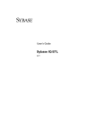
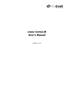
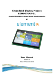
Figure 1. TriskanTS8 components.
1.
Triskan TS8 main unit
2.
Reader module containing 1D laser scanner and optional HF RFID reader
3.
Reader module connector
4.
Triskan TS8 Mini-USB connector (under the rubber flap)
5.
Charger connector
6.
Removable GSM/WLAN antenna
7.
Micro-SD card slot (under the rubber flap)
8.
SIM card slot
© Artec Group, 2010
Teaduspargi 6/2, 12618, Tallinn, Estonia
Phone: +372 671 8550
Fax:
+372 671 8555
Page 8 of 47
Triskan TS8 Firmware Development Kit
User Manual
9.
Reset pin hole
10. Keypad
11. Indicator LEDs
12. Battery pack
13. Triskan TS8 development adapter
14. Development console mini-USB connector
15. Boot mode selection header
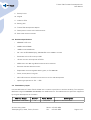
3.2. Hardware Specifications
•
ARM926EJ CPU core
•
32MB mobile SDRAM
•
16MB on-board NOR flash
•
2.8'' color OLED QVGA display, 320x240 65K colors 10000:1 contrast
•
Removable micro-SD card up to 2GB
•
1D laser scanner with optional HF RFID
•
GPRS class 10 or 802.11g WLAN communication modules
•
Bluetooth 2.0 base band controller
•
Replaceable and rechargeable battery pack, Li-Pol 2000mAh
•
Dome, sealed, back-lit keypad
•
Mini-USB connector with device interface for service and development
•
Operating temperatures -5C — +55C
3.3. Flash Memory Layout
Internal NOR flash of Triskan TS8 is divided into a number of partitions to achieve flexibility. The complete
NOR flash range is 0x00000000-0x01000000, with 16MB total size. The table below lists partitions supported
by the given development kit firmware.
Address Range
Blocks*
Flash Device
0x00000000-0x00020000
1:0
/dev/mtd1
© Artec Group, 2010
Teaduspargi 6/2, 12618, Tallinn, Estonia
Description
Contains U-boot bootloader
Phone: +372 671 8550
Fax:
+372 671 8555
Page 9 of 47
Triskan TS8 Firmware Development Kit
User Manual
Address Range
Blocks*
Flash Device
Description
0x00020000-0x00040000
1:1
/dev/mtd2
Contains U-boot configuration block
0x00040000-0x00080000
1:2-3
/dev/mtd3
Contains splash graphics in raw format
0x00080000-0x00200000
1:4-15
/dev/mtd4
Accommodates Linux kernel
0x00200000-0x00F60000
1:16-122
/dev/mtd5
Contains JFFS2 root file system
0x00F60000-0x01000000
1:123-127
/dev/mtd6
Contains JFFS2 configuration file system
* The “Blocks” field identifies flash memory blocks allocated for the given partitions, in U-boot format. The
first number identifies the flash chip. Each block is 128KB.
© Artec Group, 2010
Teaduspargi 6/2, 12618, Tallinn, Estonia
Phone: +372 671 8550
Fax:
+372 671 8555
Page 10 of 47
Triskan TS8 Firmware Development Kit
User Manual
4. Installing Development Tools
This section describes the process of installing Triskan TS8 firmware development tools to the host
machine. The host machine must be running a stable GNU/Linux distribution, e. g. Debian Etch or Ubuntu
either on physical hardware or in a virtual machine environment. The virtual machine known to work is
from VMWare. Other virtualization software (e. g. VirtualBox) might have unexpected issues, especially
regarding the USB connectivity.
The main development tool is the ARM cross-compiler toolchain supplied by CodeSourcery. The toolchain
is used to compile the target firmware, applications and utilities on the host machine. The libraries
supplied by the toolchain, e. g. libc, are also used to build the target root filesystem.
The development environment is complemented by the widely popular Eclipse IDE. In the scope of the given
development kit, Eclipse CDT is used to edit and build the application source code.
Root access on the development machine is not strictly required, but it may be still needed if the tools are
installed outside of the user home directory. Root access is required to install maintenance tools and
establishing necessary symbolic links if any of them is missing.
4.1. Installing Cross-Compiler Toolchain
This development kit uses arm-2010q1-202-arm-none-linux-gnueabi release of the GNU ARM crosscompiler. It is strongly recommended to use the above version since other versions require additional
modifications in the development tree. The toolchain can be downloaded from the official CodeSourcery
site at http://www.codesourcery.com/gnu_toolchains/arm under GPL/LGPL license. The toolchain installer
is also provided on the development kit DVD.
Extract the toolchain from the archive file located on development kit DVD to /opt/arm-2010q1.
$ tar -jxvf /media/cdrom/tools/arm-2010q1-202-arm-none-linux-gnueabi-i686-pc-linuxgnu.tar.bz2 -C /opt
Create symbolic links for the cross compiler. We create symbolic links with compiler name in it to allow
setting up multiple different compiler versions for different projects. To do that, execute the following
commands as root user:
$ cd /usr/local/bin
$ for I in /opt/arm-2010q1/bin/* ; \
do ln -s $I
`basename $I | sed 's/gnueabi/gnueabi2010q1/'` ; \
done
© Artec Group, 2010
Teaduspargi 6/2, 12618, Tallinn, Estonia
Phone: +372 671 8550
Fax:
+372 671 8555
Page 11 of 47
Triskan TS8 Firmware Development Kit
User Manual
After installation is complete, make sure the cross-compiler is registered correctly in the environment
variables. In a terminal, check the reported version:
$ arm-none-linux-gnueabi2010q1-gcc –version
arm-none-linux-gnueabi2010q1-gcc (Sourcery G++ Lite 2010q1-202) 4.4.1
4.2. Installing distCC distributed compiler servers (optional)
You can use distCC to accelerate the build process by running it in parallel on multiple build hosts. For
example, if multiple developers are working on the project, they can share their CPU power with each other
to accelerate the build and benefit from the other idle machines. As an alternative, you can run specialized
build servers to further speed up the build process.
To take advantage of distCC, all machines participating in the build process must have distCC server and
the cross-compiler toolchain installed. The machine(s) that coordinates the build, must have distCC client
side configuration installed as well as the distCC server.
Installing distCC is optional; without it the build process is performed on local machine only. For example,
the full build process on AMD Athlon64 3400 machine takes approximately 15 minutes. When adding a
Core2 Quad and a Core2 Duo machine for compilation and using the localhost only for decompressing and
preprocessing, it completes in less than 4 minutes.
4.2.1. Installing distCC server
DistCC daemon is run as distCC user or as nobody if distCC user is not present. It is listening for
compilation requests on a TCP socket. Client connects to distCC build server and uploads the preprocessed
code to be compiled and the command line to compile it. DistCC server executes the compiler and does the
compilation, after that the resulting binary is uploaded back to first host. All the build hosts must have the
exact same compilers installed at the same locations. To support multiple compilers, we insert the
compiler version to the compiler executable name in the symbolic link we create (e. g. arm-none-linuxgnueabi2010q1-gcc). The symbolic links are created in /usr/local/bin, where distCC can reach them.
First, install cross compiler toolchain as described in 4.1. Install the distCC package from distribution
repository (as root):
$ apt-get install distcc
Edit the /etc/default/distcc file to match your network setup, i. e. (substitute 10.0.0.0/8 with your LAN
network subnet):
© Artec Group, 2010
Teaduspargi 6/2, 12618, Tallinn, Estonia
Phone: +372 671 8550
Fax:
+372 671 8555
Page 12 of 47
Triskan TS8 Firmware Development Kit
User Manual
STARTDISTCC="true"
ALLOWEDNETS="127.0.0.1 10.0.0.0/8"
LISTENER=""
Restart the distcc:
/etc/init.d/distcc restart
4.2.2. Installing the distCC client configuration
All distCC clients should have distCC server installed as described in 4.2.1. To have the compilation job
performed by distCC, distCC must be called instead of the real compiler. This is performed by creating
another set of symbolic links in /opt/distcc and setting them only to your user PATH. DistCC picks up the
executable (symbolic link) name it is called as and executes the real compiler with the same name. As the
compilation is performed as distcc/nobody user, that user does not have /opt/distcc in the PATH and the
real compiler link is executed from /usr/local/bin on one of the build machines.
To set up the distCC client, create the distcc symbolic links:
$ mkdir /opt/distcc
$ cd /opt/distcc
$ ln -s /usr/bin/distcc arm-none-linux-gnueabi2010q1-gcc
$ ln -s /usr/bin/distcc arm-none-linux-gnueabi2010q1-g++
Configure your user PATH to reach distCC before the real compiler – append to the end of ~/.bashrc file in
your home directory:
## distcc
export PATH="/opt/distcc:${PATH}"
Create your distcc configuration file(~/.distcc/hosts) to specify which machines to use for compilation:
host1/5
host2/3
localhost/1
This file specifies the names of hosts to be used for distributed compilation. The number at the end is the
maximal number of concurrent jobs to be submitted to that host, it should be set 1 more than the number
of CPUs on remote hosts. The list is in priority order. As your machine is busy doing all the archive
extracting, configuring and preprocessing, its priority should not be very high; you might trying removing it
from the list at all.
© Artec Group, 2010
Teaduspargi 6/2, 12618, Tallinn, Estonia
Phone: +372 671 8550
Fax:
+372 671 8555
Page 13 of 47
Triskan TS8 Firmware Development Kit
User Manual
To benefit from parallel compilation, you should run from now on make commands with -jX switch; X is the
number of processes launched in parallel. This should usually be equal to the sum of processes defined in
your distCC configuration file. Prefix the make command with “time” and experiment with different
configurations to find the most optimal one.
To monitor distCC, run the following command in a separate terminal window:
$ distccmon-text 1
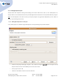
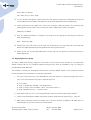
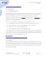
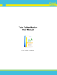
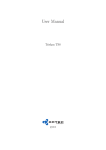
Compile your project (with make -jX flag) and observe the allocation of jobs over build hosts. If using
Eclipse, set in project properties the C/C++ build → Behaviour → Use Parallel Build option and the number
of jobs as shown in the following image:
4.3. Installing Maintenance Tools
A number of tools and libraries are required to be installed on the host machine in order to build the target
firmware correctly. The required tools and libraries are typically available as packages for your GNU/Linux
distribution. Listed below are the equivalent Debian packages.
•
netpbm – required to convert bootloader splash graphics
•
mtd-tools – required to build JFFS2 filesystem on host
© Artec Group, 2010
Teaduspargi 6/2, 12618, Tallinn, Estonia
Phone: +372 671 8550
Fax:
+372 671 8555
Page 14 of 47
Triskan TS8 Firmware Development Kit
User Manual
•
patch – required to apply patches to the source tree
•
libncurses5-dev – required by Linux kernel menuconfig (optional)
•
sharutils – required for transferring files from host system to target device using uuencode
(optional)
Install the required tools and libraries by executing:
$ sudo apt-get install netpbm mtd-tools patch
4.4. Installing Eclipse CDT
Extract the Eclipse CDT package from the development kit DVD to any suitable directory on your host
machine.
$ cd /your/path
$ tar -zxvf /media/cdrom/tools/eclipse-cpp-helios-SR1-linux-gtk.tar.gz
If your host machine does not have Java runtime environment, please install it either from a package of the
OS distribution repository, or directly from Oracle website: http://java.sun.com/javase/downloads.
Use Oracle Java as other Java implementations might cause unexpected problems.
Run Eclipse IDE either from console or by means of a custom shortcut.
© Artec Group, 2010
Teaduspargi 6/2, 12618, Tallinn, Estonia
Phone: +372 671 8550
Fax:
+372 671 8555
Page 15 of 47
Triskan TS8 Firmware Development Kit
User Manual
5. Creating Development Tree
The development tree contains source code and binary files required to build firmware and applications for
Triskan TS8 mobile data terminal. The development tree may be used to build complete firmware images
for device update and recovery, as well as application and library binaries separately.
For a complete overview of the files contained on the FDK DVD and the location of the development files
refer to 2.1.
5.1. Installing Firmware Build Tree
Unpack the development source tree from the development kit DVD to a suitable directory on your host
machine.
$ cd /homr/user
$ tar -zxvf /media/cdrom/source/ts8-fdk-rev02.tar.gz
The development source tree is organized in subdirectories that contain various parts of the target
firmware, e. g. kernel, busybox, applications. Certain directories contain README files that provide detailed
technical information about the building process or directory contents. Please refer to section 6 for details
about the tree structure.
The default location of the firmware build tree is further assumed to be /home/user/ts8-fdk.
5.2. Installing External Dependencies
In order to build valid firmware images, the external directory of the build tree must contain a number of
dependency files, as listed in Appendix A: Auxiliary Files. Binary files are not included in the development
source tree archive and must be copied manually.
$ cd /home/user/ts8-fdk
$ tar -zxvf /media/cdrom/external/external.tar.gz
Platform build scripts will automatically extract the auxiliary archives from external directory during the
building process and compile them when needed.
5.3. Doing Initial Build
Before the individual project can be managed, the firmware should be initially built. This extracts the
kernel and creates the building environment so that all the dependencies can be properly resolved. Doing
the initial build also confirms that the compiler (and optionally distCC) works properly.
© Artec Group, 2010
Teaduspargi 6/2, 12618, Tallinn, Estonia
Phone: +372 671 8550
Fax:
+372 671 8555
Page 16 of 47
Triskan TS8 Firmware Development Kit
User Manual
To build the firmware simply execute make command (with optional -j X for parallel make) in the root of the
development tree:
$ cd /home/user/ts8-fdk
$ make
Note that building the firmware from scratch takes some time. During the build process the kernel and
libraries are automatically extracted, placed into proper locations. Patches will be applied and the software
will be compiled automatically. Also the custom root filesystem will be generated and populated with
binaries necessary to run the firmware on the target machine.
For the detailed description of the building process and development tree structure please refer to section
6 of this document.
© Artec Group, 2010
Teaduspargi 6/2, 12618, Tallinn, Estonia
Phone: +372 671 8550
Fax:
+372 671 8555
Page 17 of 47
Triskan TS8 Firmware Development Kit
User Manual
5.4. Creating Eclipse Projects
Eclipse CDT IDE simplifies editing and building the Triskan TS8 source code. In this development kit,
Eclipse CDT is recommended to build the provided applications and libraries via separate Makefile projects.
NB! If the development tree was not built yet, Eclipse projects may generate dependency errors. Refer to
section 6 for building instructions.
5.4.1. Adding Development Tree Project
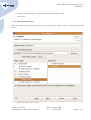
First, add a project for a whole target development tree by following the procedure below:
•
Create a new project with type "Project". File → New → Project. Do NOT use "C Project" as the
Eclipse indexer will be overloaded by the kernel source code.
•
Enter project name: ts8.
•
Uncheck "Use default location" and click Browse.
© Artec Group, 2010
Teaduspargi 6/2, 12618, Tallinn, Estonia
Phone: +372 671 8550
Fax:
+372 671 8555
Page 18 of 47
Triskan TS8 Firmware Development Kit
User Manual
•
Find your FDK source tree, e. g. go to /home/user/ts8-fdk and click OK.
•
Click Finish.
5.4.2. Adding libspatha Project
Next, add libspatha library to Eclipse projects. For this purpose, create a new C++ project as described
below.
•
Select File → New → C++ Project.
© Artec Group, 2010
Teaduspargi 6/2, 12618, Tallinn, Estonia
Phone: +372 671 8550
Fax:
+372 671 8555
Page 19 of 47
Triskan TS8 Firmware Development Kit
User Manual
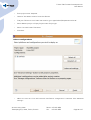
•
Enter project name: libspatha.
•
Uncheck "Use default location" and click Browse.
•
Find your FDK source tree. Under that location, go to applications/libspatha and click OK.
•
Select Makefile project → Empty Project under Project type.
•
Select Linux GCC under Toolchains.
•
Click Next.
•
Make sure that the Linux GCC toolchain and Default configuration is selected. Click Advanced
settings...
© Artec Group, 2010
Teaduspargi 6/2, 12618, Tallinn, Estonia
Phone: +372 671 8550
Fax:
+372 671 8555
Page 20 of 47
Triskan TS8 Firmware Development Kit
User Manual
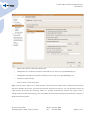
•
Select C/C++ Build → Discovery options tab.
•
Change GCC C++ Compiler invocation command to arm-none-linux-gnueabi2010q1-g++.
•
Change GCC C Compiler invocation command to arm-none-linux-gnueabi2010q1-gcc.
•
Click OK to close settings.
•
Click Finish to create the project.
Right-click on project and click on "Clean project". This executes a "make clean" command on the project
and then rebuilds the project; this also synchronizes Eclipse environment. You can build the system by
right-clicking the project and selecting "Build all". Eclipse automatically rebuilds the project when a
change is saved to disk. Alternatively, you can disable the automatic building by unchecking the Project →
Build automatically option.
© Artec Group, 2010
Teaduspargi 6/2, 12618, Tallinn, Estonia
Phone: +372 671 8550
Fax:
+372 671 8555
Page 21 of 47
Triskan TS8 Firmware Development Kit
User Manual
5.4.3. Adding Other Projects
Finally, add the demo application to Eclipse projects. You may also add libexynth, libexynthoo libraries, if
required. Follow the same procedure as for libspatha project.
•
Data collector demo application: (C++ project) ts8-fdk/applications/dataCollector
•
Simple demo slideshow: (C++ project) ts8-fdk/applications/demoApp
•
Ticket verify demo: (C++ project) ts8-fdk/applications/ticketDemo
•
libexynth library: (C project) ts8-fdk/applications/libexynth
•
libexynthoo library: (C++ project) ts8-fdk/applications/libexynthoo
It is also possible to create Managed Build C/C++ projects in Eclipse CDT for user applications and
configure them to use the ARM cross-compiler. However, managed build projects require integration into
the development tree via Makefile all and install targets. Managed build projects are not discussed in the
scope of the current version of this document.
© Artec Group, 2010
Teaduspargi 6/2, 12618, Tallinn, Estonia
Phone: +372 671 8550
Fax:
+372 671 8555
Page 22 of 47
Triskan TS8 Firmware Development Kit
User Manual
6. Building Target Firmware
Before the target firmware may be built in a newly deployed development tree, the external directory must
contain files listed in the Appendix A. Refer to section 5.2 for installation procedure.
The table below describes the directory structure of the development source tree.
Location
Description
applications
Contains applications and libraries required to support them.
applications/demoApp
Contains a sample GUI application.
applications/ticketDemo
Contains a sample ticket demo application.
applications/dataCollector
Contains a sample data collector demo application.
applications/libspatha
Contains a Triskan TS8 hardware support library.
applications/libexynth
Contains an embedded GUI engine.
applications/libexynthoo
Contains a C++ skinnable GUI support library for Xynth engine.
applications/utils
Contains various utilities used by the target device.
bootsplash
Contains utilities required to prepare the bootloader splash image.
busybox
Contains Busybox configuration and patches for the given platform, also
accommodates unpacked Busybox source.
external
Contains auxiliary archives and binary images.
fs_build
Accommodates a build filesystem, with unstripped libraries and headers.
This directory is created and filled by the building process.
fs_dist
Accommodates a release filesystem with stripped binaries. This directory
directly reflects the target root filesystem. This directory is crated and
filled during the build process.
fs_template
Contains the original template of the target filesystem. The contents is
copied to the fs_dist/ directory and populated with compiled binaries
during a building process.
kernel
Contains board source files, board specific drivers, kernel patches and
also accommodates an unpacked Linux source tree.
mkdistimage
Contains image building utilities
mksysroot
Contains an installer script for prebuilt tools and libraries taken from a
cross-compiler toolchain.
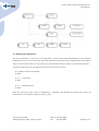
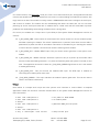
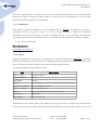
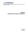
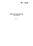
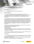
6.1. Firmware Build Flow
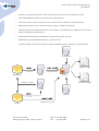
The diagram below illustrates the Triskan TS8 firmware image building sequence, as performed by
Makefile scripts of given development tree.
•
Template filesystem is created from fs_template directory. The files are installed to fs_dist.
© Artec Group, 2010
Teaduspargi 6/2, 12618, Tallinn, Estonia
Phone: +372 671 8550
Fax:
+372 671 8555
Page 23 of 47
Triskan TS8 Firmware Development Kit
User Manual
•
System root (sysroot) filesystem is built using mksysroot. The files are installed to fs_dist.
•
Kernel and Busybox are built and installed to fs_dist directory.
•
Libraries are built in their local directories. Include files are installed to fs_build directory.
•
Applications are built in their local directories, using fs_build as include path.
•
Shared libraries with debug information are installed to fs_build directory. Applications are linked
dynamically against these libraries.
•
Stripped shared libraries are installed to fs_dist directory from fs_build.
•
Applications are stripped and installed to fs_dist directory.
•
Firmware update and recovery images are generated basing on the contents of fs_dist directory.
fs_template
make
make install
.o, binary
stripped binary
Application
(local)
Update image
fs_dist
headers, libraries
Recovery image
fs_build
make
sysroot
.h, .a, .so
Library
make install
stripped binary (.so)
© Artec Group, 2010
Teaduspargi 6/2, 12618, Tallinn, Estonia
Phone: +372 671 8550
Fax:
+372 671 8555
Page 24 of 47
Triskan TS8 Firmware Development Kit
User Manual
6.2. Building Firmware Images
The directory structure of the source tree is outlined in the table above. Most subdirectories of the
development tree contain corresponding makefiles called during the firmware building process. The
Makefile and Makefile.conf scripts located in the root directory manage the complete build process and
generate firmware update image and firmware recovery image at the output.
To start building firmware images, go to the root of the development tree and execute make command.
$ cd /home/user/ts8-fdk
$ make
The make script will automatically unpack and build Busybox and Linux kernel for the target device, install
libc and other libraries from the cross-compiler toolchain, and then proceed to building applications and
utilities.
The result of the build process described above is a number of intermediate image files listed below:
File
Description
kernel/mki_zimage
Compressed kernel image.
mkdistimage/flashdisk_jffs2
NOR partition image with JFFS2 filesystem containing the root
filesystem, kernel modules, libraries and applications.
mkdistimage/confdisk_jffs2
NOR partition image with JFFS2 filesystem containing configuration files
of mobile data terminal.
The intermediate image files are further packaged into final redistributable images listed below.
File
ts8-fdk-fw.pkg
Description
Deployable firmware update package suitable for in-field upgrades using
the micro-SD memory card.
ts8-fdk-recovery.bin
Raw firmware image for NOR flash re-initialization at service locations
using a development header.
6.3. Deploying Firmware Package
To install a newly compiled firmware image on a Triskan TS8 unit with functional firmware, please copy the
ts8-fdk-fw.pkg file to the _ts8-service/ directory in the root of the micro-SD media. The destination
directory must be created if it is missing.
© Artec Group, 2010
Teaduspargi 6/2, 12618, Tallinn, Estonia
Phone: +372 671 8550
Fax:
+372 671 8555
Page 25 of 47
Triskan TS8 Firmware Development Kit
User Manual
This method is suitable for in-field firmware upgrade scenario. The complete firmware update procedure is
listed below in a step-by-step fashion.
1.
Shut down the target unit if it is currently operational.
2.
Insert a spare micro-SD flash card into the target unit's card slot. Note that the micro-SD media
must have a valid partition table and a single partition formatted with FAT16 or FAT32 filesystem.
3.
Connect an external battery charger if the unit battery is not fully charged. The battery must not
run flat during the firmware upgrade procedure, otherwise the flash memory contents may be
corrupted.
4.
Connect the target unit to the host machine via USB mini-B cable. Allow the unit to boot up and
display splash graphics.
5.
Two new USB disk drives should be recognized by the host machine. Please wait until the USB
drive detection procedure is complete.
6.
Using a file manager, browse to the last detected removable drive (further referred to as ts8-usd)
and make sure it is readable. Note that the size of ts8-usd must match the size of the inserted
micro-SD card. In case of an error, disconnect USB cable, remove the micro-SD card and prepare
the card in a stand-alone card reader connected to the host machine.
7.
If your host machine OS does not mount the USB storage automatically, mount it manually.
$ cat /proc/partitions
...
8
32
640 sdc
8
48
122959 sdd
# TS8 configuration partition
# TS8 micro-SD partition
$ mount /dev/sdd /mnt/ts8-usd
8.
In the root of ts8-usd create a new directory named _ts8-service. Skip this step if it exists already.
$ mkdir /mnt/ts8-usd/_ts8-service
9.
Copy the provided firmware update package named ts8-fdk-fw.pkg to _ts8-service directory. After
the file is copied, unmount the ts8-usd media.
10. Disconnect USB cable. The unit must automatically reboot and show splash graphics.
11. Please wait until the unit beeps and the following prompt appears on the screen.
Found firmware update
Press OK to update
© Artec Group, 2010
Teaduspargi 6/2, 12618, Tallinn, Estonia
Phone: +372 671 8550
Fax:
+372 671 8555
Page 26 of 47
Triskan TS8 Firmware Development Kit
User Manual
Press DEL to delete
Any other key to shut down
12. If such text does not appear, please make sure that previous steps were completed correctly and
the provided firmware update is designed for the Triskan TS8 development kit application.
13. Press OK button on the target unit to start the firmware update procedure. The following text
should appear on the screen. The unit will also report update status while in progress.
Updating firmware...
14. After the update procedure is complete, the target unit will display the following text and shut
down automatically.
Done. Shutting down.
15. Remove the micro-SD card from the card slot. Alternatively, you may keep the card inside and
delete the update package by pressing DEL button during the next boot.
16. Power up the unit by pressing SCAN button. Check that the unit boots up normally and starts a
demo application.
6.4. Deploying Recovery Image
To install a NOR flash recovery image on a functional or non-functional (due to blank or corrupted flash
media) Triskan TS8 unit, the compiled ts8-fdk-recovery.bin file must be uploaded to the unit using the
provided Atmel SAM-BA utility.
This method is suitable for development and service firmware update scenario. The complete firmware
recovery procedure is listed below in a step-by-step fashion.
1.
Go to the install directory of the development tree and install the required configuration files to
your Linux host machine. This step is required only once.
$ cd install
$ sudo cp modprobe.d/atmel /etc/modprobe.d
$ sudo cp udev_rules.d/atmel.rules /etc/udev/rules.d
$ sudo udevadm control --reload-rules
2.
Shut down target unit if it is currently operational, remove the battery and reader module
3.
Connect the development adapter and install the boot mode selection jumper (Fig. 1, item 15).
4.
With battery removed, connect the target unit to the host machine via USB mini-B cable. The unit
should power-up, but the screen must remain blank.
© Artec Group, 2010
Teaduspargi 6/2, 12618, Tallinn, Estonia
Phone: +372 671 8550
Fax:
+372 671 8555
Page 27 of 47
Triskan TS8 Firmware Development Kit
User Manual
5.
Go to the root of the development tree and execute make install.
6.
The build system will install Atmel SAM-BA utility if it has not been previously installed, and
connect to the target unit via USB.
-I- TCL platform : Linux
-I- SAM-BA OS : linux
-I- argv 0 : /dev/ttyUSB0
7.
The build system will automatically write the ts8-fdk-recovery.bin image to the RAM of the
connected unit and launch a re-flashing procedure.
Writing image to board
Init SDRAM
Send image
-I- File size = [n] byte(s)
Start image
Done
8.
After the SAM-BA utility terminates, Triskan TS8 unit will proceed to erasing and writing NOR
flash. The procedure may take a couple of minutes. The unit will generate a number of beeps and
reboot automatically after a final longer beep.
9.
After the flashing procedure is complete, check that the unit boots up normally and starts a demo
application.
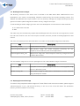
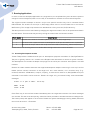
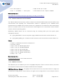
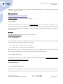
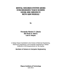
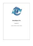
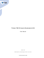
6.5. Application Linkage
The diagram below illustrates the concept of an application linkage with corresponding dependencies, as
designed by this development kit.
© Artec Group, 2010
Teaduspargi 6/2, 12618, Tallinn, Estonia
Phone: +372 671 8550
Fax:
+372 671 8555
Page 28 of 47
Triskan TS8 Firmware Development Kit
User Manual
6.6. Building User Applications
The demo application, or any other user application, may be recompiled independently of the complete
development source tree to save time. Note that applications typically require libspatha library and eXynth
engine to be built beforehand, as they make use include headers and link against corresponding libraries.
To build an application, go to an appropriate directory and execute make:
$ cd applications/libspatha
$ make
...
$ cd ../libexynth
$ make
...
$ cd ../dataCollector
$ make
Note that executing make install in dataCollector, libspatha, and libexynth directories will install the
compiled files to the target filesystem under fs_dist/.
© Artec Group, 2010
Teaduspargi 6/2, 12618, Tallinn, Estonia
Phone: +372 671 8550
Fax:
+372 671 8555
Page 29 of 47
Triskan TS8 Firmware Development Kit
User Manual
7. Running Applications
In order to launch a developed application on a target device, the compiled binary must be either copied to
a target's internal filesystem (flash or micro-SD), or accessed over network from a mounted filesystem.
The original firmware attempts to launch a script at the specific location every time it is booted without
USB attached. The location of the script is /bin/runapp, which refers to an executable file in the internal
NOR memory. The runapp script launches the dataCollector binary from the /usr/bin directory.
The above procedure can be overridden by changing the target boot mode to one of the options described in
the table below. The boot mode may be set by writing the shell U-boot environment variable.
Boot mode
Description
0
Normal start: check for firmware update, run internal /bin/runapp script.
1
Run shell: start a system console on development serial port and await further commands.
2
Run external script: start a user script from micro-SD at /mnt/mmc/_ts8-service/startup.
Please refer to the following section for details about setting U-boot environment variables.
7.1. Accessing Development Console
Triskan TS8 provides a dedicated serial port for development purposes accessible via /dev/ttyAT0 device.
The port is typically used to run a console with a Busybox shell and allows for access to system internals.
This development kit includes an adapter that plugs into the serial port connector and exposes it via USB
interface.
Remove the reader module and attach the supplied development adapter connecting it to the 6-pin service
header and the scanner connector of the target unit. On a host machine, run a terminal utility (e. g.
minicom) and select 115200 baud, 1 stop bit, no parity, no flow control mode for a /dev/ttyUSBx serial port
emulated via the USB to serial converter. Restart the target unit, you should initially receive bootloader
messages.
U-Boot 1.1.5 (Nov 27 2008 - 18:24:39)
DRAM:
32 MB
Flash: 16 MB
...
Press Enter key in the terminal window immediately after the target boots and the first U-boot messages
are received. This has to be done quickly, otherwise U-boot proceeds to autoboot and starts loading kernel.
The U-boot prompt will appear in the terminal. Disable the system watchdog by entering wdtdis, otherwise
the unit will be reset in ~15 seconds.
© Artec Group, 2010
Teaduspargi 6/2, 12618, Tallinn, Estonia
Phone: +372 671 8550
Fax:
+372 671 8555
Page 30 of 47
Triskan TS8 Firmware Development Kit
User Manual
Hit any key to stop autoboot:
0
> wdtdis
In terminal U-boot console, enter the following commands to enable a system console on the development
serial port.
> setenv shell 1
> saveenv
Saving Environment to Flash...
...
. done
Protected 1 sectors
Power-cycle the target unit, you should see the console prompt in the terminal window.
BusyBox v1.14.3 (2010-02-12 10:30:00 EET) built-in shell (ash)
Enter 'help' for a list of built-in commands.
/ #
When activated, the console provides access to available Busybox commands and compiled applications
that are integrated into the firmware. For example, the demo application may be launched as follows:
# /usr/bin/dataCollector
The U-boot environment libraries may be also read and written via OS shell commands, as shown below.
# ugetenv shell
1
# usetenv shell 0
Unlocking flash...
...
U-boot variable 'shell' is set to [0]
7.2. Transferring Files to Target
7.2.1. Internal micro-SD media
•
Power down the Triskan TS8 unit
•
Plug USB cable in and wait until the splash graphics appears on the screen.
•
Mount the last detected USB mass storage device on your development host. The mounted
filesystem is located on micro-SD media of the target device.
•
Copy the compiled applications and data files to the micro-SD media.
© Artec Group, 2010
Teaduspargi 6/2, 12618, Tallinn, Estonia
Phone: +372 671 8550
Fax:
+372 671 8555
Page 31 of 47
Triskan TS8 Firmware Development Kit
User Manual
•
If running in shell=2 mode, you can create a startup script in the root of the micro-SD media. For
example, the script below will start the dataCollector application from micro-SD when the device
boots.
#!/bin/sh
echo “Running application from MMC/SD”
/mnt/mmc/dataCollector
•
Unmount the media and disconnect the cable. The device will shut down automatically. Start it
again to test the new setup.
7.2.2. Internal NOR flash
An attached development adapter is required to access an integrated debugging console to install binaries
to the internal NOR flash. If prepared files are located on the micro-SD media, you can use the following
commands to copy them to the NOR flash memory.
# mount -t vfat /dev/mmcblk0p1 /mnt/mmc
# mount -o remount,rw /
# cp /mnt/mmc/sample/executable /usr/bin/
# cp /mnt/mmc/sample/data /usr/share/sample/
# mount -o remount,ro /
Note that mounting MMC/SD and remounting the root filesystem as read/write is not necessary if those
steps were completed before.
If the files are located on the host system, you can use the serial link to transfer them. In an example
below, the integrated Busybox uudecode utility is used to receive the file on the target device.
On target device, execute:
# cd /tmp
# uudecode
On host system, execute:
$ uuencode source.file target.file >/dev/ttyUSB0
(replace ttyUSB0 with your development adapter port name)
7.2.3. External NFS drive
An attached development adapter is required to access an integrated debugging console to mount a shared
filesystem from the development host over the USB network interface (Fig. 1, item 4). The USB stack of a
© Artec Group, 2010
Teaduspargi 6/2, 12618, Tallinn, Estonia
Phone: +372 671 8550
Fax:
+372 671 8555
Page 32 of 47
Triskan TS8 Firmware Development Kit
User Manual
target device must be first initialized to function as a network interface. For this purpose, insert the
following kernel modules into the kernel of the target device:
# modprobe at91_udc.ko
# dmesg
udc: at91_udc version 3 May 2006
# modprobe g_ether.ko
# dmesg
g_ether gadget: using random self ethernet address
usb0: MAC <MAC_ADDRESS>
Please check using dmesg that the host machine has correctly identified a new USB device, which results
in the “CDC Ethernet” profile usage. After USB network interfaces have been successfully created on both
target and host systems, assign IP addresses:
On target device, execute:
# ifconfig usb0 10.254.0.1
On host system, execute:
$ sudo ifconfig usb0 up 10.254.254.254 netmask 255.255.0.0
Finally, after the TCP/IP setup is complete, mount a remote NFS share on the target device:
# mount -t nfs -o nolock,nfsvers=2
10.254.254.254:/home/user/ts8-fdk
/mnt/nfs
After mount succeeds, the remote filesystem will be available under /mnt/nfs. Note that the host system
must export the /home/user/ts8-fdk directory as an NFS share. For more information on Linux file sharing,
please refer to the NFS howto.
7.3. Debugging via GDB
7.3.1. gdb – the GNU debugger
GDB may be used for remote debugging of applications that run on a target device. The following example
illustrates debugging of a demo application on remote target with gdb running on the host machine. On the
host machine, enter the following commands to run ARM gdb.
$ cd applications/dataCollector
$ arm-none-linux-gnueabi2010q1-gdb dataCollector
(gdb) target remote 10.254.0.1:12345
Remote debugging using 10.254.0.1:12345
0x0000abcd in _start ()
© Artec Group, 2010
Teaduspargi 6/2, 12618, Tallinn, Estonia
Phone: +372 671 8550
Fax:
+372 671 8555
Page 33 of 47
Triskan TS8 Firmware Development Kit
User Manual
(gdb) continue
Continuing.
7.3.2. gdbserver – the remote server for the GNU debugger
Gdbserver should be manually started on the target device. It requires shared versions the same libpthread
and libthread_db libraries that were used for building the application binary, in case if the latter is linked
statically. The versions must match exactly, otherwise errors and SIG32 interrupts are reported and
debugging of threaded applications is not possible. Current firmware development kit installs both
gdbserver and libraries from the cross-compiler toolchain to the target root filesystem.
To start gdbserver on the target, enter
# gdbserver localhost:12345 /path/to/application
It is convenient if the application binary is located on a network share, in such case there is no need to
transfer it to the target system every time.
Alternatively, gdbserver may be started in a multi-process mode. In such case, gdb running on host may
take advantage of remote put command to transfer the application and set remote exec-file to select the
application to run.
# gdbserver --multi localhost:12345
7.4. Resetting Target Device
The unit may be reset in hardware at an arbitrary time by inserting a steel rod into the provided reset hole
located under the battery near the SIM card slot (see Figure. 1). CPU is reset and the system will reboot.
© Artec Group, 2010
Teaduspargi 6/2, 12618, Tallinn, Estonia
Phone: +372 671 8550
Fax:
+372 671 8555
Page 34 of 47
Triskan TS8 Firmware Development Kit
User Manual
8. Developing Applications
This section refers to system interfaces and API required to develop a user application for Triskan TS8
mobile data terminal.
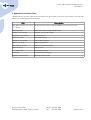
The following table contains a list of related files and directories on the provided DVD.
Name
Description
doc/
Contains development kit documentation
– libspatha-doc.tar.gz
Package containing documentation for libspatha library
– libexynthoo-doc.tar.gz
Package containing documentation for eXynth Objects library
In order to simplify the application development process, Artec provides a hardware support library called
libspatha. The library documentation is available separately, located on the FDK DVD and packaged in
libspatha-doc.tar.gz. Libspatha library encapsulates a number of C++ classes that support most of the
hardware interfaces available to Triskan TS8 applications. The library source code is provided under the
LGPL license and is located under applications/libspatha/ within the main firmware build tree.
8.1. Storage Media
8.1.1. NOR Flash
Nor flash is available as MTD device. Use mtdparts command line option to specify partition start
addresses and lengths. The flash can be accessed via /dev/mtdX as character device or via /dev/mtdblockX
as a block device via mtdblock flash to block device wrapper (where X is partitions number). Refer to the
Flash Memory Layout section for more information on available flash partitions. Usage of a regular readwrite filesystem on mtdblock device is discouraged as it will wear out the flash very fast with unoptimized
access patterns.
For NOR flashes, there are no bad blocks on new flash chips and the flash blocks will last for a number of
writes. For a rarely written partition (i. e. bootloader, kernel), the data can reside on the partition itself and
no bad block handling is needed.
Usage:
For raw flash access without bad block handling use /dev/mtdX interfaces. The utility flash_erase or
flash_eraseall has to be used to erase the corresponding flash area before writing to it. Flash area can be
read and written like a regular character device (i. e. with dd utility).
© Artec Group, 2010
Teaduspargi 6/2, 12618, Tallinn, Estonia
Phone: +372 671 8550
Fax:
+372 671 8555
Page 35 of 47
Triskan TS8 Firmware Development Kit
User Manual
For filesystems (especially read-write filesystems), usage of JFFS2 file system is encouraged. The JFFS2
shuffles blocks of data and evenly distributes the writes across the whole partition. This prevents wearing
out some more frequently written areas of the flash (i. e. FAT table locations).
More information:
http://www.linux-mtd.infradead.org/faq/general.html
http://sourceware.org/jffs2/
8.1.2. Micro-SD Card
The SD card is available to userspace applications from /dev/mmcblk0 interface as a regular block device.
If partition table exists on the SD card, the partitions are available as /dev/mmcblk0pX (where X is
partitions number). All SD cards are shipped with a partition table and one FAT partition having the whole
card space. A card can be formatted without partition table, if needed (creating FAT filesystem on
/dev/mmcblk0). Leaving the card as-is would be recommended, though.
The card can be swapped while the device is running. Indeed, the card should be unmounted first. The card
must not be swapped while the device is in sleep state, the device can not detect card change then;
buffered data from first card may be applied to the second card.
Usage:
Mount your card to a mount point using vfat filesystem:
# mount -t vfat /dev/mmcblk0p1 /mnt/mmc
Do not leave the FAT filesystem mounted read-write mode while you are not using the file system as some
changes may be buffered and not written back to card before unmounting the file system. Remount the
filesystem as read-only if it is not used for writing:
# mount -t vfat /dev/mmcblk0p1 /mnt/mmc -o remount,ro
8.2. Communication Interfaces
8.2.1. TS8-G11 GPRS Communication Module
The TS8-G11 GPRS communication module incorporates a Telit GE864 GSM/GPRS modem and uses
USART1 serial port as its data communication and some extra GPIO pins as control lines. In addition, the
system power management driver should be used to tristate (high-z) the USART when the device is
powered down, otherwise power will leak via USART lines.
© Artec Group, 2010
Teaduspargi 6/2, 12618, Tallinn, Estonia
Phone: +372 671 8550
Fax:
+372 671 8555
Page 36 of 47
Triskan TS8 Firmware Development Kit
User Manual
For communication, use /dev/ttyAT1 serial port. This is a full-featured serial port, having bidirectional data
transfer and hardware flow control. Enable the flow control to avoid flooding the modems input buffer with
large amounts of data. The modem is usually used at 115200baud/sec baud rate. Configure the serial port,
and connect to modem. The modem will do autobauding and detect the baud rate. On first use after
powering up set the serial port baud rate on modem side to a fixed value with AT commands to prevent
problems with autobauding recalculating the baud rate to a wrong value.
For control, the modem has 4 output and 1 input GPIO pin (see System Power Management section for
control):
●
O_PIN_GPRS_PWR – Power switch on main board. This can be used to turn off the modem's power
and hard-resetting the modem. The switch is defaulted to on position (even when the main CPU is
powered off) to power the RTC in the modem. This switch is intended only for resetting the modem
in case it does not respond. It should not be used for switching off the modem.
●
O_PIN_GPRS_RST – Modem RESET input. This pin can be used to generate a reset pulse to the
modem.
●
O_PIN_GPRS_ON – Modem ON input. Generate a pulse on this pin to power up the modem. Note
that the U-boot bootloader generates a ~1s pulse automatically when the system is started, to save
time. The application should first check the I_PIN_GPRS_PWRGD signal state to see if the modem
is already powered up.
●
O_PIN_GPRS_DTR – This pin controls the modems DTR input. The DTR input is needed for
controlling the modems power save state.
●
I_PIN_GPRS_PWRGD – This input indicates the modem's power good state. This can be used to
check if the modem is booted up.
Usage:
Given below is a sample shell script that uses pwrctrl write interface to control GPIOs. A compiled
application should use the IOCTL interface instead. Refer to the System Power Management section for
more information.
# echo 'o05'>/dev/pwrctrl
# cut power to GPRS modem
# echo 'O05'>/dev/pwrctrl
# re-enable power
# sleep 1
# echo 'O07'>/dev/pwrctrl
# generate GPRS_ON line pulse
# sleep 1
# echo 'o07'>/dev/pwrctrl
# stty -F /dev/ttyAT1 -echo crtscts
© Artec Group, 2010
Teaduspargi 6/2, 12618, Tallinn, Estonia
# setup serial port
Phone: +372 671 8550
Fax:
+372 671 8555
Page 37 of 47
Triskan TS8 Firmware Development Kit
User Manual
# cat /dev/ttyAT1 &
# dump serial port input
# echo -e "AT+CGMR\r" > /dev/ttyAT1
# send modem version request command
More information:
http://www.telit.com/en/products/gsm-gprs.php?p_id=12&p_ac=show&p=11
8.2.2. TS8-W11 WLAN Communication Module
The TS8-W11 WLAN communication module is based on the Ralink RT3070 chipset and uses USB for data
communication and signaling. The communication module is supported by the rt3070sta driver
implemented as a loadable kernel module. The driver is supplied with this FDK and is built automatically
within the firmware build tree. The communication module appears as a conventional wireless network
interface ra0 to the operating system.
Additionally, WLAN module can be controlled using the following GPIO pins (see system power
management section):
●
O_PIN_MPCIE3VEN – controls the power supply to WLAN communication module. Default: on
●
O_PIN_WLAN_RADIO_ON – enables the radio interface of the communication module. Default: off
Usage:
# insmod /lib/modules/wireless/rt3070sta.ko
# ifconfig ra0 up
# iwpriv ra0 set NetworkType=Infra
# iwpriv ra0 set AuthMode=WPA2PSK
# iwpriv ra0 set EncrypType=AES
# iwpriv ra0 set SSID="YourNetwork"
# iwpriv ra0 set WPAPSK="NetworkKey"
# udhcpc -nR -i ra0
More information:
kernel/drivers/wireless/ in the firmware build tree
8.2.3. USB Device Interface
The USB device port is handled by the Linux usb gadget subsystem. There are various drivers, the drivers
are compiled as modules and are loaded as needed and can be swapped.
USB Mass Storage Gadget – This gadget can be used to offer one or more block devices or image files
as USB mass storage devices. These show up as regular mass storage drives on host computer and the
© Artec Group, 2010
Teaduspargi 6/2, 12618, Tallinn, Estonia
Phone: +372 671 8550
Fax:
+372 671 8555
Page 38 of 47
Triskan TS8 Firmware Development Kit
User Manual
host can copy files via the USB link. Always unmount the block device before giving it to USB mass storage
gadget driver, as file systems can not be accessed simultaneously from multiple locations.
For example, the SD card can be shared across the USB to create a USB SD card reader:
# modprobe at91_udc.ko
# modprobe g_file_storage.ko stall=0 removable=y
# echo '/dev/mmcblk0p1'>/sys/devices/platform/at91_udc/gadget/gadget-lun0/file
USB Ethernet Gadget – This gadget can be used to create a ethernet connection over USB between the
host and the device. Basically, it shows up on host as an ethernet adapter and on device also as an ethernet
adapter. It acts as these there were two ethernet adapters connected to each other with crossover cables.
The virtual ethernet adapter can be bridged on host side to allow access to physical network via the host.
This network configuration can be easily used to share files between the host and the device. All common
network tools can be used. The device can mount a NFS directory from host and run directly the
applications from the host's filesystem. The device can run a GDB server for remote application debugging
controlled from the host.
Given below is a sample shell script that configures the usb0 network interface and mounts an NFS share:
# modprobe at91_udc.ko
# modprobe g_ether.ko
# ifconfig usb0 192.168.1.2
# mount -t nfs -o nolock,nfsvers=2 192.168.1.2:/home/user/share /mnt/nfs
Warning : the MAC addresses of the network adapters are generated randomly in a range allowed for local
use. If using multiple devices in same network (ie connected to a same computer or bridged to a same
network), ensure that the random number generators on the devices are not generating same numbers to
avoid MAC address collisions or allocate MAC addresses manually (it is sufficient to set the system time
from RTC before before loading USB ethernet gadget driver).
More information:
http://www.linux-usb.org/gadget/
8.2.4. Bluetooth Interface
The bluetooth chip is connected via external 16550 UART compatible serial port chip and can be accessed
via /dev/ttyS0 serial port. The chip needs to be initialized on power-up according to its datasheet. Bluetooth
uses MAC addresses and the user needs to provide a unique address to every device during the power-up
initialization.
More information:
© Artec Group, 2010
Teaduspargi 6/2, 12618, Tallinn, Estonia
Phone: +372 671 8550
Fax:
+372 671 8555
Page 39 of 47
Triskan TS8 Firmware Development Kit
User Manual
http://www.national.com/pf/LM/LMX9830.html
8.3. Scanner Interfaces
8.3.1. TS8-RB1R0 Barcode Scanner
The TS8-RB1R0 reader module incorporates an Opticon 1D barcode laser scanner. The barcode scanner is
connected to USART2 serial port for data connection and to some GPIO pins for control. In addition, the
system power management driver is used to tristate the USART when the device is powered down.
The data port of the reader can be accessed via /dev/ttyAT2. The reader is defaulted to 9600 baud, 8N1. The
reader has its own internal configuration flash and the settings changed are stored. Be sure not to lock
yourself out when re-configuring the device!
For control, the following GPIO pins are used (see system power management section):
●
O_PIN_2D_PWR – controls the power supply to turn on/off the 2D readers power. Default: off
●
O_PIN_2D_DWNLD_N – controls the readers DWNLD# pin. Usage not documented.
●
O_PIN_2D_AIM – controls the readers AIM/WAKEUP pin.
●
I_PIN_2D_PWR_DWN – indicates the readers PWR_DWN pin state.
To read a barcode, power up the reader (set pins DWNLD_N and AIM high, then set pin PWR high), wait
until the reader powers up, issue a continuous trigger command ( <ESC>Y0<CR>), issue a trigger command
(<ESC>Z<CR>), wait for data, issue a detrigger command ( <ESC>Y<CR>), optionally power down the reader
(tristate the serial port and set pins PWR, DWNLD_N, AIM low).
More information:
http://old.opticon.com/uploads/Manual/Menubook_en.zip
8.4. User Interface
In order to simplify the graphical user interface development for Triskan TS8 applications, Artec provides
an optimized version of Xynth GUI engine and a custom GUI layout library called libexynthoo. The library
source code is provided under the LGPL license and is available under applications/libexynthoo within the
main firmware build tree. Documentation for the library is provided separately on the FDK DVD in
libexynthoo-doc.tar.gz package.
© Artec Group, 2010
Teaduspargi 6/2, 12618, Tallinn, Estonia
Phone: +372 671 8550
Fax:
+372 671 8555
Page 40 of 47
Triskan TS8 Firmware Development Kit
User Manual
The items listed below refer to a direct access to the user interface hardware of the mobile data terminal.
Direct access may be desired for smaller utilities, for performance critical applications, or for any other
case where the Xynth approach is not applicable.
8.4.1. OLED Display
OLED display is provided to application as a framebuffer device at /dev/fb0. The application can map the
framebuffer memory using that interface or use the interface directly to read/write framebuffer.
Framebuffer can even be read using usual shell commands like dd or even redirecting some command
returning standard output to framebuffer device. For example, showing gzipped raw framebuffer images:
# zcat file.gz>/dev/fb0
More information:
http://www.linux-fbdev.org/
8.4.2. Keypad
Keyboard is available as event device. An application can access the keyboard via /dev/eventX. Application
should loop through event devices and poll EVIOCGBIT command to get event types provided by that event
device. The application should find the event device providing EV_KEY support.
The following table lists the possible key codes:
Key
Description
KEY_0 .. KEY_9
Numeric keys 0..9
KEY_BACKSPACE
DEL key
KEY_ENTER
OK key
KEY_DOT
Key for special characters (located at the lower left corner)
KEY_UP, KEY_DOWN
UP and DOWN arrow keys
KEY_F1 .. KEY_F5
Function keys F1..F5
KEY_F11
Shift key (located at the lower right corner)
KEY_MENU
MENU key
KEY_POWER
Scan / Power key
SCAN-button is also used as power button. When connecting the device to computer via USB, the device
must power on, because of that a pulse is generated on SCAN button by rising +5V in USB connector. The
© Artec Group, 2010
Teaduspargi 6/2, 12618, Tallinn, Estonia
Phone: +372 671 8550
Fax:
+372 671 8555
Page 41 of 47
Triskan TS8 Firmware Development Kit
User Manual
application can poll the USB +5V line via system power management driver to filter out button presses
caused by plugging in the USB.
More information:
http://www.linuxjournal.com/article/6429
utils/get_keypress.c utility in the firmware build tree
8.4.3. Speaker
The speaker is available as an event device at /dev/input/eventX. This is a special case of event device, that
can control output devices. Poll EVIOCGBIT command to find event device providing EV_SND support. Send
and event with value equal to the frequency to start the speaker oscillator. Send frequency 0 to stop the
speaker oscillator.
See also:
applications/utils/sprktest.c utility in the firmware build tree
8.4.4. LED Indicators
Two LED indicators on top of the keypad are available to user applications. For control, the following GPIO
pins are used (see system power management section):
●
O_PIN_LED_R – enables the red LED indicator
●
O_PIN_LED_G – enables the green LED indicator
When the mobile terminal is connected via USB to a host, the LED outputs are driven by battery charger
circuitry. The software may then override charger outputs to enable LED indicators.
8.4.5. Ambient Light Sensor
The ambient lighting data can be read from the on-board ISL29001 sensor from /sys/devices/platform/i2cgpio/i2c-adapter:i2c-0/0-0044/illum1_input.
8.5. System Interfaces
8.5.1. CPU Power Management
Atmel AT91 SoC is capable of switching the system clock to RTT oscillator (32kHz) and stopping the fast
PLLs and main oscillator to save power. With all peripherals off and system idle, the current consumption
© Artec Group, 2010
Teaduspargi 6/2, 12618, Tallinn, Estonia
Phone: +372 671 8550
Fax:
+372 671 8555
Page 42 of 47
Triskan TS8 Firmware Development Kit
User Manual
(measured between the battery) is ~80mA when system clock is derived from the main oscillator and
~20mA when system clock is switched to RTT oscillator and the fast PLLs and main oscillator are stopped.
To go to the low power mode, write “mem” to /system/power/state.
# echo “mem” > /system/power/state
The system will wake up on either RTT (real-time timer, see below) interrupt or another configured wakeup source (for example, buttons). By default, all wake-up sources are enabled, but they can be disabled via
sysfs.
8.5.2. System Power Management
The power manager driver is used to control the system power supplies (via GPIO pins), adjust keyboard
backlight, tristate USART ports and control GPIO ports. The driver can be controlled using either ioctl or
write interfaces via /dev/pwrctrl.
IOCTL interface (unsigned long command, unsigned long argument):
IOCTL Command
PWRCTRL_SET_GPIO_HI
Argument
Description
bits 0-7: gpio out id Set GPIO output pin id high (pin id's are defined in
pwrctrl.h)
PWRCTRL_SET_GPIO_LO
bits 0-7: gpio out id Set GPIO output pin id low
PWRCTRL_GET_GPIO
bits 0-7: gpio out id Get the GPIO input pin id state
PWRCTRL_SET_KBDBL
bits 0-7: intensity
Set the keyboard backlight intensity to a defined
value
PWRCTRL_FADE_KBDBL_TO
bits 0-7: final
Fade the keyboard backlight to the selected final
intensity
intensity in 25 ms steps.
USART_TRISTATE_ON
bits 0-7: usart id
Mux the usart id pins to high-z state.
USART_TRISTATE_OFF
bits 0-7: usart id
Mux the usart id pins to USART.
Write interface (argument xx is in HEX):
Write
Description
command
Oxx
Set GPIO output pin xx high (pin id's are defined in pwrctrl.h)
oxx
Set GPIO output pin xx low
Lxx
Set the keyboard backlight intensity to xx
Axx
Fade the keyboard backlight to intensity xx in 25 ms steps
Txx
Mux the usart xx pins to high-z state.
© Artec Group, 2010
Teaduspargi 6/2, 12618, Tallinn, Estonia
Phone: +372 671 8550
Fax:
+372 671 8555
Page 43 of 47
Triskan TS8 Firmware Development Kit
User Manual
Write
Description
command
txx
Mux the usart xx pins to USART.
The write interface is intended to make easier controlling of the device from shell scripts, ie:
# echo “AFF” > /dev/pwrctrl
8.5.3. Real-Time Timer
AT91 contains a real-time timer. This timer is run from 32768Hz oscillator and it is running even while the
system is powered off. The timer counter is incremented at 1Hz and can only be read, not written. The
counter is set to 0 on connecting the battery. The RTT is capable of generating an alarm interrupt and
waking up the system from suspended state or power-down state.
The real-time timer serves mainly two purposes: keeping time while the system is in suspend and waking
up the system from suspend state at a predefined interval.
Access to the RTT timer is provided through standard Linux RTC interface.
8.5.4. Battery Voltage
There is a dedicated chip on board for reading the battery voltage. The value can be read at
/sys/devices/platform/atmel_spi.1/spi1.3/in_input0.
8.5.5. Temperature Sensor
The temperature can be read from the on-board LM75 temperature sensor from /sys/devices/platform/i2cgpio/i2c-adapter:i2c-0/0-0048/temp1_input.
© Artec Group, 2010
Teaduspargi 6/2, 12618, Tallinn, Estonia
Phone: +372 671 8550
Fax:
+372 671 8555
Page 44 of 47
Triskan TS8 Firmware Development Kit
User Manual
9. Appendix A: Auxiliary Files
Listed below are the files required for building the target firmware. The files are located in the external/
directory of the development kit build tree.
File
Description
2009_0525_RT3070_Linux_STA_ WLAN interface driver for Ralink RT3070 mini-PCI express card
v2.1.1.0.bz2
bootsplash.png
Bootloader splash image in PNG format
busybox-1.16.1.tar.bz2
BusyBox source code tarball
dosfstools-3.0.9.tar.bz2
Filesystem tools
expat-2.0.1.tar.gz
XML parser library
freetype-2.3.12.tar.bz2
Font rendering library
libpng-1.4.1.tar.gz
PNG imaging library
linux-2.6.33.3.tar.bz2
Linux kernel source tarball
ppp-2.4.5.tar.gz
PPP services
zlib-1.2.5.tar.bz2
Compression library
u-boot.bin
U-boot bootloader binary
wireless_tools.29.tar.gz
Wireless network tools
© Artec Group, 2010
Teaduspargi 6/2, 12618, Tallinn, Estonia
Phone: +372 671 8550
Fax:
+372 671 8555
Page 45 of 47
Triskan TS8 Firmware Development Kit
User Manual
10. Appendix B: Licensing
Triskan TS8 firmware development kit contains software components that are GNU GPLv2 and GNU
LGPLv2.1 licensed. A copy of these licenses are included on the FDK DVD along with the source code for all
related components.
Portions of this software are copyright © 2008 The FreeType Project (www.freetype.org).
All rights
reserved.
© Artec Group, 2010
Teaduspargi 6/2, 12618, Tallinn, Estonia
Phone: +372 671 8550
Fax:
+372 671 8555
Page 46 of 47
Triskan TS8 Firmware Development Kit
User Manual
11. Appendix C: Change log
2010-10-20:
•
Changed gcc version in example commands to 2010q1
•
Added screenshots for configuring Eclipse IDE
•
Updated developer tree to reflect the changes for moving to eXynth and eXynthoo libraries
•
Updated external program version numbers
•
Created FDK DVD layout section 2.1
•
Created additional section 5.3 describing initial build procedure
2009-12-04:
•
Fixed example gcc version query example in section 4.1
2009-06-29:
•
Added the “Required Skills” paragraph
2009-04-24:
•
Changed compiler set-up procedure to have compiler version in executable name.
•
Added distributed/parallel build instructions
© Artec Group, 2010
Teaduspargi 6/2, 12618, Tallinn, Estonia
Phone: +372 671 8550
Fax:
+372 671 8555
Page 47 of 47