1
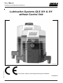
User Manual Installation and Operation Instructions Lubrication Systems QLS 301 & 311 without Control Unit Subject to modifications B-Q30 11-0 00a10 U.S. Patent-No. 6,244,387, German Registration Design No. 29923765.6 6093b0 3 810-55250-1B Form 403011 2.1EN-38009-B10 User Manual Installation and Operation Instructions This User Manual was compiled on behalf of - the manufacturer - by Lincoln GmbH EdiDoc GmbH Heinrich-Hertz-Str. 2-8 Erzberger Str. 8 D-69190 Walldorf D-68753 Waghäusel All rights reserved. Any duplication of this User Manual, in its entirety or in part, by whatever means is prohibited without the prior consent in writing of Lincoln GmbH. Subject t o modifications without prior notif ication. Subject to modifications © 2010 by Phone: +49 (6227) 33-0 Fax: +49 (6227) 33-259 E-Mail: [email protected] Page 2 of 34 2.1EN-38009-B10 Form 403011 User Manual Installation and Operation Instructions Table of Contents Page Introduction .... .............. ....................... ...................... ...... Explanat ion of Symbols Used ................ ...................... ...... User´s Responsibility ...... ....................... ...................... ...... Environmental Protection ...................... ...................... ...... Service ..... ........ .............. ....................... ...................... ...... Safety Instructions Appropriate Use ............. ....................... ...................... ...... Misuse ...... ........ .............. ....................... ...................... ...... Exclusion of Liability . ....................... ...................... ...... Regulations for Prevention of Accidents ...................... ...... General Safety Instructions ................... ...................... ...... Operation, Maintenance and Repair ...... ...................... ...... Operation/Maintenance ................... ...................... ...... Operation with bayonet plug ............ ...................... ...... Repair . ........ .............. ....................... ...................... ...... Disposal .................... ....................... ...................... ...... Installation ........ .............. ....................... ...................... ...... 4 4 4 4 4 5 5 5 5 5 5 6 6 6 6 6 Installation Instructions Pump ........ ........ .............. ....................... ...................... ...... 7 Pumps with mounted metering device ... ...................... ...... 7 Determination of the output by cross-porting of outlets .................... ...................... ...... 7 Single output ............. ....................... ...................... ...... 7 Double or multiple outputs ............... ...................... ...... 7 Closure plug .............. ....................... ...................... ...... 7 Check valve .............. ....................... ...................... ...... 7 Dirct (internal) feedback feature ............ ...................... ...... 8 Pumps with external metering device .... ...................... ...... 8 Lubrication Points ........... ....................... ...................... ...... 8 Zerk-Lock Connection .... ....................... ...................... ...... 8 Connection of Feed Lines ...................... ...................... ...... 9 First filling of a lubrication system .......... ...................... .... 10 Electrical Connection ...... ....................... ...................... .... 10 Option for metric fittings .. ....................... ...................... .... 11 Page Description ...... ...................... ...................... ............... .... 12 Identification Code VDC .................. ...................... ...................... ............... .... 14 Mode of Operati on Lubrication System ................. ...................... ............... .... 15 Pressure Relief Valve ............. ............... ....... ............... .... 15 Low-Level Control ................... ...................... ............... .... 15 Maintenance, Repair and Tests Maintenance ..... ...................... ............... ....... ............... .... To fill reservoir ................... ...................... ............... .... Repair ............... ...................... ...................... ............... .... Electrical Connection .............. ...................... ............... .... Tests ................. ...................... ...................... ............... .... 16 16 17 17 17 Troubleshooting .................... ............... ....... ............... .... 18 Technical Data Rating ............... ...................... ...................... ............... .... External Interfaces .................. ...................... ............... .... Electrical Data ... ...................... ...................... ............... .... Connecting Diagrams ........ ...................... ............... .... Dimensions ....... ...................... ...................... ............... .... 20 20 21 22 23 Service Parts and Assembly Kits .............. ............... .... 24 EC Declaration of Conformi ty ............. ....... ............... .... 33 Lincoln worldwide ................. ...................... ............... .... 34 Subject to modifications Keep this user information always at hand at the place of work of the pump! Form 403011 2.1EN-38009-B10 Page 3 of 34 User Manual Installation and Operation Instructions Introduction Explanation of Symbols Used The following description standards are used in this manual: Safety Instructions Structure of safety instructions: Pictogram Signal word Danger text - Danger not e - How to avoid danger The following pictograms are used in this manual and are combined with the corresponding signal words: 1013 A94 4 273a0 0 - ATTENTION - CAUTION - ATTENTION - CAUTION - WARNING - WARNING 6001a 02 - NOTE - IMPORTANT The signal words give the seriousness of danger if the following text is not observed: ATTENTION CAUTION WARN ING NOTE IMPORTANT refers to faults or damages on machines. refers to bad damages and possible injuries. refers to possible dangerous injuries. indicat es improved operation of the device. indicat es special operating features of the device. Example: User's Responsibility To ensure the safe operat ion of the unit, the user is responsible for the following: 1. The pump / system shall be operated only for the intended use (see next chapter "Safety Instructions") and its design shall neither be modified nor transformed. 2. The pump / system shall be operated only if it is in a proper functioning condition and if it is operated in accordance with the maintenance requirements. 3. The operating personnel must be familiar with this User Manual and the safety instructions mentioned within and observe these carefully. The correct inst allation and connection of tubes and hoses, if not specified by Lincoln GmbH, is the user's responsibility. Lincoln GmbH will gladly assist you with any questions pertaining to the installation. Environmental Protection Waste (e.g. used oil, detergents, lubricants) must be disposed of in accordance with relevant environmental regulations. Service The personnel responsible for t he handling of the pump / system must be suitably qualified. If required, Lincoln GmbH offers you full service in t he form of advice, on-site installation assistance, training, etc. We will be pleased to inform you about our possibilities to support you purposefully. In the event of inquiries pertaining t o maintenance, repairs and spare parts, we require model specific data to enable us to clearly identify the components of your pump / system. Therefore, always indicate the part, model and series number of your pump / system. Subject to modifications 10 13A94 ATTENTION! When making use of other than the tested spare parts, serious damage may affect your device. Therefore, for the operation of your device always use original parts made by Lincoln GmbH. Furthermore, you will find the following text symbols in this manual: Listing of applicable statements - Subpoint of applicable statements 1. Det ermination of the number or sequence of contents  Procedural instruction Page 4 of 34 2.1EN-38009-B10 Form 403011 User Manual Installation and Operation Instructions Safety Instructions Appropriate Use Regulations for Prevention of Accidents The lubricat ion systems QLS 301/311 has been designed for initial and retrofit installation. I t has been designed for: the automatic lubrication of machines and systems the automatic lubrication of commercial vehicles and construction machines the automatic lubrication of hydraulically driven units and devices. The lubricat ion systems QLS 301/311 is able to deliver greases up to NLGI - class 2 or fluid greases of NLGI - class 000 or 00. Use the QLS 301/311 exclusively to supply lubricants. The QLS 301/311 are adequate for intermittent operat ion only. The 301/311 are adequate for feeding max. 18 lube points per lubricating cycle. Do not use QLS 301/311 with SSV divider block in bottom mounting position for mobile applications. Do not install the system with machines exposed to shock. To prevent accidents, observe all city, state and federal safety regulations of the country in which the product will be used. Avoid the operation with - unapproved parts. - insufficient or contaminated lubricants. General Safety Instructions Misuse Any use of the QLS 301/311 that is not expressly mentioned in this User Manual will be regarded as misuse. If the QLS 301/311 are used or operated in a different manner other than specified, any claim for warranty or liability will be null and void. NOTE 6001a0 2 If personal injury or material damage occurs as a result of inappropriate operation, e. g. if the safety instruct ions are ignored or resulting from an incorrect installation of the QLS 301/311, no claims or legal actions may be taken against Lincoln GmbH. Lubrication systems QLS 301/311 - are designed state-of-the-art. - can be assembled for safe operation. - must be filled regularly without air inclusions with clean lubricant recommended by the manufacturer (see “List of Lubricants” 2.0-40001). Incorrect use may result in bearing damage caused by poor or excessive lubricat ion. Do not overpressurize reservoir when filling the pump. Refill QLS 301/311 pumps with clean lubricant. Each outlet needed must be equipped with an appropriate check valve. IMPORTANT 6001a0 2 Any modifications must be subject to prior consultation with t he manufacturer of the QLS 301/311. Operation, Repair and Maintenance ATTENTION! Malfunction because of dirt! When executing any maintenance or repair works on the QLS 301/311, ensure absolute cleanliness. Subject to modifications Exclusion of Liability The manufacturer of the centralized lubrication systems QLS 301/311 will not accept any liability for damage: Caused by insufficient lubricant - due to irregular filling of the reservoir - due to wrong programming of the internal or external controller - due to wrong planning and layout of the downstream lubricant distribution. caused by the use of contaminated lubricant s. due to the use of lubricants which are not or are only conditionally pumpable in centralized lubrication systems. caused by connection to a wrong supply power. caused by an environmentally inadequate disposal of used or contaminated lubricants or parts that were in touch with lubricants. caused by unauthorized modification of system components. caused by the use of unapproved part s (voids the pump warranty). Form 403011 Do not paint the pump! Before painting a machine or commercial vehicle, remove or cover the pump completely. 1013A94 WARNING! Before maint enance or repair of pumps switch off their power supply. 427 3a00 CAUTI ON! It is not allowed to use the pump in potentially explosive fields. 1013A94 2.1EN-38009-B10 Page 5 of 34 User Manual Installation and Operation Instructions Safety Instructions, continuation Operation/Maintenance Lincoln Quicklub centralized lubricat ion systems must be operated only with installed pressure relief valve. must be operated wit h attached or connected SSV metering device make Lincoln GmbH. must be refilled in regular intervals with clean and recommended 1) lubricant without air entrapments. 1) see recommendation of the user or the manufacturer of the machine or the vehicle & List of Lubricants (2.0-40001) operate automatically. However, a regular check (approx. every 2 days) should be made to ensure that lubricant is emerging from all lubrication points. ATTENTION! Consider residual ripple of max. ±5 % to connect pumps with direct current version (in relation to the operating voltage acc. to DIN 41755). 4273a0 0 Repair Disposal Repairs should only be performed by authorized personnel who are familiar with t he repair instructions. Dispose of used or contaminated lubricants as well as of parts that were in touch with lubricant according to the legal regulations pertaining to environmental protection. Make sure to observe the safety dat a sheets of the lubricants used. Installation Any safety equipment already f itted to the machine: - should not be modified or made ineffective; - should only be removed for the purpose of fitting the system; - must be reinstalled after fitting the system. Keep Quicklub centralized lubrication systems away from sources of heat. Adhere to the operating temperature. Use only original Lincoln spare parts (see Parts Catalog 2.0-20001) or parts approved by Lincoln. Adhere to: - the installation instructions of the machine manufacturer as regards all drilling and welding procedures. - the specified minimum distances between the boreholes and the upper/lower rim of the frame or between two boreholes.  Route supply lines professionally.  Firmly bolt together pressurized components. 6001 a02  Consider the torsion torques. NOTE 6001a0 2 In case of rear-mounted lubricant metering devices: For transporting outlet 2 of the metering device was equipped with a check valve. Make sure to remove it before assembly, as it cannot be used when operating. Subject to modifications IMPORTANT Page 6 of 34 2.1EN-38009-B10 Form 403011 User Manual Installation and Operation Instructions Installation Instructions Pump Mount pumps in such way that access is provided to refill and test the pump. Use drilling template to mark and drill mounting holes of the pump. Drilling template and mount ing bolts are included in the package. Pumps with mounted metering device Determination of the output by cross-porting of outlets 1) Single output A single output is the lubricant quantity fed to the lube point by a piston per stroke and outlet port. I t amounts to approx. 0.2 cm³, see outlet 6 (fig. 1-1). 1014 b00 Fig. 1-1 Single double and triple lubricant output (on back side mounted divider block) 0x-3x Outlet quantity (single, double, etc.) 1-6 Outlet numbers A Clamping ring of the check valve (see Fig. 3) B Grease supply C Enclosed grease R Return to reservoir 6001a0 2 NOTE Maximum internal combination of outlets: SSV 6 = 3 / SSV 12 = 6 / SSV 18 = 9 Further combinations are possible outside the metering device by means of a teepiece only. 2) Double or multiple outputs Output s can be increased by simply plugging the unused outlet ports with closure plugs (fig. 2, provided in the accessory kit). Lubricant from a plugged outlet is redirected to the next outlet on the same side of the SSV divider block in descending numerical order (see fig.1). Example, see fig. 1: By closing - of outlet 4, outlet 2 receives the double quantity - of outlets 5 and 3, outlet 1 receives the triple amount of lubricant. The connecting conduit from outlet line 1 to outlet line 2 and to the return line (R) is closed by clamping rings (A) of the check valve. Unused lubricant can be internally fed back to the reservoir, see paragraph ‘’direct internal feed back feature”. ATTENTION ! If outlet 2 (fig. 1-1) is connected to a lubrication point, outlet 1 must not be closed, see clamping ring (A) in out let 2. 6001 a02 Closure plug  Install a closure plug in each outlet port that is not required. 4163 a98 Fig. 1-2 Closure plug (also provided in the accessory kits) Check valve Subject to modifications  For connection between pressure plastic tubes or highpressure plastic hoses and SSV divider outlets.  Install a check valve in each outlet port that is required. 4180 a02 Fig. 1-3 Check valve, push-in type A Clamping ring (brass) Form 403011 2.1EN-38009-B10 Page 7 of 34 User Manual Installation and Operation Instructions Installation Instructions, continuation Direct (internal) feedback feature All pumps with back-mounted SSV metering device have the capability to feed unused lubricant back internally from closed outlets directly to the reservoir (see R, fig. 1-4). This procedure will start automatically, if outlet port 2 is plugged wit h a closure plug. For lubricant return of crossported outlets always start with the smallest outlet numbers: - Outlets with even numbering: ………… e. g. 2, 4, 6 - Outlets with odd numbering: ... ............. e. g. 1, 3, 5 Lubricant quantities of odd outlet numbers can only be returned through the internal combination of outlets 1 and 2. As shown in Fig. --4, the quantities of outlets 1, 2 and 4 (3xR) are returned to the reservoir. The remaining outlets are to be used for the connection t o the lube point or for increasing the lubricant quantity (double or triple), comp. fig. 1-1. 4188b 99 Fig. 1-4 0x-2x 1-6 A B C R ATTENTION! Internal feedback of supplied lubricant, only on back-side mounted SSV divider blocks Outlet quantity (single, double, etc.) Outlet numbers Clamping ring (brass) of the check valve Grease supply Enclosed grease Return line bore 1 013A94 Do not plug outlets number 1 or 2 (horizontally positioned outlets) on bott ommounted lubricant metering devices SSV 8, 12 or 18. In this case there exists the possibility to return unneeded lubricant quantities externally f rom the metering device. To do so, use relief line connection R. Pumps with external metering device Lubrication Points The pump can also be operated with an external metering device. To provide a directly connected lube point with lubricant or to distribute the lubricant via a downstream progressive syst em a connection block 1 (fig. 6-3) with P pressure and R return connection is provided. Installing Quickli nc fi ttings into lube points  Replace the existing lubrication fitting at the lubrication point by the corresponding Quicklinc push-in fitting. Zerk-Lock Connection Subject to modifications 6 001a02 4200a 99 Fig. 2-1 Place the Zerk-Lock body over the grease nipple Page 8 of 34 4201a 99 Fig. 2-2 Installation of ZerkLocks with staking tool NOTE I f the lubricat ion fitting cannot be replaced, t he Zerk-Lock connection is available as an alternative. The Zerk-Lock fitting consists of the Zerk-Lock body, insert and a Quicklinc fitting.  Place the Zerk-Lock body over the grease fit ting and place the staking tool firmly against the Zerk-Lock insert.  Strike the tool sharply with a hammer until the Zerk-Lock insert partially crimps onto the grease fitting (necessary only for US version). 2.1EN-38009-B10 Form 403011 User Manual Installation and Operation Instructions Installation Instructions, continuation  Screw the Quicklinc fitting into t he Zerk-Lock body and tighten until part resists further tightening (about 1-1/2 turns). NOTE Quicklinc hex. is 12 mm. Zerk-Lock body hex is 1/2 ’’. 600 1a02  Move the Zerk-Lock and tube fitt ing from side to side on the grease fitting to insure the Zerk-Lock is firmly seated. 420 2a99 Fig. 2-3 Screwing Quicklinc fitting into the Zerk-Lock body Connection of Feed Lines  Lay feed lines to each lubrication point with the shortest possible route. Make sure to observe the minimum bending radius.  Measure, cut and route the feed lines (included in the kit). NOTE 60 01a02 4 203a99 Fig. 3-1 Feed line installed in the Quicklinc fitting Avoid sharp bends of the plastic tubing and the moving parts of the machine that could damage the lubrication lines. Minimum bending radius is 50 mm (2 in.).  Secure the lubrication lines to the machine using nylon ties, clamps or straps provided in the accessory kit.  If t he feed lines are not primed, prime all lubrication feed lines before connecting them to the lube point (see paragraph “First Filling of a lubrication system”).  Connect the feed lines directly to the check valves of the divider block and to the Quicklinc fittings of the lube point. NOTE 60 01a02 4157 a07 Subject to modifications Fig. 3-2 Feed line insert into the check valve up to the next white mark Form 403011 Push the ends of the feed lines firmly into the Quicklinc fittings until they are fully seated in the body of the fitting. The primed feed lines are marked with white lines (fig. 3-2) to facilitate installation.  Cut off the pressure plastic t ube uprightly at one of the white lines before it is mounted.  Then insert the feed line into the fitting up to the next white mark. This will ensure a correct installation of the feed line in the threaded tube fitting. 2.1EN-38009-B10 Page 9 of 34 User Manual Installation and Operation Instructions Installation Instructions, continuation First filling of a lubrication system 1) B-Q301 -010 a09 CAUTION! Avoid inclusions of air in the lubricant below the follower plate. When filling t he reservoir, the follower plate sealing lip overlaps the vent hole 2 (f ig. 4-1) to ensure that all air pockets can be vented. 1013A9 4  Fill t he empty reservoir up to the ”Max.” marking via the filling nipple 1. Let the QLS run until lubricant leaks from the metering device outlets.  Fill t he feed lines if necessary via the lubricating nipple 4 (Fig. 6-1 or 6-2) of the metering device with an external pump. Fig. 4-1 Filling QLS301 reservoir to the ”Max.“ filling mark 1 Filling nipple 2 Vent bore 3 Follower plate IMPORTANT Remove the lubricating nipple 4 temporarily to be able to check the delivery of lubricant. 42 63c07 600 1a02 ATTENTION ! Risk of bursting if the reservoir is overfill ed! When filling the reservoir by means of pumps with a large delivery volume do not exceed the max. filling mark. 1013A94 IMPORTAN T 6001 a02 Fig. 4-2 Filling of the QLS311 reservoir A - Reservoir cover B - Filter C - Reservoir When filling the reservoir, vent bore A must not be closed: - in order to enable the escape of air - in order not to impede the proper suction behaviour of the pump during operation 1)  Remove reservoir cover A from reservoir C.  Fill reservoir up to maximum marking with filter B inserted.  Close reservoir C again with reservoir cover A. 6001 a02 IMPORTANT Also observe the temperature ranges of all components of your lubrication system, including the temperature range of the lubricant applied (see User Manual 2.0-40001, chapter „Proven lubricants“). NOTE Subject to modifications 6001a0 2 In case of rear-mounted lubricant metering devices: For transporting outlet 2 of the metering device was equipped with a check valve. Make sure to remove it before assembly, as it cannot be used when operating. Electrical Connection  Connect cables acc. to connection diagram (see chapter „Technical Data“). CAUTION! Observe safety instructions in chapter „Maintenance …“, paragraph „Electrical Connection“! 4273a0 0 Page 10 of 34 2.1EN-38009-B10 Form 403011 User Manual Installation and Operation Instructions Installation Instructions, continuation Option for metric fittings (not included in the accessory kits) SSV Connecting tube fitting, screw-type and push-in type 423 9a99 Fig. 5-1 12 3 Ferrule nut Cutting ring Valve body with sealing and ferrule Screw-type check valve Connection of the pressure plastic tube or the high-pressure hose  For high-pressure hose (Ø 4.1 x 2.3 mm) use check valve A (fig. 5-2) with reinforced collets 1a and smooth flange (part no. 226-14091-4)  For pressure plastic t ube (Ø 6 x 1.5 mm) use check valve B (fig. 5-2) with standard collets 2a and knurled flange (part no. 226-14091-2) 1009a 98 Fig. 5-2 A B 1a 2a Check valve with reinforced collets Check valve with standard collets Smooth flange Knurled flange Different types of check valves NOTE 600 1a02 On construction machines or agricultural machines use high-pressure hoses as f eed lines. In such cases, the check valves of the sub-metering devices must have a reinf orced collets and a smooth flange. IMPORTANT 4 156a9 8 Fig. 5-3 Check valve with reinforced collets and high-pressure hose 600 1a02 Connect only high-pressure hoses (Ø 4. 1 x 2.3 mm) wit h threaded sleeve and hose stud to the check valves with reinforced collets. Mounting of the threaded sleeves and hose studs onto the high-pressure hose  Screw threaded sleeve 1 (fig.5-4) count erclockwise onto the high-pressure hose 2 until the illustrated dimension of 11 mm is reached. IMPORTANT Oil parts 1, 2 (inner surface of hose) and 3 well before screwing them together. Subject to modifications 600 1a02  Then screw the hose stud 3 into the threaded sleeve 1. 1028a 96 Fig. 5-4 1 2 3 Threaded sleeve Main line Hose stud Pre-assembly of the threaded sleeves and hose studs onto the main line Form 403011 2.1EN-38009-B10 Page 11 of 34 User Manual Installation and Operation Instructions Description Lubrication Systems QLS 301/311 The QLS 301/311 are complete compact lubrication systems for a maximum of 18 lubrication points per operating cycle. The pumps have three basic configurations: - SSV metering device mounted on the bottom (Fig. 6-1) - SSV metering device mounted on the rear (Fig. 6-2) - Pump without the SSV metering device attached respectively with external met ering device SSV KNQLS (Fig. 6-3) Standard lubrication lines are high-pressure hoses (Ø 6x1,5 mm; 1/4 in.) for pumps with the SSV metering device attached. The QLS 301/311 with the SSV metering device mounted on the bottom have the capability of using also steel tubing as lubrication lines if necessary. NOTE 600 1a02 4199a 99 Fig. 6-1 1 2 3 4 5 - Subject to modifications Connecting block Manifold SSV metering device Nipple for emergency lubrication Closure plug, R 1/8“ QLS 301 with bottom mounted SSV devider block 4255a 00 Fig. 6-2 The function of the QLS 301/311 is independent of the SSV met ering device's mounting position. 123 4 A external power supply starts the electric motor and the pumping element starts pumping the lubricant to the SSV divider block. When all lubrication points have received lubricant, one operating cycle has been completed. Then an internal proximity switch 1 (initiator, see Fig. 6-2) turns t he external power supply and the motor off. An operating cycle can be monitored with an external control unit (PLC) to avoid that the QLS restarts aut omatically. Proximity switch Control pin SSV metering device Nipple for emergency lubrication QLS 311 with rear mounted SSV devider block Page 12 of 34 2.1EN-38009-B10 Form 403011 User Manual Installation and Operation Instructions Description, continuation An ext ernally connected lubricant divider SSV KN QLS is equipped with the same proximity switch as a QLS with mounted SSV metering device. The proximity swit ch is provided with a connecting cable of 2 m lengths and a connecting plug which must be connected with an external control unit. NOTE The function of the QLS 301/311 is independent of the SSV met ering device's mounting position. 600 1a02 There are available the following externally connectable divider valves SSV KN QLS: Part no.: - SSV 6 KN QLS 619-28945-1 - SSV 8 KN QLS 619-28946-1 - SSV 10 KN QLS 619-28949-1 - SSV 12 KN QLS 619-28950-1 - SSV 14 KN QLS 619-28951-1 - SSV 16 KN QLS 619-28952-1 - SSV 18 KN QLS 619-28953-1 B-Q311 -020a 10 Fig. 6-3 Subject to modifications 1 2 3 P R QLS 311 without mounted SSV metering device with connection for external SSV metering device KN QLS Connecting block Closure plug Nipple for emergency lubrication, R 1/8’ ’ For feedline to external SSV KN QLS Return line connection Form 403011 2.1EN-38009-B10 Page 13 of 34 User Manual Installation and Operation Instructions Identification Code VDC Pump models P30100811110 Code examples P31162411150 P301 Pump 301 for grease . ....................... ...................... ............ Pump 301 for oil ......... ....................... ...................... ............ 6 2 4 1 1 1 5 0 P301 P311 SSV metering device 1) & 4 ) External, SSV 6, SSV 8 (or „1“ without control p.c.b.) .. 1) & 4) ........... ...................... ........... . External, SSV 12, SSV 18 SSV 6 (back mounted) . ....................... ...................... ............ SSV 8 (bottom mount ed) .................... ...................... ............ SSV 12 .. ...................... ....................... ...................... ............ SSV 18 .. ...................... ....................... ...................... ............ 1) 0 1 3 4 6 9 Hinweis: Für externe Verteileranwendung nur die dafür vorgesehenen SSV...KNQLS Verteiler verwenden. SSV metering device position, arrangement of the outlets 4) Without / External metering device .. ...................... ............ Back mounted (vertical order of lines) ...................... ............ 2) Bottom mounted (horizontal order of lines) ............ ............ 2) Note: 0 1 2 Do not use QLS 301/311 with bottom mounted SSV metering device for mobile appli cations or machines which are exposed to shock (see also c hapter „Safety Instructions“). Operating Voltage 3) 12 VDC ........ .............. ....................... ...................... ............ 3) 24 VDC ........ .............. ....................... ...................... ............ 3) 2 4 Note: Pumps for mobile application (12/24 VDC) can be equipped with 10 m cable. Reservoir 1 L reservoir wit h low-level control ...... ...................... ............ 1 External connections - for external fault indication ................ ...................... ............ 1 T ype of Plug Connector * Square-type plug, DIN 43650 design A (industrial applicaiton) 1 Electrical Connectors Without socket, without cable ............. ...................... ............ With socket without cable * ................. ...................... ............ With socket and 10 m cable * ............. ...................... ............ 0 1 5 P.C.B. Terminal board without time control..... ...................... ............ 4) Note: 0 Regarding pump models without divider block, it is only possible to control or close the lubrication system with external control or PLC. They are listed in a separate selection guide and are assigned with special part numbers (650-…). Subject to modifications (Accessory kits see ”Technical Data”) Page 14 of 34 2.1EN-38009-B10 Form 403011 User Manual Installation and Operation Instructions Mode of Operation Lubrication system The QLS operates according to operating cycles (pause and lubricating times). Depending on the setting of the external control unit the pause time begins the cycle or the lubricating time. A division of the lube points (option) via sub-metering devices and one main metering device (SSV 6, SSV 8) is possible only up to max. 18 points per operating cycle. In this case, set the number of cycles of the main metering device according to the number of lube points or the lubricant need via the external control unit. 4205b 99 Fig. 7-1 QLS schematic 1 Low-level control 3 T erminal board 5 SSV 6, 8, 12, 18 2 Proximity switch 4 Pump Pressure Relief Valve Fig. 7-2 Pressure relief valve (cartridge) in housing The QLS is prot ected with a pressure relief valve (cartridge). The pressure relief valve limits the pressure build-up in the QLS. It opens at an overpressure of ~ 205 bar (QLS301) or ~ 80 bar (QLS311). If t he pressure relief valve is actuated, this indicates that the system is malfunctioning. The lubricant flows back into the reservoir (hardly visible from outside). 4 304a00 Low-level control The external low level indication and the conditions for connection and disconnection of the low level control as well as the starting and stopping conditions of the motor during low level have to be adjusted according to the customer´s requirements. QLS301 Subject to modifications The f ollower plate 3 (Fig. 8-1) of the reservoir moves the pin 2 with the solenoid 1 ahead of the sensor on the printed circuit board and initiates an external low-level signal. QLS311 Fig. 8-1 Parts of the low-level control (QLS301) 1 Solenoid 2 Pin 3 Follower plate 4229a 99 Form 403011 2.1EN-38009-B10 In case of low level a swimming solenoid inside the reservoir initiates an external low level signal. Page 15 of 34 User Manual Installation and Operation Instructions Maintenance, Repair and Tests Maintenance The maintenance is essentially limited to refilling the reservoir wit h clean lubricant in good time. However, check regularly whether the lubricant is really dispensed to all the lubrication points. NOTE Also check the main lines and lubricant feed lines for damage and replace them, if necessary. 60 01a02 Filling of the reservoir 1) Whenever work is done on the centralized lubrication system, particular attention should be paid to absolute cleanliness. Dirt in the system will cause problems. For cleaning the system use benzine or petroleum. Do not use tri-, perchloroethylene or similar solvents. Also do not use polar organic solvents such as alcohol, methylacohol, acet one or similar.  Fill t he empty reservoir up to the ”Max.” marking via the filling nipple 1 (Fig. 14-1). IMPORTANT The grease must be f ree from impurities and must not be liable to change its consistency in the course of time. 600 1a02 Fig. 14-1 Fill pump reservoir up to the “Max.“ mark 1 2 3 If the reservoir has been completely emptied, the pump may require priming and a longer runtime t o reach the full lubricant output. Therefore, if the occasion arises trigger additional lubrications manually (fig. 13-2). 4231a 99 Filling nipple Vent hole Follower plate Filling of the empty reservoir NOTE IMPORTAN T 1) 6001 a02 Make sure that all air has been expelled from under the follower plate 3 (Fig. 14-1) after refilling the empty reservoir. The follower plate seal should contact the vent hole 2 located on the top of the reservoir. Small amount of grease should be refilled to ensure expelling of air from under the follower plate. When filling the reservoir, vent bore A must not be closed: - in order to enable the escape of air - in order not to impede the proper suction behaviour of the pump during operation 42 63c07 HINWEIS If necessary, please observe the chapter " First filling of a lubrication system". 6001a 02 1) Subject to modifications 6001 a02 IMPORTANT Also observe the temperature ranges of all components of your lubrication system, including the temperature range of the lubricant applied (see User Manual 2.0-40001, chapter „Proven lubricants“). ATTENTION ! Risk of bursting if the reservoir is overfill ed! When filling the reservoir by means of pumps with a large delivery volume do not exceed the max. filling mark. Fig. 14-2 Filling of the QLS311 reservoir A - Reservoir cover B - Filter C - Reservoir  Remove reservoir cover A from reservoir C.  Fill reservoir up to maximum marking with filter B inserted.  Close reservoir C again with reservoir cover A. 1013A94 Page 16 of 34 2.1EN-38009-B10 Form 403011 User Manual Installation and Operation Instructions Maintenance, Repair and Tests, continuation Repair For repair work on the QLS use only original Lincoln spare parts. Using non-Lincoln parts voids the pump warranty. Electrical Connection WARNING! Before maintenance or repair of pumps switch off t heir power supply. ATTENTION! Consider residual ripple of max. ±5 % to connect pumps with direct current version (in relation to the operat ing voltage acc. t o DIN 41755). Consider the safety instructions (page 5 and 6)! 4273a0 0 4273a0 0 CAUTION! Before starting, make sure that the general power supply is off. The device must never be connect ed or disconnect ed when the power is on. The protective conductor must always be connected. Take care that this line section is undamaged and conforms to standards and the contacts are safe. NOTE The protection IP6K9K is guaranteed when the socket (X1:, X2: & X3: ) is tightened on the housing cover with flat packing. 6001a0 2  Make sure of the connection and the type of construction of your QLS 401. - type of connection (VDC / VAC) - low-level indication - type of connection plug - monit oring of metering device via external or internal cycle switch  Connect the electrical wires according to the following electrical connecting diagrams (see chapter „Technical Data“). Tests Test Run / Triggering an Additional Lubrication To check the pump operation it is possible to perform an additional test (see external control unit). During the lubricating time - the control pin is moving to the left or to the right side (Fig. 6-2) Subject to modifications - lubricant comes out of the lubrication points Form 403011 2.1EN-38009-B10 Page 17 of 34 User Manual Installation and Operation Instructions Troubleshooting NOTE The pump operation can be stated from the outside by: - if any, via the external control unit (see corresponding User Manual) 6 001a0 2 Fault: Pump motor doesn’t run Cause: Remedy … by service personnel WARNING! Disconnect the power supply before starting any maintenance or repair works. 4273a0 0 Power supply interrupted. Green  Check t he voltage supply to the pump/fuses. If necessary, eliminate the fault or decimal point On/h on display is not replace the fuses. lit.  Check t he feedline from the fuses t o the plug of the pump and then to the control p.c.b. Power supply from external control p.c.b. / PLC to motor interrupted. Electric motor defective.  Trigger an additional lubricating cycle (with external control p.c.b. / PLC or manually). Check voltage supply from t he control p.c.b. / PLC t o the motor. I f necessary, replace the motor. Fault: Pump does not del iver l ubricant Cause: Remedy … by operator personnel Reservoir is almost empty. If so,  Fill up the reservoir with clean lubricant. Let the pump run (with external control display will flash on the external conp.c.b. / PLC or manually) until lubricant shows at all lube points. trol unit / PLC. NOTE Dependent on the ambient temperature and/or sort of lubricant output. Therefore, trigger several additional operating cycles. 6001a 02 Cause: Remedy …  Trigger an additional lubrication several times (with external control p.c.b. / SPS or manually). Lubricant must dispense at lubrication points without air bubbles. Air pockets in lubrication system by service personnel Unsuitable lubricant has been used  Renew t he lubricant (see User Manual „Lubricants“, 2.0-40001-). Suction hole of the pump element clogged  Remove pump element. Check suction hole for foreign particles. If there are any, remove them. Pump piston worn  Replace pump element. Check valve in the pump element def ective or clogged  Replace pump element. Other damages  For repair return the pump to the factory. Subject to modifications Fault: Pump either does not switch off Cause: Remedy … by service personnel Trigger additional lubrication (fig. 13-2). Check whether the control pin moves centrically (± 1.2 mm difference) over the switching surface of the initiator. Check t he distance and adjust if necessary. - Between the control pin and the switching surf ace of the initiator (max. 0.5 mm; 0.02 in.). - Distances between the switching surface of the initiator and the upper edge of the fixing nut: 16 –0.2 mm (0.62+/-0.08 in.) when the metering device is mounted at the back 12,7 ±0,1 mm (0.5 +/-0.004 in.) when the metering device is mounted at the bottom  Tightening torque of the nut 1,5 Nm (1.10 ft-lb.) and fix with Loctite 274 or similar. Proximity switch is not dampened,  i.e. - the control pin does not move  within the switching range of the initiator, - the distance between the control pin and the initiator surface is more than 0.5 mm (0.02 in.). Page 18 of 34 2.1EN-38009-B10 Form 403011 User Manual Installation and Operation Instructions Troubleshooting, continuation Fault: Blockage in the downstream progressive system Cause: Remedy … Bearings, lines or metering device clogged Mounting position of metering device: bottom - In the case of metering devices SSV 8,12 and 18, the out- lets 1 and/or 2 are closed.  Mounting position of metering device: back - In the case of metering devices SSV 6, 12 and SSV 18, outlet 1 is closed and outlet 2 is connected t o a lube point.  The fault can be identified as follows: a) via external control unit or PLC b) functional control & visual check of lube points by service personnel Determine the cause of the blockage as described in the following example and eliminate it. Let pump run (with external control p.c.b. / PLC or manually). Disconnect all feed lines D (fig. 15-1) of the metering device one after the other. If oil shows under pressure the blockage is located in the line of outlet 3 or in the connect ed bearing point. Pump through the blocked line or bearing point using a hand pump. NOTE 6 001a02 To check the individual outlets, leave all outlets disconnected for a while, since only one piston stroke is executed with each motor revolution. Several strokes are required for a full cycle of all metering devices.  Check pressure relief valve (see chapter „Operation“) Replace it, if necessary. 423 2a04 Fig. 15-1 Example of a QLS A B C D R pressure relief valve pump SSV 12 metering device feed lines return line  Replace the metering device or clean it as follows: - Remove all t hreaded tube fitt ings. - Unscrew the piston closure plugs. - Remove the piston, if possible, with a soft mandrel (smaller than Ø 6 mm, 0. 24 in). Metering device is blocked IMPORTANT The pistons are individually fit int o the bores of the metering device. After removing the pistons, mark t hem in order to reinstall them in the right direction and position. They must not be interchanged. - Thoroughly clean the metering device body in a greasedissolving detergent and dry it with compressed air. - Clean through the material passages (Ø 1.5 mm, 0.59 in) at the t hread ends of the piston bores using a pin. - Clean the metering device once more and dry it thoroughly. - Reassemble the metering device. 6001a 02 Subject to modifications Fault: Differing lubricant amounts at the lubricati on point Cause: Remedy … Lubricant metering not correct  Check the lubricant metering acc. to the lubrication chart.  Adjust / optimize t ime setting. Time sett ing incorrect  Check the lubricant metering acc. to the lubrication chart.  Adjust / optimize t ime setting. Form 403011 2.1EN-38009-B10 by service personnel Page 19 of 34 User Manual Installation and Operation Instructions Technical Data Rating 1) 2) Adm. operating temperature ................ ...... –25 °C ... +70 °C Maximum operating pressure (pump without metering device) - QLS301 . ........ .............. ....................... ................. ~ 205 bar - QLS311 . ........ .............. ....................... ................... ~ 80 bar Number of outlets ........... ....................... ............... 6, 8, 12, 18 Output per outlet and cycle .................... ................. ~ 0,2 ccm Output of the pump (wihtout SSV) ......... .......... ~ 1,0 ccm/min Reservoir capacity .......... ....................... ...................... ........ 1l Lubricant 3) - QLS301 . ........ .............. ............ greases up to NLGI grade 2 - QLS311 . ........ .............. ...... oils with min. 40 mm²/sec (cST) Protection . ........ .............. .................. DIN 40050 T9: I P6K 9K Weight ...... ........ .............. ....................... ...................... . 5.7 kg Reverse polarity protection of the operating voltage inlets yes 6001 a02 1) IMPORTANT The rating listed refers to grease of NLGI grade 2 measured at 20°C, backpressure 100 bar and nominal voltage 12/24 V (motor). Any differing pressures or temperatures result in dif ferent lubricant outputs. Any system design must be based on the above values compete. 2) Lines 6001 a02 Plastic tube........ .............. ....................... Ø 6x1,5 mm (1/4 in.) - Min. bending radius ..... ....................... ...................... 50 mm - Bursting pressure at 20 °C ................. ................. ~ 210 bar IMPORTANT Also observe the temperature ranges of all components of your lubrication system, including the temperature range of the lubricant applied (see User Manual 2.0-40001, chapter „Proven lubricants“). 3) Tightening Torques Electric motor on housing ...................... ...................... .. 3 Nm Pump element in housing ...................... ...................... 25 Nm Closure plug (piston) in metering device ..................... 18 Nm Closure plug (outlets) in metering device .................... 15 Nm Outlet fitting in metering device - screw-type ..... .............. ....................... ...................... 17 Nm - push-in type ... .............. ....................... ...................... 12 Nm Compression nut onto outlet fitting, screw-type - plastic tube .... .............. ....................... ...................... 10 Nm - steel tube ....... .............. ....................... ...................... 11 Nm Indicator pin in metering device ............. ...................... 18 Nm Mounting of the metering device (M6, 8.8) .................. 10 Nm 6001 a02 IMPORTANT The pump reservoirs are factory-primed with lubrication grease Renocal FN745 (down to –25 °C) and EP additives make Fuchs. This composition is compatible to most of the commercial greases and helps to prevent faults. If requested by the customer, the pumps can either be primed with another t ype of lubrication grease or be supplied without priming. Accessory Kits Inch-Size Kits: .. .............. ....................... .................... Part no: - SSV 6 / 8 ....... .............. ....................... ............ 550-36971-1 - SSV 12 .. ........ .............. ....................... ............ 550-36971-2 - SSV 18 .. ........ .............. ....................... ............ 550-36971-3 Metric Size Kits: .............. ....................... .................... Part no: - SSV 6 / 8 ....... .............. ....................... ....... 550-36970-1 *** - SSV 12 .. ........ .............. ....................... ....... 550-36970-2 *** - SSV 18 .. ........ .............. ....................... ....... 550-36970-3 *** *** Lube f ittings must b e ordered sep ara te ly Subject to modifications External Interfaces Input Output Power supply - see “Connection diagrams“: X1 Feed lines - see „Installation Instructions“ (Fig. 1-1 ff) External cycle switch (if any) - for external met ering device (see Fig. 6-3) Monit oring (optional) - see connect ing diagrams Filling reservoir - see Fig. 4-1 & Fig. 14-1, pos. 1 Emergency lubrication - see Fig. 4-1 & Fig. 14-1, pos. 5 Page 20 of 34 2.1EN-38009-B10 Form 403011 User Manual Installation and Operation Instructions Technical Data, continuation Electrical Data 4) Motor Electric data DC (direct current) 4) IMPORTANT The pump motor is suitable for intermittent operation only. Operating voltage ........... ....................... .. 12 V, - 20%/+ 30 % Operating current, max. .. ....................... ...................... .. 2,0 A Operating voltage ........... ....................... .. 24 V, - 20%/+ 30 % Operating current, max. .. ....................... ...................... .. 1,0 A 6001 a02 5) Relay for malfunction DC Malfunction / Low-level indication - Switching voltage ........ ....................... .. max. 48 VAC/ VDC - Switching current ......... ....................... ... max. (resistive) 2A - Switching capacity ....... ....................... ... max. 100 VA/80 W 5) NOTE All data depends on operating voltage, ambient temperature and max. operating pressure. Residual ripple in relation to the operating voltage ...... ............ ... ............... ........ .............. ............................. DIN41755: ± 5% 6001 a02 EMC 6) EMC 2009/19/EC (vehicles) - Emitted interference acc. to ................. ... - Noise immunity acc. to . ....................... ... EMC 2004/108/EC (industry) - Emitted interference acc. to ................. ... - Noise immunity acc. to . ....................... ... 6) DI N EN 61000-6-4 DI N EN 61000-6-2 DI N EN 61000-6-3 DI N EN 61000-6-1 6001 a02 A) Time Setting NOTE The pumps correspond to the following EMC directives: - for vehicles A) ………. EMC 2009/19/ EC - for industry ………... EMC 2004/108/EC marked with the EC approval symbol (e-icon) on the type identification plate. Subject to modifications Min. pause time .............. ....................... ................. 4 minutes Max. lubricating time ...... ....................... ................. 4 minutes Form 403011 2.1EN-38009-B10 Page 21 of 34 User Manual Installation and Operation Instructions Technical Data, continuation Power supply: Direct current 12 VDC or 24 VDC with square-type plug - without integrat ed control p.c.b., with terminal p.c.b. and mounted metering device: B-Q301 1-050 a10 - without integrat ed control p.c.b., with terminal p.c.b. and external met ering device: B-Q301 1-050 b10 M+ F1 or Subject to modifications Mx - Motor \- C+ Control voltage Fuse - 12 VDC: 6 A - 24 VDC: 3 A F2 - Fuse - 12/24 VDC: 0,5 A Monitoring - Im ax : Max. current 2 A - Umax :Max. voltage 48 V Option: - X2 Monitoring - X5 external cycle switch Minus Internal / External: - CS Cycle switch Mor P- Pump housing PCB - Terminal p.c.b. without time control rt - red sw - black br - brown bl - blue gb - yellow ws - white Page 22 of 34 LL - 2.1EN-38009-B10 Low-level control Motor - 12 VDC - 24 VDC X1 - Square-type plug, left X2 - Square-type plug, right Form 403011 User Manual Installation and Operation Instructions Technical Data, continuation Dimensions Pumps with 1 l itre reservoi r Rear-mounted SSV metering device 4233a 99 Number of outlets 6 12 18 Dimensions A in mm 60 105 150 Bottom-mounted SSV metering device Subject to modifications 2012b 95 B-Q3011-040a1 0 Form 403011 Number of outlets 8 12 18 2.1EN-38009-B10 Dimensions A in mm 90 105 150 Page 23 of 34 User Manual Installation and Operation Instructions Service Parts and Assembly Kits Subject to modifications QLS 301 with bottom mounted SSV metering device and square-type plugs 4193a 00 Page 24 of 34 2.1EN-38009-B10 Form 403011 User Manual Installation and Operation Instructions Service Parts and Assembly Kits, continuation QLS 301 Parts List with bottom (horizontally) mounted SSV divider block Pos. Description Kit Part x Qty. Part N°. Pos. 1 550-36979-2 12 Proximity switch 1 218-14172-6 13 Connecting p.c.b. 14 Low level control 15 Motor, 12 VDC Motor, 24 VDC 1 Reservoir 2 Spring DA 28 x 1,6 x 106 3 Follower piston x 1 550-36979-3 4 Intermediate plate x 1 450-24749-1 5 Eccentric gear x 1 550-36979-4 6 Shaft x 1 550-36979-1 x 7 Pressure relief valve x 1 235-14343-1 8 Pump element, compl. ø 6 mm x 1 650-28856-1 9 Sealing kit für pump element x 1 550-36979-5 Housing for low level control x 10 11 1 550-36981-3 Housing cover for low level control and VDC, plug 1A1.0 x 1 550-36984-1 or VDC, plug 2A1.0 x 1 550-36984-2 x 1 664-36078-9 11.1 Appliance socket 2 with 10 m cable for external display x 2 236-13277-9 11.3 Flachdichtung x 2 236-13294-3 11.4 Appliance plug 2 with 10 m cable for external display x 1 664-36968-6 11.5 Appliance plug 1 for power supply, VDC x 1 664-36968-4 11.6 Appliance socket 1 with 10 m cable for power supply x 1 664-36078-7 11.7 Combination screw x 1 201-14434-1 Kit Part Qty. Part N°. 1 550-36980-1 1 236-14490-1 x 1 550-36979-9 x 1 550-36982-1 x 1 550-36982-2 x 1 664-36968-2 x x 15.1 Motor connection VDC 16 Hydr. lube fitting, ST AR 1/8 x 1 251-14040-1 17 Adapter M 22 x 1,5 (a) x G 1/8 in.(i) x 1 304-19619-1 18 O-ring ø 5 x 1,5 mm x 3 219-12222-2 19 Hollow screw x 1 226-13777-2 20 Sealing ring, alu x 2 226-13780-1 21 Manifold x 1 550-36979-6 22 Connecting block x 1 550-36979-7 23 Hydr. lube fitting, ST AR 1/8 1 251-14040-1 24 SSV divider block 25 x SSV 8 – K x 1 619-37586-1 SSV 12 – K x 1 619-37587-1 SSV 18 – K x 1 619-37588-1 1 519-32123-1 1 550-36979-8 Closure plug for indicator pin Sealing kit for QLS 301 x Subject to modifications 11.2 Stecker, schwarz GMD-3011 Description Form 403011 2.1EN-38009-B10 Page 25 of 34 User Manual Installation and Operation Instructions Service Parts and Assembly Kits, continuation Subject to modifications QLS 301 with rear mounted SSV metering device and square-type plugs 4194a 00 Page 26 of 34 2.1EN-38009-B10 Form 403011 User Manual Installation and Operation Instructions Service Parts and Assembly Kits, continuation QLS 301 Parts List with rear (vertically) mounted SSV divider block Pos. Descri ption Kit Part x Qty. Part N°. Pos. 1 550-36979-2 12 Proximity switch 1 218-14172-6 13 Connecting p.c.b. 14 Low level control 15 Motor, 12 VDC Motor, 24 VDC 1 Reservoir 2 Spring DA 28 x 1,6 x 106 3 Follower piston x 1 550-36979-3 4 Int ermediate plate x 1 450-24749-1 5 Eccentric gear x 1 550-36979-4 6 Shaft x 1 550-36979-1 7 Pressure relief valve x 1 8 Pump element, compl. ø 6 mm x 9 Sealing kit for pump element 10 Housing f or low level cont rol 11 Housing cover for low level control x Kit Part Qty. x Part N°. 1 550-36980-1 1 236-14490-1 x 1 550-36979-9 x 1 550-36982-1 x 1 550-36982-2 x 15.1 Motor connection VDC x 1 664-36968-2 235-14343-1 16 Hydr. lube fit ting, ST AR 1/8 x 1 251-14040-1 1 650-28856-1 17 Adapter M 22 x 1,5 (a) x G 1/8 in.(i) x 1 304-19619-1 x 1 550-36979-5 18 O-ring ø 5 x 1,5 mm x 3 219-12222-2 x 1 550-36981-3 19 SSV divider block and VDC, plug 1A1. 0 x 1 550-36984-1 or VDC, plug 2A1. 0 x 1 550-36984-2 x 1 664-36078-9 11.1 Appliance socket 2 with 10 m cable, for external display Description x 2 236-13277-9 11.3 Flat packing x 2 236-13294-3 11.4 Appliance plug 2 for external display, VDC x 1 664-36968-6 11.5 Appliance plug 1 für power supply, VDC x 1 664-36968-4 11.6 Appliance socket 1 with 10 m cable for power supply x 1 664-36078-7 11.7 Combination screw x 1 201-14434-1 x 1 619-37589-1 SSV 12 – K x 1 619-37590-1 SSV 18 – K x 1 619-37591-1 20 Hydr. lube fit ting, ST AR 1/8 x 1 251-14040-1 21 Closure plug for indicator pin x 1 519-32123-1 1 550-36979-8 Sealing kit for QLS 301 Subject to modifications 11.2 Socket, black GMD-3011 SSV 6 – K Form 403011 2.1EN-38009-B10 Page 27 of 34 User Manual Installation and Operation Instructions Service Parts and Assembly Kits, continuation Subject to modifications QLS 311 with bottom mounted SSV metering device and square-type plugs 4251b 00 Page 28 of 34 2.1EN-38009-B10 Form 403011 User Manual Installation and Operation Instructions Service Parts and Assembly Kits, continuation QLS 311 Parts List with bottom (horizontally) mounted SSV divider block Pos. Description Kit Part Qty. Part N°. Pos. Description Kit Part Qty. Part N°. 1 Cover x 1 221-12488-4 14.3 Flat packing x 2 236-13294-3 2 Filter x 1 235-13128-2 14.4 Appliance plug 1 for power supply, VDC x 1 664-36968-4 14.5 Appliance plug 2 for external display, VDC x 1 664-36968-6 1 664-36078-9 1 201-14434-1 1 550-36980-1 3 219-12222-2 1 550-36979-7 1 251-14109-6 1 550-36979-6 3 Reservoir x 1 550-34004-1 4 Shaft x 1 550-36979-1 5 Intermediate plate x 1 450-24857-1 6 Eccentric gear x 1 550-36979-4 7 Housing x 1 550-34003-1 8 Floating switch x 1 450-24856-1 9 Pressure relief valve x 1 235-14343-1 10 11 Closure plug M 22 x 1,5 x 12 Motor, 12 VDC Motor, 24 VDC x x 11.1 Motor connection VDC 12 x Sealing kit for QLS 311 13 Connecting p.c.b. 14 Housing for low level control 14.7 Combinat ion screw x Proximity switch 16 O-ring 5 x 1,5 550-36982-1 17 Connecting block 1 550-36982-2 18 1 664-36968-2 Hydr. lube fitting, ST R 1/8 A3 F 19 Manifold 20 Banjo bold x 1 226-13777-2 21 Sealing ring, alu x 2 226-13780-1 22 SSV divider block 1 1 x x 15 1 x 14.6 Appliance socket 2 with 10 m cable for external display 1 303-19285-1 550-36979-8 236-14490-1 x x x x x SSV V8 – K x 1 619-37586-1 SSV V12 – K x 1 619-37587-1 SSV V18 – K x 1 619-37588-1 and VDC, plug 1A1.0 x 1 550-36984-1 or VDC, plug 2A1.0 x 1 550-36984-2 23 Closure plug for indicator pin x 1 519-32123-1 24 Pump element, compl. ∅ 6 mm x 1 650-28856-1 1 550-36979-5 x 1 664-36078-7 14.2 Socket, black GMD-3011 x 2 236-13277-9 24.1 Sealing kit for pump element x Subject to modifications 14.1 Appliance socket 1 with 10 m cable, for power supply Form 403011 2.1EN-38009-B10 Page 29 of 34 User Manual Installation and Operation Instructions Service Parts and Assembly Kits, continuation Subject to modifications QLS 311 with rear mounted SSV metering device and square-type plugs 4250b 00 Page 30 of 34 2.1EN-38009-B10 Form 403011 User Manual Installation and Operation Instructions Service Parts and Assembly Kits, continuation QLS 311 Parts List with rear (vertically) mounted SSV divider block Pos. Description Kit Part Qty. Part N°. Pos. Description Kit Part Qty. Part N°. 1 Cover x 1 221-12488-4 14.3 Flat packing x 2 236-13294-3 2 Filter x 1 235-13128-2 14.4 Appliance plug 1 for power supply, VDC x 1 664-36968-4 14.5 Appliance plug 2 for external display, VDC x 1 664-36968-6 1 664-36078-9 3 Reservoir x 1 550-34004-1 4 Shaft x 1 550-36979-1 5 Intermediate plate x 1 450-24857-1 6 Eccentric gear x 1 550-36979-4 7 Housing x 1 550-34003-1 8 Floating switch x 1 450-24856-1 9 Pressure relief valve x 1 235-14343-1 10 11 Closure plug M 22 x 1,5 x 12 x 1 303-19285-1 14.6 Appliance socket 2 with 10 m cable for external display x 14.7 Comination screw 15 Proximity switch 16 O-ring 5 x 1,5 17 SSV divider block x x x 1 201-14434-1 1 550-36980-1 2 219-12222-2 Motor, 12 VDC x 1 550-36982-1 Motor, 24 VDC x 1 550-36982-2 SSV V6 - K x 1 619-37589-1 1 664-36968-2 SSV V12 - K x 1 619-37590-1 SSV V18 - K x 1 619-37591-1 11.1 Motor connecting VDC 12 Sealing kit for QLS 311 13 Connecting p.c.b. 14 Housing cover for low level control x x 1 550-36979-8 18 Hydr. lube fitting, ST R 1/8 A3 F x 1 251-14109-6 1 236-14490-1 19 Closure plug for indicator pin x 1 519-32123-1 20 Pump element, compl. ∅ 6 mm x 1 650-28856-1 1 550-36979-5 and VDC, plug 1A1.0 x 1 550-36984-1 or VDC, plug 2A1.0 x 1 550-36984-2 x 1 664-36078-7 14.2 Plug, black GMD-3011 x 2 236-13277-9 x Subject to modifications 14.1 Appliance socket 1 with 10 m cable, for power supply 20.1 Sealing kit for pump element Form 403011 2.1EN-38009-B10 Page 31 of 34 User Manual Installation and Operation Instructions Subject to modifications Notes: Page 32 of 34 2.1EN-38009-B10 Form 403011 User Manual Installation and Operation Instructions Original Language D GB F E I EGKon formitätserklärung EC Declaration of conformity Déclaration CE de conformité Declaració n CE de con formid ad Dichiarazione CE di conformità Hiermit erklären wir, dass die Bauart von Herewith we declare that the model of Par la présente, nous déclarons que le produit ci-dessous Por la presente, declaramos que el modelo suministrado Si dichiara che il prodot to da noi fornito QLS301 / QLS311 without control unit in der von uns gelieferten Ausführung den Bestimmungen allen einschlägigen grundlegenden Sicherheitsund Gesundheitsanforderungen entspricht, einschließlich deren zum Zeit punkt der Erklärung geltenden Änderungen. Angewendete harmonisierte Normen, insbesondere: Maschin enrichtlinie 2006/42/EG in the version supplied by us corresponds to the provisions of all pertinent fundamental health and safety requirements, including all modifications of this directive valid at the time of the declaration. Applied harmonized standards in partic ular: dans la version dans laquelle nous le livrons est conforme aux réglementations régissant toutes les exigences fondamentales de sécurité et celles relatives à la santé, y compris les amendements en vigueur au moment de la présente déclaration. Normes harmonisées, notamment : Machinery Directive 2006/42/EC DIN EN ISO 12100 – Teil 1 & 2 – Part 1 & 2 Directive machines 2006/42/CE – Parties 1 & 2 en la versión suministrada corresponde a las disposiciónes de los requisitos pertinentes y fundamentales de salud y seguridad en su redacción vigente en el momento de instalación. Normas armonizadas utilizadas, partic ularmente: Directiva de máquinas 2006/42/CE – Parte 1 & 2 nella versione da noi fornita è conforme a tutti i requisiti basilari prescritti in termini di sicurezza e di salute, incluse le modific he vigenti al momento della dichiarazione. Norme armonizzate applicate in particolare: Direttiva Macchine 2006/42/CE – Parte 1 e 2 Sicherheit von Maschinen Safety of machinery Sécurité de machines Seguridad de máquinas Sicurezza delle macchine Grundbegriffe, allgemeine Gestaltungsleitsätze Basic terms, general design guidelines Notions fondamentales, directives générales d’élaboration Términos básicos, axiomas generales de diseño Concetti basilari, principi guida generali Pumpen und Pumpen geräte für Flüssigkeiten Allgemeine sicherungstechnische Anforderungen Pumps and pump units for liquids DIN EN 908 Pompes et grou pes de pompes p our liquides Exigences en matière de sécurit é technique Bombas y equipos de bombas para líquidos Prescripciones generales referente a la seguridad Pompe e dispositivi di pompag gio per liquidi Requisiti generali di sicurezza tecnica Directiva de baja tensión 2006/95/CE Direttiva sulle basse tensioni 2006/95/CE – Parte 1 Seguridad de máquinas – Parte 1 Sicurezza delle macchine Niederspannungsrichtlinie 2006/95/EG DIN EN 60204 – Teil 1 Sicherheit von Maschinen General safety requirements 2006/95/EC Low voltage directive Directive relative à la basse tension 2006/95/CE – Part 1 Safety of machinery – Partie 1 Sécurité de machines Elektrische Ausführung von Maschinen Electrical equipment of machines Equipement électrique de machines Equipo eléctrico de máquinas Equipaggiamento elettrico delle macchine EMV-Richtlinien 2009/19/EG (Kfz) EMC directives 2009/19/EC (vehicles) Réglementations CEM 2009/19/CE (véhicules) Directivas CEM 2009/19/CE (vehículos) Direttive EMC 2009/19/CE (veicoli) für I ndustriebereiche for industrial environment pour domaine industriel para áreas industriales per settore industriale 2004/108/EG (Industrie) 2004/108/EC (industry) 2004/108/CE (industrie) 2004/108/CE (industria) 2004/108/CE (industria) für Wohnbereich, Geschäftsund Gewerbebereiche sowie Kleinbetriebe for residential, commercial and light industry Fachgrundnormen: - Störaussendung pour domaines de l’habitation, para áreas residenciales, des magasins et de l’artisanat comerciales e industriales tanto ainsi que des petites entreprises como pequeñas empresas DIN EN 61000-… Generic emission standards: Normes fondamentales : Normas especiales fundamenta- Emitted interference - Emission de parasites les:- Emis ión de interferencias per il settore residenzial e, commerciale, industriale e per le piccole i mprese Norme specific he fondam.: - Emissione di interferenze … Teil 6-4 (Kfz) … Part 6-4 (vehicles) … Partie 6-4 (véhicules) … Parte 6-4 (vehículos) … Parte 6-4 (veicoli) … Teil 6-3 (Industrie) … Part 6-3 (industry) … Partie 6-3 (industrie) … Parte 6-3 (industria) … Parte 6-3 (industria) - Störfestigkeit - Noise immunity - Résistance aux brouillages - Resistencia a interferencias - Resistenza alle interferenze … Teil 6-2 (Kfz) … Part 6-2 (vehicles) … Partie 6-2 (véhicules) … Parte 6-2 (vehículos) … Parte 6-2 (veicoli) … Teil 6-1 (Industrie) … Part 6-1 (industry) … Partie 6-1 (industrie) … Parte 6-1 (industria) … Parte 6-1 (industria) Doku mentationsb evollmächtigter Documentation agent Responsable du Service de documentation Encargado/a de la documentación Responsabile della do cumentazione Subject to modifications Wolfgang Studer • Heinrich-Hertz-Str. 2-8 • 69190 Walldorf Lincoln GmbH Heinrich-Hertz-Str. 2-8 D-69190 Walldorf Walldorf, Nov 30, 2009, Dr.-Ing. Z. Pal uncic Director Research & Development Form 403011 2.1EN-38009-B10 Page 33 of 34 User Manual Installation and Operation Instructions Lincoln’s Global Distribution and Service Network – The Best in Our Industry – Whatever service is required – selecting a lubricating system, customised system installation or t he supply of top qualit y products – you will always be best advised by the staff of the Lincoln offices, representatives and contract dealers. Systems dealers Our systems dealers have the most extensive specialised knowledge in our industry. They plan your installations t o suit your specifications with exactly the combination of Lincoln components that you need. They then build the installations at your operat ion with experienced technicians or work closely wit h your personnel to ensure that everything goes smoothly. All dealers have the complete range of pumps, distributers, monitoring devices and accessories in stock and meet our exact ing demands with their specialised knowledge about products, installations and service. Whenever and wherever you need our experts, from St. Louis to Singapore, Walldorf and worldwide, Lincoln’s first-class systems dealers are at your service. Find out where the nearest Lincoln distribution and service office to you is located: Americas: Lincoln Industrial One Lincoln Way St . Louis, MO 63120-1578 USA Phone: (+1) 314 679 4200 Fax: (+1) 800 424 5359 Home: www.lincolnindustrial.com Europe/Africa/Asia: Lincoln GmbH Phone: (+49) 6227 33-0 Fax: (+49) 6227 33-259 E-Mail: [email protected] Asia/Australia/Pacific: Lincoln Industrial 3 Tampines Central 1 Corporation # 04-05 Abacus Plaza Singapore 529540 Heinrich-Hertz Straße 2-8 69190 Walldorf Germany © Copyright 2010 Phone: (+65) 6588-0188 Fax: (+65) 6588-3438 E-Mail: [email protected] D IN EN ISO 9001 by DQS R eg.-Nr. 799 D IN EN ISO 1 4001 by G UT