1
University of Southern Queensland
FACULTY OF ENGINEERING AND SURVEYING
WIRELESS LAN BASED INFRARED REMOTE
CONTROL
A dissertation submitted by
John Michael Palmer, BTEng
in the fulfilment of the requirements of
Course ENG4111 and ENG4112 Research Project
towards the degree of
Bachelor of Engineering (Electrical & Electronic)
Submitted: October 2012
ii
Abstract
Practically all consumer electronic devices in a household are controlled via Infrared
Remote Controls. A Number of these consumer devices can be controlled using one
Universal Infrared Remote Control.
A Smart Phone or Tablet PC with a Web Browser or an Application can be used to
provide a new control interface to the Universal Infrared Remote Control. This is
accomplished using WLAN communications and a Web Server built into a Universal
Infrared Remote Control.
An Arduino based Prototype has been designed and built that successfully
demonstrates a Wi-Fi enabled Smart Phone controlling consumer home media
appliances. It also has an extra feature that provides automatic volume control.
iii
Disclaimer
University of Southern Queensland
Faculty of Engineering and Surveying
ENG4111 Research Project Part 1 &
ENG4112 Research Project Part 2
Limitations of Use
The Council of the University of Southern Queensland, its Faculty of Engineering
and Surveying, and the staff of the University of Southern Queensland, do not accept
any responsibility for the truth, accuracy or completeness of material contained within
or associated with this dissertation.
Persons using all or any part of this material do so at their own risk, and not at the
risk of the Council of the University of Southern Queensland, its Faculty of
Engineering and Surveying or the staff of the University of Southern Queensland.
This dissertation reports an educational exercise and has no purpose or validity
beyond this exercise. The sole purpose of the course pair entitled “Research Project”
is to contribute to the overall education within the student's chosen degree program.
This document, the associated hardware, software, drawings, and other material set
out in the associated appendices should not be used for any other purpose: if they are
so used, it is entirely at the risk of the user.
Professor Frank Bullen
Dean
Faculty of Engineering and Surveying
iv
Certification
I certify that the ideas, design and experimental work, results, analyses and
conclusion set out in this dissertation are entirely my own effort, except where
otherwise indicated and acknowledged.
I further certify that the work is original and has not been previously submitted for
assessment in any other course or institution, except where specifically stated.
John Palmer
Student number: 0018840451
v
Acknowledgments
Thank you to my family, for their continuing support throughout my degree.
I would like to thank my supervisor, Dr Alexander Kist, for his guidance and advice,
in supporting the project.
I am very grateful to the USQ Engineering Team for their support that they have
given and providing an external mode of study.
Thank you to the Arduino microcontroller platform with its widely available parts,
product support and information from the Arduino community.
vi
TableofContents
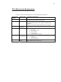
Abstract ......................................................................................................................... ii Disclaimer ....................................................................................................................iii Certification.................................................................................................................. iv Acknowledgments ......................................................................................................... v List of Figures .............................................................................................................. ix List of Tables................................................................................................................ ix Abbreviations ................................................................................................................ x Chapter 1- Introduction ................................................................................................. 1 1.1 Background.......................................................................................................... 1 1.2 Requirements ....................................................................................................... 2 1.3 Objectives ............................................................................................................ 2 1.4 Dissertation Outline ............................................................................................. 3 Chapter 2 - Background and Literature Review............................................................ 4 2.1 History of Remote Controls................................................................................. 4 2.2 Current Commercial Products ............................................................................. 4 2.3 User Interface ...................................................................................................... 4 2.4 Security ................................................................................................................ 7 2.5 Wi-Fi IEEE 802.11 Connectivity ........................................................................ 8 2.6 Infrared IR Communications and Codes ............................................................. 9 2.7 Automatic Volume Control ............................................................................... 10 2.8 Microcontrollers MCU ...................................................................................... 11 2.9 Integrated Development Environments IDE ..................................................... 12 2.10 Availability of System Components ................................................................ 12 Chapter 3 - System Design .......................................................................................... 13 3.1 System Overview............................................................................................... 13 3.2 Microcontroller MCU and IDE ......................................................................... 14 3.3 User Interface .................................................................................................... 16 3.4 MCU Web Server .............................................................................................. 21 3.5 Wi-Fi Shield ...................................................................................................... 23 3.6 Infrared Communications .................................................................................. 25 3.7 Automatic Volume Control ............................................................................... 27 3.8 Power System .................................................................................................... 31 3.9 MCU System Pin Assignments ......................................................................... 32 Chapter 4 - Implementation......................................................................................... 36 4.1 Prototype-1 ........................................................................................................ 36 vii
4.2 Prototype-2 ........................................................................................................ 37 Chapter 5 - System and Functional Testing ................................................................ 39 5.1 User Interface .................................................................................................... 39 5.2 Wi-Fi Connectivity ............................................................................................ 39 5.3 AsyncLabs Web Server ..................................................................................... 40 5.4 IRMimic2 IR Learning and Sending ................................................................. 40 5.5 SPL Microphone Hardware ............................................................................... 41 5.6 Automatic Volume Control Algorithm.............................................................. 41 5.7 Power System and Energy Usage ...................................................................... 41 Chapter 6 - Conclusion and Further Work .................................................................. 42 6.1 Conclusion ......................................................................................................... 42 6.2 Future Work....................................................................................................... 42 References ................................................................................................................... 43 APPENDICES............................................................................................................. 46 APPENDIX A - Specification ..................................................................................... 46 APPENDIX B - Requirements .................................................................................... 48 B.1) System Block Diagram .................................................................................... 49 B.2) Main System Requirements ............................................................................. 50 B.3) System Requirements and Verification Matrix ............................................... 51 APPENDIX C - Safety and Ethics .............................................................................. 54 C.1) Risk Assessment .............................................................................................. 55 C.2) Assessment of Consequential Effects .............................................................. 56 APPENDIX D - Focus Group Research ..................................................................... 57 D.1) Human Ethics Committee Application............................................................ 58 D.2) Human Ethics Committee Approval ............................................................... 70 D.3) Focus Group questions and user testing requirements .................................... 71 D.4) Results from Focus Group............................................................................... 72 D.5) Progress and Final Report ............................................................................... 73 APPENDIX E - Project Management Plan PMP ........................................................ 75 E.1) PMP Methodology ........................................................................................... 76 E.2) Resource Planning ........................................................................................... 76 E.3) Project Gantt Chart .......................................................................................... 78 E.4) Project Risks .................................................................................................... 79 APPENDIX F - Source Code ...................................................................................... 80 F.1) Code Modification Note................................................................................... 81 F.2) Main Arduino MCU ......................................................................................... 81 F.2.1) IR Testing...................................................................................................... 81 F.2.2) Main Arduino MCU ...................................................................................... 85 viii
F.3) Apple iPhone/iPad.......................................................................................... 117 F.3.1) Main Storyboard ......................................................................................... 117 F.3.2) AppDelegate.h............................................................................................. 118 F.3.3) AppDelegate.m ........................................................................................... 118 F.3.4) ViewController.h......................................................................................... 120 F.3.5) ViewController.m ....................................................................................... 121 APPENDIX G - Data Sheets ..................................................................................... 126 G.1) IRMimic2 ...................................................................................................... 127 G.2 Microphone Sound Input Module................................................................... 135 G.3) Wi-Fi CuHead Shield V2 ............................................................................. 138 G.4) Arduino compatible Uno - Freetronics Eleven.............................................. 139 G.5) Arduino compatible Uno - Freetronics EtherTen .......................................... 140 G.6) Arduino Uno .................................................................................................. 141 G.7) Arduino MEGA 2560 .................................................................................... 146 APPENDIX H - Test Results .................................................................................... 151 H.1) Apple IDE...................................................................................................... 152 H.2) MCU IDE ...................................................................................................... 152 H.3) Web Server .................................................................................................... 153 H.4) IR Controlling Devices .................................................................................. 154 H.5) Wi-Fi Shield .................................................................................................. 155 H.6) Sound Pressure Level SPL Sensor ............................................................... 159 H.7) Power Consumption ...................................................................................... 161 APPENDIX I - Design Evaluations .......................................................................... 162 I.1) Sub System Components and Tools ............................................................... 163 I.2) Project Challenges and Delays........................................................................ 163 I.3) MCU and IDE Testing .................................................................................... 163 I.4) IR Communications Testing ........................................................................... 163 I.5) DFRobot Wi-Fi Shield .................................................................................... 165 I.6) Web Server software library testing ............................................................... 166 I.7) User Interface design and testing .................................................................... 166 I.8) Apple Xcode and iPhone Application............................................................. 166 I.9) USB to RS232 Serial communications link .................................................... 166 I.10) Other MCU boards........................................................................................ 168 I.11) Basic IR hardware setup ............................................................................... 169 APPENDIX J - Self Reflection ................................................................................. 173 J.1) Self Reflection ................................................................................................ 174 ix
List of Figures
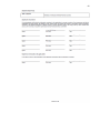
Figure 1.1 - System Overview....................................................................................... 1 Figure 2.1 - IR Remote Controls ................................................................................... 5 Figure 2.2 - A Universal Infrared Remote Control (Logitech Harmony 600) .............. 6 Figure 2.3 - Vishay IR Receiver Block Diagram, (Vishay, 2003) .............................. 10 Figure 3.1 - System Requirements Block Diagram..................................................... 13 Figure 3.2 - Arduino Freetronics Eleven board........................................................... 14 Figure 3.3 - Arduino 2560 Mega board ...................................................................... 15 Figure 3.4 - Web Page Navigation Flowchart ............................................................. 17 Figure 3.5 - Main Web Page ....................................................................................... 18 Figure 3.6 - Learn Web Page ...................................................................................... 18 Figure 3.7 - Settings Web Page ................................................................................... 19 Figure 3.8 - URL decode Error Web Page .................................................................. 19 Figure 3.9 - iPhone Application, User Interface ......................................................... 20 Figure 3.10 - LinkSprite Copperhead Wi-Fi shield V2 ............................................... 23 Figure 3.11 - iPhone Ad-Hoc connection Settings...................................................... 25 Figure 3.12 - IRMimic2, (Grieb, B 2012). .................................................................. 26 Figure 3.13 - Freetronics microphone module with gain feedback resistor ................ 28 Figure 3.14 - DC power low pass filter and changed gain resistor ............................. 29 Figure 3.15 - DC power low pass filter ....................................................................... 29 Figure 3.16 - Software controlled microphone circuit schematic ............................... 30 Figure 3.17 - Assembled software controlled microphone ......................................... 31 Figure 3.18 - 4 x 1.2 Volt NiMH, size AA Rechargeable Batteries............................ 32 Figure 3.19 - Prototype-1 pin assignment ................................................................... 33 Figure 3.20 - Prototype-2 pin assignment ................................................................... 34 Figure 3.21 - Arduino Eleven IR development pin out ............................................... 35 Figure 4.1 - Prototype-1 assembled............................................................................. 36 Figure 4.2 - Prototype-2 assembled............................................................................. 38 Figure I.1 - Measured IR wave forms using PC sound card ..................................... 165 Figure I.2 - DFRobot Arduino WIZnet Wi-Fi Shield (DFRobot) ............................. 165 Figure I.3 - Prolific USB to Serial RS232 converter................................................. 167 Figure I.4 - PCMCIA Express Serial RS232 and Parallel card................................. 167 Figure I.5 - AVR ISP Serial RS232 programmer...................................................... 168 Figure I.6 - Arduino Freetronics EtherTen LAN board with 2 G SD card ............... 169 Figure I.7 - IR circuit design and calculations .......................................................... 170 Figure I.8 - IR Tx Rx hardware ................................................................................. 171 Figure I.9 - Freetronics EtherTen IR Pin assignments .............................................. 171 Figure I.10 - Photodiode Trans-impedance amplifier ............................................... 172 List of Tables
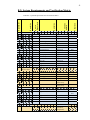
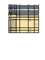
Table B.1 - Major System Requirements with Sub Requirement descriptions ........... 50 Table B.2 - System Requirements and Verification Matrix ........................................ 51 Table C.1 - Hazard, Risk Identification, Evaluation and Risk Controls ..................... 55 Table E.1 - Project Gantt Chart ................................................................................... 78 Table E.2 - Project Risks and Mitigation Actions ....................................................... 79 x
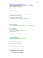
Abbreviations
The following abbreviations have been used throughout the text.
AC
AGC
AVR
CIR
DC
DVD
HTTP
I2C
IC
IDE
IEEE
IR
IrDA
LAN
MCU
NATA
NiMH
PIC
POE
PWM
RoHS
Shield
Sketch
SPI
SPL
SRVM
TCP/IP
USART
USB
WAP
WEP
Wi-Fi
WLAN
ZigBee
Alternating Current
Automatic Gain Control
Atmel MCU
Consumer Infrared
Direct Current
Digital Video Disk
Hypertext Transfer Protocol
Inter Integrated Circuit, two wire communication bus
Integrated Circuit
Integrated Development Environment
Institute of Electrical and Electronic Engineers
Infrared
Infrared Data Association
Local Area Network
Microcontroller
National Association of Testing Authorities
Nickel Metal Hydride, rechargeable battery
Microchip MCU
Power over Ethernet
Pulse Width Modulation
Restriction of Hazardous Substances Directive, European Union
Arduino stackable board
Arduino code file
Serial Peripheral Interface, programming MCU
Sound Pressure Level
Requirements and Verification Matrix
Transmission Control Protocol / Internet Protocol
Universal Synchronous Asynchronous Receiver Transmitter
Universal Serial Bus
Wi-Fi encryption
Wi-Fi encryption
Wi-Fi a trademark of Wi-Fi Alliance is used to connect to WLAN
Wireless Local Area Network
Wireless communication protocol
1
Chapter 1- Introduction
1.1 Background
Practically all consumer electronic devices in a household are controlled via infrared
remote controls. In particular media entertainment systems have a large number of
functions that are able to be controlled remotely. Consumers may have many devices
and a number of Remote Controls having various functions and layouts.
ThinkFlood the makers of RedEye suggest that ‘deep down, everyone loves
technology - or would, if it wasn’t so darn frustrating sometimes’ and ‘unreliable and
hard to use.’ (ThinkFlood, 2012a) To ease consumer’s frustration and to make
remote controls simpler, consumers are able to use a Universal Infrared Remote
Control that combines a number of remotes into one.
The use of home wireless networks, Smart Phones and Tablets enabled with Wi-Fi
has grown. Wi-Fi communications can provide a control link to a Universal Infrared
Remote Control.
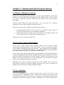
By combining these technologies, a single control interface on an iPhone or iPad then
provides a new control interface to consumer’s home entertainment systems. Or any
other devices that are capable of being Infrared Remote Controlled. See Figure 1.1 System Overview.
Figure 1.1 - System Overview
2
1.2 Requirements
The idea is to improve or extend the functionality of a consumer electronic product
called the Universal Infrared Remote Control. It is extended by adding Wi-Fi
connectivity and automatic volume control. The user interface is a Web Page in a
Web Browser or an Application on an iPhone or iPad. User commands are sent via
URL strings using standard TCP/IP HTTP protocols. See Figure 1.1 - System
Overview.
The aim is to design and build a Prototype as proof of concept.
The requirements are,
Interface
o Design, with user input from research activity
o Web Pages delivered to a Web Browser
o Apple iPhone or iPad Application
Wi-Fi connectivity
o Adhoc, point to point
o Infrastructure, WLAN Network
o Security modes
Web Server, on a low power Microcontroller
Infrared
o Receive
o Store
o Transmit
Microphone
Battery power
The objectives have been broken down into major system requirements and sub
system elements to satisfy a solution. These lower sub systems can be evaluated and
alternatives proposed for the overall system design and Prototype.
A detailed System Requirements Block Diagram is presented in Chapter 3 - System
Design. These Requirements are also linked to a System Requirements and
Verification Matrix SRVM for full system testing which is listed in Appendix B Requirements.
1.3 Objectives
The main objectives accomplished in this project include,
1. Research Infrared remote control communication, WLAN communication,
protocols and hardware.
2. Evaluate alternatives and propose an overall system design.
3
3. Design a basic Prototype for proof of concept and implement individual
building blocks that include an infrared interface, WLAN hardware, Web
interface and an iPhone or iPad application.
As time permits
4.
5.
6.
7.
8.
Investigate Remote Control interfaces and user interaction.
Propose a new interface that enhances the user experience.
Evaluate the usability of the Prototype device.
Design and implement an automatic volume gain control.
Optimise hardware power consumption.
Overall a Prototype has been built and demonstrated showing functionality covering
the objectives. A second Prototype is part of further work using a larger MCU to
extend functionality. Security has been researched but not implemented due to time
constraints.
1.4 Dissertation Outline
Chapter 1 - Introduction, to the background of the project, its requirements and
objectives.
Chapter 2 - Background and Literature Review, relates to the information required to
design the subsystems of the Prototype.
Chapter 3 - System Design, describes the subsystem components that need to be
integrated into a functioning Prototype.
Chapter 4 - Implementation, presents the working Prototype and further work on a
second Prototype.
Chapter 5 - System and Functional Testing, discusses testing of the Prototype.
Chapter 6 - Conclusion and Further Work, concludes the dissertation and summarises
the achievements of the project with a discussion on further work required to extend
functionality.
Appendix - provides further information into the overall initial investigations and
evaluations of subsystem components in producing the Prototype not documented in
the body of the Dissertation.
4
Chapter 2 - Background and Literature Review
2.1 History of Remote Controls
Remote control technology has developed over time using mechanical, wired, light,
ultrasonics, wireless and infrared transmissions links (Wang, 2001). Some devices
can also be controlled with the TCP/IP protocol that is used with computer
networking.
Infrared remote controls are cheap and simple. As a result they are a common
component used to control consumer electronic devices.
There are two main types of infrared communication protocols.
Consumer Infrared CIR for device control. For example remote control of
Televisions, DVD players, Air conditioners and lights.
Infrared Data IrDA for high speed data transfer. For example pictures and
video transfer between smart phones or digital cameras.
This project is only focusing on using CIR.
2.2 Current Commercial Products
At the start of this project, topic selection, there were no obvious similar
commercially available products on the local market. There were hardware plug-ins
for the iPhone available through online retailers. One plugged into the headphone
port at the top of the iPhone called RedEye (ThinkFlood, 2012b) and others (Breen,
2010) that plug into the large port at the bottom of the iPhone.
At the time of this project appreciation report the RedEye Wi-Fi Infrared Remote
Control (ThinkFlood, 2012b) and the Logitech Harmony Link (Logitech, 2012) have
released a full WLAN Infrared Universal Remote Control with connectivity with
iPhone, iPad and Android devices in the marketplace. The consumer electronics
industry is constantly producing new products.
Although some WLAN IR remote controls are in the market there is room for
improvement. Based on consumer feedback (Logitech, 2012) there is possibility of
adding extra functionality or making useability simpler.
2.3 User Interface
‘It is no use putting a heap of clever features into a device if the user is not
comfortable with it’ (Billingsley, 2006). Interfaces do require a lot of design work
and consumers have grown accustom to the way devices are controlled based on local
standards and previous equipment controls. Ultimately the consumer through their
5
purchasing decision determines part of the user interface design. When consumers
purchase devices they do not usually read the instruction manual before making a
purchase and so the interface needs to be intuitive in order for the user to like and
select the product (Billingsley, 2006).
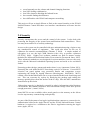
A User Interface can have many functions. Some Infrared Remote Controls are
simple and others are more complex. Looking over some Infrared Remote Controls
in Figure 2.1 - IR Remote Controls, there are common controls, layouts and themes.
Figure 2.1 - IR Remote Controls
Interesting points of interest that can be used in the design are,
power on/off is at the top, ideally red in colour
a circular up/down left/right with a centre select button is common
larger linked button for volume up/down, mute
larger linked button for channel up/down
media - play/stop/pause, forward, backwards, record
a numeric keypad
four coloured macro function buttons
the background case colour to button colour or contrast for ease of viewing
text size, colour and contrast
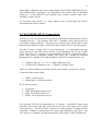
These common controls are found on Universal Infrared Remote Controls, see Figure
2.2. This controller is mid range, there are more complex touch screen ones and
much simpler ones.
6
Figure 2.2 - A Universal Infrared Remote Control (Logitech Harmony 600)
One major disturbance is to look at and read a button label before an action is
selected. Poor lighting on passive remote interfaces are a problem whereas an iPhone
or iPad is backlit. One problem with touch screen devices is they lack tactile
response (Breen, 2010). The user is unable to feel around the controls while keeping
their eyes on the viewing screen to select an action.
With the popularity of the internet, smart phones and tablets now ingrained into the
lives of many technology conscious consumers, an interface using these devices can
now be an application (Craft & McElveen, 2010) or a Web Page. A Web Page can
use HTML Cascading Style Sheet CSS to format and make the Web Page interface
more appealing (Lemay, 2003). To produce Web Pages the MCU needs to include a
Web Server that can serve HTML using the HTTP protocol.
So why do some controls have different shapes, sizes, surfaces and colours? How
does this affect the user and what do they think about different interfaces? And what
would be the best features to put into an interface? To gain more specific information
about Infrared Remote Controls and how they are used a Focus Group Discussion
Research Activity has been undertaken, see results in the Appendix D.
Key outcomes from the discussion group on interfaces indicated that users,
like simple interfaces that they can see and read at night in low light levels
require prompting to navigate more complex navigation
like all-in-one universal remotes but don’t like programming them
7
most frequently use the volume and channel changing functions
don’t like dealing with batteries
don’t like obstacles blocking the Infrared beam
have trouble finding their Remotes
have difficulties with WLAN and computer networking
This project will use an Apple iPhone or iPad as the control interface to the WLAN
Infrared Remote Control and these user interface considerations will enter into the
design.
2.4 Security
Security encompasses the access and the control of the system. It also deals with
protecting the integrity of the system from modifications and counterfeiters. There
are many areas and levels of security technology.
Access to the system can be controlled with user authentication using a login to stop
any unauthorised control of equipment. This could also allow for the use of
ciphertext for network communications (Thomas, T 2004). A simple method of
encryption is to use the logic XOR function with a key to produce ciphertext
(ELE3305, 2009). Higher level software methods use built in mature security
modules like Microsoft DotNet that bind to Event controls (Freeman & Jones, 2003).
These advanced methods are not designed for microcontrollers, however they may
work with the Microsoft embedded Operating System and needs to be researched
further.
Protecting product design, patents and market share is very important (Codan, 2012).
Protecting the code inside the MCU from being copied is of concern. Correct MCU
selection can guard against copy protection attacks and competitors reverse
engineering the design by ripping firmware (Skorobogatov, 2000/2004). MCUs
contain a fuse bit that when burnt out or set prevents the flashed code from being read
out. This can overcome by copiers by dissolving the package and reading the
memory optically direct from the surface of the IC chip. Here the MCU manufacture
Atmel backs up this claim.
‘Robust data security is absolutely essential in today's information-critical business
environments. But standard memories and conventional storage often don't provide
enough protection.’ (Atmel, 2012a).
Atmel MCUs are now available with a metal guard over the memory at the silicon
level to stop memory contents being read optically.
As part of the Deployment of an Apple Application that connects to a remote device,
authentication between the Apple iDevice and the WLAN Infrared Remote Control
hardware is required as a condition to the iDevice Application entering the Apple
store (Apple, 2012a).
8
Atmel offers a hardware chip set for authentication, the AT88SA10HS/102S devices.
The AT88SA102S is designed to be embedded in the product with an embedded
265bit key. It uses SHA-256 and responds with a unique response when sent a
challenge. (Atmel, 2012b)
As encryption and security is a large complex area of knowledge this will be
implemented last if time permits.
2.5 Wi-Fi IEEE 802.11 Connectivity
A Wireless Local Area Network WLAN allows connection and data transfer between
computing devices. The different IEEE 802.11 standards ensure different devices
can connect without problems. This project is concerned only with the 802.11 b/g/n
modes that the iPhone 4 (Apple, 2012b) and iPad 2 (Apple, 2012c) can both support.
The MCU needs to support 802.11 b/g/n connectivity. It is anticipated that only
small amounts of data will need to be sent, so the throughput speed is not critical.
There will need to be a balance of data throughput and power consumption with a
power sleep mode to maximise battery life. There are a number of different
manufactures for Arduino Wi-Fi Shield modules with Wi-Fi connectivity they are,
DFRobot, 802.11b 11, 5.5, 2, 1 Mbps (DFRobot, 2012)
CuHead Wi-Fi Shield 802.11b 1, 2Mbit/s (CuteDigi, 2012)
There is a software library (AsyncLabs, 2012a) and examples (AsyncLabs, 2012b).
Connection Mode can be either,
AdHoc - point to point
Infrastructure - through a network
Wi-Fi Security modes,
No security
WEP, Wired Equivalent Privacy
WPA, Wi-Fi Protected Access
WPA2, Wi-Fi Protected Access 2
For simplicity UDP will be controlled via a C Library. Serial RS232 with a port
allocation will not be used. This will allow for the use of the higher level TCP/IP
connection layer. The Wi-Fi MCU connection is different than a standard TCP/IP
connection. Packets are smaller due to the processing capabilities of the MCU. The
code will be in C language and functions depend on the choice of Wi-Fi Shield type.
9
2.6 Infrared IR Communications and Codes
Codes
For the WLAN IR Remote Control to control multiple electronic consumer devices it
needs to use CIR Standards. The big problem is there is no real common standard for
CIR. This is because the CIR control of devices has evolved over time from early
days and it was not until interference between devices became a problem that
something was done. Big name manufactures have implemented their own
Standards. Adding to the complexity, each manufacture has varying code types that
have evolved over time.
There is a large variety of IR modulation signals associated with commands. They
are well documented by Bergmans (2012) and Shirriff (2009). This adds some
decoding and algorithm complexity to the project. Common IR codes include
(Vishay, 2003),
Phillips RC5, RC6
NEC
SONY
Toshiba Micom Format
Sharp
RCMM
R-2000
RECS-80
Raw waveform
One way to overcome the decoding of the modulation signals is to store the captured
signal as a raw waveform and then retransmit it when required. One drawback to this
is more memory is needed in the MCU (Shirriff, 2009).
A deicated IC that can store up to 57 IR codes/waveforms and play them back is
IRMimic2 PIC IC by Tauntek (Grieb, B 2012) and identified by AVRFreaks as a
reliable solution (AVRFreaks, 2012).
Carrier Frequency
There are a number of different carrier frequencies in use. If the carrier frequency is
not matched between the transmitter and receiver the link will be degraded or just not
work. Carrier frequencies are mostly set by crystals. Sometimes crystals of the
correct frequency were hard to get and manufactures used what they could get. This
resulted in slightly different carrier frequencies being used. A common carrier
frequency range is about 38 kHz. (Vishay, 2003),
10
Infrared Transmission
An Infrared IR Light Emitting Diode LED look like a common LED but their output
wavelength is invisible to humans. Some have a clear or blue moulded casing with a
lens. The spectral wavelength required is 940 nm known as Far Infrared. IR LEDs
have expected bandwidth of 50 nm and beam angle 30 degrees with power levels of
100mW (Jaycar, 2010), datasheets (Everlight, 2004), (Taitron, 2007). For hardware
testing purposes the IR spectral emission can be seen by a camera (Shirriff, 2009).
Infrared Reception
An Infrared IR Photodiode detects and receives Infrared energy levels. The device
has some capacitance and its output is a current. To overcome this and to look at
faster signals a trans-impedance or current to voltage converter is needed (Neamen,
2007).
Infrared receiving detectors can be interfered with or receive IR energy from other
sources like sun light, fluorescent lamps and heating points. To overcome false
readings of signals the bursts or pulses of IR are modulated by the transmitter. The
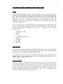
modulation carrier frequency is commonly 38 kHz. An Integrated Circuit IC with a
combined converter amplifier, filter and demodulator is available like the Vishay
TSOP41xx, (Vishay, 2003). A block diagram of this IR receiver IC is in Figure 2.3 Vishay IR Receiver Block Diagram.
Figure 2.3 - Vishay IR Receiver Block Diagram, (Vishay, 2003)
2.7 Automatic Volume Control
Automatic Gain Control AGC is often implemented in electronics to normalise a
signal level. In radios this may be the volume.
11
By the inclusion of a microphone that can pick up the sound pressure level in the
room the MCU software can then send volume down and up commands based on a
hysteresis type algorithm. It is intended that this optimisation of the algorithm will
require some trial and error testing.
A microphone hardware module by Freetronics is available and could be adapted for
the Prototype (Freetronics, 2012). By using an 8-channel analogue multiplexer /
demultiplexer 4051 IC the gain can be digitally controlled through software (delabs,
2005).
2.8 Microcontrollers MCU
A kit called ‘WIB Web server In a Box’ supplied by Silicon Chip (Grassi 2009). This
kit has been built and tested by the Dissertation Author. It contains a PIC MCU
running a TCP/IP wired LAN interface and Web Server. Performance is not the same
as a PC however it is a low power solution and a proof of concept that a MCU can be
used for this project.
Microcontroller selection will consider a number of important factors,
Hardware specification
o Number of Inputs/Outputs and type, Analogue, Digital, PWM
o Internal timers
o Register sizes
o UARTs
o Memory size and speed
o Operations optimization
o Availability
o Environmental like vibration and temperature ranges
o Low power requirements, sleep modes
Cost of both hardware and firmware development
Reliability, and life span
Programming IDE and firmware programmer
Operating system / boot loader
Security of embedded firmware
Power requirements
Environmental
product support
There is a lot of 8/16/32 bit Microcontroller manufactures. A number of development
boards are available from some of the manufactures along with examples that are
generally optimised for specific applications. The 8 bit MCUs for consideration are
Atmel AVR (Atmel, 2012) and Microchip PIC (Microchip, 2012) based on cost,
availability and the support tools required. Further analysis of other MCU brands and
type has not been performed.
12
2.9 Integrated Development Environments IDE
Both Atmel AVR Studio 5 (Atmel, 2012c) and Microchip MPLAB v8.66 (Microchip,
2012) are professional MCU IDEs which are free to use. Optional optimising C
compilers and programming modules for in-system debugging are available at extra
cost.
The Arduino MCU IDE version 1.0 is more simplified with only the most basic
features suited mainly for hobbyists. It supports the AVR MCU and supports a large
number of plug in modules from many different manufactures using a common
header pin out (Arduino, 2012). There is also an Arduino based board with a PIC
MCU available. Arduino boards mostly contain the AVR MCU and the code can also
be written and compiled using Atmel AVR Studio (EngBlaze, 2012).
The Apple iDevice IDE Xcode can be downloaded and used on an iMac. A
developer fee of $99 per year is required and the developer must be registered.
iDevices are linked to the developers registration and software can only be deployed
to the registered iDevices (Apple, 2012a).
2.10 Availability of System Components
The supply and availability of components required to build a Prototype at low cost
can be restrictive. Integrated Circuit and MCU Chip manufactures take minimum
orders by the 1000’s. The Atmel and Microchip PIC MCU manufactures produce
development kits that support their parts. Other single purchase of components may
be available through retailers at added cost.
Companies and part availability can come and go in months. A large company
‘Microchip was ranked No.4 after Atmel, which climbed to No. 3 from No. 5’ and
Steve Sanghi, Microchip CEO ‘recently bought Roving Networks, a Calif-based
company providing Bluetooth and Wi-Fi modules and solutions’ as of 7th May 2012
(Yoshida J, 1012) This may have affected the supply of some types of Arduino
Wi-Fi Shields.
Parts also include software systems and libraries. Software changes and updates are
not always backward compatible to previous components. The Arduino and MCU
open source community along with forums is rich with applied knowledge that solves
these problems. (Arduino, 2012) (AVRFreaks, 2012)
This information suggests that parts for system components need to be ordered in
advance with some thought as to their continued availability and delivery times.
13
Chapter 3 - System Design
3.1 System Overview
The design is broken into modules. Modules that pass testing form the Prototype.
The production of an embedded system MCU Design and methodology is discussed
by Leung (2012)
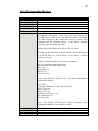
The overall design for the Prototype is best managed by defining each requirement
that is easily referenced. These requirements are modelled into a system block
diagram for a system overview. Each subsection has been designated a requirement
number with sub-requirements. This is mostly fine grained with a lot of detail, see
Figure 3.1- System Requirements Block Diagram. Or for a larger view see Appendix
B. This has been done for full system testing and is tracked using a System
Requirements and Verification Matrix SRVM also listed in Appendix B.
VER 5 - 2012.10.22.11:22
IR WLAN Remote Control Requirements Block Diagram
R1 Input
Key
R2 Interface
Hardware
Software
R1 User commands
R2 Apple iPhone / iPad
R3-1.1A
R3-1
.4
R3
-1
.1
B
R2-5 USB
.2
-1
R3
R5-2
Software
development
R5-2.1.1 R5-2.1.2
USB
LAN
R5-2.1 Apple
R5-1.2 Test
Equipment
R5-2.2.2
WiFi
R5-2.2.1
USB
R5-2.2 Microsoft
R5-2.2.3 Arduino
R5-2.2.1.1
R3-2 Internet
R4 Controller
R6 Controlled
Devices
R4-4 Wi-Fi Rx Tx
.3
-1
R4-4.2
jumper
R3
R3-1.5
R3-1 WLAN
R4-4.1 Wi-Fi firmware
R4-4.3 WiFi settings
R6-1
TV
R4-1.2 Serial link to WiFi shield
R4-1 microprocessor 1
Arduino (ATMEL AVR)
R4-1.1
USB to
UART
R4-1.4
RAM
R5-1.1 Tools
R2-3 R2-4
HTTP Wi-Fi
Rx/Tx
R4-3 Battery
R5-1
Hardware
development
R2-2.1
Web page
Existing System
.1
R5 Development
Environment
R2-2 web browser
Link
R3 Network
R2-1 Apple App
R4-1.4 Arduino OS
R4-1.5 Web Server
R4-1.6 IR cmd
Microphone
SPL
R4-1.3 MCU interface
R5-2.1.3 Xcode
R5-2.2.4 Terminal
R4-2 microprocessor 2
IRMimic (Microchip PIC)
R5-2.1.4 iTunes
R5-2.2.5 WizNet
R4-2.1 Infrared Transceiver
firmware
Figure 3.1 - System Requirements Block Diagram
R4-2.3 R4-2.2
Digital Digital
Out
In
R1-1.1 Select TV
R1-1.2 Select DVD
R1-1.3 Select Air Con
R1-1.4 Select Light
R1-2.1 TV volume up
R1-2.2 TV volume down
R1-2.3 TV volume mute
R1-2.3 TV channel up
R1-2.3 TV channel down
R1-3.1 DVD play
R1-3.2 DVD stop
R1-4.1 A/C on
R1-4.2 A/C off
R1-5.1 Light on
R1-5.2 Light off
R5
-2 .
1.1
1
2
3
4
5
6
7
8
9
10
11
12
13
14
15
R4-5
IR Rx
R4-6
IR Tx
R6-2
DVD
R6-3
A/C
R6-4
Light
14
The Prototype hardware design includes, Wi-Fi, Infrared receive store and transmit,
microphone, a control MCU with Web Server, and a battery.
The final stages of the software design includes, IR code learning and sending, Wi-Fi
connected Web Server with HTML Web Pages, an iPhone or iPad Application,
factory software reset, user settings and a software controlled microphone gain. A
discussion group and user testing was performed to provide feedback on the design.
Security needs to be implemented.
Overall this project uses a number of relatively mature technologies that are
integrated into the Prototype solution.
3.2 Microcontroller MCU and IDE
The Microcontroller MCU selected for Prototype-1 is the Arduino Atmel AVR328p.
It is an 8 bit 16 MHz MCU with 2 k SRAM, 32 k Program memory and just enough
I/O to test concept. The Arduino board contains a power regulator and an onboard
USB to serial programmer. The Arduino platform has been designed for rapid
prototyping. Arduino has set a standard for its header pin out which has been used
with pluggable boards called Shields to add functionality to the project. See Figure
3.2 - Arduino Freetronics Eleven board.
Figure 3.2 - Arduino Freetronics Eleven board
15
After initial testing it has been determined that the Web Server needs more SRAM for
its runtime variables. Without making too many changes to the initial design a
second MCU board is still being worked on for Prototype-2 to extend the base
functionality. The Arduino 2560 Mega has 8 k SRAM and a further 256 k Program
memory with more I/O. It is the next higher equipped Arduino development board,
see Figure 3.3 - Arduino 2560 Mega board.
Figure 3.3 - Arduino 2560 Mega board
Both the Arduino hardware MCU boards are supported by the Arduino Integrated
Development Environment IDE for writing of the software code and downloading the
compiled files into the MCU. The code is written in C and uses Arduino variables
and functions. The higher level C programming language is a better choice to code
higher levels of functionality and software complexity for the project.
The Arduino platform supports many hardware shields with corresponding libraries
extending purpose fit functionality. The Arduino IDE works on both the Microsoft
Windows and Apple Operating Systems. The project has used the Microsoft
Windows Arduino IDE version. Migration of MCU code from Arduino IDE to AVR
Studio IDE is possible but has not been done.
The Arduino platform advantages include,
local MCU board, parts and shield availability
various Wi-Fi modules available
code examples
IDE includes USB on board programming
low cost
16
3.3 User Interface
From the research of common controls and their layout a user interface design can be
created. Feedback from the user discussion group including control usage patterns
suggests a simple design is a good starting point. Based on these considerations a
simple basic test interface to control a portable DVD player will contain,
volume up
volume down
play / stop
forward
back
on/off, red
other, blue
The Web Page interface will be driven by the MCU Web Server that can post simple
HTML text strings and get HTTP URL requests for commands. Some nicer simple
web page design can be managed by using HTML, CSS and picture icons (Lemay,
2003). A full icon driven interface can be used instead of text with an advantage of
being user language independent.
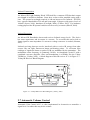
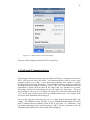
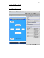
The structure and navigation of the Web Page interface is in Figure 3.4 Web Page
Navigation Flowchart, flowed by Figures 3.5, 3.6, 3.7 and 3.8 for the Web Pages. To
get the Prototype working correctly the menu navigation had to be scaled down and
the web pages made very simple, see MCU code in Appendix F. It seems the
AVR328p MCU 2 k SRAM struggled to stay stable. Removing debug serial output
prints helped and all string constants for the HTML text were placed into program
memory. The Arduino IDE does not have any memory management or in system
debugging tools. It is only through trial and error that this simple menu of Web Pages
has produced a satisfactory result. Further adjustments to the Web Server may also
help.
17
Figure 3.4 - Web Page Navigation Flowchart
18
Figure 3.5 - Main Web Page
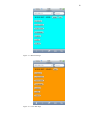
Figure 3.6 - Learn Web Page
19
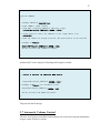
Figure 3.7 - Settings Web Page
Figure 3.8 - URL decode Error Web Page
20
Applications for the Apple iPhone / iPad are written in Apple Objective C syntax
(DeVoe, 2011) using the Apple Xcode IDE. The setup, development and application
installation process is well described by iPhone Game Development (Craft, &
McElveen, 2010) with further information on the Apple Developer web site. The
registration process requires acceptance of the licence agreement with Apple. To use
the IDE a yearly fee is required and the developed software can only run on apple
devices registered to the developer’s key. The key has to be backed up on a USB
drive. There are different levels of developer contract with Apple based on software
functions and services used. In order to have the application submitted in the Apple
App store the hardware needs to be submitted to Apple and kept by Apple at cost to
the developer. Any change to the hardware or software means the device has to be
resubmitted to Apple.
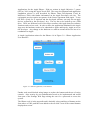
A simple Application written for the iPhone 4 is in Figure 3.9 - iPhone Application
User Interface.
Figure 3.9 - iPhone Application, User Interface
Further work would include using images to replace the buttons and the use of swipe
controls. Also security by user authentication needs to be implemented and would
form part of the Settings Web Page asking the user for a password to access the
system.
The iPhone code is in the appendix and is basically a drag and drop of buttons on the
form where a URL path has been added to the on-click event of the control buttons
displayed on screen.
21
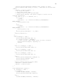
3.4 MCU Web Server
The Web Server is central to the design as it provides the interface. It is an integrated
component of Wi-Fi hardware. The Wi-Fi AsyncLabs Web Server Library is used. It
has a different Library and has different functionality than the tested Freetronics
EtherTen LAN Web Server.
The Library files are downloaded from GitHub repository. For the WiShield,
AsyncLabs has to abide by the terms in the license for the driver code ‘g2100’ for the
Wi-Fi module, which is provided by ZeroG Wireless Inc.
The files are then installed by performing a copy and paste of the WiShield folder
into the Arduino IDE libraries folder.
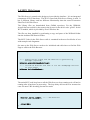
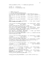
The MCU Code for the Web Server calls is examined in the next few blocks of text
with example code fragments.
On start up the Web Server needs to be initialised and told where to find the Web
Page to send to the Web Browser.
void setup()
{
.
.
.
//--- Enable Serial output and ask WiServer to generate log
messages (optional)
WiServer.enableVerboseMode(true);
.
.
.
}
//--- Initialize WiServer and have it use the sendMyPage function
to serve pages
WiServer.init(sendMyPage);
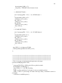
The main MCU code loop has to call the Web Server to keep starting as it will not be
running after it has done its processing. The loop delay also needs to be increased to
cater for more URL decoding, but not too much.
void loop()
{
}
WiServer.server_task();
.
.
.
delay(100);
//--- Run WiServer
22
The Web page HTML strings are printed from program memory and processing of
received URL commands after a number of packets has finished being sent. See the
next example code fragment.
boolean sendMyPage(char* URL)
{
.
.
// check if Web Page has been sent, as it is a number of packets
if((0==(int)uip_conn->appstate.ackedCount)
&&
(0==(int)uip_conn>appstate.sentCount)) // is ready
.
.
.
//---VOLUME UP command --else if (strcmp(URL, "/S1") == 0) //SEND button 1
{
//Serial.println("URL=/S1"); //VOL UP
IR_CSEL(1); //select memory location number 1
IR_SEND(); //send IR pulse train
}
.
.
.
//finish URL processing calls, now send web pages
// Home web page
if (strcmp(URL, "/") == 0) // just IP address of home page
{
// write page content from flash memory
webpHOME();
WiServer.print_P(flash memory HTML text string);
return true;
}
.
.
.
}
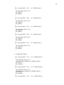
The ASYNCLABS apps-conf.h Library needs to be edited to define the variable
APP_WISERVER
.
.
.
//
//
.
.
.
Filename:
Description:
apps-conf.h
Web application configuration file
#define APP_WISERVER
.
.
.
This presents the core of the Web Server design.
23
3.5 Wi-Fi Shield
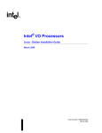
After initial evaluation testing of the DFRobot Wi-Fi Shield, the Copperhead Version
2 Wi-Fi Shield was selected. See Figure 3.10 - LinkSprite Copperhead Wi-Fi shield
V2.
The Copperhead Version 2 Wi-Fi Shield meets the design requirements of,
Wi-Fi mode 802.11b 2.4 GHz
Connectivity modes of Adhoc and Infrastructure
Security options, none, WEP, WAP, WAP2
Data communication using the TCP/IP layer
Software Library
Other specifications include (CuteDigi, 2012),
rechargeable battery circuit
16 Mbit serial flash, good for storing Web Pages
1Mbps and 2Mbps throughput speeds
Low power usage
Sleep mode: 250μA, Transmit: 230mA, Receive: 85mA
Microchip Wi-Fi module
Figure 3.10 - LinkSprite Copperhead Wi-Fi shield V2
MCU code software setup settings that contain IP addresses, connection modes and
security options.
24
.
.
.
#define WIRELESS_MODE_INFRA
#define WIRELESS_MODE_ADHOC
1
2
// Wireless configuration parameters ---------------------------------------unsigned char local_ip[] = {192,168,1,2};
// IP address of WiShield
unsigned char gateway_ip[] = {192,168,1,1};
// router or gateway IP address
unsigned char subnet_mask[] = {255,255,255,0}; // subnet mask for the local network
const prog_char ssid[] PROGMEM = {"IRMCU"};
// max 32 bytes
unsigned char security_type = 0;
// 0 - open; 1 - WEP; 2 - WPA; 3 - WPA2
// WPA/WPA2 passphrase
const prog_char security_passphrase[] PROGMEM = {"12345678"};
//max64 characters
// WEP 128-bit keys
// sample HEX keys
prog_uchar wep_keys[] PROGMEM = { 0x01, 0x02, 0x03, 0x04, 0x05,
0x09, 0x0a, 0x0b, 0x0c, 0x0d, // Key 0
0x00, 0x00, 0x00, 0x00, 0x00, 0x00,
0x00, 0x00, 0x00, 0x00,
// Key 1
0x00, 0x00, 0x00, 0x00, 0x00, 0x00,
0x00, 0x00, 0x00, 0x00,
// Key 2
0x00, 0x00, 0x00, 0x00, 0x00, 0x00,
0x00, 0x00, 0x00, 0x00 // Key 3
};
// setup the wireless mode
// infrastructure - connect to AP
// adhoc - connect to another Wi-Fi device
unsigned char wireless_mode = 2; //WIRELESS_MODE_ADHOC;
0x06, 0x07, 0x08,
0x00, 0x00, 0x00,
0x00, 0x00, 0x00,
0x00, 0x00, 0x00,
unsigned char ssid_len;
unsigned char security_passphrase_len;
// End of wireless configuration parameters -----------------------.
.
.
The Settings for the iPhone to make the Ad-Hoc mode connection is given in Figure
3.11 - iPhone Ad-Hoc connection settings.
25
Figure 3.11 - iPhone Ad-Hoc connection Settings
This part of the design provides the Wi-Fi connectivity.
3.6 Infrared Communications
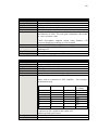
Initial design evaluation testing using an Arduino IR Library, Vishay receiver and an
IR Tx LED was not 100% successful. Two identical back to back IR receive store
transmit systems were setup. It was found that problems were mainly in reliably
decoding and transmitting IR signals. Even though the library displayed consistent
decoding results, the output waveforms varied. The same system that decoded and
transmitted a signal could not then do the same back, see Appendix Test results.
Receiving, storing and transmitting the raw IR signal was successful. The next
design problem was to store even longer IR signals as used with the Microsoft Xbox
360. At this stage in the project time was extended and ran out. This further work
was left to time availability on Prototype-2.
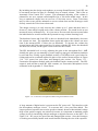
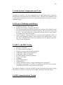
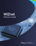
To overcome the time restrictions the use of a single purpose designed MCU was
sought. The IRMimic2 from TaunTek is a pre programmed Microchip PIC MCU
with 57 channels that are trainable (Grieb, B 2012), see Figure 3.12 - IRMimic2. One
big design advantage for the main Prototype-1 MCU was the separation of the IR
functions and the Web Server load, aiding code debugging.
26
Figure 3.12 - IRMimic2, (Grieb, B 2012).
The MCU mode is set by setting pin 23 MDE low with a 470 ohm resistor on power
start up.
The IRMimic2 MCU control lines are,
CSEL 0-5, 0-56 command memory locations
LRNRQ, learn request
LRNERR, learn error
SNDRQ, send request
RDY, ready
Data Sheet and circuit diagram is in Appendix G.
Arduino MCU code example for learning an IR signal
.
.
.
// select a channel in IRMimic2 MCU memory
// set channel pins
if (2==CSELset)
{
Serial.println("2==CSELset");
digitalWrite(pin_IRMimic2_CSEL_0,LOW);
digitalWrite(pin_IRMimic2_CSEL_1,HIGH);
digitalWrite(pin_IRMimic2_CSEL_2,LOW);
}
.
27
.
.
void IR_LEARN()
{
.
// Manage IRMimic2_LearnErrors
.
// make LRNRQ = HIGH (learn)
// then RDY = LOW and IRMimic2 LED will light
digitalWrite(pin_IRMimic2_LRNRQ, HIGH);
// using Timer 0 //wait for IRMimic to be ready about 2 ms
delay(3);
// Hold IR remote to Vishay receiver and push button to be learned
// Manage a Timeout
.
.
.
}
digitalWrite(pin_IRMimic2_LRNRQ, LOW);
Serial.println("IR_LEARN finished");
Arduino MCU code example for Sending an IR signal is similar.
.
.
.
// select a channel in IRMimic2 MCU memory
.
.
.
digitalWrite(pin_IRMimic2_SNDRQ, HIGH);
// Manage a Timeout for hardware errors
digitalWrite(pin_IRMimic2_SNDRQ, LOW);
Serial.println("IR_SEND finished");
}
This presents the IR design.
3.7 Automatic Volume Control
The user focus group research has indicated that one of the most frequent adjustments
using a remote control is volume.
28
By including into the design a microphone, an average Sound Pressure Level SPL can
be measured and used as part of a feedback loop to control volume. This is like an
Automatic Gain Control AGC system. This automated adjusting of the volume is
planned for use on a separate sound amplifier for a Television media centre. In this
way no animated volume bars are seen on a Television screen. Some Televisions
may be able to turn off the animated on screen volume bars and the Prototype could
directly control the Television volume unit.
The design concept is to only increase the volume up to 3 times and then lower it
down to 3 times while keeping track of the volume position. The sound levels are not
measured in any calibrated way. It is just met to increase and decrease around what
the individual user would consider their personal average volume listening level.
The hardware listens and if the SPL is above a threshold code immediately decreases
the volume one time. The algorithm listens again and reduces the volume one more
time if the measured SPL is above the set threshold. To increase the volume the
system listens and if the room sound level is quieter with the SPL below the threshold
for about six seconds, an IR signal is sent to increase the volume.
The SPL threshold level is set by adjusting the gain on the microphone R4, 1 MΩ.
Initially the gain was set manually by some rough op-amp gain calculations and then
by trial and error. Finally a gain feedback resistor of 220 kΩ proved a good value for
testing and can be seen hand soldered in place of the surface mount resistor in Figure
3.14 - DC power low pass filter and changed gain resistor. See Figure 3.13 Freetronics microphone module with gain feedback surface mount resistor. The SPL
output is used and has a small RC time constant, see Freetronics Microphone circuit
schematic in the Appendix G - Data Sheets.
Figure 3.13 - Freetronics microphone module with gain feedback resistor
A large amount of digital noise is present on the DC power rail. This interferes with
the microphones analogue circuit. To overcome this, a low pass filter added. The
largest practical capacitor was used to get the resistance down so that minimal voltage
drop on the positive supply was achieved, because it is important to maintain output
voltage levels for interfacing with the analogue to digital converter on the MCU. See
Figure 3.14 - DC power low pass filter and changed gain resistor. Once the Prototype
is working successfully further work would include reducing the size of the capacitor.
29
Figure 3.14 - DC power low pass filter and changed gain resistor
The filter uses a low Q ferrite bead inductor, 220 ohm resistor, 470 μF, 25 V
capacitor. This produces a measured 0.28 Volt drop on the supply rail for the
Microphone circuit. The RC time constant is 103 ms and the ferrite bead should
reduce high frequency components as it shouldn’t be saturated with current. This
circuit could be refined with further analysis and measurements as future works.
Overall the DC power filter works well, see Figure 3.15 - DC power low pass filter.
Figure 3.15 - DC power low pass filter
30
Due to a longer overall response time taken to process a volume send command. The
command is sent twice in the Arduino MCU code and works well.
There is a need for the user to be able to adjust this gain. This can be done through
the user interface by using software to control the Microphone gain and set a SPL
threshold. The hardware implementation is performed with a 4051 Multiplexer /
Demultiplexer IC being a digitally controlled analogue switch. See Figure 3.16 Software controlled microphone circuit schematic.
Vin
Vout
1 MΩ
feedback
47 kΩ
4051
3
+ 5 Volt
16
A
11
B
10
C
9
6
7
8
150 kΩ
13
14
15
12
1
5
2
4
47 kΩ
47 kΩ
47 kΩ
47 kΩ
47 kΩ
47 kΩ
Figure 3.16 - Software controlled microphone circuit schematic
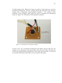
The assembled software controlled microphone is shown in Figure 3.17. It has been
tested and is working correctly ready for inclusion into Prototype-2. With the
inclusion of the 4051 Multiplexer / Demultiplexer IC a larger 2200 μF capacitor is
being trialled in the DC power filter.
31
Figure 3.17 - Assembled software controlled microphone
3.8 Power System
The Arduino standard has a 2.1 mm power socket that accepts a DC input of +7 to
+12 volts which can be powered from a mains AC power plug pack. The board can
also be powered from the USB +5 volt serial cable. USB power is used during
software development.
The inputs are regulated by an onboard power converter supplying the common
power header with,
+5.0 V, 200 mA
+3.3 V, 50 mA
unregulated input voltage
The Atmel AVR 328p MCU output pin rating is 5 V at 40 mA.
Power usage is important. The Arduino main MCU has a low power sleep mode.
Parts of the circuit should be switched off when not in use. The Wi-Fi Shield is power
hungry however it supports a power saving sleep mode. Power saving actions also
includes managing unused pins and circuit functions (STMicroelectronics, 2012).
Power saving features have not been enabled, it is further work for Prototype-2.
32
‘The IR sensor module requires a small amount of operating current whenever it is
powered. For good battery life, it is necessary to power down the IR sensor module
except when learning. The IR Mimic2 chip handles this automatically.’ (Grieb, 2012).
CuHead Wi-Fi shield power consumption specifications
o
o
o
Sleep mode: 250 μA
Transmit: 230 mA
Receive: 85 mA
The systems total average current will be measured in the results section and will give
an indication of battery life.
A 6 volt 4 x 1.5 Volt size AA Alkaline battery connected directly to the 2.1 mm
power socket will under power the MCU. This battery will need to be connected
through a silicon power diode to the +5.0 Volt power header pin.
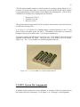
To keep the voltage down Prototype-1 will use 4 x 1.2 Volt NiMH cells with the total
supplied voltage about 4.8 Volts. This will drop as the battery loses its charge.
Figure 3.18 - 4 x 1.2 Volt NiMH, size AA Rechargeable Batteries
Figure 3.18 - 4 x 1.2 Volt NiMH, size AA Rechargeable Batteries
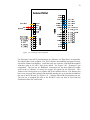
3.9 MCU System Pin Assignments
A number of sub systems have been combined. A summary of the pin connections on
the Arduino Eleven for Prototype-1 is in Figure 3.19 - Prototype-1 pin assignment.
33
Figure 3.19 - Prototype-1 pin assignment
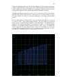
For Prototype-2 the MCU pin allocations are different, see Data Sheets in Appendix.
Not all pins have been assigned. The Wi-Fi shield is not handling interrupts correctly
and needs further investigation. Until then only the software controlled Microphone
with three pins A, B, and C have been added. See Figure 3.20 - Prototype-2 pin
assignment. The pin out for IRMimic2 connection has not been added as further
work needs to continue on storing the longer IR signals for the Xbox360. This
further work is being done on a separate MCU the Arduino Eleven. The Header pins
have been removed and replaced with stackable header pins so it can then be added to
the top of the PCB stack, see Figure 3.21 - Arduino Eleven IR development pin out.
The pin out is arranged like this so the IR MCU code can also be used with the
Freetronics EtherTen LAN board.
34
Arduino MEGA 2560
Pin Out
AREF
GND
LED 13
12
Reset MCU
PWM 11
3V3
PWM 10
5V
PWM 9
GND
VIN
WiFi Status LED
8
DIGITAL
GND
POWER
Battery
+
-
RESET
7
PWM 6
Reset Settings
0
PWM 5
4
ANALOGUE
1
2
3
4
PWM 3
2
TX 0 1
5
RX 0 0
6
COMMUNICATION
7
8
9
40
38
36
34
32
30
41
39
37
35
33
31
22
42
43
24
44
45
23
46
47
26
48
49
25
50
51
28
GND
52
SPL A
GND
SPL B
Figure 3.20 - Prototype-2 pin assignment
SPL C
WiFi MOSI
15
SDA 21
DIGITAL
WiFi SS
14
SDA 20
53
13
TX 1 18
RX 1 19
27
12
TX 2 16
RX 2 17
29
WiFi SCK
11
WiFi MISO
ANALOGUE
10
TX 3 14
RX 3 15
WiFi INT 0
35
Figure 3.21 - Arduino Eleven IR development pin out
36
Chapter 4 - Implementation
4.1 Prototype-1
The sub system elements of the design are implemented in the first functional
Prototype-1. The Hardware and Software components are listed below.
Hardware boards and Shields have been stacked together and consist of,
Infrared IRmimic2 MCU with Learn / Store / Send
Factory Settings Reset Button
Wi-Fi connectivity, CuHead WiShield V2
Main MCU with Web Server
Fixed gain Microphone with DC power filter
Battery Pack
See Figure 4.1 - Prototype-1 assembled
Figure 4.1 - Prototype-1 assembled
37
MCU Software components consist of,
AsyncLabs Web Server
simple Web Pages
Factory Wi-Fi configuration settings
simple Factory Reset of IP address only
simple display of Settings
limit of seven IR channels stored and learnt, max is 57
all seven IR channels can be Sent
Automatic volume enabled
serial print out for debugging and program status
Note: Software features are limited but functional due to the 2k SRAM limit of the
AVR328p MCU affecting the Web Server performance. Further design work has
continued on the Arduino Mega2560 MCU board that has increased resources.
User interface is functional with both the Web Browser WebPages and the iPhone
Application. From user input in the Focus Group discussion research a simple
interface was delivered to enhance the user experience.
Web Pages are simple and there layout is exactly as described in Chapter 3 System
Design
Send
Learn
Settings
Error
iPhone Application is also displayed in Chapter 3 System Design
one page simple buttons
one button to open Web Browser for command Learning and Settings
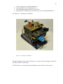
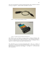
4.2 Prototype-2
Further work continues on with Prototype-2, it is not fully operational. It uses the
Arduino Mega 2560 with 8k SRAM and more digital I/O. This allows for extending
the functionality of the user interface and software controlled features
Hardware boards and Shields stack consist of,
Infrared Transmit, Receive, status LED, command button
Arduino AVR MCU Infrared with Learn / Store / Send
Factory Settings Reset Button
38
Wi-Fi connectivity, CuHead WiShield V2
Arduino MEGA 2560 with Web Server
Fixed gain Microphone with DC power filter
Battery Pack to be added, may use battery circuit on CuHead WiShield V2
See Figure 4.2 - Prototype-2 assembled
Figure 4.2 - Prototype-2 assembled
The MCU Software is the same as Prototype-1 except for pin out changes to allow for
the different MCU connections.
The Web Server is not fully operational and that is the final state of the project.
39
Chapter 5 - System and Functional Testing
This section gives details of the testing and evaluation of system components and
functions of Prototype-1. Further test and evaluation results are in the Appendix.
Testing of the full system has been marked on the SRVM in Appendix B Requirements. Appendix H - Test Results, includes pre-testing and evaluation testing
leading to Prototype-1 Testing.
A Serial Terminal program was also used to check and validate correct MCU
program execution.
Prorotype-1 was demonstrated during the Focus Group discussion research activity
and to the project Supervisor successfully.
5.1 User Interface
Web Browser and Web Pages - The designed Web Pages all worked and were able
to be viewed on a networked computer, iPad and iPhone through a Web Browser. By
keeping the design to only send simple HTML text strings there were no problems in
rendering the Web Pages and performance was good both through Adhoc and
Infrastructure Wi-Fi connection modes. The Web Page reads the screen resolution
and correctly sets the pixel width of iPhone so the Web Page text is large enough to
read on large and small screens. Each button was pressed and worked. Entering
other URL commands that were not in the URL decode code produced the URL Error
Web Page as expected and allowed the user to navigate back to the Send Home page.
Sometimes the Web Server was a little delayed in processing URL commands, but
once a command was processed the following commands were quick.
iPhone Application - Touching the Application Icon successfully launched the
program. Each button on the simple interface was tapped and worked. To access the
other areas of the system a button in the lower left corner opened the Web Browser
and allowed the system to be programmed through the Web Pages. The Application
gave a more seamless integration look and feel to the system as with the Web
Browser the user could see the processing activity.
5.2 Wi-Fi Connectivity
The CuHead WiShield V2 was successful and maintained a reliable TCP/IP Wi-Fi
connection. The Security modes tested were None and WAP2. The connection was
nearly instant using no security, however it took about 30 seconds to establish a
connection using WAP2. Both Adhoc and Infrastructure connection modes both
work ok as the IP addressing and settings could all be changed. The module did not
get hot. The red on board LED correctly indicated when it was working.
40
5.3 AsyncLabs Web Server
Keeping the Web Pages and Menu simple as well as limiting the amount of URL
string decoding kept the Web Server stable. After setting up the AsyncLabs Library
and using the Arduino IDE 0023 the Web Server was successfully implemented. If
any more system variables were used the Web Server was unstable. Even though the
MCU code compiled and downloaded correctly, no warnings were given. Much
functionality was rolled back to make the Web Server stable.
To process URL commands the code needed to test when the server response had
finished. Supporting documentation indicating how to do this did not work and when
the Library was opened the code had a comment noting that it was unfinished and not
coded. This may have been a regression bug in the Library as other online sources
indicated that it does work. The Library was the only version available on GitHub.
This needs further investigation.
It is critical that the Web Server be sorted out for further functionality to be extended
as the whole system relies on it.
5.4 IRMimic2 IR Learning and Sending
Testing of the IRMimic2 chip was successful on all the home media devices and air
conditioner except for the XBox360. This Xbox360 results is supported by Shirriff
(2009). The length of IR codes for an Xbox360 is longer than the codes for the tested
Sony Amplifier and TV. The IRMimic2 chip cannot store the longer Xbox360 IR
codes and this part of the project will need further work.
The IRMimic2 chip easily learnt IR signals. The LED indicator helped the user know
when the IR code had been learnt. There were a few minor attempts to improve the
learning of the volume commands as they were repeat codes. The user had to press
the sending volume code quickly and not hold the button down, that’s all. This
learning setup information would have to be added to the user manual. Overall the
IRMimic2 chip worked very well.
On power up some times the IRMimic2 chip would start up in learning mode and
overwrite a memory location. The possible cause is the SRAM limit on the Arduino,
because when functionality was reduced by reducing program variables the problem
seemed to disappear. Further investigation of the start up states of the Arduino pins is
required along with using some professional MCU IDE tools.
During testing the IR beam from the LED was not able to be viewed by the camera in
the iPhone. After some more research a different camera was used and the Tx LED
was viewed as working by an electronic digital SONY camera.
41
5.5 SPL Microphone Hardware
The added DC low pass filter stops the digital noise and the analogue circuit works
well. Tapping the microphone lit the green LED indicating the SPL threshold was
being reached. A louder volume of sound was adjusted coming from a Television
and then a music player. The SPL threshold was triggered and gain was about right.
5.6 Automatic Volume Control Algorithm
Prototype-1 was left running for about two hours listening to room SPL from
commercial Television showing advertising and also movie content. The volume up
command was sent allowing the volume to increase to the SPL threshold. Then the
volume down command was sent for sound levels above the SPL threshold. When
people entered the room to make conversation the volume automatically lowered as
people tried to talk above the sound of the Television. The volume lowered
automatically and conversations were at a more pleasant volume. Once the person
left the room the volume had to be manually increased. Overall the algorithm works
well.
5.7 Power System and Energy Usage
Power saving measures have not been implemented. The IRMimic2 has a built in
power saving mode enabled. Measured current was about 135 mA on average with
currents exceeding 160 mA when the Wi-Fi was communicating.
The Battery voltage is different based on cell chemistry either Alkaline 6 Volts or
NiMHi 5 Volts. Voltage to the positive power rail was slightly increased above 5
Volts but the positive supply rail did not increase. This may be due to the regulator
having some Zenner type protection also the 3.3 Volt rail was ok.
With the voltage and current measurements rough battery life calculations of
2450 mAh / 135 mA = about 18 hours. With the inclusion of sleep modes for both
the MCU and the Wi-Fi Shield this time could be greatly extended.
42
Chapter 6 - Conclusion and Further Work
6.1 Conclusion
Prototype-1 achieves the objectives with limited functionality in each area due to
Web Sever processing times and MCU 2K SRAM limit.
Achievement of Objectives,
User interface both Web browser and iPhone Application
User research undertaken
Wi-Fi connectivity, connection modes, security modes
Web Server
IR code learning and sending
Automatic volume control
Battery powered
Successful Testing demonstration
The outcomes of the objectives for the project have successfully proved concept and
further works continue to extend functionality.
User testing and demonstration of Prototype-1 has showed that consumer IR
electronic devices can be controlled by a web page or an application running on an
iPhone or iPad.
6.2 Future Work
It is critical that the Web Server be sorted out for further functionality to be extended
as the whole system relies on it.
To extend functionality the Arduino Mega 2560 is being used. It has 8kSRAM and
more digital I/O. This MCU upgrade should be enough to extend all functionality.
Development of the MCU software using the Arduino IDE version 023/1.1 is
increasingly difficult for this large project. Further MCU software development
needs to be in the more professional IDE, AVR Studio 6. Where memory usage can
be tracked and debugging features can be utilised with the use of an Atmel hardware
programmer and debugger.
Once the hardware functionality is acceptable, the Apple application can also be
enhanced to include icons and swipe controls with more advanced menus.
43
References
Apple, 2012a, Developer, Apple, Cupertino, viewed 21st May 2012,
<https://developer.apple.com/>
Apple, 2012b, iPhone 4 Tech Specs, Apple, Cupertino, viewed 14th Oct 2012,
< http://www.apple.com/iphone/iphone-4/specs.html/>
Apple, 2012c, iPad 2 Technical Specifications, Apple, Cupertino, viewed 14th Oct
2012, < http://www.apple.com/ipad/ipad-2/specs.html/>
Arduino, 2012, Arduino home web site, Arduino, Cocos (Keeling) Islands, viewed 19
May 2012, < http://www.arduino.cc/>
AsyncLabs, 2012a, AsyncLabs WiShield Library, AsyncLabs, viewed 2nd May 2012,
<http://asynclabs.com/wiki/index.php?title=WiShield_library>
AsyncLabs, 2012, AsyncLabs Wiki, AsyncLabs, viewed 14nd Oct 2012,
<http://asynclabs.com/wiki/index.php?title=AsyncLabsWiki>
Atmel, 2012a, Home > Products > More Products - Hardware Security Solutions Safeguarding Secrets at the Silicon Level, Atmel, San Jose, viewed 4th Sep 2012,
<http://www.atmel.com/products/other/default.aspx >
Atmel, 2012b, Home > CryptoAuthentication™ Product Uses, Atmel, San Jose,
viewed 4th Sep 2012, <http://www.atmel.com/Images/doc8663.pdf>
Atmel, 2012c, Home Page, Atmel, San Jose, viewed 21st May 2012,
<http://www.atmel.com/>
AVRFreaks, 2012, Home Page, viewed 21st May 2012, <http://www.avrfreaks.net/>
Bergmans, S 2012, SB-Projects: IR Control , Oisterwijk, Netherlands, updated 22
May 2011, viewed 10th May 2012,
<http://www.sbprojects.com/projects/ircontrol/index.php>
Billingsley, J 2006, Essentials of Mechatronics, Ch 14 The Human element, Wiley,
USA
Breen, C 2010, ‘iPhone IR remotes compared: Five remotes compared’, MacWorld,
Jul, 2010, viewed 22nd May 2012,
<http://www.macworld.com/article/1151573/iphone_ir_remotes.html>
Codan, 2012, ‘Codan fights Chinese counterfeits’, Electronics News, Apr., p 6.
Craft, C & McElveen, J 2010, iPhone Game Development, Wiley, Indianapolis
CuteDigi, 2012, LinkSprite Cuhead Wi-Fi Shield V2.0 for Arduino, cutedigi,
Lognmont, viewed 4th May 2012,
<http://www.cutedigi.com/wireless/Wi-Fi/linksprite-cuhead-Wi-Fi-shield-v2-0-forarduino.html>
44
Delabs, 2005, Schematics of delabs: Digital gain control of Opamp, viewed 5th Jul
2012, <http://schematics.dapj.com/2005/01/digital-gain-control-of-opamp.html>
DFRobot, 2012, Wi-Fi Shield V2.1 For Arduino (802.11 b/g/n), Pudong, China,
viewed 19 May 2012,
<http://www.dfrobot.com/index.php?route=product/product&product_id=548>
ELE3305 Computer systems and communications protocols, Faculty of Engineering
and Surveying, 2009, University of Southern Queensland
EngBlaze, 2012, Tutorial: Using AVR Studio 5 with Arduino projects, EngBlaze,
viewed 09th May 2012, <http://www.engblaze.com/tutorial-using-avr-studio-5-witharduino-projects/>
Engineers Australia, 2012, Code of Ethics, Engineers Australia, viewed 18th May
2012,
<http://www.engineersaustralia.org.au/sites/default/files/shado/About
Us/Overview/Governance/CodeOfEthics2000.pdf>
Everlight, 2004, Technical Data Sheet 5 mm Infrared LED, Everlight Electronics,
<www.everlight.com>
Freeman, A & Jones, A 2003, Programming .NET Security, O’Reilly, Sebastopol
Freetronics, 2012, Home Page, Freetronics, Croydon Hills, viewed 21st May 2012,
<http://www.freetronics.com/>
Grassi, M 2009a, ‘WIB Web server In a Box: part 1’, Silicon Chip, Nov., pp. 24-36.
Grassi, M 2009b, ‘WIB Web server In a Box: part 2’, Silicon Chip, Dec., pp. 82-95.
Grassi, M 2010a, ‘WIB Web server In a Box: part 3’, Silicon Chip, Jan., pp. 85-87.
Grassi, M 2010b, ‘WIB Web server In a Box: part 4’, Silicon Chip, Apr., pp. 20-25.
Grieb, B 2012, IRMimic2 Trainable IR Remote Control Transmitter with Macros,
Tauntek, San Diego, viewed 21st May 2012
<http://www.tauntek.com/irmimic2-learning-ir-remote-control-transmitter.htm>
Jaycar, 2010, Jaycar Electronics Catalogue 2010, p 73, Rydalmere
Lemay, L 2003, Sams Teach Yourself Web Publishing with HTML and XHTML in 21
Days, 4th edn Sams, Indianapolis
Leung, L 2012, ‘Crossing the development chasm’, Electronics News, Apr., pp 14-17.
Logitech, 2012, Logitech Harmony Link, Logitech Newark USA, viewed 13 May
2012, <http://www.logitech.com/en-us/1225/8439>
Microchip, 2012, Home Page, Chandler, Arizona, viewed 21st May 2012,
<http://www.microchip.com/>
45
Neamen, D 2007, Microelectronics Circuit Analysis and Design, 3rd edn, Mc Graw
Hill, New York
Shirriff, K 2009, Ken Shirriff's blog, viewed 18 March 2012,
<http://www.arcfn.com/search?q=IR>
Skorobogatov, S 2000, Copy Protection in Modern Microcontrollers, University of
Cambridge:
Computer
Laboratory,
viewed
11
May
2012,
<http://www.cl.cam.ac.uk/~sps32/mcu_lock.html>
Skorobogatov, S 2004, Semi-invasive attacks .A new approach to hardware security
analysis, University of Cambridge: Computer Laboratory, viewed 11 May 2012,
<http://www.cl.cam.ac.uk/techreports/UCAM-CL-TR-630.pdf>
STMicroelectronics, 2012, ‘Limiting MCU power consumption’, Electronics News,
Apr., pp 20-21.
Taitron, 2007, Taitron Components, 5 mm Infrared LED, Taitron, Valencia
<http://taitroncomponents.com>
ThinkFlood, 2012a, About ThinkFlood, ThinkFlood Needham USA, viewed 19 May
2012, <http://thinkflood.com/company/about/>
ThinkFlood, 2012b, RedEye Products, ThinkFlood Needham USA, viewed 19 May
2012, <http://thinkflood.com/products/>
Thomas, T 2004, Network Security first-step, Cisco, Indianapolis
USQ, 2012, Human ethics clearance, University of Southern Queensland, viewed
18th May 2012, <http://www.usq.edu.au/research/ethics/human/clearance>
Vishay, 2003, IR Receiver Module for Remote Control Systems, viewed 24 Mar 2012,
<http://www.vishay.com/ir-receiver-modules/list/product-82135/>
Wang C, 2001, Infrared Remote Room Light Switch, Ch 2.1, University of
Queensland, Brisbane, viewed 14 Oct 2012,
<http://innovexpo.itee.uq.edu.au/2001/projects/s369729/thesis.pdf>
WHO, 2012, Media centre, Electromagnetic fields and public health, viewed 19th Oct
2012, <http://www.who.int/mediacentre/factsheets/fs304/en/index.html>
WIZnet, 2012, Home Page, Korea, viewed 6th March 2012,
<http://www.wiznet.co.kr/>
Yoshida J, 1012, Talk from the hip at Microchip, EETimes News & Analysis, viewed
13 May 2012, <http://www.eetimes.com/electronics-news/4372400/Talk-from-thehip-at-Microchip?cid=NL_EETimesDaily>
Zeldovich, K 2012, Zelscope Oscilloscope and spectrum analyser, viewed 21st May
2012, <http://www.zelscope.com/>
46
APPENDICES
APPENDIX A - Specification
47
University of Southern Queensland
FACULTY OF ENGINEERING AND SURVEYING
ENG4111/ENG4112 Research Project
PROJECT SPECIFICATION
FOR:
John Palmer
TOPIC:
WIRELESS LAN BASED INFRARED REMOTE CONTROL
SUPERVISOR:
Dr. Alexander A. Kist
ENROLMENT:
ENG4111 – S1, EXT, 2012
ENG4112 – S2, EXT, 2012
PROJECT AIM:
Practically all consumer electronic devices in a household are
controlled via infrared remote controls. The aim of this project is
to design and build a device with which can act as a stationary
remote control. The device itself is controlled via a Web interface
or iPad/iPhone application.
PROGRAMME:
Issue C, 4th April 2012
9. Research Infrared remote control communication, WLAN communication,
protocols and hardware.
10. Evaluate alternatives and propose an overall system design.
11. Design a basic prototype (proof of concept) and implement individual
building blocks (infrared interface, WLAN hardware, Web interface and an
iPad/iPhone application).
As time permits
12. Investigate remote control interfaces and user interaction.
13. Propose a new interface that enhances the user experience.
14. Evaluate the usability of the prototype device.
15. Design and implement an automatic volume gain control.
16. Optimise hardware power consumption.
AGREED:
Date:
______________________
/
/ 2012
John Palmer (student)
______________________
/
/ 2012
Dr. Alexander A. Kist (supervisor)
48
APPENDIX B - Requirements
49
B.1) System Block Diagram
50
B.2) Main System Requirements
Table B.1 - Major System Requirements with Sub Requirement descriptions
Requirement
Number
1
Requirement
Description and activities
Input
2
Interface
3
WLAN
Network
Controller
A set action required by the user.
Investigate remote control user interaction.
Investigate remote control interfaces.
Design an interface for the user to input a command to the
controller.
Propose a new interface that enhances the user experience.
Investigate WLAN protocols and hardware.
4
5
Development
Environment
6
Controlled
Device
The embedded hardware and software system design includes,
1. Main MCU
2. IR communications
3. Power system
4. WiFi hardware
5. Volume automatic control.
All the tools required to build the system prototype.
1. Hardware
2. Apple platform
3. Microsoft platform
Any Infrared Remote Controllable components of the consumers
home media system or other device.
51
B.3) System Requirements and Verification Matrix
R2
R3
R4
Compliance
Verification
Method
User commands
Description
Description
R1
Derived
Requirement
Requirement
Table B.2 - System Requirements and Verification Matrix
R1-1.1
Select TV
Inspection
N/A
R1-1.2
Select DVD
Inspection
N/A
R1-1.3
Select Air Con
Inspection
N/A
R1-1.4
Select Light
Inspection
N/A
R1-2.1
TV volume up
Inspection
Pass
R1-2.2
TV volume down
Inspection
Pass
R1-2.3
TV volume mute
Inspection
Tested ok
R1-2.3
TV channel up
Inspection
Pass
R1-2.3
TV channel down
Inspection
Pass
R1-3.1
DVD play
Inspection
Pass
R1-3.2
DVD stop
Inspection
Pass
R1-4.1
A/C on
Inspection
Tested ok
R1-4.2
A/C off
Inspection
Tested ok
R1-5.1
Light on
Inspection
N/A
R1-5.2
Light off
Inspection
N/A
R2-1
Apple App
Testing
Pass
R2-2
Web browser
Inspection
Pass
R2-2.1
Web page
Testing
Pass
R2-3
HTTP
Testing
Pass
R2-4
WiFi Rx / Tx
Pass
R2-5
USB
Inspection connectivity
Inspection connectivity
R3-1
WLAN
Inspection
Pass
R3-1.1
Apple iPhone / iPad
Inspection
R3-1.2
Apple iMac
Inspection
iPhone
Pass
Pass
R3-1.3
Microsoft W7 PC
Inspection
Pass
R3-1.4
Arduino
Inspection
Pass
R3-1.5
Internet
Inspection
Pass
R3-2
Internet
Inspection
Pass
Apple
iPhone / iPad
Pass
Network
Controller
testing percussion,
temperature,
52
light, EMI
R4-1
microprocessor
1
Arduino (ATMEL AVR)
Inspection
Pass
R4-1.1
USB to UART
Pass
R4-1.2
Serial link to WiFi shield
R4-1.3
MCU interface
R4-1.4
Memory
Testing connectivity
Testing connectivity
Testing connectivity
Tested
R4-1.4
Arduino OS
Tested
Pass
R4-1.5
Web Server
Tested
Pass
R4-2
microprocessor 2
IRMimic (Microchip
PIC)
R4-2.1 Infrared
Transceiver firmware
Tested
Pass
Tested
Pass
R4-2.2
Digital In
Tested
Pass
R4-2.3
Digital Out
Tested
Pass
R4-3
Battery
Testing
Pass
R4-4
WiFi Rx Tx
Pass
R4-4.1
WiFi firmware
R4-4.2
jumper
Testing, self
check
Inspection,
Check firmware
version
Inspection
R4-4.3
WiFi settings
Inspection,
Check all
parameters are
saved
Pass
R4-5
IR Rx
Testing, check bit
stream
Pass
R4-6
IR Tx
Testing, by video
camera
Pass
R5-1
Hardware development
Tested
Pass
R5-1.1
Tools
Tested
Pass
R5-1.2
Test Equipment
Tested
Pass
R5-2
Software development
Tested
Pass
R5-2.1
Apple
Tested
Pass
R5-2.1.1
USB
Tested
Pass
R52.1.1.1
R5-2.1.2
USB cable
Tested
Pass
LAN
Tested
Pass
R5-2.1.3
Xcode
Tested
Pass
R4-2.1
R5
Pass
Pass
Pass
Pass
Pass
Development
Environment
53
R6
R5-2.1.4
iTunes
Tested
Pass
R5-2.2
Microsoft
Tested
Pass
R5-2.2.1
USB
Tested
Pass
R52.2.1.1
Tested
Pass
USB cable
R5-2.2.2
WiFi
Tested
Pass
R5-2.2.3
Arduino
Tested
Pass
R5-2.2.4
Terminal
Tested
Pass
R5-2.2.5
WizNet
Tested
Pass
R6-1
TV
Pass
R6-2
DVD
Testing - user
command
response
Testing - user
command
response
Controlled
Devices
Pass on
DVD
played
Failed on
Xbox 360
DVD
player
R6-3
A/C
R6-4
Light
Testing - user
command
response
Testing - user
command
response
Pass
N/A
54
APPENDIX C - Safety and Ethics
55
C.1) Risk Assessment
There are a number of Hazards identified with the construction of this project.
Electrical Power Mains via DC adaptor and batteries and their charging.
Battery explosion / fire.
Heat, Soldering.
RF energy from the WiFi Module.
Electrostatic discharge.
Chemical, solder fumes, paint, plastics.
Eating or chocking of packaging materials and small parts by children.
Asphyxiation so plastic packaging bags needs holes.
Soft tissue damage from cutting and drilling.
Repetitive strain from typing and using hand tools.
These have been evaluated with controls in the table below.
Table C.1 - Hazard, Risk Identification, Evaluation and Risk Controls
Hazard
Electrical
Risk
likelihood
Very rarely
Risk
Exposure
Very slight
Risk
Consequence
Possible death
Heat
Frequently
Slight
Skin and eye
injury
RF energy
Frequently
Low
Skin cell damage
Electrostatic
discharge
Significant
Occasionally
Chemical
Solder and
cleaners
Drill
Slight
Occasionally
Shock and
Component
damage
Skin and eye
injury
Slight
Occasionally
Skin and eye
injury
Cutting wire
Significant
Regularly
Chocking
Very slight
Very rarely
Skin and eye
injury
Possible death or
brain damage
Asphyxiation
Very slight
Very rarely
Possible death or
brain damage
Risk
Control
Isolation
Gloves
Isolation
Gloves
Protective eyewear
Isolation
Gloves
Anti-static mat
& wrist strap
Good ventilation
Gloves
Protective eyewear
Isolation,
use guards
Gloves
Protective eyewear
Gloves
Protective eyewear
Reduce and
eliminate small
parts, bags.
Give Warnings
All bags need
holes and Warning
labels
56
C.2) Assessment of Consequential Effects
Consequential effects
Some possible effects could be,
Lowering level of physical exercise increasing the risk of weight gain and
associated health problems.
Repetitive muscular strain from overuse.
The changing of TV viewing content and volume by station owners.
Security issues of unauthorised access to control equipment.
WLAN RF exposure limits
‘Considering the very low exposure levels and research results collected to date,
there is no convincing scientific evidence that the weak RF signals from base
stations and wireless networks cause adverse health effects’ (WHO, 2012).
Ethical responsibility
To perform any user surveys or observations requires approval from the USQ Ethics
Committee (USQ, 2012). This ensures approval by participates, their safety and a
level of separation such that no links to any persons involved in users surveys can be
made.
Using Engineers Australia code of ethics (Engineers Australia, 2012) and being
responsible and of benefit to the community and produce a safe design, which leads
to considerations for this project like,
Make people’s lives and the environment safe.
Assist people with mobility problems.
Consider safety issues like, Risk of fire from battery recharging.
Eliminate Chemical exposure, plastics, Lead free, and look for RoHS
compliance.
Take care in the final product shape. Remove sharp edges or any figure
jamming resulting in soft tissue damage
Manage small part safety s like case screws and batteries
Reduce any eye strain when viewing the controls.
Manage end of life disposal of electronics on the environment, so choose
recyclable components.
57
APPENDIX D - Focus Group Research
58
D.1) Human Ethics Committee Application
59
60
61
62
63
64
65
66
67
68
69
70
D.2) Human Ethics Committee Approval
71
D.3) Focus Group questions and user testing requirements
University of Southern Queensland
Faculty of Engineering and Surveying
Wireless LAN Based Infrared Remote Control
Ethics Approval No: H12REA143
Researcher: John M Palmer
Date :
29 / 08 / 2012
1) Discussion group
General discussion of the topics,
The number of remote controls users have and what devices they control.
The use of all-in-one remotes, their setting up and purchase costs.
Any problems or frustration in using remote controls.
The commands buttons or actions that are used the most.
Any experience in the use of Wireless LAN or computer networking.
Questions / other points of interest
2) User testing
User testing of the device design by end users. This is to include the use of an iPhone
and an iPad with the following activities,
Un-boxing of device.
Setup of the device connectivity.
Teaching the device to learn commands.
General use of the programmed device and user experience.
Questions and feedback
OUTCOME
Action points to refine and improve the designs user interface and functionality.
72
D.4) Results from Focus Group
Wireless LAN based Infrared remote Control
Ethics Approval No: H12REA143
Date: 29-08-2012
Response to Questions
Users generally have a few Remote Controls and are usually controlling a TV,
amplifier and content.
Most users have heard of all-in-one universal remote controls. Some liked
them others hated them and gave them away. The problem was that they were
too hard to program and have too many buttons or functions.
Users expect the cost of Remote Controls to be less than $100 to $40 AUS
based on features.
Users find media Infrared Remote Controls have too many buttons, generally
causing confusion when trying to quickly find a function like ‘Stop’. Users
however still want to access all the features of their consumer devices.
Some buttons cannot be seen at night or are hard to read especially in low
light.
The most frequently used commands are volume and channel functions with
generally 2-3 other special functions.
Users don’t like dealing with batteries.
Users don’t like things getting in the way blocking the IR beam for example,
people and cabinet glass doors
Users have trouble finding their remote controls.
Users have a mixed experience in WLAN computer networking. They have
common connection problems like the connection is saying it is connected but
the connection is not working. They want a single button fix and a
connected/not connected indicator.
User testing results
Users said the Prototype was a bit big and users requested a smaller size. It
was explained that a final version would be a similar size to current Remote
Controls and they were happy with that.
The setup and connection through the iPhone was demonstrated and users
were happy with the simple WLAN connection.
Users liked the simple and easy Infrared code learning function for single
commands.
Users liked the simple iPhone interface and found the web page text a bit
small. It was explained to the users that the web page should be like the
iPhone app but is a limitation of the Microcontroller MCU and would be
enhanced in a final design.
73
D.5) Progress and Final Report
74
75
APPENDIX E - Project Management Plan PMP
76
E.1) PMP Methodology
Project planning assists in the full completion of the project by managing time,
resources, and activities.
Early Resource planning helps manage time and mitigate risks. Parts have been
ordered early as availability and delivery times are a risk.
Hardware is to be validated and ordered 30 days in advance.
Software testing and licensing is to be paid and activated early.
Timeline management is planned via a project Gantt chart indicating approximately
when and how much time is required for Tasks. Time for testing, fault analysis,
fixing hardware and MCU code, and documenting could take up a large amount of
the timeline.
Project risks are identified and risk mitigation and actions are noted.
E.2) Resource Planning
(R5-1) Hardware
CRO/DSO or PC audio scope, Zelscope on Microsoft Windows XP
multimeter
soldering iron
hand tools
Arduino prototyping boards and Shields
components
4 x AA battery holder and batteries
solder exhaust extraction
lamp
magnifying glass
(R5-2) Apple iMac platform
iDevice user interface,
Objective C syntax text
iPhone game development text
Apple iMac with Xcode IDE and certificate keys
iPhone, iPad
USB software transfer cable
77
(R5-3) Microsoft Windows XP/W7 Platform
Arduino MCU board,
MS Windows PC XP, W7
AVR studio 5, 5.1, 6 needs Microsoft Windows and Microsoft Visual Studio
Arduino Microsoft Windows IDE 1.0
Serial terminal, Putty
USB to mini USB software transfer cable
Arduino WiFi Shield - setup and Serial programming link requires,
Arduino board running sample code file Blink containing serial UART code.
USB to mini USB cable
Serial link header pins 0 RX and 1 TX availability
jumper pins on WiFi Shield
WiFi Shield configuration program running on Microsoft Windows and
manual
78
E.3) Project Gantt Chart
Table E.1 - Project Gantt Chart
79
E.4) Project Risks
Project risks in not completing or delaying project.
Id
1
Table E.2 - Project Risks and Mitigation Actions
Risk
Impact
Likelihood Mitigation Actions
(Low
Description
/Medium
/High)
Personal Lost
Delay
Low
Schedule slack
Time, illness
Action
Contact examiner if
bad
Failure of
Hardware
Software
Skills shortfall
Delay
Medium
Backup data
Have hardware spare
Reassess alternatives
Delay
Medium
Seek help from
supervisor.
4
Parts
availability
problems
Delay
High
Research well.
Seek help from
supervisor.
Order early. Schedule
hardware design early.
5
Spend more
time on task
than allocated.
Delay,
Reduced time
budget
Medium
Reassess Task and
look for possible
alternatives.
Adjust other task
times.
2
3
Reassess alternatives
80
APPENDIX F - Source Code
81
F.1) Code Modification Note
Code has been updated with the Authors initials //JMP, such that existing example
code is used that comes with the IDE’s or Libraries and its content is property of the
original author or IDE.
To assist in debugging in the Arduino MCU code, later changes for each line of code
has been marked with a Version number to help locate bugs.
In the Apple code listing some changes have been highlighted.
F.2) Main Arduino MCU
F.2.1) IR Testing
/*
* IRrecord: record and play back IR signals as a minimal
* An IR detector/demodulator must be connected to the input
RECV_PIN.
* An IR LED must be connected to the output PWM pin 3.
* A button must be connected to the input BUTTON_PIN; this is the
* send button.
* A visible LED can be connected to STATUS_PIN to provide status.
*
* The logic is:
* If the button is pressed, send the IR code.
* If an IR code is received, record it.
*
* Version 0.11 September, 2009
* Copyright 2009 Ken Shirriff
* http://arcfn.com
*/
// Code modified by [email protected] with date time stamp
and comments.
//
// I Have had to use IDE023 to get libraries to work and code to
compile.
// 2012.04.15.16:25.SU -- testing Rx and Tx for W7HP media player
remote.
// The system is not working and displaye RC6: 800F046E for 'play
button'
// I also tested a SONY amplifier, SONY TV, Xbox360 but did not
work.
//
// can see IR LED Tx in video camera ok.
// check circuit details, IR LED current about 94mA (5V_vcc1.2V_IRled-0.7V_TRvce)/33ohm
//
// Using a photodiode and transimpedance op-amp with 1 V p-p output
// and Zelscope on MS XP this code is not decoding the Rx stream
corectly into HEX.
82
//
// TRY, look at A/D sampling time in
<IRRemote.h>,<IRRemoteInt.h>,<IRRemote.cpp>
// TRY, changing pulse length and tolerance constants.
// TRY, adjusting the Tx IR LED carrier frequency.
//
// JMP 2012.04.15.19:45.SUN, force raw "Tx codeType = -1;" works,
good result
// JMP 2012.04.15.20:04.SUN, when set to 36 kHz, pulses later in the
train fail.
// JMP 2012.04.15.20:04.SUN, worked at 40 kHz, exact match to
waveform
// JMP 2012.04.15.20:24.SUN, sucessful start / stop MS Win7 media
player
// JMP 2012.04.16.07:33.MON, migrate code from IDE023 to IDE1.0
// move IDE1.0 folders to root path to shorted length of compile
error messages.
// change #include <WProgram.h> to #include <Arduino.h> in
IRRemoteInt.h,
// now compiles OK in IDE1.0
#include <IRremote.h>
int RECV_PIN = 5;
int BUTTON_PIN = 6;
int STATUS_PIN = 7;
//JMP 2012.04.15.16:33.SUN , updated
//JMP 2012.04.15.16:33.SUN , updated
//JMP 2012.04.15.16:34.SUN , updated
IRrecv irrecv(RECV_PIN);
IRsend irsend;
decode_results results;
void setup()
{
Serial.begin(9600);
Serial.println("Started IRmod");//JMP 2012.04.15.16:25.SUN ,added
irrecv.enableIRIn(); // Start the receiver
pinMode(BUTTON_PIN, INPUT);
pinMode(STATUS_PIN, OUTPUT);
}
// Storage for the recorded code
int codeType = -1; // The type of code
unsigned long codeValue; // The code value if not raw
unsigned int rawCodes[RAWBUF]; // The durations if raw
int codeLen; // The length of the code
int toggle = 0; // The RC5/6 toggle state
// Stores the code for later playback
// Most of this code is just logging
void storeCode(decode_results *results) {
codeType = results->decode_type;
//******************************************************************
*
codeType = -1; //JMP 2012.04.15.19:45.SUN ,added debug FORCE RAW
MODE
//******************************************************************
*
int count = results->rawlen;
if (codeType == UNKNOWN) {
83
//Serial.println("Received unknown code, saving as raw");
Serial.println("JMP saving as raw"); //JMP 2012.04.15.18:39.SUN
,added
codeLen = results->rawlen - 1;
// To store raw codes:
// Drop first value (gap)
// Convert from ticks to microseconds
// Tweak marks shorter, and spaces longer to cancel out IR
receiver distortion
for (int i = 1; i <= codeLen; i++) {
if (i % 2) {
// Mark
rawCodes[i - 1] = results->rawbuf[i]*USECPERTICK MARK_EXCESS;
Serial.print(" m");
}
else {
// Space
rawCodes[i - 1] = results->rawbuf[i]*USECPERTICK +
MARK_EXCESS;
Serial.print(" s");
}
Serial.print(rawCodes[i - 1], DEC);
}
Serial.println("");
}
else {
if (codeType == NEC) {
Serial.print("Received NEC: ");
if (results->value == REPEAT) {
// Don't record a NEC repeat value as that's useless.
Serial.println("repeat; ignoring.");
return;
}
}
else if (codeType == SONY) {
Serial.print("Received SONY: ");
}
else if (codeType == RC5) {
Serial.print("Received RC5: ");
}
else if (codeType == RC6) {
Serial.print("Received RC6: ");
}
else {
Serial.print("Unexpected codeType ");
Serial.print(codeType, DEC);
Serial.println("");
}
Serial.println(results->value, HEX);
codeValue = results->value;
codeLen = results->bits;
}
}
void sendCode(int repeat) {
if (codeType == NEC) {
if (repeat) {
irsend.sendNEC(REPEAT, codeLen);
Serial.println("Sent NEC repeat");
}
else {
irsend.sendNEC(codeValue, codeLen);
84
Serial.print("Sent NEC ");
Serial.println(codeValue, HEX);
}
}
else if (codeType == SONY) {
irsend.sendSony(codeValue, codeLen);
Serial.print("Sent Sony ");
Serial.println(codeValue, HEX);
}
else if (codeType == RC5 || codeType == RC6) {
if (!repeat) {
// Flip the toggle bit for a new button press
toggle = 1 - toggle;
}
// Put the toggle bit into the code to send
codeValue = codeValue & ~(1 << (codeLen - 1));
codeValue = codeValue | (toggle << (codeLen - 1));
if (codeType == RC5) {
Serial.print("Sent RC5 ");
Serial.println(codeValue, HEX);
irsend.sendRC5(codeValue, codeLen);
}
else {
irsend.sendRC6(codeValue, codeLen);
Serial.print("Sent RC6 ");
Serial.println(codeValue, HEX);
}
}
else if (codeType == UNKNOWN /* i.e. raw */) {
// Assume 38 KHz
//irsend.sendRaw(rawCodes, codeLen, 38);
irsend.sendRaw(rawCodes, codeLen, 40); //JMP
2012.04.15.20:04.SUN, modify
// JMP 2012.04.15.20:04.SUN, when set to 36 kHz, pulses later in
the train fail.
// JMP 2012.04.15.20:04.SUN, worked at 40 kHz, exact match to
waveform
// JMP 2012.04.15.20:24.SUN, sucessful start / stop Win media
player
Serial.println("Sent raw");
}
}
int lastButtonState;
void loop() {
// If button pressed, send the code.
int buttonState = digitalRead(BUTTON_PIN);
if (lastButtonState == HIGH && buttonState == LOW) {
Serial.println("Released");
Serial.println("..."); //JMP 2012.04.15.16:40.SUN , added
irrecv.enableIRIn(); // Re-enable receiver
}
if (buttonState) {
Serial.println("Pressed, sending");
digitalWrite(STATUS_PIN, HIGH);
sendCode(lastButtonState == buttonState);
digitalWrite(STATUS_PIN, LOW);
delay(50); // Wait a bit between retransmissions
}
else if (irrecv.decode(&results)) {
85
digitalWrite(STATUS_PIN, HIGH);
storeCode(&results);
irrecv.resume(); // resume receiver
digitalWrite(STATUS_PIN, LOW);
}
lastButtonState = buttonState;
}
F.2.2) Main Arduino MCU
Note: the font has been changed to fit more code per line
// File: pde_SServer_v[ersion number]
// IDE: Arduino 0023 (needs this for the CuHead WiFi Shield, NOTE: unsuccessful
testing in IDE 1.0)
// MCU: Arduino Uno (AVR328p 16MHz)
// Shield 1: CuHead version 2, WiFi
// Shield 2: IRMimic2, IR Learning remote control IC 57 channel
// Project Name: Wireless LAN Infrared Remote Control
// Author: John Palmer ([email protected])
// Date: 2012
//---------------------------------------------------------------------------/*
* This software controls the Wireless LAN Universal Infrared Remote Control
* The webserver uses the ASYNCLABS WiServer.h Library
*
* Program overview is,
*
* Hardware I/O setup
* settings read from EEPROM / Factory settings (ad hoc mode)
* server started
* web page served
* URL decoded
*
- IR actions performed
*
- edit settings
*
- return URL error
* MIC auto volume levels adjusted
*
*/
//---------------------------------------------------------------------------// VER 0 - Initial web server work done on EtherTen LAN Arduino board
//
for learning and basic URL string decoding done.
//
Look at different example included with WiFi module.
//
Determine which exapmle is best to work design from,
//
need server and client capability, not all examples indicate this
//
all examples tested and include file modified to sute
// VER 1 - investivagte / design web site structure
// VER 2 - investivagte / extend web site structure
// VER 3 - investigate number of packets sent to serve a web page
// VER 4 - explore PWM sound, blink LED from function IRcmd()
86
// VER 5 - trial web page submit design
// VER 6 - infrastructure mode, try HTTP submitt POST and FORM, bugs
// VER 7 - reset back to a simple HTML web page
//
fit web pages to native iPhone resolution
// VER 8 - background colours, test HTML buttons and WiServer variables
// VER 9 - digitalWrite(LED, HIGH) testing, SEND & LEARN web page
// VER 10 - test SEND & LEARN on test visiable LEDS
// VER 11 - expand URL decode functionality
//
add URL decode ERROR web page
// VER 12 - test return types on sendMyPage()
// VER 13 - troubble with adding more URL links, system unstable
// VER 14 - testing URL buttons
// VER 15 - move HTML to PROGMEM , stability restored!
// VER 16 - try global gURL, and string usage
//
fix bug doubble blink, which is multiple page sends
//
http://asynclabs.com/forums/viewtopic.php?f=19&t=263&start=10
//
if((0==(int)uip_conn->appstate.ackedCount) && (0==(int)uip_conn>appstate.sentCount))
//
test WiServer.isActive/sendInProgress etc
// VER 17 - Need to improve performace, try gULR decode outside sendMyPage() in
loop()
// VER 18 - add Serial.println("send webpage pkt ..."); helps debug alot
// VER 19 - add hardware
//
add beep()
//
add IRMImic2 select code IR_CSEL(), IR_LEARN(), IR_SEND(), setup()
// VER 20 - remove sendMyPage() URL decode calls and put them in function call
from loop()
// VER 21 - move hardware pin 2 CSEL to pin 8, as cuHead INT0 uses pin 2
//
server connection now closes correctly.
// VER 22 - remove gURLdecode call from loop() use URL decode in sendMyPage()
//
makes no difference, cannot SCEL IRMimic2 location
// VER 23 - fix SCEL if() syntax, !!!!! IT NOW WORKS !!!! save THIS file !!!!
// VER 24 - extend more functionality, 3 button
// VER 25 - add capacity for 7 buttons, to test extra MCU load, MCU load OK
//
tested and works on portable DVD player, SONY TV, SONY AMP, PVR
//
not working with XBOX 360 or HP-W7 notebook, this might be IR data not
CIR standards
// VER 26 - EXTRA BACKUP
// VER 27 - URL POST, NG
// VER 28 - add SETTINGS page, not finished
//
add delay and second function call to VOLUME IR_SEND()
// VER 29 - Add EEPROM reset to factory settings, limited functionality
//
iPhone cannot see wifi?, must be a data type bug.
// VER 30 - integrate basic MIC code
// VER 31 - extend global ip address into HTML code
// VER 32 - extend global ip address into HTML code for SEND page
// VER 33 - FAILS, web server crashes
// VER 32T - REGRESSION - back from ver 33 seems global ip for LERN has
consumed
//
too much SRAM. comment out global ip HTML from LEARN
//
- adding timeout code for LEARN, tested OK
87
// VER 33T - add timeout code for SEND, tested OK
// VER 34 - FULL SYSTEM TESTING, WEB and iPhone app, PASS OK
// VER 35 - automatic volume down, tested OK
// VER 36 - automatic volume down and up, hysteresis loop testing OK
// VER 37 - try delay on volume up
// VER 37M - BRANCH CODE TO RUN ON MEGA2560
// VER 38M - uncomment soft IP for setting menu, test on 8k SRAM MEGA2560
//---------------------------------------------------------------------------// known bugs
//
// IRMimic2 starts up in learn mode sometimes
// have reset lines in home web page call but this is not a real fix
// need to determine startup states
//
// web server sometimes does not perform, recompile and upload
// need to migrate code to AVR studio 6 and check SRAM usage
//---------------------------------------------------------------------------// TODO
// finish factory settings
// writeSettings()
// remove unused variables
//---------------------------------------------------------------------------#include <WiServer.h>
#include <EEPROM.h> //JMP- used to store settings
#define WIRELESS_MODE_INFRA
#define WIRELESS_MODE_ADHOC
1 //JMP
2 //JMP
// Wireless configuration parameters ---------------------------------------unsigned char local_ip[] = {192,168,1,2}; // IP address of WiShield
unsigned char gateway_ip[] = {192,168,1,1};
// router or gateway IP address
unsigned char subnet_mask[] = {255,255,255,0}; // subnet mask for the local
network
const prog_char ssid[] PROGMEM = {"IRMCU"};
// max 32 bytes
//const prog_char ssid[] PROGMEM = {"ASYNCLABS"};
// max 32
bytes
unsigned char security_type = 0;
// 0 - open; 1 - WEP; 2 - WPA; 3 - WPA2
//--- added by JOHN PALMER -------------------------------------//---adhoc settings on iphone, used to access settings web page--// ip address = static
// ip address = 192.168.1.3
// sun net mask = 255.255.255.0
// router =
// DNS =
// Search Domains =
// HTTP Proxy = Off
//----------------------------------------------------------------
88
// WPA/WPA2 passphrase
const prog_char security_passphrase[] PROGMEM = {"12345678"};
characters
// max 64
// WEP 128-bit keys
// sample HEX keys
prog_uchar wep_keys[] PROGMEM = { 0x01, 0x02, 0x03, 0x04, 0x05, 0x06,
0x08, 0x09, 0x0a, 0x0b, 0x0c, 0x0d, // Key 0
0x00, 0x00, 0x00, 0x00, 0x00, 0x00, 0x00,
0x00, 0x00, 0x00, 0x00, 0x00,
// Key 1
0x00, 0x00, 0x00, 0x00, 0x00, 0x00, 0x00,
0x00, 0x00, 0x00, 0x00, 0x00,
// Key 2
0x00, 0x00, 0x00, 0x00, 0x00, 0x00, 0x00,
0x00, 0x00, 0x00, 0x00, 0x00
// Key 3
};
0x07,
0x00,
0x00,
0x00,
// setup the wireless mode
// infrastructure - connect to AP
// adhoc - connect to another WiFi device
//unsigned char wireless_mode = WIRELESS_MODE_INFRA;
//unsigned char wireless_mode = WIRELESS_MODE_ADHOC;
//unsigned char wireless_mode = 1; //WIRELESS_MODE_INFRA; //JMP
unsigned char wireless_mode = 2; //WIRELESS_MODE_ADHOC; //JMP
unsigned char ssid_len;
unsigned char security_passphrase_len;
// End of wireless configuration parameters -----------------------//##################################################################
//##################################################################
//EEPROM locations that have not been written have a value of 255.
//EEPROM size for Uno ATmega328p is 1K
//EEPROM size for Mega526 is 4K
//---reset to factory default on startup
int pin_button1 = 14; //JMP//
int button1 = 0; //JMP// button = 0 , not pressed
//---used for HTML webpage links
String local_ip_str = "192.168.001.002";
//char itoa_buf[12];//size 12 = 32bit(-2147483648\0), int to ascii, standard Arduino
function
//itoa(number_to_convert,buffer,base10);//usage
//---timeout SEND n LEARN
int IR_timeout = 40; // = 40*100 = 4000 mS try about 4 Seconds
int IR_timeout_c = 0; // counter
//boolean IR_timeout_r = 0;// is running
//---automatic volume
89
int IR_SEND_called = 0;
int vol_max = 3;//--- this is the number of automatic voumle downs and ups alouded
int vol_position = vol_max;//volume position set to, try 3
int vol_timeout = 60;//wait time before adjusting the volume
int vol_timeout_c = 0;//counter
//---test variables----//---char datatype it encodes numbers from -128 to 127
//---unsigned char datatype encodes numbers from 0 to 255
//---byte stores an 8-bit unsigned number, from 0 to 255
//---int stores a 2 byte value -32768 to 32767
//int LEDpin = 9; //JMP//
//int Gpin = 5; //JMP//
//int Rpin = 7; //JMP//
//char buffer[30] = "GET /cmd/par1/par2/ HTTP/1.1"; //JMP//
//char gURL[] = {"123456789"}; //JMP// globalURL
//int sendMyPage_START = 0; //JMP//
//int sendMyPage_END = 0; //JMP//
//int jmp_WPS = 1; //JMP// jmp_WPS = 1; //no URL decoding
//int jmp_WPS_S = 0; //JMP//start
//int jmp_WPS_E = 0; //JMP//end
//int lastTYP = 0; //JMP//
//int lastSEL = 0; //JMP//
//----------------------//---IRMimic2--#define IRMimic2_LRNRQ LOW
#define IRMimic2_SNDRQ LOW
#define pin_LED_PIEZO
9
//#define pin_TEMP_HUMIDITY 14 // now use for reset factory default
#define pin_MIC_SPL
15
#define pin_IRMimic2_LRNERR 16 //INPUT, High level = an error while learning
#define pin_IRMimic2_RDY 17 //INPUT, Hign level = chip is finished previous
operation
#define pin_IRMimic2_SNDRQ 18 //OUTPUT,
#define pin_IRMimic2_LRNRQ 19 //OUTPUT, check if LRNERR is HIGH, if it is
.....
//
make LRNRQ = HIGH (learn), then RDY = LOW, LED
will light
#define pin_IRMimic2_CSEL_0
#define pin_IRMimic2_CSEL_1
#define pin_IRMimic2_CSEL_2
#define pin_IRMimic2_CSEL_3
#define pin_IRMimic2_CSEL_4
8
3
4
5
6
//2 //LSB, least significant bit
//3
//4
//5
//6
90
#define pin_IRMimic2_CSEL_5 7 //7 //MSB, most siginificent bit
int CSEL = 0; // memory 0-56
char cmd = 'S'; // S=send (default), L=learn
//--- HTML web page code
//--- web page constants in AVR flash memory
const prog_char web_START[] PROGMEM = {"<!DOCTYPE html><html>"};
const prog_char web_blue[] PROGMEM = {"<body bgcolor=""#00FFFF"">"};
//blue
const prog_char web_orange[] PROGMEM = {"<body bgcolor=""#FF9900"">"};
//orange
const prog_char web_green[] PROGMEM = {"<body bgcolor=""#00FF00"">"};
//green
const prog_char web_Awidth[] PROGMEM = {"<meta name=""viewport""
content=""width=device-width"" />"};
//const prog_char web_SEND[] PROGMEM = {"<b>- WiFi IR MCU - SEND </b><input
type=""button""
value=""LEARN""
onclick=""location.href='http://192.168.1.2/L'""><input
type=""button""
value=""SET"" onclick=""location.href='http://192.168.1.2/ST'"">"};
const prog_char web_SEND1[] PROGMEM = {"<b>- WiFi IR MCU - SEND </b><input type=""button"" value=""LEARN"" onclick=""location.href='http://"};
const prog_char web_SEND2[] PROGMEM = {"/L'"">"};
const prog_char web_SEND3[] PROGMEM = {"<input type=""button""
value=""SET"" onclick=""location.href='http://"};
const prog_char web_SEND4[] PROGMEM = {"/ST'"">"}; //CANNOT USE 'SET'
as this is a web browser variable
//const prog_char web_LEARN[] PROGMEM = {"<b>- WiFi IR MCU - LEARN </b><input
type=""button""
value=""EXIT""
onclick=""location.href='http://192.168.1.2/'"">"};
const prog_char web_LEARN1[] PROGMEM = {"<b>- WiFi IR MCU - LEARN </b><input type=""button"" value=""EXIT"" onclick=""location.href='http://"};
const prog_char web_LEARN2[] PROGMEM = {"/'"">"};
//const prog_char web_MODE[] PROGMEM = {"<b>- WiFi IR MCU - MODE </b><input
type=""button""
value=""SETTINGS""
onclick=""location.href='http://192.168.1.2/ST'"">"};
//const prog_char web_SETTINGS[] PROGMEM = {"<b>- WiFi IR MCU SETTINGS
</b><input
type=""button""
value=""EXIT""
onclick=""location.href='http://192.168.1.2/'"">"};
const prog_char web_SETTINGS1[] PROGMEM = {"<b>- WiFi IR MCU SETTINGS
</b><input
type=""button""
value=""EXIT""
onclick=""location.href='http://"};
const prog_char web_SETTINGS2[] PROGMEM = {"/'"">"};
const prog_char web_IPV[] PROGMEM = {"<p><b>- IPV4 </b>/ IPV6 </p>"};
91
const prog_char web_IP1[] PROGMEM = {"<p> old IP = "}; //
WiServer.print(local_ip_str);
//VER 32//
const prog_char web_IP2[] PROGMEM = {"</p>"};
const prog_char web_box0[] PROGMEM = {"<p> new IP = "};
const prog_char web_box1[] PROGMEM = {"xxx."};
const prog_char web_box2[] PROGMEM = {"xxx."};
const prog_char web_box3[] PROGMEM = {"xxx."};
const prog_char web_box4[] PROGMEM = {"xxx</p>"};
const prog_char web_WLANmode[] PROGMEM = {"<p><b>- AD HOC </b>/
INFRASTRUCTURE </p>"};
const prog_char web_SECURITY[] PROGMEM = {"<p>- SECURITY
<b>0</b>/1/2/3 </p>"};
const prog_char web_KEY[] PROGMEM = {"<p>- KEY = 123456 </p>"};
//const prog_char webBTN_EXIT[] PROGMEM = {"<input type=""button""
value=""EXIT"" onclick=""location.href='http://192.168.1.2/'"">"};
const prog_char webBTN_EXIT1[] PROGMEM = {"<input type=""button""
value=""EXIT"" onclick=""location.href='http://"};
const prog_char webBTN_EXIT2[] PROGMEM = {"/'"">"};
//const prog_char webBTN_S1[] PROGMEM = {"<p><input type=""button""
value=""S1-VOL-UP"" onclick=""location.href='http://192.168.1.2/S1'""></p>"};
//const prog_char webBTN_S2[] PROGMEM = {"<p><input type=""button""
value=""S2-VOL-DOWN""
onclick=""location.href='http://192.168.1.2/S2'""></p>"};
//const prog_char webBTN_S3[] PROGMEM = {"<p><input type=""button""
value=""S3-PLAY-STOP""
onclick=""location.href='http://192.168.1.2/S3'""></p>"};
//const prog_char webBTN_S4[] PROGMEM = {"<p><input type=""button""
value=""S4-FORWARD"" onclick=""location.href='http://192.168.1.2/S4'""></p>"};
//const prog_char webBTN_S5[] PROGMEM = {"<p><input type=""button""
value=""S5-BACK"" onclick=""location.href='http://192.168.1.2/S5'""></p>"};
//const prog_char webBTN_S6[] PROGMEM = {"<p><input type=""button""
value=""S6-RED"" onclick=""location.href='http://192.168.1.2/S6'""></p>"};
//const prog_char webBTN_S7[] PROGMEM = {"<p><input type=""button""
value=""S7-BLUE"" onclick=""location.href='http://192.168.1.2/S7'""></p>"};
//---const prog_char webBTN_S1[] PROGMEM = {"<p><input type=""button""
value=""S1-VOL-UP"" onclick=""location.href='http://192.168.1.2/S1'""></p>"};
const prog_char webBTN_S1a[] PROGMEM = {"<p><input type=""button""
value=""S1-VOL-UP"" onclick=""location.href='http://"};
const prog_char webBTN_S1b[] PROGMEM = {"/S1'""></p>"};
//---const prog_char webBTN_S2[] PROGMEM = {"<p><input type=""button""
value=""S2-VOL-DOWN""
onclick=""location.href='http://192.168.1.2/S2'""></p>"};
const prog_char webBTN_S2a[] PROGMEM = {"<p><input type=""button""
value=""S2-VOL-DOWN"" onclick=""location.href='http://"};
const prog_char webBTN_S2b[] PROGMEM = {"/S2'""></p>"};
//---const prog_char webBTN_S3[] PROGMEM = {"<p><input type=""button""
value=""S3-PLAY-STOP""
onclick=""location.href='http://192.168.1.2/S3'""></p>"};
92
const prog_char webBTN_S3a[] PROGMEM = {"<p><input type=""button""
value=""S3-PLAY-STOP"" onclick=""location.href='http://"};
const prog_char webBTN_S3b[] PROGMEM = {"/S3'""></p>"};
//---const prog_char webBTN_S4[] PROGMEM = {"<p><input type=""button""
value=""S4-FORWARD"" onclick=""location.href='http://192.168.1.2/S4'""></p>"};
const prog_char webBTN_S4a[] PROGMEM = {"<p><input type=""button""
value=""S4-FORWARD"" onclick=""location.href='http://"};
const prog_char webBTN_S4b[] PROGMEM = {"/S4'""></p>"};
//---const prog_char webBTN_S5[] PROGMEM = {"<p><input type=""button""
value=""S5-BACK"" onclick=""location.href='http://192.168.1.2/S5'""></p>"};
const prog_char webBTN_S5a[] PROGMEM = {"<p><input type=""button""
value=""S5-BACK"" onclick=""location.href='http://"};
const prog_char webBTN_S5b[] PROGMEM = {"/S5'""></p>"};
//---const prog_char webBTN_S6[] PROGMEM = {"<p><input type=""button""
value=""S6-RED"" onclick=""location.href='http://192.168.1.2/S6'""></p>"};
const prog_char webBTN_S6a[] PROGMEM = {"<p><input type=""button""
value=""S6-RED"" onclick=""location.href='http://"};
const prog_char webBTN_S6b[] PROGMEM = {"/S6'""></p>"};
//---const prog_char webBTN_S7[] PROGMEM = {"<p><input type=""button""
value=""S7-BLUE"" onclick=""location.href='http://192.168.1.2/S7'""></p>"};
const prog_char webBTN_S7a[] PROGMEM = {"<p><input type=""button""
value=""S7-BLUE"" onclick=""location.href='http://"};
const prog_char webBTN_S7b[] PROGMEM = {"/S7'""></p>"};
//const prog_char webBTN_L1[] PROGMEM = {"<p><input type=""button""
value=""L1-VOL-UP"" onclick=""location.href='http://192.168.1.2/L1'""></p>"};
//const prog_char webBTN_L2[] PROGMEM = {"<p><input type=""button""
value=""L2-VOL-DOWN""
onclick=""location.href='http://192.168.1.2/L2'""></p>"};
//const prog_char webBTN_L3[] PROGMEM = {"<p><input type=""button""
value=""L3-PLAY-STOP""
onclick=""location.href='http://192.168.1.2/L3'""></p>"};
//const prog_char webBTN_L4[] PROGMEM = {"<p><input type=""button""
value=""L4-FORWARD"" onclick=""location.href='http://192.168.1.2/L4'""></p>"};
//const prog_char webBTN_L5[] PROGMEM = {"<p><input type=""button""
value=""L5-BACK"" onclick=""location.href='http://192.168.1.2/L5'""></p>"};
//const prog_char webBTN_L6[] PROGMEM = {"<p><input type=""button""
value=""L6-RED"" onclick=""location.href='http://192.168.1.2/L6'""></p>"};
//const prog_char webBTN_L7[] PROGMEM = {"<p><input type=""button""
value=""L7-BLUE"" onclick=""location.href='http://192.168.1.2/L7'""></p>"};
//---const prog_char webBTN_L1[] PROGMEM = {"<p><input type=""button""
value=""L1-VOL-UP"" onclick=""location.href='http://192.168.1.2/L1'""></p>"};
const prog_char webBTN_L1a[] PROGMEM = {"<p><input type=""button""
value=""L1-VOL-UP"" onclick=""location.href='http://"};
const prog_char webBTN_L1b[] PROGMEM = {"/L1'""></p>"};
//---const prog_char webBTN_L2[] PROGMEM = {"<p><input type=""button""
value=""L2-VOL-DOWN""
onclick=""location.href='http://192.168.1.2/L2'""></p>"};
93
const prog_char webBTN_L2a[] PROGMEM = {"<p><input type=""button""
value=""L2-VOL-DOWN"" onclick=""location.href='http://"};
const prog_char webBTN_L2b[] PROGMEM = {"/L2'""></p>"};
//---const prog_char webBTN_L3[] PROGMEM = {"<p><input type=""button""
value=""L3-PLAY-STOP""
onclick=""location.href='http://192.168.1.2/L3'""></p>"};
const prog_char webBTN_L3a[] PROGMEM = {"<p><input type=""button""
value=""L3-PLAY-STOP"" onclick=""location.href='http://"};
const prog_char webBTN_L3b[] PROGMEM = {"/L3'""></p>"};
//---const prog_char webBTN_L4[] PROGMEM = {"<p><input type=""button""
value=""L4-FORWARD"" onclick=""location.href='http://192.168.1.2/L4'""></p>"};
const prog_char webBTN_L4a[] PROGMEM = {"<p><input type=""button""
value=""L4-FORWARD"" onclick=""location.href='http://"};
const prog_char webBTN_L4b[] PROGMEM = {"/L4'""></p>"};
//---const prog_char webBTN_L5[] PROGMEM = {"<p><input type=""button""
value=""L5-BACK"" onclick=""location.href='http://192.168.1.2/L5'""></p>"};
const prog_char webBTN_L5a[] PROGMEM = {"<p><input type=""button""
value=""L5-BACK"" onclick=""location.href='http://"};
const prog_char webBTN_L5b[] PROGMEM = {"/L5'""></p>"};
//---const prog_char webBTN_L6[] PROGMEM = {"<p><input type=""button""
value=""L6-RED"" onclick=""location.href='http://192.168.1.2/L6'""></p>"};
const prog_char webBTN_L6a[] PROGMEM = {"<p><input type=""button""
value=""L6-RED"" onclick=""location.href='http://"};
const prog_char webBTN_L6b[] PROGMEM = {"/L6'""></p>"};
//---const prog_char webBTN_L7[] PROGMEM = {"<p><input type=""button""
value=""L7-BLUE"" onclick=""location.href='http://192.168.1.2/L7'""></p>"};
const prog_char webBTN_L7a[] PROGMEM = {"<p><input type=""button""
value=""L7-BLUE"" onclick=""location.href='http://"};
const prog_char webBTN_L7b[] PROGMEM = {"/L7'""></p>"};
const prog_char web_Learn1[] PROGMEM = {"<b>- LEARN 1 - </b>"};
const prog_char web_Learn2[] PROGMEM = {"<b>- LEARN 2 - </b>"};
const prog_char web_Learn3[] PROGMEM = {"<b>- LEARN 3 - </b>"};
const prog_char web_Learn4[] PROGMEM = {"<b>- LEARN 4 - </b>"};
const prog_char web_Learn5[] PROGMEM = {"<b>- LEARN 5 - </b>"};
const prog_char web_Learn6[] PROGMEM = {"<b>- LEARN 6 - </b>"};
const prog_char web_Learn7[] PROGMEM = {"<b>- LEARN 7 - </b>"};
//const
prog_char
webBTN_HELP[]
PROGMEM
=
{"<p><a
href=""http://192.168.1.2/HELP"">HELP</a></p>"};
const prog_char webBTN_HELPa[] PROGMEM = {"<p><a href=""http://"};
const prog_char webBTN_HELPb[] PROGMEM = {"/HELP"">HELP</a></p>"};
//const
prog_char
webBTN_DEFAULT[]
PROGMEM
=
type=""button""
value=""RESET
TO
DEFAULT
onclick=""location.href='http://192.168.1.2/DEF'""></p>"};
const
prog_char
webBTN_DEFAULTa[]
PROGMEM
=
type=""button""
value=""RESET
TO
DEFAULT
onclick=""location.href='http://"};
{"<p><input
VALUES""
{"<p><input
VALUES""
94
const prog_char webBTN_DEFAULTb[] PROGMEM = {"/DEF'""></p>"};
const prog_char webBTN_SAVE[] PROGMEM = {"<p><INPUT type=""submit""
name=""SAVE SETTINGS"" value=""SAVE""></p>"};
//const prog_char web_ERROR[] PROGMEM = {"<b>- URL ERROR - </b><input
type=""button""
name=""cmd""
value=""EXIT""
onclick=""location.href='http://192.168.1.2/'"">"};
const prog_char web_ERRORa[] PROGMEM = {"<b>- URL ERROR - </b><input
type=""button"" name=""cmd"" value=""EXIT"" onclick=""location.href='http://"};
const prog_char web_ERRORb[] PROGMEM = {"/'"">"};
//const prog_char webBTN_M1[] PROGMEM = {"<p><input type=""button""
value=""M1-TV"" onclick=""location.href='http://192.168.1.2/M1'""></p>"};
//const prog_char webBTN_M2[] PROGMEM = {"<p><input type=""button""
value=""M2-DVD"" onclick=""location.href='http://192.168.1.2/M2'""></p>"};
//const prog_char webBTN_M3[] PROGMEM = {"<p><input type=""button""
value=""M3-PVR"" onclick=""location.href='http://192.168.1.2/M3'""></p>"};
//const prog_char webBTN_M4[] PROGMEM = {"<p><input type=""button""
value=""M4-AMP"" onclick=""location.href='http://192.168.1.2/M4'""></p>"};
//const prog_char webBTN_M5[] PROGMEM = {"<p><input type=""button""
value=""M5-LIGHT"" onclick=""location.href='http://192.168.1.2/M5'""></p>"};
//const prog_char webBTN_M6[] PROGMEM = {"<p><input type=""button""
value=""M6-A/CON"" onclick=""location.href='http://192.168.1.2/M6'""></p>"};
//const prog_char webBTN_M7[] PROGMEM = {"<p><input type=""button""
value=""M7-WII"" onclick=""location.href='http://192.168.1.2/M7'""></p>"};
//const
prog_char
web_FORM_action[]
PROGMEM
=
action=""http://192.168.1.2/"" method=""post"">"};
//const prog_char web_FORM_end[] PROGMEM = {"</form>"};
const prog_char web_END[] PROGMEM = {"</body></html>"};
void webpSET()
{
WiServer.print_P(web_START);
WiServer.print_P(web_green);
WiServer.print_P(web_Awidth);
//WiServer.print_P(web_SETTINGS);
WiServer.print_P(web_SETTINGS1); //VER 30//
WiServer.print(local_ip_str);
//VER 30//
WiServer.print_P(web_SETTINGS2); //VER 30//
WiServer.print_P(web_IPV);
WiServer.print_P(web_IP1);
WiServer.print(local_ip_str);
WiServer.print_P(web_IP2);
WiServer.print_P(web_box0);
//VER 32//
//VER 32//
{"
<FORM
95
WiServer.print_P(web_box1);
WiServer.print_P(web_box2);
WiServer.print_P(web_box3);
WiServer.print_P(web_box4);
WiServer.print_P(web_WLANmode);
WiServer.print_P(web_SECURITY);
WiServer.print_P(web_KEY);
WiServer.print_P(webBTN_HELPa);
WiServer.print(local_ip_str); //VER 38M//
WiServer.print_P(webBTN_HELPb);
WiServer.print_P(webBTN_DEFAULTa);
WiServer.print(local_ip_str); //VER 38M//
WiServer.print_P(webBTN_DEFAULTb);
WiServer.print_P(webBTN_SAVE);
WiServer.print_P(web_END);
}
void webpHOME()
{
WiServer.print_P(web_START);
WiServer.print_P(web_blue);
WiServer.print_P(web_Awidth);
//WiServer.print_P(web_SEND);
WiServer.print_P(web_SEND1);
WiServer.print(local_ip_str); //VER 31//
WiServer.print_P(web_SEND2);
WiServer.print_P(web_SEND3);
WiServer.print(local_ip_str); //VER 31//
WiServer.print_P(web_SEND4);
WiServer.print_P(webBTN_S1a);//VER 38M// ###
WiServer.print(local_ip_str);//VER 38M//
WiServer.print_P(webBTN_S1b);//VER 38M//
WiServer.print_P(webBTN_S2a);//VER 38M//
WiServer.print(local_ip_str);//VER 38M//
WiServer.print_P(webBTN_S2b);//VER 38M//
WiServer.print_P(webBTN_S3a);//VER 38M//
WiServer.print(local_ip_str);//VER 38M//
WiServer.print_P(webBTN_S3b);//VER 38M//
WiServer.print_P(webBTN_S4a);//VER 38M//
WiServer.print(local_ip_str);//VER 38M//
96
WiServer.print_P(webBTN_S4b);//VER 38M//
WiServer.print_P(webBTN_S5a);//VER 38M//
WiServer.print(local_ip_str);//VER 38M//
WiServer.print_P(webBTN_S5b);//VER 38M//
WiServer.print_P(webBTN_S6a);//VER 38M//
WiServer.print(local_ip_str);//VER 38M//
WiServer.print_P(webBTN_S6b);//VER 38M//
WiServer.print_P(webBTN_S7a);//VER 38M//
WiServer.print(local_ip_str);//VER 38M//
WiServer.print_P(webBTN_S7b);//VER 38M//
WiServer.print_P(web_END);
}
void webpLEARN()
{
WiServer.print_P(web_START);
WiServer.print_P(web_orange);
WiServer.print_P(web_Awidth);
//WiServer.print_P(web_LEARN);
WiServer.print_P(web_LEARN1);
WiServer.print(local_ip_str); //VER 31//
WiServer.print_P(web_LEARN2);
WiServer.print_P(webBTN_L1a);
WiServer.print(local_ip_str);//VER 38M//
WiServer.print_P(webBTN_L1b);
WiServer.print_P(webBTN_L2a);
WiServer.print(local_ip_str);//VER 38M//
WiServer.print_P(webBTN_L2b);
WiServer.print_P(webBTN_L3a);
WiServer.print(local_ip_str);//VER 38M//
WiServer.print_P(webBTN_L3b);
WiServer.print_P(webBTN_L4a);
WiServer.print(local_ip_str);//VER 38M//
WiServer.print_P(webBTN_L4b);
WiServer.print_P(webBTN_L5a);
WiServer.print(local_ip_str);//VER 38M//
WiServer.print_P(webBTN_L5b);
WiServer.print_P(webBTN_L6a);
WiServer.print(local_ip_str);//VER 38M//
WiServer.print_P(webBTN_L6b);
97
WiServer.print_P(webBTN_L7a);
WiServer.print(local_ip_str);//VER 38M//
WiServer.print_P(webBTN_L7b);
WiServer.print_P(web_END);
}
// ************************************************************
// ************************************************************
// ************************************************************
// ************************************************************
// --- IRMimic2 ----------------------------------------------void IR_CSEL(int CSELset)
// --- IRMimic2 select command location
{
//delay(5); //used for pre learn request, NG
Serial.print("---IR_CSEL-->");
Serial.println(CSELset);
//--- RESET , CSELset = 0
//digitalWrite(pin_IRMimic2_CSEL_0,LOW);
//digitalWrite(pin_IRMimic2_CSEL_1,LOW);
//digitalWrite(pin_IRMimic2_CSEL_2,LOW);
digitalWrite(pin_IRMimic2_CSEL_3,LOW);
digitalWrite(pin_IRMimic2_CSEL_4,LOW);
digitalWrite(pin_IRMimic2_CSEL_5,LOW);
delay(5);
//---select range CSELset 0-56
//---convert DEC>BIN
//if (CSELset = 1)//...error. THIS IS THE WRONG SYNTAX
if (0==CSELset)
{
Serial.println("0==CSELset");
digitalWrite(pin_IRMimic2_CSEL_0,LOW);
digitalWrite(pin_IRMimic2_CSEL_1,LOW);
digitalWrite(pin_IRMimic2_CSEL_2,LOW);
}
//if (CSELset = 1)
if (1==CSELset)
{
Serial.println("1==CSELset");
digitalWrite(pin_IRMimic2_CSEL_0,HIGH);
digitalWrite(pin_IRMimic2_CSEL_1,LOW);
digitalWrite(pin_IRMimic2_CSEL_2,LOW);
}
if (2==CSELset)
{
Serial.println("2==CSELset");
digitalWrite(pin_IRMimic2_CSEL_0,LOW);
digitalWrite(pin_IRMimic2_CSEL_1,HIGH);
98
digitalWrite(pin_IRMimic2_CSEL_2,LOW);
}
if (3==CSELset)
{
Serial.println("3==CSELset");
digitalWrite(pin_IRMimic2_CSEL_0,HIGH);
digitalWrite(pin_IRMimic2_CSEL_1,HIGH);
digitalWrite(pin_IRMimic2_CSEL_2,LOW);
}
if (4==CSELset)
{
Serial.println("3==CSELset");
digitalWrite(pin_IRMimic2_CSEL_0,LOW);
digitalWrite(pin_IRMimic2_CSEL_1,LOW);
digitalWrite(pin_IRMimic2_CSEL_2,HIGH);
}
if (5==CSELset)
{
Serial.println("3==CSELset");
digitalWrite(pin_IRMimic2_CSEL_0,HIGH);
digitalWrite(pin_IRMimic2_CSEL_1,LOW);
digitalWrite(pin_IRMimic2_CSEL_2,HIGH);
}
if (6==CSELset)
{
Serial.println("3==CSELset");
digitalWrite(pin_IRMimic2_CSEL_0,LOW);
digitalWrite(pin_IRMimic2_CSEL_1,HIGH);
digitalWrite(pin_IRMimic2_CSEL_2,HIGH);
}
if (7==CSELset)
{
Serial.println("3==CSELset");
digitalWrite(pin_IRMimic2_CSEL_0,HIGH);
digitalWrite(pin_IRMimic2_CSEL_1,HIGH);
digitalWrite(pin_IRMimic2_CSEL_2,HIGH);
}
delay(5); // Stablise data lines
}
void IR_LEARN()
{
Serial.println("---IR_LEARN---");
//IR_timeout_r = 1; //enable timeout//VER33T comment out
digitalWrite(pin_IRMimic2_SNDRQ, LOW); //just to make sure
// check if LRNERR is HIGH, if it is reset learning mode
if (HIGH == digitalRead(pin_IRMimic2_LRNERR) )
{
99
Serial.println("LRNERR.1");
digitalWrite(pin_IRMimic2_LRNRQ, LOW);
delay(60);//documented 60 ms requirement,
// learning is now reset
}
// make LRNRQ = HIGH (learn), then RDY = LOW and IRMimic2 LED will light
digitalWrite(pin_IRMimic2_LRNRQ, HIGH);
delay(3);//using Timer 0 //wait for IRMimic to be ready about 2 ms
//---RDY will go LOW
//---ready to learn
//---apply IR signal
Serial.println("IR_LEARN apply IR signal");
//---wait for RDY to go HIGH, finished
while ( LOW == digitalRead(pin_IRMimic2_RDY) )
{
IR_timeout_c = IR_timeout_c + 1;//VER32T//--- increment timout counter
if (IR_timeout_c >= IR_timeout)//VER32T//
{
Serial.println("IR_LEARN timeOut > 4 seconds");//VER32T//
//TODO//send error as a web page
IR_timeout_c = 0; //VER32T//
break;//while //VER32T//
//---or make pin_IRMimic2_RDY = HIGH; //VER32T//
}
Serial.println("learning...");
if (HIGH == digitalRead(pin_IRMimic2_LRNERR) )
{
Serial.println("LRNERR.2");
//---reset learning mode
digitalWrite(pin_IRMimic2_LRNRQ, LOW);
delay(60);//documented 60 ms requirement,
break;//while //VER34// fix logic bug
}
delay(100);
}
//finished
IR_timeout_c = 0; //VER34//incase exit while from pin_IRMimic2_RDY is LOW
digitalWrite(pin_IRMimic2_LRNRQ, LOW);
Serial.println("IR_LEARN finished");
//IR_timeout_r = 0; //disable timeout//VER33T comment out
}
//void IR_SEND()
boolean IR_SEND()
{
Serial.println("---IR_SEND---");
//IR_SEND_called = 1; //VER35// removed
digitalWrite(pin_IRMimic2_LRNRQ, LOW);//just to make sure, not needed
digitalWrite(pin_IRMimic2_SNDRQ, HIGH);
100
delay(3);//wait for IRMimic2 to be ready, about 2 ms
//---RDY will go LOW
//---command is being transmitted
Serial.println("IR_SEND TX...");
//---wait for RDY to go HIGH, finished
while (LOW == digitalRead(pin_IRMimic2_RDY) )
{
//IR_timeout handles no IRMimic circuit connected OR fault
IR_timeout_c = IR_timeout_c + 1;//VER33T//--- increment timout counter
if (IR_timeout_c >= IR_timeout)//VER33T//
{
Serial.println("IR_SEND timeOut > 4 seconds");//VER33T//
//TODO// send error as web page
IR_timeout_c = 0; //VER33T//
break;//while //VER33T//
//---or make pin_IRMimic2_RDY = HIGH; //VER33T//
}
Serial.println("IR_SEND not finished");
//delay(50);
delay(100);//VER33T//
}
//---finished
IR_timeout_c = 0; //VER34//incase exit while from pin_IRMimic2_RDY is LOW
digitalWrite(pin_IRMimic2_SNDRQ, LOW);
Serial.println("IR_SEND finished");
//IR_SEND_called = 0;//VER35//removed
return true;
}
// ************************************************************
// ************************************************************
// ************************************************************
// ************************************************************
/*void gURLdecode()//--- leave just in case need to do performance testing again,
comment out to save memory
{
jmp_WPS_E = 0;// so do not call again and again from main loop()
// will reset to 0 in sendMyPage()
Serial.println("gURLdecode:");
if (strcmp(gURL, "/") == 0) //home page
{
Serial.println("gURL=/");
//---digitalWrite(LEDpin, HIGH);
//digitalWrite(pin_IRMimic2_LRNRQ, LOW); //reset any lockups, should not
need
//digitalWrite(pin_IRMimic2_SNDRQ, LOW); //reset any lockups, should not
need
}
else if (strcmp(gURL, "/L") == 0) //LEARN home page
{
101
Serial.println("gURL=/L");
//beep(50); // PROMPT select button to learn
}
//---SEND BUTTONS--else if (strcmp(gURL, "/S1") == 0) //SEND button 1
{
Serial.println("gURL=/S1");
//WiServer.server_task();
IR_CSEL(1);
//WiServer.server_task();
IR_SEND();
//WiServer.server_task();
//IR_CSEL(0);
}
//---LEARN BUTTONS--else if (strcmp(gURL, "/L1") == 0) //LEARN button 1
{
Serial.println("gURL=/L1");
//WiServer.server_task();
IR_CSEL(1);
//WiServer.server_task();
IR_LEARN();
//WiServer.server_task();
//IR_CSEL(0);
}
jmp_WPS_S = 0;//dont need TODO
//Serial.println("gURLdecode WPS_S=0");
}
*/
// ************************************************************
// ************************************************************
// ************************************************************
// ************************************************************
// This is our page serving function that generates web pages
boolean sendMyPage(char* URL)
{
//strcpy(gURL,URL); //JMP works OK as a global variable
Serial.println("sendMyPage:");
//jmp_WPS_S = 1; //no URL decoding
// ---//JMP// can have problems if web page is sent over multiple packets
//JMP// if MCU is processing too much and large delay, commands cannot be
processed
// if(WiServer.sendInProgress())
102
//{
// Serial.println("Send in progress");
//}
// else
//REF// http://asynclabs.com/forums/viewtopic.php?f=19&t=263&start=10
//
if((0==(int)uip_conn->appstate.ackedCount)
&&
(0==(int)uip_conn>appstate.sentCount))
if((0==(int)uip_conn->appstate.ackedCount)
&&
(0==(int)uip_conn>appstate.sentCount))
{
//need to do this to break out of the Object Timmeing Lifespan
//because if done here large delays cause unpredictable results
//Serial.println("sendMyPage WPS_E=1");
//jmp_WPS_E = 1; //yes decode gURL now from main loop()
if (strcmp(URL, "/") == 0) //home page
{
//Serial.println("URL=/");
//---digitalWrite(LEDpin, HIGH);
digitalWrite(pin_IRMimic2_LRNRQ, LOW); //reset any lockups
digitalWrite(pin_IRMimic2_SNDRQ, LOW); //reset any lockups
}
else if (strcmp(URL, "/L") == 0) //LEARN home page
{
//Serial.println("URL=/L");
//beep(50); // PROMPT select button to learn
}
//---SEND BUTTONS--//---VOLUME UP--else if (strcmp(URL, "/S1") == 0) //SEND button 1
{
//Serial.println("URL=/S1"); //VOL UP
IR_CSEL(1);
IR_SEND();
delay(20); //trial
IR_SEND(); //SEND VOULME UP AGAIN
//IR_SEND();
}
//---VOLUME DOWN--else if (strcmp(URL, "/S2") == 0) //SEND button 2
{
//Serial.println("URL=/S2"); //VOL DOWN
IR_CSEL(2);
IR_SEND();
delay(20); // trial
IR_SEND(); //SEND VOLUME DOWN AGAIN
//IR_SEND();
103
}
else if (strcmp(URL, "/S3") == 0) //SEND button 3
{
//Serial.println("URL=/S3");
IR_CSEL(3);
IR_SEND();
}
else if (strcmp(URL, "/S4") == 0)
{
//Serial.println("URL=/S4");
IR_CSEL(4);
IR_SEND();
}
else if (strcmp(URL, "/S5") == 0)
{
//Serial.println("URL=/S5");
IR_CSEL(5);
IR_SEND();
}
else if (strcmp(URL, "/S6") == 0)
{
//Serial.println("URL=/S6");
IR_CSEL(6);
IR_SEND();
}
else if (strcmp(URL, "/S7") == 0)
{
//Serial.println("URL=/S7");
IR_CSEL(7);
IR_SEND();
}
//SEND button 3
//SEND button 3
//SEND button 3
//SEND button 3
//---LEARN BUTTONS--else if (strcmp(URL, "/L1") == 0) //LEARN button 1
{
//Serial.println("URL=/L1");
//digitalWrite(pin_IRMimic2_LRNRQ, HIGH);
IR_CSEL(1);
IR_LEARN();
}
else if (strcmp(URL, "/L2") == 0) //LEARN button 2
{
//Serial.println("URL=/L2");
//digitalWrite(pin_IRMimic2_LRNRQ, HIGH);
IR_CSEL(2);
IR_LEARN();
}
else if (strcmp(URL, "/L3") == 0) //LEARN button 3
104
{
//Serial.println("URL=/L3");
//digitalWrite(pin_IRMimic2_LRNRQ, HIGH);
IR_CSEL(3);
IR_LEARN();
}
else if (strcmp(URL, "/L4") == 0) //LEARN button 3
{
//Serial.println("URL=/L4");
//digitalWrite(pin_IRMimic2_LRNRQ, HIGH);
IR_CSEL(4);
IR_LEARN();
}
else if (strcmp(URL, "/L5") == 0) //LEARN button 3
{
//Serial.println("URL=/L5");
//digitalWrite(pin_IRMimic2_LRNRQ, HIGH);
IR_CSEL(5);
IR_LEARN();
}
else if (strcmp(URL, "/L6") == 0) //LEARN button 3
{
//Serial.println("URL=/L6");
//digitalWrite(pin_IRMimic2_LRNRQ, HIGH);
IR_CSEL(6);
IR_LEARN();
}
else if (strcmp(URL, "/L7") == 0) //LEARN button 3
{
//Serial.println("URL=/L7");
//digitalWrite(pin_IRMimic2_LRNRQ, HIGH);
IR_CSEL(7);
IR_LEARN();
}
}//finish URL calls
//----------------------------------------------//----------------------------------------------Serial.println("send web page pkt ..."); //JMP
// Home web page
if (strcmp(URL, "/") == 0)
{
// write page content from flash memory
webpHOME();
return true;
}
// SETTINGS
105
if (strcmp(URL, "/ST") == 0)
{
webpSET();
return true;
}
// LEARN home page
if (strcmp(URL, "/L") == 0)
{
webpLEARN();
return true;
}
// SEND button 1
if (strcmp(URL, "/S1") == 0)
{
webpHOME();
return true;
}
// SEND button 2
if (strcmp(URL, "/S2") == 0)
{
webpHOME();
return true;
}
// SEND button 3
if (strcmp(URL, "/S3") == 0)
{
webpHOME();
return true;
}
// SEND button 4
if (strcmp(URL, "/S4") == 0)
{
webpHOME();
return true;
}
// SEND button 5
if (strcmp(URL, "/S5") == 0)
{
webpHOME();
return true;
}
// SEND button 6
if (strcmp(URL, "/S6") == 0)
{
webpHOME();
return true;
}
// SEND button 7
if (strcmp(URL, "/S7") == 0)
106
{
webpHOME();
return true;
}
// LEARN button 1
if (strcmp(URL, "/L1") == 0)
{
WiServer.print_P(web_START);
WiServer.print_P(web_orange);
WiServer.print_P(web_Awidth);
WiServer.print_P(web_Learn1);
//WiServer.print("<b>- LEARN 1 - </b>");
//WiServer.print_P(webBTN_EXIT);
WiServer.print_P(webBTN_EXIT1); //VER 33//
WiServer.print(local_ip_str); //VER 33//
WiServer.print_P(webBTN_EXIT2); //VER 33//
WiServer.print_P(web_END);
return true;
}
// LEARN button 2
if (strcmp(URL, "/L2") == 0)
{
WiServer.print_P(web_START);
WiServer.print_P(web_orange);
WiServer.print_P(web_Awidth);
WiServer.print_P(web_Learn2);
//WiServer.print_P(webBTN_EXIT);
WiServer.print_P(webBTN_EXIT1); //VER 33//
WiServer.print(local_ip_str); //VER 33//
WiServer.print_P(webBTN_EXIT2); //VER 33//
WiServer.print_P(web_END);
return true;
}
// LEARN button 3
if (strcmp(URL, "/L3") == 0)
{
WiServer.print_P(web_START);
WiServer.print_P(web_orange);
WiServer.print_P(web_Awidth);
WiServer.print_P(web_Learn3);
//WiServer.print_P(webBTN_EXIT);
WiServer.print_P(webBTN_EXIT1); //VER 33//
WiServer.print(local_ip_str); //VER 33//
WiServer.print_P(webBTN_EXIT2); //VER 33//
WiServer.print_P(web_END);
return true;
}
// LEARN button 4
if (strcmp(URL, "/L4") == 0)
107
{
WiServer.print_P(web_START);
WiServer.print_P(web_orange);
WiServer.print_P(web_Awidth);
WiServer.print_P(web_Learn4);
//WiServer.print_P(webBTN_EXIT);
WiServer.print_P(webBTN_EXIT1); //VER 33//
WiServer.print(local_ip_str); //VER 33//
WiServer.print_P(webBTN_EXIT2); //VER 33//
WiServer.print_P(web_END);
return true;
}
// LEARN button 5
if (strcmp(URL, "/L5") == 0)
{
WiServer.print_P(web_START);
WiServer.print_P(web_orange);
WiServer.print_P(web_Awidth);
WiServer.print_P(web_Learn5);
//WiServer.print_P(webBTN_EXIT);
WiServer.print_P(webBTN_EXIT1); //VER 33//
WiServer.print(local_ip_str); //VER 33//
WiServer.print_P(webBTN_EXIT2); //VER 33//
WiServer.print_P(web_END);
return true;
}
// LEARN button 6
if (strcmp(URL, "/L6") == 0)
{
WiServer.print_P(web_START);
WiServer.print_P(web_orange);
WiServer.print_P(web_Awidth);
WiServer.print_P(web_Learn6);
//WiServer.print_P(webBTN_EXIT);
WiServer.print_P(webBTN_EXIT1); //VER 33//
WiServer.print(local_ip_str); //VER 33//
WiServer.print_P(webBTN_EXIT2); //VER 33//
WiServer.print_P(web_END);
return true;
}
// LEARN button 7
if (strcmp(URL, "/L7") == 0)
{
WiServer.print_P(web_START);
WiServer.print_P(web_orange);
WiServer.print_P(web_Awidth);
WiServer.print_P(web_Learn7);
//WiServer.print_P(webBTN_EXIT);
WiServer.print_P(webBTN_EXIT1); //VER 33//
WiServer.print(local_ip_str); //VER 33//
WiServer.print_P(webBTN_EXIT2); //VER 33//
108
WiServer.print_P(web_END);
return true;
}
// else -----------------------// URL not found
WiServer.print_P(web_START);
WiServer.print_P(web_orange);
WiServer.print_P(web_Awidth);
//WiServer.print_P(web_ERROR);
WiServer.print_P(web_ERRORa); //VER 33//
WiServer.print(local_ip_str); //VER 33//
WiServer.print_P(web_ERRORb); //VER 33//
WiServer.print_P(web_END);
return true;
}
void writeDefault()
{
//local_ip[] = {192,168,1,2};
EEPROM.write(0, 192);
EEPROM.write(1, 168);
EEPROM.write(2, 1);
EEPROM.write(3, 2);
//gateway_ip[] = {192,168,1,1};
EEPROM.write(4, 192);
EEPROM.write(5, 168);
EEPROM.write(6, 1);
EEPROM.write(7, 1);
//subnet_mask[] = {255,255,255,0};
EEPROM.write(8, 255);
EEPROM.write(9, 255);
EEPROM.write(10, 255);
EEPROM.write(11, 0);
//ssid[] PROGMEM = {"IRMCU"}; // max 32 bytes
/* EEPROM.write(12, char(I));
EEPROM.write(13, char(R));
EEPROM.write(14, char(M));
EEPROM.write(15, char(C));
EEPROM.write(16, char(U));
//security_type = 0; // 0 - open; 1 - WEP; 2 - WPA; 3 - WPA2
EEPROM.write(12+32, 0);
//security_passphrase[] PROGMEM = {"12345678"}; // max 64 characters
EEPROM.write(12+32+1, char(1));
EEPROM.write(12+32+2, char(2));
EEPROM.write(12+32+3, char(3));
EEPROM.write(12+32+4, char(4));
109
EEPROM.write(12+32+5, char(5));
EEPROM.write(12+32+6, char(6));
EEPROM.write(12+32+7, char(7));
EEPROM.write(12+32+8, char(8));
*/
}
void writeSettings()
{
//---TODO
//---write SRAM variables to EEPROM
//---local_ip[] = {192,168,1,2};
//---EEPROM.write(0, 192);
//write local_ip[] = {xxx,xxx,xxx,xxx};
byte local_ip_E[4] = {192,168,1,2};
//local_ip_12 = '9';
//local_ip_13 = '8';
//char a = 'a';
//byte b = B10010; // "B" is the binary formatter (B10010 = 18 decimal)
}
void readSettings()
{
//--- The 8 bit byte 0-255 is compatiable to the unsigned char ip[]
//--- variables for ASYNCLABS WiServer.h Library
//----local_ip[] = {198,168,1,2};
local_ip[0] = EEPROM.read(0);
local_ip[1] = EEPROM.read(1);
local_ip[2] = EEPROM.read(2);
local_ip[3] = EEPROM.read(3);
//----gateway_ip[] = {192,168,1,1};
gateway_ip[0] = EEPROM.read(4);
gateway_ip[1] = EEPROM.read(5);
gateway_ip[2] = EEPROM.read(6);
gateway_ip[3] = EEPROM.read(7);
//----subnet_mask[] = {255,255,255,0};
subnet_mask[0] = EEPROM.read(8);
subnet_mask[1] = EEPROM.read(9);
subnet_mask[2] = EEPROM.read(10);
subnet_mask[3] = EEPROM.read(11);
}
void printStuff()
{
110
Serial.println("----program variables-----");
//byte a1 = local_ip[0]; //type byte will fail
//String a1 = local_ip[0]; //type String will fail
int a1 = local_ip[0];
int a2 = local_ip[1];
int a3 = local_ip[2];
int a4 = local_ip[3];
//char local_ip_str[] = {192.168.001.002}; //used for HTML webpage links
//using the overload + method for string concat will convert int to str
local_ip_str = "";
local_ip_str = local_ip_str + a1;
local_ip_str = local_ip_str + ".";
local_ip_str = local_ip_str + a2;
local_ip_str = local_ip_str + ".";
local_ip_str = local_ip_str + a3;
local_ip_str = local_ip_str + ".";
local_ip_str = local_ip_str + a4;
// local_ip_str is now build and can be used in web page HTML
Serial.print("local_ip +=");
Serial.println(local_ip_str);
int b1 = gateway_ip[0];
int b2 = gateway_ip[1];
int b3 = gateway_ip[2];
int b4 = gateway_ip[3];
Serial.print("gateway_ip=");
Serial.print(b1);
Serial.print(".");
Serial.print(b2);
Serial.print(".");
Serial.print(b3);
Serial.print(".");
Serial.println(b4);
int c1 = subnet_mask[0];
int c2 = subnet_mask[1];
int c3 = subnet_mask[2];
int c4 = subnet_mask[3];
Serial.print("subnet_mask=");
Serial.print(c1);
Serial.print(".");
Serial.print(c2);
Serial.print(".");
Serial.print(c3);
Serial.print(".");
Serial.println(c4);
Serial.println("--------------------------");
}
111
void VOLUME_DOWN()
{
//----sound feedback, automatic volume down, tested OK---------//---Serial.println(analogRead(pin_MIC_SPL), DEC);
int v_MIC_SPL = analogRead(pin_MIC_SPL);
if (100 < v_MIC_SPL) //same as (v_MIC_SPL > 0) //VER33T, increase to 100
{
Serial.println(v_MIC_SPL); //debug, comment out later
if (0==IR_SEND_called)//---dont do request if already doing it
{
IR_SEND_called = 1;
Serial.println("***MIC VOLUME DOWN***");
IR_CSEL(2); //SEND VOLUME DOWN
IR_SEND();
delay(20); // pause, trial 20 mS, tested OK
IR_SEND(); //SEND VOLUME DOWN AGAIN, needs this
IR_SEND_called = 0;
}
}
}
void VOLUME_UP()
{
//----sound feedback, automatic volume down ----------------//---Serial.println(analogRead(pin_MIC_SPL), DEC);
int v_MIC_SPL = analogRead(pin_MIC_SPL);
if (100 > v_MIC_SPL) //same as (v_MIC_SPL < 100)
{
//Serial.println(v_MIC_SPL); //debug, comment out later
if (0==IR_SEND_called)//---dont do request if already doing it
{
IR_SEND_called = 1;
Serial.println("***MIC VOLUME UP***");
IR_CSEL(1); //SEND VOLUME UP
IR_SEND();
delay(20); // pause,
IR_SEND(); //SEND VOLUME UP AGAIN, needs this
IR_SEND_called = 0;
}
}
}
void VOLUME_DOWN2()
{
//---Serial.println(analogRead(pin_MIC_SPL), DEC);
int v_MIC_SPL = analogRead(pin_MIC_SPL);
if (100 < v_MIC_SPL) //same as (v_MIC_SPL > 0) //VER33T, increase to 100
112
{
if (0 < vol_position)//( vol_position > 0)
{
Serial.println(v_MIC_SPL);
vol_position = vol_position - 1;
//--- call VOLUME_DOWN();--- with some smarts or toggle state variables
if (0==IR_SEND_called)
{
IR_SEND_called = 1;
Serial.println("***MIC VOLUME DOWN***");
IR_CSEL(2); //SEND VOLUME DOWN
IR_SEND();
delay(20); // pause, trial 20 mS
IR_SEND(); //SEND VOLUME DOWN AGAIN
IR_SEND_called = 0;
}
}
}
}
void VOLUME_UP2()
{
//---RESTORE VOLUME
int v_MIC_SPL = analogRead(pin_MIC_SPL);
if (100 > v_MIC_SPL) //same as (v_MIC_SPL < 0) //VER35, increase to 100
{
if (vol_max >= vol_position)//( vol_position <= vol_max)
{
vol_position = vol_position + 1;
//Serial.println(v_MIC_SPL);
//--- call VOLUME_DOWN();--- with some smarts or toggle state variables
if (0==IR_SEND_called)
{
IR_SEND_called = 1;
Serial.println("***MIC VOLUME UP***");
IR_CSEL(1); //SEND VOLUME UP
IR_SEND();
delay(20); // pause, trial 20 mS
IR_SEND(); //SEND VOLUME UP AGAIN
IR_SEND_called = 0;
}
}
}
}
//*********************************************************
//*********************************************************
113
//*********************************************************
//*********************************************************
void setup()
{
pinMode(pin_button1, INPUT); // useded to reset to factory defaults
pinMode(pin_MIC_SPL, INPUT);
//---int IRMimic2 pins
pinMode(pin_IRMimic2_RDY,INPUT);
pinMode(pin_IRMimic2_LRNERR,INPUT);
pinMode(pin_IRMimic2_LRNRQ,OUTPUT);
pinMode(pin_IRMimic2_SNDRQ,OUTPUT);
pinMode(pin_IRMimic2_CSEL_0,OUTPUT);
pinMode(pin_IRMimic2_CSEL_1,OUTPUT);
pinMode(pin_IRMimic2_CSEL_2,OUTPUT);
pinMode(pin_IRMimic2_CSEL_3,OUTPUT);
pinMode(pin_IRMimic2_CSEL_4,OUTPUT);
pinMode(pin_IRMimic2_CSEL_5,OUTPUT);
//delay(200);//rest
digitalWrite(pin_IRMimic2_LRNRQ,LOW);
digitalWrite(pin_IRMimic2_SNDRQ,LOW);
// delay(200); try to stop IRMimic2 from being in LEARN mode on startup???
digitalWrite(pin_IRMimic2_CSEL_0,LOW);
digitalWrite(pin_IRMimic2_CSEL_1,LOW);
digitalWrite(pin_IRMimic2_CSEL_2,LOW);
digitalWrite(pin_IRMimic2_CSEL_3,LOW);
digitalWrite(pin_IRMimic2_CSEL_4,LOW);
digitalWrite(pin_IRMimic2_CSEL_5,LOW);
// delay(5);//rest
//---enable serial
Serial.begin(57600);
Serial.println(" ");
Serial.println("IR MCU - VER 37");//JMP//
// beep(50);
//######
//--- settings are default to start with
//--- check if reset button has been pressed
button1 = digitalRead(pin_button1);
if (HIGH == button1) //--- 1,HIGH = reset button pressed on startup, write to
EEPROM
{
Serial.println("button pressed");
//--- write default settings to EEPROM
Serial.println("write to EEPROM");
writeDefault();
114
readSettings(); // from EEPROM, now ready to go!
//--- will call writeSettings() from settings web page
}
else // LOW
{
Serial.println("read from EEPROM");
//CAUTION all data will read 255 on first run and will need a factory reset
readSettings(); // from EEPROM, now ready to go!
}
printStuff(); //debug
Serial.println("settings LOADED");
//######
//--- Enable Serial output and ask WiServer to generate log messages (optional)
WiServer.enableVerboseMode(true);
//--- Initialize WiServer and have it use the sendMyPage function to serve pages
WiServer.init(sendMyPage); //WiServer.init(NULL);
// STOP IRMimic2 starting up in wrong mode
delay(200);
digitalWrite(pin_IRMimic2_LRNRQ,LOW);
digitalWrite(pin_IRMimic2_SNDRQ,LOW);
delay(200);
}
void loop(){
//--- Run WiServer
WiServer.server_task();
//*******************************************************************
**************
//--- testing object states and variables
//Serial.println(WiServer.connection_up()); //NO
//Serial.println(WiServer.isActive()); //NO
//Serial.println(WiServer.isActive(sendMyPage)); //NO
//Serial.println(sendMyPage.isActive()); //NO
//Serial.println(WiServer.zg_get_conn_state()); //NO
//Serial.println(WiServer.printTime); //NO
//int z = WiServer.sendInProgress();
// int z = WiServer.getConnectionStatus();
//if (sendMyPage.sendInProgress){ //NO
// Serial.print("CS= ");
// Serial.println(z);
//Serial.print("sendMyPage_START=");
//Serial.println(sendMyPage_START);
//Serial.print("sendMyPage_END=");
115
//Serial.println(sendMyPage_END);
//---gURL--------------------------------//---jmp_WPS = 1; // no URL decoding
//---jmp_WPS = 0; //yes decode gURL now
//---if((0==(int)uip_conn->appstate.ackedCount)
&&
(0==(int)uip_conn>appstate.sentCount))
//
if((0==(int)uip_conn->appstate.ackedCount) && (0==(int)uip_conn>appstate.sentCount))
// {
// Serial.print("....jmp_WPS=");
// Serial.println(jmp_WPS);
//$$ if (1==jmp_WPS_E)
//$$ {
//---Serial.print("...decode URL:");
//Serial.print("....jmp_WPS=");
//Serial.println((int)jmp_WPS); //1 = START, 0 = STOP
//Serial.print("....ackedCount=");
//Serial.println((int)uip_conn->appstate.ackedCount);
//Serial.print("....sentCount=");
//Serial.println((int)uip_conn->appstate.sentCount);
//Serial.print("....gURL=");
//---Serial.println(gURL);
//---CALL gURLdecode(); , in gURLdecode set jmp_WPS = 1; in the first line
//$$ gURLdecode();
//Serial.print("....sendMyPage=");
//Serial.println((int)sendMyPage);
//---Serial.println("....");
//$$ }
// }
//*****************************************************
//----sound feedback, automatic volume----------------//int vol_timeout = 20;//wait time before adjusting the volume
//int vol_timeout_c = 0;//counter
//VOLUME_DOWN();
//VOLUME_UP();
//---or using vol_position counter
VOLUME_DOWN2();//check and turn volume down now
if (vol_timeout_c >= vol_timeout)//only check to turn volume up every few
seconds//VER37//
{
VOLUME_UP2();
vol_timeout_c = 0; //reset
}
vol_timeout_c = vol_timeout_c + 1;
116
//Serial.println(vol_position);//debug
delay(100); //50 is good
}
117
F.3) Apple iPhone/iPad
F.3.1) Main Storyboard
118
F.3.2) AppDelegate.h
//
//
//
//
//
//
//
AppDelegate.h
IRMCU
Created by John on 14/07/12.
Copyright (c) 2012 __MyCompanyName__. All rights reserved.
#import <UIKit/UIKit.h>
@interface AppDelegate : UIResponder <UIApplicationDelegate>
@property (strong, nonatomic) UIWindow *window;
@end
F.3.3) AppDelegate.m
//
//
//
//
//
//
//
AppDelegate.m
IRMCU
Created by John on 14/07/12.
Copyright (c) 2012 __MyCompanyName__. All rights reserved.
#import "AppDelegate.h"
@implementation AppDelegate
@synthesize window = _window;
(BOOL)application:(UIApplication
didFinishLaunchingWithOptions:(NSDictionary *)launchOptions
{
// Override point for customization after application launch.
return YES;
}
*)application
119
- (void)applicationWillResignActive:(UIApplication *)application
{
/*
Sent when the application is about to move from active to inactive state. This can
occur for certain types of temporary interruptions (such as an incoming phone call or
SMS message) or when the user quits the application and it begins the transition to
the background state.
Use this method to pause ongoing tasks, disable timers, and throttle down
OpenGL ES frame rates. Games should use this method to pause the game.
*/
}
- (void)applicationDidEnterBackground:(UIApplication *)application
{
/*
Use this method to release shared resources, save user data, invalidate timers,
and store enough application state information to restore your application to its
current state in case it is terminated later.
If your application supports background execution, this method is called instead
of applicationWillTerminate: when the user quits.
*/
}
- (void)applicationWillEnterForeground:(UIApplication *)application
{
/*
Called as part of the transition from the background to the inactive state; here you
can undo many of the changes made on entering the background.
*/
}
- (void)applicationDidBecomeActive:(UIApplication *)application
{
/*
Restart any tasks that were paused (or not yet started) while the application was
inactive. If the application was previously in the background, optionally refresh the
user interface.
*/
}
- (void)applicationWillTerminate:(UIApplication *)application
{
/*
Called when the application is about to terminate.
Save data if appropriate.
See also applicationDidEnterBackground:.
*/
}
@end
120
F.3.4) ViewController.h
//
//
//
//
//
//
//
ViewController.h
IRMCU
Created by John on 14/07/12.
Copyright (c) 2012 __MyCompanyName__. All rights reserved.
#import <UIKit/UIKit.h>
//---@interface PostController : UIViewController
@interface ViewController : UIViewController {
IBOutlet UILabel * label; //---JMP
NSString * response; //---JMP
}
@property (nonatomic, retain) IBOutlet UILabel * label;
@property (nonatomic, retain) NSString *response;
-(IBAction)BTN_IRMCU;
-(IBAction)BTN_S1;
-(IBAction)BTN_S2;
-(IBAction)BTN_S3;
-(IBAction)BTN_S4;
-(IBAction)BTN_S5;
-(IBAction)BTN_S6;
@end
121
F.3.5) ViewController.m
//
//
//
//
//
//
//
ViewController.m
IRMCU
Created by John on 14/07/12.
Copyright (c) 2012 __MyCompanyName__. All rights reserved.
#import "ViewController.h"
@implementation ViewController
@synthesize label;//JMP--@synthesize response;//JMP--//@implementation NetworkConnector //JMP--//---SimpleURLConnections
//--http://developer.apple.com/library/ios/#samplecode/SimpleURLConnections/Introduc
tion/Intro.html
-(IBAction)BTN_IRMCU{
//--JMP added this---************************************************
//---http://www.youtube.com/watch?v=YY0iJ2MspYs&feature=related
//--- add code "-(IBAction)Link_S1;" to "ViewController.h"
//--- add IRMCU URL with action "S1" to IBAction here
//--- add single URL to button 'UP'
[[UIApplication sharedApplication]
openURL:[NSURL URLWithString:@"http://192.168.1.2/"]];
//*******************************************************************
}
-(IBAction)BTN_S1{
//--JMP added this---************************************************
// NSString *post = @"S1";
//
NSData *postData = [post dataUsingEncoding:NSASCIIStringEncoding
allowLossyConversion:YES];
// NSString *postLength = [NSString stringWithFormat:@"%d", [postData length]];
//NSMutableURLRequest
autorelease];
*request
=
[[[NSMutableURLRequest
//---http://www.youtube.com/watch?v=FXQiEfjiYns
NSURLRequest
*request
=
[NSURLRequest
URLWithString:@"http://192.168.1.2/S1"]
alloc]
init]
requestWithURL:[NSURL
122
cachePolicy:NSURLRequestUseProtocolCachePolicy timeoutInterval:10.0];
NSURLConnection
*connection
initWithRequest:request delegate:self];
if (connection){
// Connect
label.text = @"Connecting..." ;
} else {
// Error
}
=
[[NSURLConnection
alloc]
// [request setURL:[NSURL URLWithString:@"http://192.168.1.2/"]];
// [request setHTTPMethod:@"POST"];
// [request setValue:postLength forHTTPHeaderField:@"Content-Length"];
//
[request
setValue:@"application/x-www-form-urlencoded"
forHTTPHeaderField:@"Content-Type"];
// [request setHTTPBody:postData];
//*******************************************************************
}
-(IBAction)BTN_S2{
//--JMP added this---************************************************
NSURLRequest
*request
=
[NSURLRequest
requestWithURL:[NSURL
URLWithString:@"http://192.168.1.2/S2"]
cachePolicy:NSURLRequestUseProtocolCachePolicy timeoutInterval:10.0];
NSURLConnection
*connection
=
[[NSURLConnection
alloc]
initWithRequest:request delegate:self];
if (connection){
// Connect
label.text = @"Connecting..." ;
} else {
// Error
}
//*******************************************************************
}
-(IBAction)BTN_S3{
//--JMP added this---************************************************
NSURLRequest
*request
=
[NSURLRequest
requestWithURL:[NSURL
URLWithString:@"http://192.168.1.2/S3"]
cachePolicy:NSURLRequestUseProtocolCachePolicy timeoutInterval:10.0];
NSURLConnection
*connection
=
[[NSURLConnection
alloc]
initWithRequest:request delegate:self];
if (connection){
// Connect
label.text = @"Connecting..." ;
} else {
// Error
}
//*******************************************************************
}
-(IBAction)BTN_S4{
//--JMP added this---************************************************
NSURLRequest
*request
=
[NSURLRequest
requestWithURL:[NSURL
URLWithString:@"http://192.168.1.2/S4"]
123
cachePolicy:NSURLRequestUseProtocolCachePolicy timeoutInterval:10.0];
NSURLConnection
*connection
=
[[NSURLConnection
alloc]
initWithRequest:request delegate:self];
if (connection){
// Connect
label.text = @"Connecting..." ;
} else {
// Error
}
//*******************************************************************
}
-(IBAction)BTN_S5{
//--JMP added this---************************************************
NSURLRequest
*request
=
[NSURLRequest
requestWithURL:[NSURL
URLWithString:@"http://192.168.1.2/S5"]
cachePolicy:NSURLRequestUseProtocolCachePolicy timeoutInterval:10.0];
NSURLConnection
*connection
=
[[NSURLConnection
alloc]
initWithRequest:request delegate:self];
if (connection){
// Connect
label.text = @"Connecting..." ;
} else {
// Error
}
//*******************************************************************
}
-(IBAction)BTN_S6{
//--JMP added this---************************************************
NSURLRequest
*request
=
[NSURLRequest
requestWithURL:[NSURL
URLWithString:@"http://192.168.1.2/S6"]
cachePolicy:NSURLRequestUseProtocolCachePolicy timeoutInterval:10.0];
NSURLConnection
*connection
=
[[NSURLConnection
initWithRequest:request delegate:self];
if (connection){
// Connect
label.text = @"Connecting..." ;
} else {
// Error
}
//*******************************************************************
}
alloc]
//---http://www.youtube.com/watch?v=FXQiEfjiYns
- (void)connection:(NSURLConnection *)connection didReceiveData:(NSData *)data{
response = [[NSString alloc] initWithData:data encoding:NSUTF8StringEncoding];
}
124
//---http://www.youtube.com/watch?v=FXQiEfjiYns
- (void)connectionDidFinishLoading:(NSURLConnection *)connection{
if ([response isEqualToString:@"1"]) {
label.text = @"1- on web page";
}else {
label.text = @"other web text";
}
connection = nil;//---JMP
}
//*******************************************************************
- (void)didReceiveMemoryWarning
{
[super didReceiveMemoryWarning];
// Release any cached data, images, etc that aren't in use.
}
#pragma mark - View lifecycle
- (void)viewDidLoad
{
[super viewDidLoad];
// Do any additional setup after loading the view, typically from a nib.
}
- (void)viewDidUnload
{
[super viewDidUnload];
// Release any retained subviews of the main view.
// e.g. self.myOutlet = nil;
}
- (void)viewWillAppear:(BOOL)animated
{
[super viewWillAppear:animated];
//JMP---connect to IRMCU--//NSURLRequest * request = [NSURLRequest............
}
- (void)viewDidAppear:(BOOL)animated
{
[super viewDidAppear:animated];
}
- (void)viewWillDisappear:(BOOL)animated
{
[super viewWillDisappear:animated];
}
- (void)viewDidDisappear:(BOOL)animated
{
[super viewDidDisappear:animated];
125
}
(BOOL)shouldAutorotateToInterfaceOrientation:(UIInterfaceOrientation)interfaceOrie
ntation
{
// Return YES for supported orientations
return (interfaceOrientation != UIInterfaceOrientationPortraitUpsideDown);
}
@end
126
APPENDIX G - Data Sheets
127
G.1) IRMimic2
www.tauntek.com
128
129
130
131
132
133
134
135
G.2 Microphone Sound Input Module
136
137
(www.freetronics.com/mic)
138
G.3) Wi-Fi CuHead Shield V2
www.cutedigi.com/wireless/wifi/linksprite-cuhead-wifi-shield-v2-0-for-arduino.html
then schematic link
139
G.4) Arduino compatible Uno - Freetronics Eleven
Used for Prototype-1, www.freetronics.com
140
G.5) Arduino compatible Uno - Freetronics EtherTen
141
G.6) Arduino Uno
142
143
144
145
146
G.7) Arduino MEGA 2560
147
148
149
150
151
APPENDIX H - Test Results
152
H.1) Apple IDE
TEST SHEET
Test number
System Component
Requirement
Date
Tester
Task
Notes
Results
Pass / Fail
Follow up Action
TEST SHEET
Test number
System Component
Requirement
Date
Tester
Task
Notes
Results
Pass / Fail
Follow up Action
Apple IDE - 1
iPhone / iPad Application
5
29-1-2012
John Palmer
Write simple test programme to test Apple IDE on iMAC
The Apple IDE took a lot of time to figure out how to use it.
Hello World displayed on iPhone
Pass
None
Apple IDE - 2
iPhone / iPad Application
5
2-7-2012
John Palmer
Update Xcode Application version
Create 5 button control Application
Update iDevices Operating System
Successful
Pass
None
H.2) MCU IDE
TEST SHEET
Test number
System Component
Requirement
Date
Tester
Task
Notes
MCU IDE - 1
MCU Arduino IDE
R5-2
Various 2012
John Palmer
Arduino IDE notes
Originally IDE 1.0 was installed and tested ok.
Then older example code would not compile
Results
Used IDE 0023.
Version compatibility problems
153
Pass / Fail
Follow up Action
Pass
Always check IDE and code versions
H.3) Web Server
TEST SHEET
Test number
System Component
Requirement
Date
Tester
EtherTen
DFRobot
WiShield V2
Pass / Fail
Follow up Action
TCP/IP - 1
Web Server
R4-1.5
2012
John Palmer
Using Freetronics EtherTen board, load test TCP/IP program
that uses HTML web address commands to toggle a LED
ON/OFF from a web page address string.
compile error
o cannot find string functions
o search internet for string libraries, including
AVR studio
o import and test other string functions, limited
improvement
o read through library header code
use Arduino IDE 0019
Success
difference between Arduino 1.0 (latest) and older
versions to 0023 (not documented on Arduino web
site)
change in file extensions naming (not documented on
Arduino web site)
need to change include <Arduino.h> for string
functions
Could not figure it out
After having a lot of trouble with AsyncLabs files they were
configured and the Web Server worked
Pass
Extend WiShield AsyncLabs Web Server processing
154
H.4) IR Controlling Devices
TEST SHEET
Test number
System Component
Requirement
Date
Tester
Task
Notes
Control - 1
IR Tx Rx subsystem
R6
Various 2012
John Palmer
Test basic IR Tx Rx
Install IR library. Print receive codes in Serial Terminal ok.
Re-transmit codes fail. check circuit, IR LED currents ok.
Use IR camera LED is ok. Test HP,NEC,SONY, all failing.
Use 2nd Arduino to Rx, works but wrong Tx signal. This
confirms that the Arduino library is not always decoding
correctly, but the author notes that.
Build and used IR detector to look at IR waveforms.
Testing on HP Notebook computer failed. Maybe the IR port
is set to IR Data, or as later found out the number of pulses
may be too many.
Mainly Testing Play/Stop and volume Command
Received and decoded signals from,
NEC, ok
Panasonic, ok
SONY, ok
Xbox360, fail
Using Raw Mode in the MCU code was better at sending the
captured IR signals.
26-6-2012
Tested the IRMimic2 Chip successfully on
SONY amp, ok
SONY TV, ok
Portable DVD player, ok
Air conditioner, ok
Xbox360, fail
Note: The portable DVD player’s battery expanded while
charging breaking its case and then failed.
Results
Pass / Fail
Follow up Action
Was able to Receive store and Send a IR signal
Pass
On going to store longer IR signals
155
H.5) Wi-Fi Shield
TEST SHEET
Test number
System Component
Wi-Fi-1
Wi-Fi
Shield type = DFRobot
Little Bird Electronics (retailer)
DFRobot (manufacture)
WIZnet (onboard Wi-Fi module)
(Arduino code library ?)
Arduino board =
Requirement
Date
Tester
Task
Notes
R4-4
20-2-2012
John Palmer
Make a WLAN connection to the MCU
Results
Pass / Fail
Follow up Action
Eleven, Uno compatible
Jaycar (retailer)
Freetronics (manufacture)
use Arduino IDE 1.0
install on Arduino board test program ‘blink’, OK,
serial terminal OK,
install WIZnet software, version 1?
WIZnet software not fully functional, some features
freeze or time out. as if intermittent terminal
connection, drops out
manufactures documentation poor, not current.
power - tried USB and 2.1 mm jack
Wi-Fi Shield indicator LEDs OK
Wi-Fi Shield connected after about 30 attempts, but
limited
Very poor Wi-Fi connection
Fail
More testing required
156
TEST SHEET
Test number
System Component
Wi-Fi-2
Wi-Fi
Shield type = Wi-Fi Shield V2.1 (name)
Little Bird Electronics (retailer)
DFRobot (manufacture)
WIZnet (onboard Wi-Fi module)
(Arduino code library ?)
Arduino board =
Eleven, Uno compatible
Jaycar (retailer)
Freetronics (manufacture)
Requirement
Date
Tester
Task
Notes
R4-4
29-3-2012
John Palmer
Make a WLAN connection to the MCU
Continue from Wi-Fi test 1
find faults
o trace circuit schematic
o measure power rails
o percussion test
fix
o replace jumper pins
o replace USB cable
o flash firmware (WIZnet program)
use WIZnet configuration terminal
Use AT modem commands to configure
o set IP address = 10.0.0.61
o set subnet mask = 255.255.255.0
o set gateway = 10.0.0.138
o set SSID = WLANname
o set WPA = WLANpassword
o set security type = 2 (for WPA mode), Note
WPA takes 30 seconds to start up where WEP
takes 1 second
o wireless mode = (infrastructure)
look at WLAN connectivity
Ping OK
Results
Pass / Fail
Follow up Action
Not useful Web page connection
Works but Fails requirements
Try to buy a Wi-Fi shield from a different Wi-Fi module
manufacturer who has support for a different library.
157
TEST SHEET
Test number
System Component
Wi-Fi-3
Shield type = CuHead Ver 2 (copper-Head)(product name)
CuteDigi (retailer)
LinkSprite (manufacture)
Microchip (onboard Wi-Fi module)
AsyncLabs (Arduino code library, pre IDE 1.0,
pde examples)
Arduino board =
Requirement
Date
Tester
Task
Uno compatible
Jaycar (retailer)
Freetronics (manufacture)
R4-4
11-5-2012
John Palmer
Google ‘asynclabs wishield wiki’
goto Asynclabs Wishield Wiki
within page click link to Wishield 2.0 download at
GitHub
Download (may need Firefox) WiShield.zip version
1.3 2012 and extract (may need Zipeg for W7)
Rename extracted folder to ‘WiShield’
add it (copy and paste) to IDE, example ‘Arduino1.0\libraries\WiShield’
IDE menu ‘File/example/WiShield/server’
log into WLAN and check for a free IP addresses to
use
in IDE sketch
o set IP address = 10.0.0.61
o set subnet mask = 255.255.255.0
o set gateway = 10.0.0.138
o set SSID = WLANname
o set WPA = WLANpassword
o set security type = 2 (for WPA mode), Note
WPA takes 30 seconds to start up where WEP
takes 1 second
o wireless mode = (infrastructure)
o Set IDE board type = Uno
o set COM port = 8
verify / compile
o Failed, compile errors
is it wrong library version, YES-NO,
2012
has the library been linked into IDE
correctly, YES
should it be in IDE 0023, YES, clue
example file extension is pde (note,
Asynclabs states this has been updated
to work in IDE 1.0)
move library to IDE 0023, compile OK
158
Notes
enter IP address in web browser = 192.168.2.61
Self Reflection discussion: (date 28-May-2012)
After much reading of updated documentation for WiShield
from Asynclabs Wiki and GitHub repository the clues of the
puzzle came together. That is what to do and what to expect.
For example, for the CuHead Wi-Fi shield I was expecting to
see the connection on the WLAN and a green LED on the
shield to indicate status OK, there was only a red LED and the
WLAN could not see the shield. On the Asynclabs Wiki it
does say a red LED will turn on after it makes the WLAN
connection. (The DFRobot Wi-Fi Shield did have
green/red/yellow LED indicators and the WLAN could see it.)
However I was not able to find this information until I went
searching again and again. This is because of all the
inconsistent broken and outdated URL links from the retailers
and manufactures. Since the DFRobot Wi-Fi shield was
purchased a lot of information has been updated making
things easier. The final truth was found by doing a Google
search on ‘Asynclabs WiShield’
Results
Success, web page displays Hello World response
Pass / Fail
Follow up Action
Pass
Keep going
TEST SHEET
Test number
System Component
Wi-Fi-4
Shield type = CuHead (Version 2)
CuteDigi (retailer)
LinkSprite (manufacture)
Microchip (onboard Wi-Fi module)
AsyncLabs (Arduino code library, pre IDE 1.0,
pde examples)
Arduino board =
Requirement
Date
Tester
Task
Uno compatible
Jaycar (retailer)
Freetronics (manufacture)
R4-4
6-2012
John Palmer
now write sketch HTML/CSS to use HTTP to toggle
LED ON/OFF (DO 13)
159
Notes
Results
Pass / Fail
Follow up Action
Used example MCU code
It works
Pass
Can now start using for main design
H.6) Sound Pressure Level SPL Sensor
TEST SHEET
Test number
System Component
Requirement
Date
Tester
Task
Notes
Results
Pass / Fail
Follow up Action
TEST SHEET
Test number
System Component
Requirement
Date
Tester
Task
Notes
Results
Pass / Fail
Follow up Action
SPL - 1
Automatic Volume Gain Control
R4 Extended Functionality
7-2012
John Palmer
Power up microphone module and sample output using
Arduino A/D converter displaying readings to serial terminal
Used manufactures example MCU code.
Module works but seems too sensitive as green SPL LED
blinks randomly and frequently with no sound in the room.
Result not as expected.
Fail
Investigate sensitivity
SPL - 2
Automatic Volume Gain Control
R4 Extended Functionality
7-2012
John Palmer
After adding a DC power filter, Power up module and check
voltage levels and voltage referencing.
Check microphone sampled output using Arduino A/D
converter displaying readings to serial terminal
A better result. The SPL LED was not as active, but still
seemed to be wrong. Increased resistance to DC power low
pass filter and added a ferrite bead. rechecked power rail
voltages and result is excellent
SPI LED output stable with no sound input
Pass
Reduce the gain to decrease sensitivity
160
TEST SHEET
Test number
System Component
Requirement
Date
Tester
Task
SPL - 3
Automatic Volume Gain Control
R4 Extended Functionality
7-2012
John Palmer
Identify and find surface mount feedback resistor, de-solder it
and measure its value. Do some gain calculations, then solder
in a new resistance value.
Pass / Fail
Follow up Action
Check microphone sampled output using Arduino A/D
converter displaying readings to serial terminal
Resistor identified correctly. Photos in design section.
Resistor ranges tried from 470k ohm to 150 k ohm, Module is
working well.
Pass
Investigate changing gain in MCU software.
TEST SHEET
Test number
System Component
Requirement
Date
Tester
Task
Notes
SPL - 4
Automatic Volume Gain Control
R4 Extended Functionality
5-8-2012
John Palmer
Test software controlled microphone gain.
Fixed a wiring mistake.
Notes
Results
Input, with no connection to SPL amplifier. Just resistance
measurement only.
Results
Pass / Fail
C
B
A
0
0
0
0
1
1
1
1
0
0
1
1
0
0
1
1
0
1
0
1
0
1
0
1
Connected to SPL amplifier and works well.
Added a default gain resistor
It worked.
Pass
Resistance
( k Ohms)
0
41
73
100
125
145
163
180
161
Follow up Action
Some slight adjustment of feedback resisters might provide a
better range of gain.
H.7) Power Consumption
TEST SHEET
Test number
System Component
Requirement
Date
Tester
Task
Notes
MCU Power - 1
Batter and Power
R4-3
13-9-2012
John Palmer
Measure Prototype-1 power usage
Note: Voltage and Current meter was not NATA calibrated.
Alkaline battery = 6 V, after regulator = 5.0 V
NiMH battery = 5.1 V, after regulator = 4.6 V
Startup / idle = 143 mA at 5V to 135 mA at 4.6V
Microphone triggered = 3 mA
Wi-Fi Tx = 160 mA - 170 mA at 5V
Wi-Fi Tx = 150 mA at 4.6V
No Wi-Fi (sleep) = 45 mA at 5V to 38 mA at 4.6V
Battery capacity = 2450 mAH
Battery life = 2450 mAH/150 mA = 16.3 hours
Battery life = 2450 mAH/135 mA = 18 hours
Results
Pass / Fail
Follow up Action
See Notes
Pass
Future work to reduce power consumption.
162
APPENDIX I - Design Evaluations
163
I.1) Sub System Components and Tools
Through the research it has been found that up to date manufactures instruction
material and specifications has been difficult to find. This has been problematic and
as such initial testing for the selection of components has been necessary to start the
embedded design.
I.2) Project Challenges and Delays
Numerous Windows 7 PC crashes
Portable DVD battery expansion and failure
The file downloads from GitHub repository need for the Wi-Fi Shields would
not download through Microsoft Internet explorer, but will using Firefox web
browser. This was found to be a Microsoft Internet explorer setting which
was changed by a Microsoft Update
Legacy Arduino C code and Libraries were not forward compatible to IDE 1.0
This made handling of Strings a major problem with compile errors. At the
time these incompatibilities were not documented on the Arduino Web Site.
They are now documented.
I.3) MCU and IDE Testing
Futurlec AVR board
PC USB to Parallel and RS232
PCMCIA express card to Parallel and RS232
AVR Studio 5 IDE, tool chain problems
AVR studio 4 IDE, tool chain ok
PIC MPLAB IDE, tool chain problems
Futurlec PIC board
AVRdude
Putty Serial terminal
Arduino IDE 1.0
Arduino IDE 0019 to 0023, compile and download to target MCU
Attempts to migrate MCU code that is dependent on the Wi-Fi Server library
from IDE 0023 to IDE 1.0 have not been successful.
The Arduino Hardware, Software and IDE has had successful results and is being
used, however a move to a more professional IDE would help refine the design.
I.4) IR Communications Testing
164
There were problems with receiving IR codes. Results were not as expected using the
example Arduino IR library and example code. Different brand and device IR remote
control signals were analysed. Results were inconsistent. The Rx and Tx circuit was
checked and component values recalculated and LED currents re-checked.
The IR beam from the LED was not able to be viewed by the camera in the iPhone.
More checking of the circuit followed. After some more research a different camera
was used and the Tx LED was viewed as working by an electronic digital SONY
camera.
A test system using two Arduino MCUs was setup and the learnt IR codes could not
be resent as same. This needed further analysis. The IR signals were measured
directly using a Trans-impedance amplifier with a Photodiode. The Photodiode is a
current device and has capacitance, so it needs to be part of a Trans-impedance
amplifier or a Current to Voltage Converter (Neamen, 2007 p. 641). The output was
viewed using the PC sound card provides a cheap low bandwidth way to inspect
received Infrared signals. ZelScope is a PC sound card scope (Zeldovich, K 2012).
See Figure I.1 - Measured IR wave forms using PC sound card.
165
Figure I.1 - Measured IR wave forms using PC sound card
The Arduino infrared library does not work perfectly and was unable to decode and
send the same codes. Only Raw signal recording and play back seemed to work.
Raw mode tests using a simpler protocol from a portable DVD player worked.
Time ran out and this part of the project was handled by a dedicated universal
learning IR MCU called IRMimic2.
Testing of the IRMimic2 chip found the length of IR codes for an Xbox is longer than
the Sony Amplifier and TV. The IRMimic2 chip cannot store the longer IR codes
and this part of the project will need further work.
I.5) DFRobot Wi-Fi Shield
Shield - DFRobot Arduino WIZnet Wi-Fi Shield and specifications (DFRobot, 2012)
Wi-Fi module -WIZnet module on the DFRobot Shield (WIZnet, 2012)
Figure I.2 - DFRobot Arduino WIZnet Wi-Fi Shield (DFRobot)
Originally this Shield had Wi-Fi connection and configuration problems, see Figure
I.2 - DFRobot Arduino WIZnet Wi-Fi Shield (DFRobot). The problems were found
to be intermittent. The fault was located as the Wi-Fi /USB header jumper had a
physical defect of moulded plastic on what should have been a conductor. The
jumpers were replaced from an old scrap computer board and the Shield worked
166
successfully. One of the simplest components to fix took weeks of testing to rectify.
The Shield had to have its firmware re-flashed. Only serial RS232 URL:PORT
connectivity mode was working. The manufactures documentation was outdated and
had photos of different hardware in it.
After having extended problems with this Wi-Fi Shield it was discarded and a
different Shield and manufacturer was sourced for a fresh start.
I.6) Web Server software library testing
Two Web Servers were evaluated. Before the WLAN Web Server the LAN Web
Server was tested on the Freetronics EtherTen board. Initially it would not work on
the Arduino IDE 1.0 and was rolled back to IDE 0023. This was ok because
knowledge gained here with decoding URL text strings was helpful in producing
Prototype-1.
I.7) User Interface design and testing
Overall the user interface was scaled back to fix performance problems.
had to simplify the HTML/CSS code
had to put HTML text strings into program memory
had to read and set pixel width of iPhone web page
had to simplify menu structure
had to rollback settings functionality as MCU was overloaded.
had to rollback full functionality of factory reset as MCU was overloaded
had to reduce serial print usage to stabilise performance
I.8) Apple Xcode and iPhone Application
The Xcode IDE needed to be up to date and all versions of the iDevice OS had
to be current to do software development work, this added delays.
I.9) USB to RS232 Serial communications link
This is needed for the MCU IDE to download compiled code into the MCU. This can
be a problem as newer computers especially Notebook PCs as many do not have a
Serial RS232 Port. This can be overcome by using a USB to Serial RS232 converter.
Arduino development boards contain a built in converter, however during use
connectivity problems were frequent as the development PC operating system kept
changing virtual port COM allocations.
167
After some investigation it was discovered that the Prolific chip set and driver worked
correctly, see Figure I.3 - Prolific USB to Serial RS232 converter.
Figure I.3 - Prolific USB to Serial RS232 converter
Figure I.4 - PCMCIA Express Serial RS232 and Parallel card
The PCMCIA card was found to be plug and play in Microsoft Windows XP.
However it required a driver for Microsoft Windows 7 and crashed the Notebook PC
if inserted or removed while the PC was powered up but not in Windows XP, see
Figure I.4 - PCMCIA Express Serial RS232 and Parallel card.
The AVR MCU can use In System Programming ISP. There are a number of
programmers available but after problems during testing it may be better to use the
IDE manufactures programmer and debugger. See Figure I.5 - AVR ISP Serial
RS232 programmer.
168
Figure I.5 - AVR ISP Serial RS232 programmer
I.10) Other MCU boards
Futurlec AVR and PIC Boards were looked at but not used. The professional IDEs
MPLAB and AVR Studio were installed and investigated but not used. The newer
versions of the professional IDEs seemed to require their proprietary programmers
and associated branded development kits. Tool chain setup was problematic.
The Arduino Freetronics EtherTen board needs a special USB driver that is a bit
hard to locate on the internet and instructions were vague. Once the USB driver is
installed the board worked with the LED Blink test file. The Web Server functions
worked ok. See Figure I.6 - Arduino Freetronics EtherTen LAN board with 2 G SD
card
169
Figure I.6 - Arduino Freetronics EtherTen LAN board with 2 G SD card
I.11) Basic IR hardware setup
The EtherTen board was first use to do IR testing.
The Arduino Library ‘IRremote.h’ by Shirriff (2009) is well documented and the
example code was used. The author specifies limitations to the brands the library has
been tested on. The Linux community is referenced by the Arduino IR Library
‘IRremote.h’ by (Shirriff, 2009) for extra IR codes.
An IR hardware design circuit was designed as per Figure I.7 - IR circuit design and
calculations.
The components were soldered onto a stackable prototyping shield, see Figure I.8 IR Tx Rx hardware.
The control lines were connected to the MCU as per Figure I.19 - Freetronics
EtherTen IR Pin assignments.
170
Figure I.7 - IR circuit design and calculations
Each component will be tested before being soldered into circuit prototype shield.
171
Figure I.8 - IR Tx Rx hardware
Figure I.9 - Freetronics EtherTen IR Pin assignments
172
In initial testing of the ‘IRremote.h’ library not all bits in the signal were correctly
decoded and transmitted. This was verified using the PC audio card scope Zelscope
software and a Photodiode Trans-impedance amplifier. The common circuit
schematic is from (Neamen, 2007) page 641 and was constructed on prototyping
board, see Figure I.20 - Photodiode Trans-impedance amplifier.
Figure I.10 - Photodiode Trans-impedance amplifier
As there were a lot of problems decoding the IR signals correctly and time was
running out for this phase of the project Raw mode was used where the whole bit
stream was recorded and then played back. Raw mode was successful. It was tested
on a portable DVD player and could correctly reproduce IR signals.
173
APPENDIX J - Self Reflection
174
J.1) Self Reflection
In the beginning I did not know anything of the Apple Hardware and Software
systems. I had only programmed microcontrollers with basic tasks in assembly
language and done some high level Microsoft DotNet coding. I had no idea how I
was I going to fill the gap in putting a Web Server into a microcontroller and handling
Wi-Fi WLAN communications. At the end of the day I just did not know or could not
find information so I had to make some educated guesses, buy some stuff and do
some testing.
The previous USQ Engineering problem solving courses helped me to plan and brake
down the task into requirements. Although it would seem that most tasks were
straight forward, things went wrong that were unexpected and just should not have
happened. However I was able to take a step back and reassess what I was trying to
do and when I had used too much time on one element of the project I did a redesign
and moved on.
Ordering parts early and evaluation testing was a big win. My daily log was also a
reflection exercise that helped me keep the project on track. Documentation was
equally as important as doing the design work and I personally found it hard going.
And sometimes the documentation slipped as I tried to manage the project.
This was a huge learning activity researching, planning and putting it all together.
The project has changed me and I am thankful for it.
END