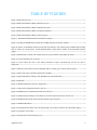
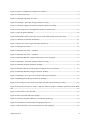
1
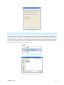
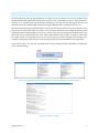
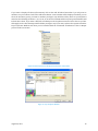
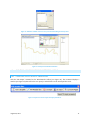
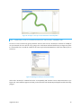
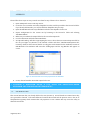
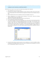
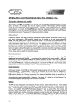
 RVRMEANDER–TUTORIALS
ArcGISVERSION
RobertoFernández1,DavideMotta2,JorgeD.Abad3,
EddyJ.Langendoen4,NilsOberg5,MarceloH.Garcia6
August29,2011
ABSTRACT
This document includes tutorials describing the possibilities of the RVR Meander Graphical User Interface
(GUI)developedforArcMap.EachtutorialshowsspecificcapabilitiesoftheGUIwhileguidingtheuserona
step‐by‐stepfashionfrominputtooutput.Atutorialbyitselfdoesn’tdescribeallthecomponentsoftheGUI.
DetaileddescriptionofeachoneisprovidedontheUser’sManual.
RVR Meander ßeta is in the public domain and is freely distributable. The authors and above organizations
assumenoresponsibilityorliabilityfortheuseorapplicabilityofthisprogram,noraretheyobligatedtoprovide
technicalsupport.
AuthorAffiliations:
1 Graduate Research Assistant, Dept. of Civil and Environmental Engineering, University of Illinois at Urbana‐
Champaign,Urbana,IL,61801.E‐mail:[email protected]
2 Graduate Research Assistant, Dept. of Civil and Environmental Engineering, University of Illinois at Urbana‐
Champaign,Urbana,IL,61801.E‐mail:[email protected]
3 Assistant Professor, Dept. of Civil and Environmental Engineering, University of Pittsburgh, Pittsburgh, PA,
15260.E‐mail:[email protected]
4 Research Hydraulic Engineer, US Department of Agriculture, Agricultural Research Service, National
SedimentationLaboratory,Oxford,MS,38655.E‐mail:[email protected]
5 Resident Programmer, Dept. of Civil and Environmental Engineering, University of Illinois at Urbana‐
Champaign,Urbana,IL,61801.E‐mail:[email protected]
6 Chester and Helen Siess Professor, Dept. of Civil and Environmental Engineering, University of Illinois at
Urbana‐Champaign.205N.MathewsAv.,Urbana,IL,61801.E‐mail:[email protected]
August29,2011
ii
TABLEOFCONTENTS
1. Introduction.............................................................................................................................................................................................1
2. InstallingtheRVRMeanderGraphicalUserInterface..........................................................................................................1
3. AddingtheRVRMeanderToolbarIntoArcMap......................................................................................................................2
4. Tutorial1:MackinawRiver,ILUSA;UsingTheMigrationCoefficientEmpiricalApproach...............................3
4.1.
Introduction.................................................................................................................................................................................3
4.2.
CreatingtheShapefiles(.shp)FromTextFiles(.txt).................................................................................................3
4.3.
OpenTheRVRMeanderGraphicalUserInterface(RVR‐GUI)...............................................................................4
4.4.
ImportingTheConfigurationFile.......................................................................................................................................5
4.5.
SelectingTheShapefilesForTheRunAndTheOutputFolder.............................................................................6
4.6.
RunSimulation...........................................................................................................................................................................7
4.7.
CreatingAndVisualizing1DOutputInArcMap...........................................................................................................8
4.7.1. CreatingThe1DOutputShapefile................................................................................................................................8
4.7.2. CustomizingTheVisualizationOfThe1DOutputShapefile.............................................................................9
4.8.
CreatingAndVisualizing2DOutputInArcMap.........................................................................................................11
4.8.1. CreatingThe2DOutputShapefiles............................................................................................................................11
4.8.2. CreatingATINToVisualizeSpecific2DOutputParameters..........................................................................15
4.8.3. CustomizongTheVisualizationOfTheTINCreatedForThe5YearsIterationAndTheParameter
“TAU” 17
5. Tutorial2:MackinawRiver,ILUSA;UsingThePhysically‐BasedApproach...........................................................18
5.1.
Introduction...............................................................................................................................................................................18
5.2.
SettingUpAndRunningASimulationWithThePhysically‐BasedApproach.............................................19
6. Tutorial3:MackinawRiver,ILUSA;UsingThePhysically‐BasedApproachAndFloodplainHeterogeneity
19
6.1.
Introduction...............................................................................................................................................................................19
6.2.
Setting Up and Running A Simulation With The Physically‐Based Approach And Floodplain
Heterogeneity............................................................................................................................................................................................20
6.3.
VisualizingFloodplainPropertiesInArcMap.............................................................................................................21
August29,2011
iii
7. ExampleOfPost‐ProcessedOutputUsingArcMap’sCapabilities..................................................................................22
A1.Appendix1:DescriptionOfTheParametersInTheOutputFiles...................................................................................24
August29,2011
iv
TABLEOFFIGURES
Figure1.RVR‐GUIsetupicon.....................................................................................................................................................................1
Figure2.RVR‐GUIInstallationWizard:WelcomeScreen.............................................................................................................1
Figure3.RVR‐GUIInstallationWizard:InstallationFolder.........................................................................................................1
Figure4.RVR‐GUIInstallationWizard:ConfirmInstallation......................................................................................................1
Figure5.RVR‐GUIInstallationWizard:SetupProgress................................................................................................................1
Figure6..RVR‐GUIInstallationWizard:InstallationComplete.................................................................................................1
Figure7.LoadingtheRVRMeandertoolbarintoArcMapusingtheCustomizewindow...............................................2
Figure8.Browsetoinstallationfolderandselectthefilewiththe“.tlb”extension(left).AddedObjectsdialog
will be shown on screen(center) and the RVR Meander Toolbar will be visible on the Customize window
(right)...................................................................................................................................................................................................................2
Figure9.RVRMeanderToolbarwith“ImageandText”(top)andwith“ImageOnly”(bottom)................................2
Figure10.Createshapefilefromatextfile..........................................................................................................................................3
Figure 11. Select either the river or the valley centerline to input. Currently only one file at a time is
supported............................................................................................................................................................................................................3
Figure12.Browsetothefolderwheretheshapefilewillbecreated,giveitanameandselectSave......................4
Figure13.RiverandvalleycenterlinesdisplayedinArcMap.....................................................................................................4
Figure14.OpenRVR‐GUIbyclickingontheRVRMeandercommandbutton....................................................................4
Figure15.RVR‐GUI..........................................................................................................................................................................................5
Figure16.RVR‐GUIFileMenu;ImportConfiguration....................................................................................................................5
Figure17.ImporttheConfigurationFilefortherun......................................................................................................................5
Figure18.RVR‐GUI;LayerDefinitiontabwithselectedlayers..................................................................................................6
Figure19.FolderBrowserDialogtoselectwheretosavetheOutputfilesforthecurrentrun..................................6
Figure20.RVR‐GUI;Outputtabwithaltheinformationrequiredinplace..........................................................................6
Figure21.RVR‐GUIRunMenu..................................................................................................................................................................7
Figure22.LogFileWatcherbeforetherun(left)duringarun(center)andaftertherunfinishes(right)...........7
Figure23.LogFilein.txt.format.............................................................................................................................................................7
Figure24.OutputFilescreatedduringtherun.................................................................................................................................8
August29,2011
v
Figure25.Importa1DOutputfileofMigratedCenterlines........................................................................................................8
Figure26.1DOututuserform...................................................................................................................................................................8
Figure27.1DOutputexpandeduserform..........................................................................................................................................9
Figure28.1DOutput–Statusbarmessageswhileprocessing..................................................................................................9
Figure29.1Doutput‐MigratedCenterlinesshapefileaddedintoArcMap.........................................................................9
Figure30.SelectPropertiesontheMigratedCenterline’scontextmenu............................................................................10
Figure31.LayerPropertiesWindow...................................................................................................................................................10
Figure32.AddValueswindow.SelecttheonesyouwantwhileholdingtheCtrlkeydown......................................11
Figure33.1DOutputcustomizedvisualization..............................................................................................................................11
Figure34.Opensuserformtoimport2DOutputparameters.................................................................................................11
Figure35.2DOutputuserform..............................................................................................................................................................12
Figure36.2DOutputuserform–expanded.....................................................................................................................................12
Figure37.2DOutputuserform–expanded.....................................................................................................................................12
Figure38.2DOutputWindowcompletedandreadytocreateshapefiles..........................................................................13
Figure39.2DOutput–Statusbarmessageswhileprocessing................................................................................................13
Figure40.2DOutputshapefileaddedintoArcMap.......................................................................................................................14
Figure41.AttributeTableforthe2DOutputincludingallselectedparameters.............................................................14
Figure42.2DOutputBoundaryPolygonaddedintoArcMap...................................................................................................14
Figure43.2DOutput–Closeuptoseethedetailofthecreatedshapefiles.......................................................................15
Figure44.Enablingthe3DAnalystextensionforArcMap.........................................................................................................15
Figure45.Accessingthe“CreateTinfromFeatures”windowwiththe3DAnalysttoolbar.......................................16
Figure46.RequiredparameterstoCreateaTINfromfeaturesusingthe2DOutputproducedwiththeRVR‐
GUI.......................................................................................................................................................................................................................16
Figure47.SelectfoldertoSavetheTIN..............................................................................................................................................16
Figure48.TINcreatedandaddedintoArcMap...............................................................................................................................17
Figure49.TINLayerPropertiesWindow–CustomizingSymbology.................................................................................18
Figure50.VisualizationoftheTINwhilechangingitsproperties..........................................................................................18
Figure51.Choosefilewithcrosssectionpropertiesforthesimulation..............................................................................19
August29,2011
vi
Figure52.Choosefilewithfloodplaindescriptionforthesimulation...................................................................................20
Figure53.FloodplainHeterogeneityand2DoutputshapefilesaddedintoArcMap......................................................21
Figure54.CreateaRasterusingtheIDWmethodfromthe3DAnalysttoolbar..............................................................21
Figure55.IDWparameterdefinitionwindowfortheFloodplainraster.............................................................................21
Figure56.FloodplainHeterogeneityRasterusingtheCriticalShearStressTauC.........................................................22
Figure57.Exampleofpost‐processedoutputusingRVR‐GUIandArcMap.......................................................................23
August29,2011
vii
1. INTRODUCTION
RVR Meander for ArcGIS is basically a toolbar that lets the user access forms to input parameters, run the
software andvisualize output inside ArcMap. It has been developed for ArcGIS9.3.1 and is currently being
testedonArcGIS10.0inordertosupportthenewestversionofESRI’ssoftware.TheRVRMeanderGraphical
User Interface (RVR‐GUI) provides different functionalities that facilitate the use of the RVR capabilities
availableforthestandaloneversioninsideArcMap.
Thismanualcontainsdifferentsectionsthatwillguidetheuseronastep‐by‐stepbasis.Itfirstdescribeshow
to install the RVR‐GUI and then shows the steps required to load its capabilities into ArcMap. Additional
sections are tutorialsdesignedto guidethe userthroughsometestcasesthat describe the useof the RVR‐
GUI’s components. Tutorials by themselves do not cover all the capabilities. Detailed description of all
componentsisprovidedintheUser’sManual.
2. INSTALLINGTHERVRMEANDERGRAPHICALUSERINTERFACE
Browsetothefolderwherethe“RVRMeander9.3.msi”fileissaved.Doubleclickontheicon(seeFigure1).
An installation wizard will appear on screen (see Figure 2). Click Next and specify the folder where RVR
Meanderwillbeinstalled(seeFigure3).ClickNextagainandontheconfirmationscreenclickNextagain(see
Figure 4). Installation will begin and the progress will be shown by the wizard (see Figure 5). Finally the
wizardwilldisplayamessagelettingtheuserknowthattheinstallationiscomplete(seeFigure6).
Figure1.RVR‐GUIsetupicon.
Figure3.RVR‐GUIInstallationWizard:InstallationFolder.
Figure2.RVR‐GUIInstallationWizard:WelcomeScreen.
Figure4.RVR‐GUIInstallation
Wizard:ConfirmInstallation.
August29,2011
Figure5.RVR‐GUIInstallation
Wizard:SetupProgress.
Figure6..RVR‐GUIInstallation
Wizard:InstallationComplete.
1
3. ADDINGTHERVRMEANDERTOOLBARINTOARCMAP
InsideArcMapopentheCustomizewindowlocatedintheToolsmenuandintheToolbarstabbrowseforthe
RVR Meander toolbar (see Figure 7). Ifthe toolbar isnotdisplayed clickon the “Addfrom file” button and
browse for the installation folder. Select the file with the “.tlb” extension and click “Open”. A new dialog
indicatingthe“AddedObjects”willappearonscreen.Click“OK”andintheCustomizewindowcheckthebox
to include the toolbar (see Figure 8). After clicking the “Close” button the toolbar will be displayed on the
ArcMapinterface(seeFigure9).
Figure7.LoadingtheRVRMeandertoolbarintoArcMapusingtheCustomizewindow.
Figure8.Browsetoinstallationfolderandselectthefilewiththe“.tlb”extension(left).AddedObjectsdialogwillbeshownon
screen(center)andtheRVRMeanderToolbarwillbevisibleontheCustomizewindow(right).
Figure9.RVRMeanderToolbarwith“ImageandText”(top)andwith“ImageOnly”(bottom).
August29,2011
2
4. TUTORIAL 1: MACKINAW RIVER, IL USA; USING THE MIGRATION COEFFICIENT
EMPIRICALAPPROACH
4.1.
INTRODUCTION
ThistutorialfortheMackinawRiverinIllinois,USApresentsastepbystepdescriptionregardingtheuseof
someofthecapabilitiesoftheRVRMeanderGUI.ItusestheMigrationCoefficientempiricalapproachwhich
isthesimplestavailabletogettheuserstarted.
Inordertorunthistutorialyouwillneedthefilesthatcamewiththeinstallation.IftheRVRMeandertoolbar
is not visible in ArcMap please add it. If you’re not sure on how to do it please refer to Section 3 of this
manual.
4.2.
CREATINGTHESHAPEFILES(.SHP)FROMTEXTFILES(.TXT)
Clickonthe“TexttoShapefile”commandbuttoninthetoolbar(seeFigure10).An“OpenFileDialog”willbe
displayedthatletsyoubrowsefortherequiredtextfile(seeFigure11).Thecurrentversionsupportsonly
onefileatatimeandthereforeyouneedtodotheprocesstwice.Firstselectthe“Mackinaw_River.txt”fileand
clickOpen.A“SaveFileDialog”willappearpromptingyoutoprovideanameandtospecifythefolderwhere
you wish to save the shapefile (see Figure 12). Click Save and it will be created and added into ArcMap.
Repeattheprocessforthe“Mackinaw_Valley.txt”file.TheresultshouldlookliketheonepresentedinFigure
13exceptforthecolorsthatmightlookdifferentonyourcomputer.
Figure10.Createshapefilefromatextfile.
Figure11.Selecteithertheriverorthevalleycenterlinetoinput.Currentlyonlyonefileatatimeissupported.
August29,2011
3
Figure12.Browsetothefolderwheretheshapefilewillbecreated,giveitanameandselectSave.
Figure13.RiverandvalleycenterlinesdisplayedinArcMap.
4.3.
OPENTHERVRMEANDERGRAPHICALUSERINTERFACE(RVR‐GUI)
Clickonthe“RVRMeanderßeta”commandbutton(seeFigure14)toaccesstheuserinterface.Anewwindow
willappear(seeFigure15).TheRVRGUIcontainseightdifferenttabsprovidedtoentertheinputparameters
for the run. Some parameters are set todefaultortypical values. Explorethe contents ofthedifferenttabs
andgetfamiliarwiththembeforecontinuingwiththistutorial.
Figure14.OpenRVR‐GUIbyclickingontheRVRMeandercommandbutton.
August29,2011
4
Figure15.RVR‐GUI.
4.4.
IMPORTINGTHECONFIGURATIONFILE
ClickontheFilemenuandselect“ImportConfiguration”(seeFigure16).An“OpenFileDialog”willappearon
screenpromptingyoutobrowsefortheconfigurationfile.Find“Tutorial_1_Data.txt”fileontheinstallation
folderandclickOpen(seeFigure17).Afterdoingso,allthetabsshouldbeautomaticallypopulatedaccording
totheparameterscontainedinthefilejustloaded.Ifyouarecuriousabouttheformatoftheconfigurationfile
importedyoucanfinditandopenitusingtheNotepad.
Figure16.RVR‐GUIFileMenu;ImportConfiguration.
Figure17.ImporttheConfigurationFilefortherun.
August29,2011
5
4.5.
SELECTINGTHESHAPEFILESFORTHERUNANDTHEOUTPUTFOLDER
Before running the simulation two more things are required. Go to the “Layer Definition” tab and in the
correspondingdropdownboxesselectthefilesfortheriverandthevalleycenterlines.Afterselectingthem
yourRVRMeanderinterfaceshouldlookliketheoneshowninFigure18.Gotothe“Output”tabandclickon
thebrowsebutton
to select the folder where you wish to save the output files. A “Browse Folder
Dialog”willappearonscreen(seeFigure19).SelectthefolderandclickOK.Inthiscase,anewfoldernamed
“Output_Run_1” was created. Now the “Output” tab should look like the one shown in Figure 20. You will
probablyhavedifferencesinthepathoftheoutputfolderbutthatisnotaproblem.Youarenowreadytorun
thesimulation.
Figure18.RVR‐GUI;LayerDefinitiontabwithselectedlayers.
Figure20.RVR‐GUI;Outputtabwithaltheinformation
requiredinplace.
Figure19.FolderBrowserDialogtoselectwheretosave
theOutputfilesforthecurrentrun.
August29,2011
6
4.6.
RUNSIMULATION
OpentheRunMenuandclick“RunSimulation”(seeFigure21).Ifeverythingiscorrectanewwindowcalled
Log File Watcher will appear that will show the progress of the computations as well as some parameters.
Once the run is completed, the Log File Watcher will display a message that says Exiting and the Save and
Closebuttonswillbeenabled.Figure22showstheLogFileWatcherbefore,duringandaftertherun.
TheresultsdisplayedontheLogFileWatcherarenotsavedunlessyoudecidetodoso.IfyouclickSaveyou’ll
needtobrowsetothefolderwhereyouwishtosavetheLogFileinformation.Anexampleofthisfileopened
withtheNotepadisshowninFigure23.Ifyouarecurioustoseehowtheoutputfileslooklikebrowsetothe
folderwhereyousavedthemandtakealook.Theirnameswillstartwith“TecPlot”(seeFigure24)because
the output format was originally created to be opened using that software package. The meaning of the
variablesisexplainedintheheaderlinesofthefileandisalsopresentedinthetablelocatedinAppendix1.
Ifyouhaven’tdonesoyetclosetheLogFileWatchertobegincreatingtheoutputshapefilestovisualizethe
run’sresultsinArcMap.
Figure21.RVR‐GUIRunMenu.
Figure22.LogFileWatcherbeforetherun(left)duringarun(center)andaftertherunfinishes(right).
Figure23.LogFilein.txt.format.
August29,2011
7
Figure24.OutputFilescreatedduringtherun.
4.7.
CREATINGANDVISUALIZING1DOUTPUTINARCMAP
4.7.1. CREATINGTHE1DOUTPUTSHAPEFILE
Click the “1D Output” command on the RVR Meander toolbar (see Figure 24). This command displays a
windowthatwillletyouspecifyinwhatfolderisthefilewiththeoutputinformationsaved(seeFigure25).
Figure25.Importa1DOutputfileofMigratedCenterlines.
Figure26.1DOututuserform.
Clickonthebrowsebutton
toselectthefolderwheretheoutputfilesfromthecurrentrunweresaved.
OnceyoudosothewindowwillexpandallowingyoutoFinishorCanceltheoperation(seeFigure27).Make
sureyoubrowsetothecorrectfolder.Ifyoudon’tawarningmessagewillletyouknowthatnooutputfiles
aresavedonthespecifiedlocation.ClickFinishtostartprocessingthe1DOutput.Whiletheprocessistaking
placemessageswillbedisplayedonArcMap’sstatusbar(bottomofthescreen)askingtheusertowaitfora
fewseconds(seeFigure28).ArcMap’sscreenwillfreezeforaninstantwhiletheprocesstakesplacebutwill
refreshassoonasitisfinished.Anewshapefilewillbeaddedintoyourmapcalled“MigratedCenterlines”
August29,2011
8
anditmighthaveadifferentcoloronyourmachinebutitshouldlooksimilartotheoneshowninFigure29
(otherlayerswereturnedofftoshowonlytheMigratedCenterlineslayer).
Figure27.1DOutputexpandeduserform.
Figure28.1DOutput–Statusbarmessageswhileprocessing.
Figure29.1Doutput‐MigratedCenterlinesshapefileaddedintoArcMap.
Beforegoingontothe2DOutputit’simportanttomodifythepropertiesoftheMigratedCenterlineslayerto
makeiteasiertovisualize.IfyoualreadyknowenoughofArcMaptodothiswithoutanyguidanceorarenot
interestedatthetimeproceedtosection4.8.Incaseyouwishtolearnhowtomodifyalayer’spropertiesfor
betterandcustomizedvisualizationreadthoroughlythenextsection.
4.7.2. CUSTOMIZINGTHEVISUALIZATIONOFTHE1DOUTPUTSHAPEFILE
RightclickontheMigratedCenterlineslayerandonitscontextmenuselectProperties(seeFigure30).Goto
theSymbologytabandontheleftpanecalledShowselectCategories–UniqueValues(seeFigure31).Make
surethatinthe“ValueField”theoptionYEARSisselectedandthatyouunchecktheboxcorrespondingtoall
othervalues.BeforegoingonmakesurethateverythinglookslikeFigure31.
August29,2011
9
If you want to display all values (all iterations) click on the Add All Values button but if you only want to
visualizeevery5iterationsclickontheAddValuesbutton.Anewwindowwillbedisplayedinwhichyoucan
selecttheiterations(years)youwanttovisualize(seeFigure32).HoldtheCtrlkeydownonyourkeyboard
andselectthefollowingiterations:5,10,15,20,25,30and35.ClickOKandtheLayerPropertiesWindowwill
includethesevalues.IfyouwantadifferentColorRampusethedropdownmenuandselecttheoneyoulike.
ClickApplyandseehowtheOutputwilllooklike(seeFigure33).Ifyouwant,exploreotheroptionsinsidethe
Layer Properties Window and when you feel satisfied with the customized visualization of the 1D Output
proceedtothenextsection.
Figure30.SelectPropertiesontheMigratedCenterline’scontextmenu.
Figure31.LayerPropertiesWindow.
August29,2011
10
Figure32.AddValueswindow.SelecttheonesyouwantwhileholdingtheCtrlkeydown.
Figure33.1DOutputcustomizedvisualization.
4.8.
CREATINGANDVISUALIZING2DOUTPUTINARCMAP
4.8.1. CREATINGTHE2DOUTPUTSHAPEFILES
Click the “2D Output” command on the RVR Meander toolbar (see Figure 34). This command displays a
window(seeFigure35)thatwilllettheuserspecifyinwhichfolderarethe2Doutputfilessaved.
Figure34.Opensuserformtoimport2DOutputparameters.
August29,2011
11
Figure35.2DOutputuserform.
Clickonthebrowsebutton
toselectthefolderwheretheoutputfilesfromthecurrentrunweresaved.
Once you do so the window will expand (see Figure 36) allowing you to select which parameters and for
whichiteration(seeFigure37)youwishtooutput.Makesureyoubrowsetothecorrectfolder.Ifyoudon’ta
warningmessagewillletyouknowthatnooutputfilesaresavedonthespecifiedlocation.
Select the T=5.000000 years iteration (see Figure 37) and also check the box that says Select All. This will
automatically select all the parameters that are available for output. The window should now look like the
one shown in Figure 38. Click Finish to start processing the 2D Output. While the process is taking place
messageswillbedisplayedonArcMap’sstatusbar(bottomofthescreen)askingtheusertowaitforafew
seconds (see Figure 39). ArcMap’s screen will freeze for an instant while the process takes place but will
refreshassoonasitisfinished.
Figure36.2DOutputuserform–expanded.
August29,2011
Figure37.2DOutputuserform–expanded.
12
Figure38.2DOutputWindowcompletedandreadytocreateshapefiles.
Figure39.2DOutput–Statusbarmessageswhileprocessing.
Two shapefiles will be added into your map called “2Dafter_T=5.000000_yrs.shp” and
“Boundary_After_T=5.000000_yrs”.Thefirstonecontainsthe2DOutputvaluesandismadeupofpoints(see
Figure40).Eachpointislocatedonagivencrosssectionandcontainsthevalueforthedifferentcomputed
parametersatthatspecificlocationinspace.ThevaluescanbeseenintheAttributeTableofthelayer.Ifyou
want to visualize it right click on the layer to display its context menu and select Attribute Table. A new
windowwillbedisplayed(seeFigure41)withallthevaluesfortheparametersthatwerecheckedinthe2D
OutputWindow.ThemeaningofthevariablescanbefoundinAppendix1.
The second layer is a boundary polygon for the corresponding iteration (see Figure 42). This boundary
polygonisnecessarytocreateaTINorRastertovisualizedifferentparametersinArcMap.Figure43showsa
close up view of the 2D output shapefiles. Display properties were changed for both layers (inside the
SymbologytaboftheLayerPropertieswindow).
August29,2011
13
Figure40.2DOutputshapefileaddedintoArcMap.
Figure41.AttributeTableforthe2DOutputincludingallselectedparameters.
Figure42.2DOutputBoundaryPolygonaddedintoArcMap.
August29,2011
14
Figure43.2DOutput–Closeuptoseethedetailofthecreatedshapefiles.
4.8.2. CREATINGATINTOVISUALIZESPECIFIC2DOUTPUTPARAMETERS
InordertocreateaTINforanygivenparametertheusermustusethe“3DAnalyst”extensionofArcMap.If
notyetactivated,theusermustdosobygoingtotheToolsMenuandthenExtensions(seeFigure44).Once
it’sactivatedtheusercanaddthetoolbarinthesamewaythattheRVRMeanderToolbarwasadded(referto
Section2).
Figure44.Enablingthe3DAnalystextensionforArcMap.
Clickonthe“3DAnalyst”commandandselect“Create/ModifyTIN”andthen“CreateTINFromFeatures”(see
Figure45).Anewwindowappearsinwhichyoushouldselectboththe2DOutputshapefileandtheboundary
polygon.
August29,2011
15
Figure45.Accessingthe“CreateTinfromFeatures”windowwiththe3DAnalysttoolbar.
YouwillcreateaTINfortheparameter“TAU”usingthe“5years”iterationandthecorrespondingboundary
polygon (see Figure 46). Note that for the 2D Output file the “Height source” for the TIN is the desired
parameter(“TAU”‐shearstressmagnitudeinthiscase)andinthecaseoftheboundarypolygontheoption
“None”shouldbeselectedaswellasthe“SoftClip”option.Usershouldalsospecifythenameandfolderto
savetheTIN(seeFigure47).Youcannameit“Shear_stress_magnitude_5yrs”orsimply“TAU_5yrs”.Donot
forgettousetheboundarypolygoninthecreationofTINs.NotusingitwillnotavoidcreatingtheTINbutit
willnotfollowtheriver’smigratedcenterline.Oncetheuserclick’s“OK”theTINwillbecreatedanddisplayed
inArcMap(seeFigure48).
Figure46.RequiredparameterstoCreateaTINfromfeaturesusingthe2DOutputproducedwiththeRVR‐GUI.
Figure47.SelectfoldertoSavetheTIN.
August29,2011
16
Figure48.TINcreatedandaddedintoArcMap.
ForvisualizationpurposesitmightbenecessarytomodifythepropertiesofthenewTIN.Ifyoualreadyknow
enoughofArcMaptodothiswithoutanyguidanceorarenotinterestedatthetimeyouaredonewiththis
tutorial.YoucansavethemapandcloseArcMap.IncaseyouwishtolearnhowtomodifytheTINsproperties
forbetterandcustomizedvisualizationreadthoroughlythenextsection.
4.8.3. CUSTOMIZONG THE VISUALIZATION OF THE TIN CREATED FOR THE 5 YEARS
ITERATIONANDTHEPARAMETER“TAU”
RightclickontheTIN(“Shear_stress_magnitude_5yrs”)toopenitscontextmenu.SelectthePropertiesoption
andgototheSymbologytab.YoumightwanttounchecktheEdgeTypesbox(leftpane)andgotoElevation.
TINs are generally created with 9 classes but less might make it easier to visualize. Therefore on the
dropdown menu for classes select 5. If you want you can uncheck the box to Show hillshade illumination
effectin2Ddisplay(bottomleft).MakesuretoclicktheApplybuttontoseewhateachchangedoestoyour
display. You may need to drag the Layer Properties Window to a place where it lets you see the TIN (see
Figure 50). Explore the possibilities (different color ramps, class numbers, effects, etc.) and when you feel
satisfiedwiththecustomizedvisualizationoftheTINclickOK.
August29,2011
17
Figure49.TINLayerPropertiesWindow–CustomizingSymbology.
Figure50.VisualizationoftheTINwhilechangingitsproperties.
You can repeat the process for different parameters or different iterations. Section 5 shows customized
visualization made with two different iterations and 3 different parameters. It also includes Floodplain
Heterogeneityvisualizationwhichwasn’texploredinthistutorial.Ifyouwanttoexplorethatoptionreferto
Tutorial3.
5. TUTORIAL 2: MACKINAW RIVER, IL USA; USING THE PHYSICALLY‐BASED
APPROACH
5.1.
INTRODUCTION
This tutorial assumes that you already did the first one (Section 4). Several details are omitted since they
were provided in Tutorial 1. The main difference between this tutorial and the previous one is the bank
erosionapproachusedforthecomputations.
August29,2011
18
5.2.
SETTING UP AND RUNNING A SIMULATION WITH THE PHYSICALLY‐BASED
APPROACH
Pleasefollowthesesteps.IncaseyouneedmoredetailonanyofthemrefertoTutorial1.
1.
2.
3.
4.
5.
6.
7.
OpenArcMapandcreateanewmap.Saveit.
CreatetherivercenterlineandvalleyshapefilesfromthetextfilesprovidedintheTutorial2folder.
IfyoualreadydidTutorial1youcanjustaddthoseshapefilesintoyourmap.
OpentheRVR‐GUIandintheLayerDefinitiontabselecttheshapefilesfortherun.
Import Configuration for the current run by browsing to the Tutorial 2 folder and selecting
“Mackinaw‐PB.txt”.
MakesureyouindicatetheoutputfolderfortherunintheOutputtab.
GototheRunmenuandclickonRunSimulation.
An“OpenFileDialog”willshowuppromptingtheusertochoosetheCrossSectionPropertiesfilefor
the run (see Figure 51). Browse to the Tutorial 2 folder and select “InitialSectionProperties.dat”.
Currently,detailsontheformatofthisfileareonlygiveninthemanualforthestandaloneversionof
RVR Meander. The simulation will start after clicking Open and the Log Watcher will appear on
screen.
Figure51.Choosefilewithcrosssectionpropertiesforthesimulation.
8.
Create,editandvisualize1Dand2Doutputfortherun.
6. TUTORIAL 3: MACKINAW RIVER, IL USA; USING THE PHYSICALLY‐BASED
APPROACHANDFLOODPLAINHETEROGENEITY
6.1.
INTRODUCTION
This tutorial assumes that you already did the first one (Section 4). Several details are omitted since they
were provided in Tutorial 1. The main difference between this tutorial and the previous ones is the use of
floodplain heterogeneity which assumes that soil properties are not constant and vary across the valley in
whichtheriverflows.
August29,2011
19
6.2.
SETTING UP AND RUNNING A SIMULATION WITH THE PHYSICALLY‐BASED
APPROACHANDFLOODPLAINHETEROGENEITY
Pleasefollowthesesteps.IncaseyouneedmoredetailonanyofthemrefertoTutorial1.
1.
2.
3.
4.
5.
6.
7.
OpenArcMapandcreateanewmap.Saveit.
CreatetherivercenterlineandvalleyshapefilesfromthetextfilesprovidedintheTutorial3folder.
Ifyoualreadydidprevioustutorialsandhavetheshapefilesathandyoucanjustaddthemintoyour
map.
OpentheRVR‐GUIandintheLayerDefinitiontabselecttheshapefilesfortherun.
Import Configuration for the current run by browsing to the Tutorial 3 folder and selecting
“Mackinaw‐PB‐HeterogeneousFloodplain.txt”.
MakesureyouindicatetheoutputfolderfortherunintheOutputtab.
GototheRunmenuandclickonRunSimulation.
Two“OpenFileDialogs”willshowuppromptingtheusertochoosetheCrossSectionPropertiesfile
for the run (see Figure 51) and the floodplain properties file (see Figure 52). First browse to the
Tutorial 3 folder and select “InitialSectionProperties.dat” and second go to the Heterogeneous
Floodplainfolderandselectanyoftheavailable“Grid.txt”files.Differentgridsizesareprovidedin
caseyouwanttoexploretheeffectofhavingmoreorlessdatadescribingthefloodplain.Detailson
thesetwotypesofinputfilesarecurrentlyonlyprovidedinthemanualforthestandaloneversionof
RVRMeander.
Figure52.Choosefilewithfloodplaindescriptionforthesimulation.
8.
Create, editand visualize 1D and 2D output forthe run. Make suretoselectthe checkbox to Show
Floodplaininthe2DOutputwindow.Ifyoudoso,afterthe2DOutputprocessingfinishesyoushould
havesomethingsimilartoFigure53onyourscreen.
August29,2011
20
Figure53.FloodplainHeterogeneityand2DoutputshapefilesaddedintoArcMap.
6.3.
VISUALIZINGFLOODPLAINPROPERTIESINARCMAP
The floodplain shapefile is also made up of points (as the 2D Output shapefile). Each point contains the
floodplainpropertiesatthatlocation.InordertovisualizethefloodplainpropertiesyoucanusetheSpatial
Analyst, the 3D analyst or even the Geostatistical Analyst to create a raster to show the properties. An
examplewillbeshownhereusingthe3DAnalysttoolbar(seeFigure54)tocreateafloodplainRasterusing
the “Inverse Distance Weighted – IDW” algorithm (see Figure 55). The parameter used is the critical shear
stress(TauC).TheresultingrasterwithsomemodificationsforbettervisualizationisshowninFigure56.
Figure54.CreateaRasterusingtheIDWmethodfromthe3DAnalysttoolbar.
Figure55.IDWparameterdefinitionwindowfortheFloodplainraster.
August29,2011
21
Figure56.FloodplainHeterogeneityRasterusingtheCriticalShearStressTauC.
7. EXAMPLEOFPOST‐PROCESSEDOUTPUTUSINGARCMAP’SCAPABILITIES
TheRVR‐GUIinArcMapallowsusingallthebuiltinfunctionalitieswhichisanaddedfuturefortheinterface.
Quality output can be made with some post processing effort with ArcMap’s tools. An example is shown
below(seeFigure57).
August29,2011
22
RVR Meander User Interface
Floodplain Heterogeneity
Basic Input
4
River Centerline
Valley Centerline
1D Output
Migrated
Centerlines (yrs)
0
20
5
25
10
30
15
35
Water Depth (m)
Velocity Magnitude (m/s)
2D Output
After 35 years
After 5 years
1.1 - 1.5
0.8 - 1.1
1.1 - 1.3
0.5 - 0.8
0.8 - 1.1
0.5 - 0.8
1.9 - 3.2
2.1 - 3.5
0.6 - 1.9
0.6 - 2.1
Shear Stress
Magnitude (Pa)
-0.8 - 0.6
-0.9 - 0.6
11.9 - 16.6
9.7 - 13.4
7.1 - 11.9
5.9 - 9.7
2.3 - 7.1
2.2 - 5.9
Figure57.Exampleofpost‐processedoutputusingRVR‐GUIandArcMap.
August29,2011
23
A1.APPENDIX1:DESCRIPTIONOFTHEPARAMETERSINTHEOUTPUTFILES
TableA1presentsasimpledescriptionofthedifferentvariablesproducedasOutputinRVRMeander.
TableA1.DescriptionofRVRMeanderoutputparameters.
1
2
3
4
5
6
7
8
9
10
11
12
13
14
15
16
17
18
19
20
21
22
23
24
Parameter
HH
DD
EE
H1
D1
E1
h
d
e
UU
VV
U1
V1
u
v
C
Theta
Ux
Vy
Vel
TauS
TauN
Tau
CF
Meaning
Water surface elevation
Water depth
Bed elevation
Water surface elevation perturbations
Water depth perturbations
Bed elevation perturbations
Dimensionless water surface elevation
Dimensionless water depth
Dimensionless bed elevation
Streamwise velocity
Transverse velocity
Streamwise velocity perturbations
Transverse velocity perturbations
Dimensionless streamwise velocity
Dimensionless transverse velocity
Curvature
Angle of curvature
Velocity in the "x" component
Velocity in the "y" component
Velocity magnitude
Streamwise shear stress
Transverse shear stress
Shear stress magnitude
Friction coefficient
August29,2011
24