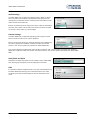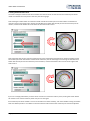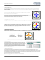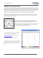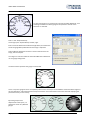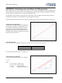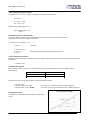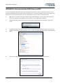
1
VIDEO VBOX LITE HARDWARE & SOFTWARE MANUAL Issue 1 22 December 2009 VIDEO VBOX LITE MANUAL This page intentionally left blank Page | 2 22 December 2009 VIDEO VBOX LITE MANUAL Introduction The Video VBOX LITE combines a powerful GPS data logger with a high quality solid-state video recorder, which takes multiple cameras and combines them with a graphical overlay, with the resulting video streamed onto an SD card as a DVD quality MPEG4 file. The Video VBOX LITE records the following parameters as standard along with the video file: satellites, time, latitude, longitude, velocity, heading, height, vertical velocity, and avisynctime. The VBOX Tools Software provided with the unit allows you to view the recorded video and analyse all of the parameters which have been logged, allowing you to see how fast you were going at any time, your maximum g-force, where you went using Google Earth and many other useful parameters. The logging rate of the Video VBOX LITE is 10 samples per second, which is good for capturing fast events like a sports car on a circuit, a downhill skier or even a mountain biker. As an example, an 8 Gigabyte High Capacity SD card logging video on the highest quality setting will be able to log approximately 160 minutes of video. NB: This is an approximation as the size of the recorded video will depend on what is being recorded. The movement, colour, and complexity of the subject matter will affect the size of the video file created. This guide enables you as a new Video VBOX LITE user to quickly get started and introduces you to key features of the hardware and software. It describes how to use the Video VBOX LITE and the Video VBOX LITE set up software. It describes the layout of the software and how it is used to configure the graphical overlay used when recording the video. The overlay Elements can be set up to display any of the channels logged by the Video VBOX LITE and the resultant video and VBOX data file are time synchronised to allow linked analysis of the data and video in the VBOX Tools software. Throughout this guide we will be referring to the following: Elements These are graphical representations of the VBOX channel data such as a speedometer gauge, a track map, or static graphics such as text labels or images. Elements make up the Scene which the Video VBOX LITE overlays onto the video. NB: An Element is exported out of the software with a .ELM extension. Scenes A Scene is the graphical overlay file created using the Video VBOX LITE setup software. The Scene is made up of Elements. When the Video VBOX LITE creates the video files, the Scene file determines how the final video is visualized. NB: A Scene is exported out of the software with a .SCN extension. NB: Please note that the instructions given in this manual relate specifically to the Video VBOX LITE. This product ships with a default graphical scene. To get more scenes free of charge please register your unit here: www.videovbox.co.uk/register Page | 3 22 December 2009 VIDEO VBOX LITE MANUAL Contents Introduction ........................................................................................................................................................................ 3 Contents ............................................................................................................................................................................. 4 Quickstart Guide ................................................................................................................................................................. 8 Video VBOX LITE Overview ............................................................................................................................................... 10 Video VBOX LITE Inputs and Outputs ........................................................................................................................... 10 What can you do with the Video VBOX LITE? ............................................................................................................... 10 What can you customise on the Video VBOX LITE? ...................................................................................................... 10 Software Installation ..................................................................................................................................................... 11 Video VBOX LITE Registration ....................................................................................................................................... 11 Getting Started with your Video VBOX LITE ..................................................................................................................... 12 Connections .................................................................................................................................................................. 12 LED Indicators ........................................................................................................................................................... 12 Displaying Data with the OLED display ............................................................................................................................. 13 VVBL Data Logging ............................................................................................................................................................ 14 Standard Channels ........................................................................................................................................................ 14 Single CAN channel Logging .......................................................................................................................................... 14 Lap-Timing Parameters ................................................................................................................................................. 14 DriftBox Parameters ..................................................................................................................................................... 14 MPEG4 Video ................................................................................................................................................................ 15 Interlaced Video ........................................................................................................................................................ 15 Logging Modes .............................................................................................................................................................. 16 Logging Rates ................................................................................................................................................................ 16 File Management .......................................................................................................................................................... 16 Logged File Format ....................................................................................................................................................... 17 Logging a CAN channel ..................................................................................................................................................... 18 Loading a CAN Database from Scene Properties .......................................................................................................... 18 Loading a CAN Database from Element Properties ...................................................................................................... 20 Advanced CAN Options ................................................................................................................................................. 21 CAN Baud Rate .......................................................................................................................................................... 21 CAN Mode ................................................................................................................................................................. 21 Page | 4 22 December 2009 VIDEO VBOX LITE MANUAL Manual Editing of CAN Parameter Fields .................................................................................................................. 21 Assigning the CAN parameter to an Element ............................................................................................................... 22 Connecting to the Vehicle CAN Bus .............................................................................................................................. 22 Configuring the Video VBOX LITE to use a Micro/Mini Input Module .......................................................................... 23 Selecting Input Module channels for use with the Video VBOX LITE ....................................................................... 23 Setting up a MIM for use with the Video VBOX LITE ................................................................................................ 24 Displaying Lap-Timing Parameters ................................................................................................................................... 24 Creating Start / Finish Lines and Splits .......................................................................................................................... 25 Creating Circuit Overlays .............................................................................................................................................. 27 Displaying DriftBox Parameters ........................................................................................................................................ 28 Performing a GPS Engine Coldstart................................................................................................................................... 28 Software Overview ........................................................................................................................................................... 29 Recommended Software Tools ..................................................................................................................................... 29 Starting the Video VBOX LITE Setup Software .................................................................................................................. 30 The Main View Window ................................................................................................................................................ 31 The Browser Window ................................................................................................................................................... 31 The Properties Window ................................................................................................................................................ 31 The Menu Bar ............................................................................................................................................................... 32 File ............................................................................................................................................................................ 32 Elements ................................................................................................................................................................... 33 Video ......................................................................................................................................................................... 33 Options ..................................................................................................................................................................... 33 Scenes ............................................................................................................................................................................... 34 Creating a New Scene ................................................................................................................................................... 34 Selecting an Existing Scene ........................................................................................................................................... 34 Modifying Scene Properties .......................................................................................................................................... 35 Grid Set-Up ............................................................................................................................................................... 35 Video VBOX LITE Type ............................................................................................................................................... 35 Serial Application ...................................................................................................................................................... 35 Log Rate .................................................................................................................................................................... 35 Video Settings ........................................................................................................................................................... 35 Page | 5 22 December 2009 VIDEO VBOX LITE MANUAL Audio Settings ........................................................................................................................................................... 36 Camera Settings ........................................................................................................................................................ 36 Start/Finish and Splits ............................................................................................................................................... 36 CAN ........................................................................................................................................................................... 36 Adding Elements to a Scene ......................................................................................................................................... 37 The Elements Tab ..................................................................................................................................................... 37 Theme Drop-Down ................................................................................................................................................... 37 Element Type Drop-Down ........................................................................................................................................ 37 Controlling Layers in a Scene ........................................................................................................................................ 38 Ordering Layers in a Scene ....................................................................................................................................... 38 Grouping and Moving Elements/Layers in a Scene .................................................................................................. 39 Saving the Scene ........................................................................................................................................................... 41 Uploading a Scene to the Video VBOX LITE .................................................................................................................. 42 Using the Software ................................................................................................................................................... 42 Using the SD Card ..................................................................................................................................................... 42 Downloading a Scene from the Video VBOX LITE ......................................................................................................... 42 Exporting a Scene from the Software to a .SCN File ..................................................................................................... 42 Importing a Scene from a .SCN File .............................................................................................................................. 42 Elements ........................................................................................................................................................................... 43 Creating New Elements ................................................................................................................................................ 43 Selecting Element Size .............................................................................................................................................. 43 Video Picture-in-Picture ............................................................................................................................................ 44 Gauge ........................................................................................................................................................................ 45 Single Bar Graph ....................................................................................................................................................... 49 Double Bar Graph ..................................................................................................................................................... 51 Track Map ................................................................................................................................................................. 53 Text ........................................................................................................................................................................... 54 Using lap-timing parameters .................................................................................................................................... 55 Static Label ................................................................................................................................................................ 57 Static Images ............................................................................................................................................................. 58 Saving Newly Created Elements ................................................................................................................................... 59 Page | 6 22 December 2009 VIDEO VBOX LITE MANUAL APPENDIX 1: Basic Gauge Creation ................................................................................................................................... 60 APPENDIX 2: Calculating scale and offset of a CAN parameter ........................................................................................ 69 APPENDIX 3: How to upgrade the Video VBOX LITE firmware ......................................................................................... 71 APPENDIX 4: How to install the USB Drivers in VISTA ...................................................................................................... 72 APPENDIX 5: Troubleshooting Guide ................................................................................................................................ 76 APPENDIX 6: Video VBOX LITE Specification ..................................................................................................................... 79 Outputs and Accuracies ................................................................................................................................................ 79 Graphics, Sound and Storage ........................................................................................................................................ 81 Inputs ............................................................................................................................................................................ 82 Environmental and Physical .......................................................................................................................................... 82 Software........................................................................................................................................................................ 82 CAN Output ................................................................................................................................................................... 83 Unit Dimensions............................................................................................................................................................ 84 Connector Assignments ................................................................................................................................................ 85 Contact Details .................................................................................................................................................................. 87 Document Updates ....................................................................................................................................................... 87 Page | 7 22 December 2009 VIDEO VBOX LITE MANUAL Quickstart Guide A default scene is loaded as standard. To access free scenes, please register your unit here: www.videovbox.co.uk/register 1. Mount the GPS antenna in the centre of your vehicle’s roof, away from roof bars or radio aerials which can cause interference. NOTE: If there is no metal underneath the antenna, you need to create a metallic “ground plane” to get the most reliable satellite lock. Pictured is an example of an antenna mounted on a bike helmet using two layers of Aluminium Foil to block un-wanted ground reflections. 2. Push the antenna plug into the 'GPS' socket. 3. Insert the ‘PWR’ connector and screw the metal ring to lock in place. Then plug the cigarette lighter adapter into your vehicle. NOTE: The Video VBOX Lite will take about 35 seconds to start, at which point the unit will beep to indicate it has booted up. 4. Securely attach the forward facing camera (marked HI RES) to the windscreen of your car and, if required, place the Picture-in-Picture camera (marked LOW RES) so that it faces the driver. Use the line on the top of the camera to make an approximate alignment. For better alignment, either use the optional preview monitor, or the software preview function using a USB connected laptop (see manual). NOTE: Make sure the camera marked HI-RES is connected to the ‘CAM1’ socket, and the one marked LOW RES in the ‘CAM2’ socket. 5. Page | 8 A mono microphone is supplied as standard; plug this into the ‘MIC’ input. A stereo microphone can also be plugged in to the same socket if required. 22 December 2009 VIDEO VBOX LITE MANUAL 6. When a memory card has been inserted, the unit will beep and the ‘STATUS’ LED will illuminate. 7. Place the vehicle so the antenna has a clear view of the sky, it will take up to two minutes to acquire satellite lock, at which point the ‘GPS’ LED will illuminate. If you are in an open area, and you are still having trouble gaining lock, press and hold the RECORD button for 10 seconds, this will perform a ‘cold start’. 8. The default recording mode is ‘record only when moving’. Once satellite lock has been obtained, the unit will start recording every time the vehicle goes above 2.5km/h and stop when the speed has been less than 2.5km/h for 5 seconds. 9. You can override this setting and toggle the recording by pressing the ‘RECORD’ button. To go back into ‘Record only when moving’ mode, either re-boot the box, or re-insert the SD card. IMPORTANT SD Card Removal NEVER eject the SD card if the ‘RECORD’ LED is showing, you will lose video. To stop recording, either come to a halt, press the ‘RECORD’ button or disconnect the power (the internal ‘tank circuit’ will stop the recording and safely shut down the file). Using the Supplied USB Cable When connecting the Video VBOX to your computer, make sure you are using the Mini-USB to USB cable supplied with the unit. Other leads, for example those supplied with USB card readers, do not have a standard length USB connector and will completely prevent communication between your PC and the Video VBOX LITE and in some cases may cause the USB port on your computer to lock up. Mobile Phone Software Ensure that you shut down any mobile phone software running on your computer before connecting your Video VBOX LITE. Racelogic are aware of conflicts which can arise when using this software that interfere with the normal USB communication between your Video VBOX LITE and the USB port of your computer. Page | 9 22 December 2009 VIDEO VBOX LITE MANUAL Video VBOX LITE Overview Video VBOX LITE Inputs and Outputs What can you do with the Video VBOX LITE? Simultaneously log 2 camera inputs, with user configurable picture in picture and audio input Measure your speed, distance and other parameters Analyse your driving line Compare your driving style with others See if you are making the most of your tyres during braking and cornering Plot your route on Google Earth Measure your acceleration figures, top speed, ¼ mile etc. What can you customise on the Video VBOX LITE? User configurable graphical overlays – logos, gauges, bar graphs, circuit plots, lap times, distance, text and more. Additional features SD card Interface USB 2.0 interface for set-up and logging MPEG4 encoding – approximately 3 GB per hour DVD quality, PAL/NTSC format 10 GPS channels logged and displayed 1 CAN channel logged and displayed Lap-timing Parameter display DriftBox Parameter display LED operational status indication Tank Circuit - Provides power for approx. 15 seconds in the event of a supply outage to the VVB LITE Tough but lightweight plastic enclosure Page | 10 22 December 2009 VIDEO VBOX LITE MANUAL Storage Media & AV Cameras The Video VBOX LITE stores logged data onto an SD card. The SD cards available from Racelogic are already optimised for use on the Video VBOX LITE and as such do not need formatting before use. Should the SD Card need formatting due to card errors it can be done through Windows, as the Video VBOX LITE supports the following format type: FAT32 Racelogic strongly recommends the following media card brands: SanDisk Kingston Software Installation The Video VBOX LITE setup software must be installed onto the hard drive of a computer; it cannot be run from the installation CD. NB: The Video VBOX LITE setup software requires Microsoft .NET Framework 3.5 Service Pack 1 or higher to run. The installation CD contains the required .NET installation package. NB: In order to play back the AVI files recorded by the Video VBOX LITE, the XVid Codec pack must also be installed. The installation CD contains the required installation package. To install the software insert the CD into the CD drive of your computer. The default installation language is English. Press ‘OK’ to continue, then follow the on-screen instructions to complete the installation. The Video VBOX LITE setup software is not limited to one user or computer and can be installed on multiple workstations if so desired. Video VBOX LITE Registration So that Racelogic can continue to provide you with notification of the latest software releases, firmware upgrades and to offer technical support, please register your Video VBOX LITE. Please register your unit here: www.videovbox.co.uk/register Or fill out the supplied registration form and return it to Racelogic. Page | 11 22 December 2009 VIDEO VBOX LITE MANUAL Getting Started with your Video VBOX LITE Connections Included with the Video VBOX LITE is a cigar lighter power cable, which is the primary source of power input. This is terminated in a 2-way connector and mates with the 2-way ‘PWR’ socket on the Video VBOX LITE. The supplied GPS antenna with the gold MCX connector at the end of the antenna cable connects directly to the ‘GPS’ connector on the Video VBOX LITE. For more information about the GPS antenna and placement see the ‘GPS Antenna placement’ section in the troubleshooting guide. You must connect the GPS antenna before connecting power to the Video VBOX LITE. This is necessary because on power-up the Video VBOX LITE will look for a connected GPS antenna and automatically adjust its gain for optimum performance. LED Indicators There are a series of LED indicators on the front panel of the Video VBOX LITE, their functionality is as follows: POWER: Solid GREEN indicates power is connected. STATUS: Solid GREEN indicates SD card is inserted, camera is connected and the VVB LITE is ready to log. GPS: Flashing GREEN indicates a Coldstart is being performed. Off indicates no satellite lock has been attained. Solid GREEN indicates a valid position fix. RECORD: Off indicates the Video VBOX LITE is waiting to write data to the card. Solid GREEN indicates the Video VBOX LITE is logging to the SD card IMPORTANT: Never remove an SD card if this LED is on or flashing – you will lose video. Page | 12 22 December 2009 VIDEO VBOX LITE MANUAL Displaying Data with the OLED display For more information on the VVBL Setup Software see the section ‘Starting the Video VBOX LITE Setup Software’. The Video VBOX LITE is compatible with the OLED display which can be used to display Speed, Max Speed, Lap-time, and Lateral and Longitudinal Acceleration data from the Video VBOX LITE. If the Video VBOX LITE is to be used with the OLED, make sure the ‘OLED Display’ option is selected in the ‘Serial Application’ menu in Scene properties. When the Video VBOX LITE has completed initialisation the OLED detects whether the Video VBOX LITE has any Start/Finish & Split lines set in the current scene, if so the Video VBOX LITE defaults to using these Start/Finish & Split lines. An acknowledge message will appear on the OLED display to indicate successful transfer of Start/Finish & Split data to the OLED. The OLED will also default to the last mode used, so if you have set Start/Finish & Split lines in the scene and the OLED was last used for lap-timing, the OLED will automatically display the lap-timing information for the current track. Entering the OLED menu and selecting ‘Use OLED Display Splits Info’ will allow the user to define separate Start/Finish & Split lines for display by the OLED. The user can set a Start/Finish line on the fly by pressing the button. The user then has the choice of defining Split lines or skipping this stage. NB: If the OLED is to be used in conjunction with the Video VBOX LITE for lap-timing or logging control, make sure the ‘AUX’ cable is connected up to the correct socket on the OLED. The OLED (RLVBDSP04) only has serial on the topmost socket (when looking at the OLED with the buttons on the left hand side: see below) and will therefore only display lap times correctly and control VVB logging when connected this socket. The OLED (RLVBDSP04) has pass through CAN on both sockets and can be connected to external CAN devices on either of these ports. (The RLVBDSP05 model OLED does not have pass through CAN) Page | 13 22 December 2009 VIDEO VBOX LITE MANUAL VVBL Data Logging The Video VBOX LITE logs 10 standard channels along with the MPEG4 Video. Standard Channels The following channels are always logged to the VBO file: Satellites UTC Time Latitude Longitude Velocity Heading Height Vertical Velocity Avifileindex Avisynctime The following additional derived channels are also available for selection in the analysis software: Lateral Acceleration Longitudinal Acceleration Radius of Turn Time Since Stationary Time Since Power-Up For more information on how to display standard channels in the video overlay see the ‘Elements’ Section. Single CAN channel Logging It is possible to load a CAN database into the software which allows the logging of one CAN parameter and the use of the CAN parameter in the Video Overlay: 1 CAN channel (Video VBOX LITE models RLVBVD10LT, RLVBVD10LT1, and RLVBVD10LT2) For more information on how to log the CAN parameter and use them in the video overlay see the ‘Logging CAN Parameter’ Section. Lap-Timing Parameters It is possible to use 19 different lap-timing parameters as the input to a Text Element. This allows the visualisation of various timing parameters in the video overlay. For more information on how to display Lap-Timing parameters in the video overlay see the ‘Displaying lap-timing Parameters’ Section. DriftBox Parameters If a Racelogic DriftBox or VBOX Mini is available, it is possible to connect the unit to the Video VBOX LITE using a RLCAB090 serial cable and use the Drift Angle and Score parameters as input to elements within a Scene. For more information on how to display Drift Angle or Score in the video overlay see the ‘Displaying DriftBox Parameters’ Section. Page | 14 22 December 2009 VIDEO VBOX LITE MANUAL MPEG4 Video The Video VBOX LITE records interlaced MPEG 4 AVI Files. NB: It is not possible to record video when the Video VBOX LITE is connected to a computer. If the ‘Rec’ button is pressed whilst connected to a computer via USB the Video VBOX LITE will produce a warning beep. Interlaced Video There are two methods of recording and displaying video footage: interlaced scan and progressive scan. At the moment, the only bullet cameras you can buy use interlaced video: • Interlaced scan: This technique uses two fields to create a frame. One field contains all the odd lines in the image, the other contains all the even lines of the image. A PAL based television display, for example, scans 50 fields every second (25 odd and 25 even). The two sets of 25 fields work together to create a full frame every 1/25th of a second, resulting in a display of 25 frames per second. • Progressive Scan: This technique displays video by drawing all the lines of each frame in sequence. It is used for most cathode ray tube (CRT) computer monitors, all LCD computer monitors, and most HDTVs as the display resolutions are progressive by nature. (Other CRT-type displays, such as SDTVs, typically display interlaced video only) The Video VBOX LITE creates interlaced MPEG4 AVI format video files. Interlaced video is designed to be captured, stored and displayed in the same interlaced format. Because each frame of interlaced video is composed of two fields that are captured at different moments in time, interlaced video frames will exhibit motion artefacts if the recorded objects are moving fast enough to be in different positions when each individual field is captured. These artefacts may be more visible when interlaced video is displayed at a slower speed than it was captured or when still frames are presented. Because modern computer video displays are progressive scan systems, interlaced video will have visible artefacts when it is displayed on computer systems when there is a fast moving object in the frame. Computer systems are frequently used to edit video and this disparity between computer video display systems and television signal formats means that the video content being edited cannot be viewed properly unless separate video display hardware is utilized. NB: If the video recorded by the Video VBOX LITE is played out to a television capable of displaying an interlaced source the interlacing is not visible and the quality is exceptional. Replaying the recorded video on a CRT or LCD monitor may require software filters to be applied to smooth out the interlacing otherwise objects in the video will appear ‘combed’ or jagged. If the video is to be played back on a progressive scan monitor (ie. computer) then mounting the main video camera pointing directly forwards out of the car reduces the frame to frame differences and the interlacing effects are reduced if playing back on a computer. The video bitrate is also better utilised recording detail instead of motion blur, as video bitrate varies tremendously depending on what is being recorded. Windows Media Player does not render the video as well as other media players, Racelogic recommend the free to download VLC player (http://www.videolan.org/vlc/) as the quality of the rendered video is much higher. VLC player also has the ability to enable a de-interlacing filter (Video De-Interlace Blend). For a detailed explanation of interlacing also see here: www.100fps.com Page | 15 22 December 2009 VIDEO VBOX LITE MANUAL Logging Modes The Video VBOX LITE supports two logging modes, they are as follows: Log Only When Moving. This is the default setting of the Video VBOX LITE. The VBOX will automatically start logging data once it detects movement greater than 2.5 km/h, and will stop recording when the speed drops below 2.5km/h, or the ‘RECORD’ button is pressed. (If the button is pressed to stop logging the box will then be in manual logging mode, see below). NB: The minimum speed at which the Video VBOX LITE starts and stops logging is configurable and can be changed under the ‘Log Settings’ drop down in the scene properties in the Video VBOX Setup Software. The length of time the box waits when this speed is reached before closing the file can also be configured. See the ‘Scene Properties’ section for a more detailed description. Manual Logging. To enable manual logging, press the ‘RECORD’ button on the front of the unit. When this is done the Green ‘RECORD’ LED comes on and the Video VBOX LITE will log data until the logging button is pressed again or the media runs out of space. To return the box to ‘Log only when moving’ the media needs to be removed then replaced. The Video VBOX LITE will then have reverted back to log only when moving mode and will begin to log immediately if the vehicle is still moving, or if the vehicle is stopped, when the vehicle moves away again. NB: If the card is removed while the Video VBOX LITE is writing data to it, there is a risk that the data file may be corrupted resulting in loss of video data or a corrupt video file. As a default ‘Log only when moving’ is the logging mode selected, make sure to wait a short time after the vehicle has stopped for logging to finish. When this happens the unit will beep and the green ‘RECORD’ light will go off. If ‘Log continuously’ is selected, press the ‘RECORD’ button on the front of the unit. This will ensure that the current file is closed and will help to safeguard against data corruption. If the power supply to the box is removed before this happens, the tank circuit will provide power for approximately 15 seconds and close the current video file correctly. Logging during Low Power. e.g. Cranking: When the Video VBOX LITE is logging it is capable of detecting when the voltage supply has dropped to a level at which it is unable to provide power to the video cameras. At this point the box will emit a warning beep and a low power symbol will flash at the centre of the recorded video. If nominal power is regained within 5 seconds the box will stop beeping and continue to log. If power is not regained the current video file will be closed. If after a period of time power is regained a new video file will be created and logging will continue. Logging Rates The Video VBOX LITE logs data at a fixed rate of 10Hz (10 samples per second). File Management The Video VBOX LITE will log to a FAT32 formatted SD card. The Video VBOX LITE will search for and detect a newly inserted card and record to the newly connected device when the vehicle moves or the logging button is pressed. A new video (AVI) and data (VBO) file are created in a ‘media’ folder on the SD card every time the vehicle begins to move or the ‘REC’ button is pressed. The current files are closed when the vehicle comes to a stop or the ‘REC’ button is pressed again. The filename format is as follows: VBOX####.VBO, where #### represents an incrementing number. NB: If the size of the video file reaches 2 Gb it will be closed and a new file will be opened. This is due to a 32 bit file indexing limitation which prevents the creation of files bigger than approx 4Gb. The 2Gb size also makes the recorded video files large enough to cover the length of most races without a new file being opened. Page | 16 22 December 2009 VIDEO VBOX LITE MANUAL Logged File Format Video VBOX LITE files are saved in a Racelogic space delimited text format. This format is compatible with Performance Tools and VBOX Tools and can be easily imported into third party applications such as word processors or spreadsheets. Each file contains a header section before the main data that describes the channel content and information about the Video VBOX LITE, such as serial number and firmware version. The [column names] section specifies the data in each column of the data section. An example of a Video VBOX LITE .VBO file is shown below. NB: The “File created” time and date is derived from UTC time and date, so will not reflect your local time. File created on 14/09/109 @ 16:24:38 [header] satellites time latitude longitude velocity kmh heading height vertical velocity m/s avifileindex avisynctime [channel units] [comments] Video VBox (c) Racelogic Ltd Video VBox Version : 002.002.00000 General Release Lite Serial number : 011358 [laptiming] Start 59.39148 3119.19091 59.40020 3119.19443 ¬ Split 59.22593 3119.15592 59.24026 3119.15712 ¬ Split 59.00605 3119.22063 59.00951 3119.21784 ¬ Split 59.06469 3119.32464 59.06773 3119.32034 ¬ Split 58.99396 3119.35256 58.99286 3119.34767 ¬ Split 59.32845 3119.34939 59.31972 3119.35026 ¬ Split 59.47089 3119.27912 59.46281 3119.28130 ¬ [avi] VBOX [column names] sats time lat long velocity heading height vert-vel avifileindex avitime [data] 007 162447.50 003119.36375 000059.50834 019.347 262.88 +00147.19 +000.33 0001 -00000001 007 162447.60 003119.36364 000059.50882 019.737 259.23 +00147.18 +000.32 0001 -00000001 007 162447.70 003119.36350 000059.50932 019.913 255.23 +00147.20 +000.31 0001 000000080 007 162447.80 003119.36334 000059.50981 020.325 251.82 +00147.21 +000.32 0001 000000160 007 162447.90 003119.36317 000059.51030 020.583 247.92 +00147.23 +000.32 0001 000000280 007 162448.00 003119.36296 000059.51078 020.930 243.87 +00147.23 +000.32 0001 000000360 006 162448.10 003119.36274 000059.51125 021.194 239.82 +00147.26 +000.33 0001 000000480 006 162448.20 003119.36250 000059.51170 021.593 235.65 +00147.29 +000.35 0001 000000560 006 162448.30 003119.36224 000059.51213 021.845 232.14 +00147.33 +000.36 0001 000000680 006 162448.40 003119.36197 000059.51254 022.283 228.84 +00147.37 +000.37 0001 000000760 006 162448.50 003119.36169 000059.51295 022.625 225.99 +00147.40 +000.38 0001 000000840 Page | 17 22 December 2009 VIDEO VBOX LITE MANUAL Logging a CAN channel To log CAN with the Video VBOX LITE the CAN channel in the Video VBOX Setup Software must first be configured with the relevant CAN parameter field. This can be done by either loading a CAN database into the software and selecting the required channel or by manually setting up the CAN channel fields. If this step is not performed, no CAN channel will be listed for selection under the ‘CAN’ parameters drop-down list when building an Element. NB: All Video VBOX LITE models are capable of logging a single CAN channel, checking the VCI check box will have no effect on the CAN setup of the Video VBOX LITE. Loading a CAN Database from Scene Properties The CAN database can be any of the following formats: .DBC .REF .VCI 1. The database file can be loaded by expanding the ‘CAN’ tab in the Scene properties bar and clicking the ‘Load’ button. Until the CAN channel has been selected from a CAN database file, or manually configured, the buttons will show ‘Empty’ and no CAN channel will be available for use in the Scene. CAN Database File Racelogic Encrypted File Racelogic VCI File NB: The example on the right shows the empty CAN channel of a Video VBOX LITE. 2. The user has the option of loading the Racelogic supplied Vehicle CAN Database, a Racelogic Module database, their own CAN database file, or cancelling the load operation. 2a. Racelogic Vehicle CAN database If the user opts to load the Racelogic Vehicle CAN database, a file browser window opens giving the user the choice of loading either the full vehicle CAN dataset, or the RPM only dataset. The Full vehicle CAN dataset is an encrypted database containing all current vehicle CAN information held by Racelogic. The RPM only dataset contains only the RPM parameters from the Full vehicle dataset. Once the database has been chosen the parameter selection window opens (shown below, step 3). This contains a full list of all parameters contained within the selected Racelogic Vehicle CAN database file. NB: The Video VBOX LITE CAN database is in a Racelogic encrypted .REF format which means the parameter fields will not be viewable or editable in Advanced Options. NB: The CAN database file is being continually updated with new vehicle parameters all the time, if you cannot find CAN parameters for your vehicle get in touch with us here at Racelogic and we’ll see what we can do. Page | 18 22 December 2009 VIDEO VBOX LITE MANUAL 2b. Racelogic Module CAN database e.g. Mini Input Module If the user opts to load the Racelogic Module CAN database, a file browser window opens giving the user the choice of loading any of the Racelogic Module CAN datasets. Once the database has been chosen the parameter selection window opens (shown below, Step 3). This contains a full list of all parameters contained within the Racelogic Module CAN database file. 2c. Load .dbc File If the user opts to load their own CAN .dbc database file a file browser window opens and you must first navigate to the directory where the CAN database has been saved, select the file and click ‘OK’. 3. Once the CAN database has been selected, the user must then choose the CAN parameter to be used by the Video VBOX LITE. Clicking on the parameter name will list the CAN parameter field information to the right of the window. By ticking the checkbox next to the required CAN parameter, that parameter will be assigned to the empty channel. To select the checked channel click apply. 4. The channel will be populated with the selected CAN parameter, and the CAN channel button will now display the name of the parameter assigned to the channel. 5. The channel has now been configured for use in a Video VBOX LITE Scene. 6. To change the parameter assigned to a channel, click the channel button. This brings up the channel settings box. A different channel can be selected from the currently loaded CAN database file by double clicking on the parameter or single clicking and selecting apply, or the parameter fields can be edited directly by clicking the ‘Advanced Options’ drop-down. Page | 19 22 December 2009 VIDEO VBOX LITE MANUAL Loading a CAN Database from Element Properties 1. The database file can also be loaded by selecting ‘CAN and Modules’ from the Parameter drop-down in Element properties. An ‘Edit CAN Settings’ button will then appear at the bottom of the parameter selection window. NB: If the CAN channel have already been selected from the Scene properties, loading a CAN database file from this button will add the selected CAN channel to the next available slot. 2. The user now has the option of loading the Racelogic provided Video VBOX LITE CAN Database, their own CAN .dbc database file, or cancelling the load operation. 3. Once the CAN database has been selected, the user must then choose which CAN parameter is to be used by the Video VBOX LITE. Clicking on the parameter name will list the CAN parameter field information to the right of the window. By ticking the checkbox next to the required CAN parameter, that parameter will be assigned to the next empty channel available in the same order it is selected. e.g. WSPD_1 will be assigned to channel 1 if checked first. To select the checked channel click apply. 4. The CAN channel is now configured for use and will be available for selection from the parameter selection drop-down in element properties. Page | 20 22 December 2009 VIDEO VBOX LITE MANUAL Advanced CAN Options CAN Baud Rate The default Baud rate of the Video VBOX LITE is set at 500 Kbit, the user has the option of selecting 125, 250, 500, and 1MBit. CAN Mode There are two CAN modes available for selection under the Mode dropdown in CAN and Module Configuration: VCI The ‘VCI’ CAN mode should be selected if the Video VBOX LITE is to be connected to a third party CAN bus such as a vehicle CAN bus. Racelogic The ‘Racelogic’ CAN mode should be selected if the Video VBOX LITE is to be connected to any Racelogic CAN modules such as the Mini/Micro Input Module. Send Acknowledge When in Racelogic mode the Video VBOX LITE is automatically configured to send out an acknowledge pulse over the CAN network. This is necessary for any modules to correctly communicate with the Video VBOX LITE. NB: Caution should be taken if the box has been configured to send out an acknowledge pulse when in VCI mode as the Video VBOX LITE may be placing unwanted data on the vehicle CAN bus which may cause unexpected vehicle behaviour! Manual Editing of CAN Parameter Fields If the CAN parameter information needs to be modified or if no CAN database is available but the CAN parameter information is known, the CAN parameter fields can be manually entered for each channel. 1. Click on the channel button that is to be modified, this will bring up the channel settings box. Clicking the ‘Advanced Options’ drop down arrow will expand the box allowing the advanced options to be modified. 2. The CAN parameter fields can now be updated or modified, Page | 21 22 December 2009 VIDEO VBOX LITE MANUAL Assigning the CAN parameter to an Element Once the CAN channels have been configured with the CAN parameter information (either from a database file or manually), they will become selectable from the CAN parameter drop-down menu in the Element properties box. To select a CAN parameter for use as an Element data source: 1. Select the Element which will use the CAN Parameter: 2. In the Parameter Selection dropdown Select ‘CAN’. 3. The Parameter list should now be populated with the CAN parameters assigned to the CAN channel For more information about the creation of Elements, see the ‘Elements’ Section. Connecting to the Vehicle CAN Bus If the Video VBOX LITE is to be used to log and display CAN data from the vehicle, the Video VBOX LITE needs to be connected to the vehicles OBD (On-Board Diagnostics) port. Most vehicles have an OBD connector which provides this interface. The exact location of the OBD connector varies from vehicle to vehicle, but it will be within a few feet of the driver and will have easy access. Most often you can find your OBD connector somewhere below the steering column, either above the pedals or perhaps inside a fuse box by the driver's knee. Your OBD connector will probably be in plain view, but some connectors are covered. NB: If the connection needs to be made using a bare wire interface with the CAN Hi and Lo outputs of the vehicle, we strongly recommend contacting a qualified auto-electrician to perform the fitting. The table below lists a few common Marques and the location of the OBD connector. Vehicle Make FORD OBD Location In the passenger side footwell, on the ‘A Post’. Underneath the steering wheel, above the pedal assembly. Underneath the steering wheel, above the pedal assembly. (On some vehicles remove the cover to access the port). Galaxy Under the steering wheel, on the right hand side or below the ashtray. JAGUAR -- Underneath the steering wheel, above the pedal assembly. LAND ROVER -- Underneath the steering wheel, above the pedal assembly. MINI -- Underneath the steering wheel, above the pedal assembly. (Remove the cover to access the port). -- Underneath the steering wheel, above the pedal assembly. TOYOTA VAUXHALL/OPEL Page | 22 Model Fiesta/Ka/Puma Fiesta ST150 Focus/Mondeo/Cougar/S-Max Astra VXR/Meriva VXR In the centre console below the handbrake grip. (Remove the cover to access the port). Zafira VXR Below the gearshift console, below the ashtray on vehicles with smokers package. (Remove the cover to access the port). Corsa VXR Underneath the centre console, above the ashtray. 22 December 2009 VIDEO VBOX LITE MANUAL Configuring the Video VBOX LITE to use a Micro/Mini Input Module The Video VBOX LITE can be connected directly to a vehicle CAN bus (with the correct cable), if this is not possible you can connect various vehicle sensors such wheel speed sensors, RPM, throttle etc. Selecting Input Module channels for use with the Video VBOX LITE If you own a Video VBOX LITE and want to use a ‘Mini Input Module’ or ‘Micro Input Module’, first make sure the VCI box is not checked under the ‘Video VBOX Type’ menu under Scene properties. Under the ‘CAN and module configuration’ there are two drop-down menus available called ‘Mini Input Module’ and ‘Micro Input Module’. Under these tabs are all of the available channels of the Input Modules. Initially all of the channel buttons will be greyed out, this indicates that the parameter is currently not associated to an Element in the scene and not being logged to the VBO file. To use an Input Module channel with an element select either ‘Mini input module’ or ‘Micro Input Module’ from the parameter source list when creating the element. The list of Input Module channels will then become available for selection in the parameter drop down list. An Input Module parameter will be automatically logged to SD card if used in an Element, the button will then become coloured. (left) By clicking on the parameter button the Name, Units, Scale, Offset, Min and Max values can be edited. After making any changes to the Parameter set up the ‘Apply’ button should be pressed. In the example on the right the ‘Log’ check box is greyed out as the parameter is being used with an element and so is logged automatically. Page | 23 22 December 2009 VIDEO VBOX LITE MANUAL If the Input Module channels need to be logged but not used in a Scene, clicking the ‘Log All button’ will log all channels regardless of whether or not they are used with an Element. NB: For the Video VBOX LITE to correctly see a ‘Mini Input Module’ or ‘Micro input module’ make sure the Mode is set to ‘Racelogic’ so the ‘Send Acknowledge’ pulse is turned on. Setting up a MIM for use with the Video VBOX LITE To ensure the Mini Input Module has the correct settings for use with the Video VBOX LITE the correct settings must be uploaded into the MIM using the ‘Stand Alone Setup Software’ and loading in the ‘MIMVideo.rms’ configuration file available from the software download section of the VBOX website. Displaying Lap-Timing Parameters The Video VBOX LITE has the capability of overlaying as a TEXT element any of the lap-timing parameters See the ‘Text’ element section for a description of how to setup the lap-timing parameter display, and also how to use the secondary parameter display. Page | 24 22 December 2009 VIDEO VBOX LITE MANUAL Creating Start / Finish Lines and Splits To create a ‘Start/Finish and Splits’ file the user must have logged at least 1 lap of the circuit. The VBOX Tools software is used to create the Start/Finish & Splits file. Defining start / finish lines and splits in the VBOX Tools software To begin, open the VBOX Tools software and click the ‘Load All’ button in the menu bar at the top of the screen which will open a file browser window. Navigate to the directory where the .VBO file is located and select, the file will load into the software. The Graph window will now show speed vs. time and the Map window will display the position of the vehicle around the track. By clicking anywhere in the Graph window the position indicator in the Map window will move showing the position of the vehicle on the track at that point in time. To define a start / finish line, move the cursor in the Graph window to the desired point, then press the ‘Spacebar’ to mark a start / finish point, or press the Set Start / Finish button in the Toolbar. When the cursor is moved in the Graph window the cursor in the Map window follows this movement so you can see where the cursor point relates to on the track. After setting a start / finish line a green dot will then appear in the Map window at the corresponding cursor position. In addition to the start / finish, up to 20 split points can also be set in the software. To define the split points, press the ‘S’ key at the desired cursor location or select the ‘Set Split’ option from the ‘Start / Finish & Splits’ drop down menu. A separate finish line can be placed when the start line is not also the finish line. This is used in situations such as hill climbs, or for data analysis along a stretch of track that does not end where it starts - such as “Bridge to Gantry” at the Nordschleife in Germany. Create a separate finish line by holding the ’Shift’ + ‘Spacebar’ at the desired cursor location or by selecting the ‘Set finish’ button from the ‘start / finish & splits’ menu. Note: It is important to try to place the start / finish line at a fast part of the circuit to reduce the effects of positional error and to get the best lap-timing accuracy. Loading and Saving start / finish line and split data Click on the ‘Save’ option from the start/finish drop down menu to save to the start / finish and split line information created in the Graph screen to a ‘.spl’ file. It is possible to edit a previously defined split file by clicking on the ‘Load‘ button in the Start/finish drop down menu to load in a ‘.dsf’ or ‘.spl’ file. If you have multiple ‘.spl’ files from various tracks, it is advisable to keep them stored on the PC in directories named after the track. Moving Splits Splits can be moved by pressing ‘M’ in the Graph window and entering the number of the split to be moved, or by selecting ‘Move split’ from the menu. Page | 25 22 December 2009 VIDEO VBOX LITE MANUAL Show Split Info on Graph Chart The start / finish and split lines can be hidden from view by selecting the Show Split Info on Graph Chart option. This is available either by right-clicking on any of the three main windows to bring up the context menu, or from the Graph Setup button on the Toolbar. If you choose to hide the start / finish and split lines they will still remain active – the software will still save the split lines even if they are not visible. Gate Width The width of the split gate can be set from the ‘Start, Finish & Splits’ menu. If you intend to create a split file in VBOX Tools for use at a circuit, where split points are placed on areas of track which pass very close to each other, it may be necessary to reduce the gate width accordingly: this will ensure that you do not inadvertently drive back through a split point even though you are on a different section of the track. See the following example. The circled area circled in green shows two sections of track passing by each other by only approximately 20m. If a split point is set on this section, and the virtual gate has been set too wide, the split point could be registered by the Video VBOX LITE as it passes by in the opposite direction. TM Track proximity can be checked in Google Earth using the measurement tool if you are in doubt as to how wide the split points should be created. Page | 26 22 December 2009 VIDEO VBOX LITE MANUAL Creating Circuit Overlays A circuit overlay is a file (.cir) created to map the outer and inner bounds of a circuit, or stage, and is required to create a track map element in the Video VBOX Setup software. The software comes with a library of circuit overlays created by Racelogic and are also available from: http://www.driftbox.com/dlfiles.html NOTE: If a Circuit Overlay does not exist for a particular track it is possible to create one in either of two ways. An overlay file can be created either by driving around the circuit, or by creating a .kml file in Google Earth and importing it into VBOX Tools. Creating an Overlay File by Driving the Circuit Drive to the left hand side of the start of the circuit. Place the antenna on the left hand side of the roof. Power up the Video VBOX LITE and let it acquire satellites. Insert the SD card ready for logging. Drive round the left hand side of the circuit. Stop back at the place you started. Move the antenna from the left hand side of the roof to the right hand side slowly, being careful not to cover the aerial – let it see the sky at all times. Drive at a right angle across the track to the opposite side. Drive round the right hand side of the circuit in the same direction stop at the point where the track was crossed. Load the logged file from the media using ‘File’ -> ‘Load All’ Save using ‘Save’, select ‘Save as type’ and pick ‘Circuit file’ (‘.cir’). Creating an Overlay File For a single direction ‘Special Stage’ Drive to the left/right hand side of the start of the stage. Power up the Video VBOX LITE and let it acquire satellites. Insert the SD card ready for logging. Drive the route on the left/right hand side of the track. Stop where the finish line is located. Drive at a right angle across the track to the opposite side. Drive the route back on the left/right hand side of the track. Drive at a right angle across the track to the starting position. Load the logged file into VBox Tools from the SD card using ‘File’ -> ‘Load All’ Save using ‘Save’, select ‘Save as type’ and pick ‘Circuit file’ (‘.cir’). If the Circuit Overlay is to be used to make a track map it is important that the .VBO file use to create the .Cir file contains one lap of the circuit on the inner side of the track, and one lap on the outer. If the file contains more data use the ‘edit data’ button to crop the file to the required length. Creating an Overlay File in Google EarthTM Please refer to the Google Earth help files for instructions on creating paths in the software. Once you have plotted a path along the inside and outside of your chosen track, it must be saved as a .kml file. This can then be imported into VBOX Tools by clicking on ‘TOOLS Import Data‘. Once the .kml file has been imported, it can be re-saved as a .cir file for later use with lap data from the circuit. Page | 27 22 December 2009 VIDEO VBOX LITE MANUAL Displaying DriftBox Parameters The Video VBOX LITE does not produce Drift Angle or Score, you must have a Racelogic DriftBox and a serial cable to provide the Drift Angle and Score data to the Video VBOX LITE. To select either Drift Angle or Score for use as an Element data source: 1. First select ‘DriftBox’ in the Serial Application dropdown under scene properties. 2. Select the Element in the scene which will use the DriftBox Parameter. 3. In the Parameter Selection dropdown Select ‘DriftBox’. 4. The Parameter list should now be populated with the Drift Angle and Score channels. 5. Connect the DriftBox to the Video VBOX LITE via the serial cable and log data. For more information about the creation of Elements, see the ‘Elements’ Section. Performing a GPS Engine Coldstart A GPS coldstart forces the GPS engine to reset its downloaded almanac of current satellite positions. This can be useful if the Video VBOX LITE is having trouble locking onto satellites, which typically occurs if it is the first time the Video VBOX LITE has been used, it has not been used for several weeks, or if it was last used a long distance (over one thousand miles) away from the current location. After performing a GPS coldstart leave the Video VBOX LITE powered up in a static location where the antenna has an unobstructed view of the skies until the ‘GPS’ LED becomes solid green. This should only take a few minutes. Once the Video VBOX LITE has downloaded the new almanac it will reacquire satellites in noisy situations (such as near trees, buildings and under bridges) much more quickly. It will also acquire satellite much more quickly on powerup. To perform a GPS coldstart on the Video VBOX LITE perform the following: Press and hold the round grey ‘RECORD’ button on the front of the Video VBOX LITE for five seconds. When the button is released the ‘GPS’ LED will flash green as the Coldstart is being performed. When the coldstart is complete the ‘GPS’ LED will light solid green indicating satellite lock has been achieved. Page | 28 22 December 2009 VIDEO VBOX LITE MANUAL Software Overview The Video VBOX setup software allows the user to completely define the look and feel of the data that is displayed in the graphical overlay superimposed over the video recorded by the Video VBOX LITE. The user has the option of choosing any one of a number of predefined ‘Scenes’ which contain gauges, picture-in-picture windows, track maps and more, and each is entirely customizable based on the needs of the user. Created your own gauge? Import it into the software and use it on your next track day. The Video VBOX LITE also comes with VBOX Tools, a data analysis package which allows you to view and process the Video VBOX data in post-processing. The VBOXTools software is based around the ‘Report Generator’ data-processing engine, with links to Graphing tools, Mapping tools, Live Data windows and VBOX Setup tools. Using a combination of these elements, and existing default profiles, allows the user to generate complex testing scenarios with ease. Recommended Software Tools Listed below are a few suggestions for some software packages/tools that can be used in conjunction with the Video VBOX LITE setup software to play the recorded video files, create and edit gauges, and repair damaged or corrupt AVI movie files. In the event of assistance being required, or a problem or malfunction occurring during their use, the relevant support should be contacted. Racelogic can provide no support in the use of third party software packages. Video Players: VLC player Irfanview Cost Free (Web) Free (Web) Description Video player of most video formats. (Recommended) Image editing and video utility. ££ (See web) ££ (See web) Free (Web) Vector graphics creation and editing tool. Image editing Software. Vector graphics creation and editing tool. (Recommended) Video Repair Tools: DivFix++ Free (Web) Tool for fixing corrupt or damaged AVI files. Codec packs: Xvid Free (Web) XVid Codec pack is installed with Video VBOX LITE setup software, but is available for download off the web. Framework Software .NET Framework 3.5 Free (Web) .NET Framework 3.5 SP1 is installed with Video VBOX LITE setup software, but is available for download off the web from the Microsoft website. Design Tools: Adobe Illustrator Adobe Photoshop Inkscape Page | 29 22 December 2009 VIDEO VBOX LITE MANUAL Starting the Video VBOX LITE Setup Software When the software is started the following splash screen is displayed: The following options are available: Snapshot from camera This option takes a snapshot from the primary camera connected to the Video VBOX LITE. Download Scene from Video VBOX LITE This option allows the user to download a scene from a connected Video VBOX LITE. Import Scene from File This option allows the user to Import a pre-defined scene from a file. New Scene This option allows the user to create a new customised Scene from scratch. A list of the 5 most recently used Scene files are also listed under recent scenes below the menu icons. Initially the only scenes listed here are the three default scenes provided with the software. To get started select one of the default scenes by clicking on the link, the Video VBOX LITE Setup software then opens with the Top level view. This view consists of the Menu Bar at the top, the Main View Window on the left, the Element Browser Window top right, and the Element Properties Window bottom right. Menu Bar Main View Window Element/Scene Browser Window Element/Scene Properties Window Page | 30 22 December 2009 VIDEO VBOX LITE MANUAL The Main View Window The Main View Window is a preview of what the overlay will look like when recorded by the Video VBOX LITE once the scene file has been exported to your Video VBOX LITE. What we refer to as a ‘Scene’ is the collection of gauges, images, text, etc. (elements) which make up the whole overlay. You can zoom in on the Scene using the zoom slider at the bottom left of the Main View Window or use the mouse scroll wheel. It is possible to zoom in on the Scene up to 400% magnification; this allows the user to accurately place elements in the Main View. To zoom in on an Element left click on it to highlight it and either use the mouse scroll wheel or the zoom slider to zoom in. Once you are zoomed you can move around the Main view using the side and bottom scrollbars, alternatively you can grab and scroll the screen allowing movement around the zoomed in view. The Browser Window Three tabs are available in the browser window; Scenes, Elements, and Layers. These tabs contain thumbnail previews of the Scenes and Elements that have been created and saved for use on the Video VBOX LITE. The user can choose to use an existing Scene by double clicking on the required thumbnail or create a completely new one from the ‘File’ menu and adding Elements to a blank template. Scenes and elements are categorised using a theme e.g. Default, Retro, Classic etc, and the dropdown list presents the user with a list of currently defined themes. The order the elements are displayed in the scene is controlled from the Layers tab. Elements can also be grouped allowing them to be moved as one element. The Properties Window Depending on which browser tab is selected the properties window will display either: Scene properties: This window shows the properties for the Scene currently displayed in the Main View Window. Element properties: This window shows the properties for the currently selected Element in the Main View Window. Depending on the type of Element selected will determine the properties available for modification. Page | 31 22 December 2009 VIDEO VBOX LITE MANUAL The Menu Bar The top menu bar is the main control bar for the Video VBOX LITE Setup Software. It contains all of the controls related to the creation, saving and import/export of new Scenes and Elements, it also contains the controls related to the video set-up of the Video VBOX LITE, loading of CAN dbc files and Start/Finish and Splits files used by the Video VBOX LITE. The Menu bar options are as follows: File Elements Video Options Help File The file menu lists all of the options related to creation, saving, and import-export of Scenes for the Video VBOX LITE. The user can choose to create a new Scene or import a Scene from another Video VBOX LITE. The File menu contains a series of options: New Scene: This will clear the current scene in the Main View Window and open a new blank Scene. Import Scene: This allows the user to import a previously exported ‘.SCN’ Scene file into the Video VBOX LITE Setup software. The Scene file can then be saved for use at a later date in the software or uploaded to a connected Video VBOX LITE. Save Scene: This saves the current scene which will then become available within the browser window. The user will be prompted for a name for the file. When saving a Scene the user is given the option of assigning to it an existing category by clicking the Theme drop down, or creating a new theme by clicking on the New Theme button. Export Scene: This allows the user to export a Scene to a ‘.SCN’ file. This can then be imported into Video VBOX LITE Setup software on another machine and used on another Video VBOX LITE, or put on an SD card for upload to a box. Upload Scene to Video VBOX LITE: In order for the Video VBOX LITE to overlay the scene over the recorded video, the ‘.SCN’ file created by the software needs to be uploaded to the connected Video VBOX LITE. Select this option to upload a completed scene to a connected Video VBOX LITE. Scene files are interchangeable and can be uploaded for use on any Video VBOX LITE. Download Scene from Video VBOX LITE: A scene can be downloaded from another Video VBOX LITE and can be saved in the software for use on any Video VBOX LITE. To download a scene from a connected Video VBOX LITE, select this option. Exit: This closes the current session. Page | 32 22 December 2009 VIDEO VBOX LITE MANUAL Elements The Elements menu lists all of the options related to creation, saving, and import/export of Elements for the Video VBOX LITE. The user can choose to create new Elements or import elements from another Video VBOX LITE or saved file. The Elements menu contains a series of options: New: This creates a new blank Element of the type selected from the drop-down list. The Element Properties window will now reflect the properties of the Element just created. It is possible to add as many elements to the scene as required but the Scene size should not exceed 10MB or it may not upload to the Video VBOX. By pressing the delete key or right clicking on the element and selecting delete it is possible to remove the Element from the current Scene. Import Element: This allows the user to import an Element from a saved .ELM file. Export Element: This allows the user to Export an Element to a saved .ELM file. Save Element: If an Element has been modified or newly created then it must be saved in order to use it in the future. Clicking Save will open a dialogue box where the user can set the Element name and if desired, save the Element under a particular theme. Delete Element: Removes the highlighted Element from the current scene. Video The Video menu contains the camera preview options available for the Video VBOX LITE. The Video menu contains three options: Download preview into background: This loads a single image from the camera into the background of the scene via USB, you can turn off the grid under ‘Grid setup’ in ‘Scene Properties’. Clear camera preview: The clear camera preview option clears the camera preview from the Main View Window. Download output preview from Video VBOX: This option shows a live image from the box, sent via USB, allowing you to fine tune the camera alignment. Options Under the options tab the user has the choice of selecting English, Korean, German, Italian, Japanese and Mandarin. Page | 33 22 December 2009 VIDEO VBOX LITE MANUAL Scenes Scenes define how the video overlay will look when the Video VBOX LITE is recording the video file. The Scenes tab in the Element browser window contains all of the currently defined Scenes for the Video VBOX LITE. This product ships with a default graphical scene. To get more scenes free of charge please register your unit here: www.videovbox.co.uk/register Creating a New Scene To create a new Scene from the bottom up, click the File menu and select ‘New Scene’. This will clear the current scene in the Main View Window and open a blank scene. Selecting an Existing Scene Scenes are categorised using a theme e.g. Default, Retro, Classic etc, and the dropdown list presents the user with a list of currently defined themes. Select a theme to display all available Scenes in the preview window. Page | 34 22 December 2009 VIDEO VBOX LITE MANUAL Modifying Scene Properties The Scene properties window shows the properties for the Scene currently displayed in the Main View Window. The following options are available from within the Scene properties: Grid Set-Up The user can choose whether or not to display the alignment grid in the main view window. If the grid is visible the grid spacing in pixels can be selected. Video VBOX LITE Type The Video VBOX LITE is not affected by the watermark check box. The Video VBOX LITE has only one CAN channel, checking or un-checking the VCI tab will have no effect on the VBOX LITE CAN functionality. The LITE checkbox should be ticked as the LITE has only one CAN channel available. If more than 1 CAN channel is set in the scene the software will not allow it to upload to the VVB LITE. The Four Camera box should be checked if using a four camera unit, to allow all of the associated PIP and scene options to become available. (the four camera option is only available on the Video VBOX PRO) Serial Application If the Video VBOX LITE is to be used with either a Driftbox or OLED display the Serial Application must be set accordingly in the Scene properties. Log Rate This is the log rate of the Video VBOX LITE, it is fixed at 10Hz. (10 samples a second). Video Settings The Video VBOX LITE is capable of recording video in PAL or NTSC format, the default quality of the video is set to high. The screen resolutions are as follows: PAL: NTSC: 720 x 576 pixels 720 x 480 pixels The resolution of the Video can be any of the following: High: Medium: Low: Page | 35 Q1 (~ 3 Gb per hour @ full resolution) Q2 (~ 2 Gb per hour @ full resolution) Q3 (~ 0.5 – 1 Gb per hour @ full resolution) 22 December 2009 VIDEO VBOX LITE MANUAL Audio Settings The Video VBOX LITE is capable of accepting either a Mono or Stereo source of audio input. If Mono is selected the audio signal from the microphone connected to Camera 1 will be split and recorded on both audio channels of the video file. If Stereo is selected the audio input from Camera 1 will be recorded on channel 1 of the video, and the audio from Camera 2 will be recorded on channel 2 of the video. E.g. Left and Right. Camera Settings The Video VBOX LITE is capable of displaying camera inputs in either Picture in Picture mode or Four camera quadrant. Picture in Picture will allow up to three PIP elements to be displayed in the overlay. (Depends on VVB LITE model and number of available cameras – four camera option only available on Video VBOX PRO) Four camera quadrant will divide the video into four quadrants, with a camera input assigned to each quadrant. (Depends on VVB LITE model and number of available cameras– four camera option only available on Video VBOX PRO) Start/Finish and Splits Start/Finish and Split information can be loaded in to the Video VBOX LITE, allowing Lap and Split times to be displayed on the video. CAN It is possible to define a CAN parameter or to load a CAN database into the Video VBOX LITE allowing use of a CAN parameter in the video. The baud rate of the connected CAN unit can be selected from this menu. Page | 36 22 December 2009 VIDEO VBOX LITE MANUAL Adding Elements to a Scene There are currently 8 types of Element that can be displayed in the graphical overlay for the Video VBOX LITE: • • • • • • • • Video Picture-in-Picture Circular Gauge Single Bar Graph Double Bar Graph Track Map Text Static Label Static Image Existing elements are added for the Elements tab, to create new scene elements see the elements section of this document. The Elements Tab The Elements tab contains all of the controls related to the selection of the Elements that can be displayed in a Scene for the Video VBOX LITE. The Elements tab consists of the ‘Theme’ and ‘Element Type’ drop-down boxes and the Element preview window. Theme Drop-Down It is possible to assign a theme to a user defined element. This allows you to categorise elements you have created by filtering the Element files by type e.g. ‘Classic’, ‘Retro’, ‘All’. For example selecting the ‘Retro’ theme will show a graphical preview of all of the Gauges saved under that theme. Double clicking on an Element in the preview pane will add it to the current Scene. Element Type Drop-Down This is a dropdown menu listing the different types of Element it is possible to add to the Scene e.g. Gauge, Image, Picture-In-Picture etc. Once an Element category has been chosen all available Elements under the selected category will become visible as thumbnails in the Browser Window. Double clicking on the desired Element in the Element Browser Window will add the Element to the current Scene. It is possible to add as many elements to the scene as required but the scene should not exceed 10 MB. By pressing the delete key or right clicking on the element and selecting delete it is possible to remove the Element from the current Scene. Page | 37 22 December 2009 VIDEO VBOX LITE MANUAL Controlling Layers in a Scene When an Element is added to the scene it creates a layer, with each new element added on top of existing layers. i.e. the most recently added layer will cover any already in the scene. These layers can be built up to create a multi-element gauge containing a lot of information, as in the example on the right, which consists of a gauge background, a double bar graph, and various text elements. The layers have to be in the right order or a large Element will obscure smaller Elements. Ordering Layers in a Scene The Layers tab gives you a list of the Elements currently in the Scene, listed in layer order. The element at the top of the list – ‘0’ is the element on the top layer. Likewise the Element at the bottom - ‘7’ of the list is the Element on the bottom layer. When you are creating a multi-element gauge, each new Element will be added on top of others already in the Scene. You can see from the screenshot on the left that the Gauge (layer 5) has been added to the scene after the two lap-timing text Elements (layers 6 & 7). This means the gauge layer will be above the two lap-timing elements in the scene, they will not be visible preventing them from being selected and their properties modified. To edit an Element’s properties you need to be able to select it in the scene, so how do you select an element that is behind another? An Element can be moved up and down the layer order by left clicking and dragging the layer bar to the required position in the layer order, then releasing the left mouse button. Page | 38 22 December 2009 VIDEO VBOX LITE MANUAL For example dragging the gauge layer to the bottom of the list puts the gauge layer below all the other Elements (see right). It is now underneath the lap-timing elements which can now be selected for editing, or position adjustment. Grouping and Moving Elements/Layers in a Scene Once all the Elements have been added to a Scene and their layer order has been adjusted, chances are you will want to move them to another location. So how do you move multiple elements in a Scene? In order to move multiple Elements it is necessary to first group them. All elements belonging to that group will then be moved at the same time. Grouping of elements still allows a single element to be selected in the preview window; allowing its properties to be modified, but moving that element will also move any element that is part of the same group. There are a number of ways to add Elements to a group, the easiest and quickest way to create a group of elements is using the layers tab. Selecting multiple layers Select the first layer to be grouped, then hold down the ‘shift’ key and select the last layer to be grouped. Then click the right mouse button, and select ‘add to group’ Page | 39 22 December 2009 VIDEO VBOX LITE MANUAL A pop-up window will then ask you for a group name. If no groups have been defined you will need to create a new group, or you have the option of adding the layers to an available group. Once a group has been created, the layer bar background will change colour to indicate which layers are part of each group. Selecting Individual Layers Individual layers can be selected for grouping by holding down the ‘Ctrl’ key while left clicking to select each element. Right clicking on the highlighted elements and selecting ‘Add to group’ opens the ‘select group’ Pop-up window which lets you name the group to be created. Selecting Layers from the Preview Window It is also possible to add a layer to a group by right clicking on an element in the preview window, and selecting ‘add to group’. Multiple or individual layers can be removed from a group by selecting each element in the layers list, right clicking, and selecting ‘remove from group’. An individual element can also be removed from a group by selecting the element in the preview window, right clicking and selecting ‘Remove from group’. NB: It is not possible to export a grouped element from the software at present. Page | 40 22 December 2009 VIDEO VBOX LITE MANUAL Saving the Scene This saves the current scene. The user will be prompted for a name for the file. When saving a Scene the user is also given the option of categorising it by applying a theme. This allows you to categorise Scenes you have created by filtering the Scene files by type e.g. ‘Default’, ‘Classic’, ‘Retro’, ‘All’. You can create new themes depending on the type of Scene you have created, or define a new theme by clicking on the New Theme button. NB: A progress bar will appear when saving or loading a scene or element background, or importing or exporting a scene from a Video VBOX LITE. The Progress bar will disappear during general use. Page | 41 22 December 2009 VIDEO VBOX LITE MANUAL Uploading a Scene to the Video VBOX LITE Using the Software To Upload the Scene to a connected Video VBOX LITE click on the File menu, then select ‘Upload Scene to Video VBOX LITE’. The setup software will compress the scene and send it to the Video VBOX LITE via the USB cable, the progress bar at the bottom will show the current upload status as a percentage of upload completed. Once the upload has finished the software waits for confirmation from the Video VBOX LITE that it has been successful. NB: The Video VBOX LITE should be power cycled following a scene upload. The Video VBOX LITE is then ready to use the file. Using the SD Card You can also upload a Scene to the Video VBOX LITE using an SD card. For example if you place an exported Video VBOX LITE .SCN scene file in the top level directory of the SD card and insert the card into a powered Video VBOX LITE the Scene will be uploaded to the Video VBOX LITE. NB: The Video VBOX LITE should be power cycled following a scene upload. If the scene is to be uploaded to multiple boxes it is possible to prevent the Video VBOX LITE from deleting the scene file from the SD card after successful upload. To do this a text file must be created in the same directory as the scene file, the text file should have the title ‘no-delete-scene.txt’ and should have no content. The scene can then be uploaded to as many Video VBOX LITEs as necessary. Downloading a Scene from the Video VBOX LITE If there is a Scene on another Video VBOX LITE that you want to use, or you want to modify one currently on your Video VBOX LITE you need to download the Scene from it. Once the Video VBOX LITE is connected click on the File menu, then select ‘Download Scene from Video VBOX LITE’. The downloaded Scene will then be displayed in the Main View Window. The Scene can then be modified or Saved for use at another time. Exporting a Scene from the Software to a .SCN File To move the Scene to another computer or upload it to a box via SD card it is necessary to export it to a .SCN file. The size of the .SCN file will depend on the complexity of the scene i.e how many elements there are. Importing a Scene from a .SCN File To use a Scene that has been created on another machine or previously exported, it is necessary to import the Scene as a .SCN file. Once the Scene has been imported it will be displayed in the main view window and can be further modified or Uploaded to a connected Video VBOX LITE. Page | 42 22 December 2009 VIDEO VBOX LITE MANUAL Elements There are currently 8 types of Element that can be created for use in the graphical overlay for the Video VBOX LITE: • • • • • • • • Video Picture-in-Picture Circular Gauge Single Bar Graph Double Bar Graph Track Map Text Static Label Static Image Elements such as Gauges can be added using predefined examples from the elements tab or a new element can be designed from scratch. This section explains how to create each of the different types of element for use with the Video VBOX LITE. Creating New Elements Selecting Element Size A good guide for the size of an element is to split the screen into a grid. The resolution of full screen PAL is 720 X 576 pixels, if this is divided by three each grid section is 240 X 192 pixels. Depending on how much of the screen you want to fill up with a gauge for example, will depend on how much bigger or smaller than one of the sections you decide to make it. 576 Pixel s 720 Pixels The example on the left shows a dial in the bottom right of the overlay which uses a background image with a size of 244 X 200 pixels. You can th see from the screenshot that it takes up approximately 1/9 of the total screen area. If you divide each large grid section by three again, each smaller grid section is 80 X 64 pixels in size. 576 Pixel s You can see from the example above that the Video VBOX LITE logo takes up slightly less than 1/3 the width of the screen and less than 1/3 the height of a large grid section with a size of 206 X 48 Pixels. 720 Pixels Page | 43 22 December 2009 VIDEO VBOX LITE MANUAL Video Picture-in-Picture The Video Picture-In-Picture window is a variable sized Element used to display the input from a secondary camera connected to the Video VBOX LITE. The quality of the video displayed in the PIP window is not configurable but is fixed to the current scene quality setting. NB: Although the size of the PIP window is fully configurable, the camera input is fixed. Selecting a non-standard video ratio may cause unexpected results. Video PIP Window Creation 1: Adding a PIP Window From the Menu bar select ‘Elements’ ‘New’, this produces a dropdown menu listing the different types of Element it is possible to add to the Scene e.g. Gauge, Image, Picture-In-Picture etc. Selecting ‘Picture in Picture’ will add a Picture-In-Picture Window to the Main View Window. By default the PIP window will be named ‘Camera 2’ as the video displayed will be the input from the camera physically connected to Camera port 2. 2: Resizing the Picture in Picture Window The size of the PIP window can be resized by clicking and dragging any of the corner boxes when the PIP window has focus. HOLD DOWN SHIFT & CLICK AND DRAG The PIP window can be resized to any shape or size, however selecting a non-standard aspect ratio may cause stretching of the image. To maintain the PAL or NTSC aspect ratio when resizing a PIP element, hold down the ‘SHIFT’ key when dragging the corner box. Page | 44 22 December 2009 VIDEO VBOX LITE MANUAL Gauge A Gauge can be any shape but is typically a Circular, Semi-Circular or Rectilinear gauge with a rotating needle at the centre rotation point of the scale. Gauges can be used to display any of the available GPS or CAN parameters being logged by the Video VBOX LITE such as speed (GPS), Engine Temp (CAN) etc. Associated with the gauge are various properties which allow the user to customise existing Gauges or create entirely new ones. These are accessed through the Element properties window and are performed as follows: Gauge Creation 1: Starting a New Gauge From the Menu bar select ‘Elements’ ‘New’, this produces a dropdown menu listing the different types of Element it is possible to add to the Scene e.g. Gauge, Image, Picture-In-Picture etc. Selecting ‘Gauge’ will add a blank scratchpad to the Main View Window. The Element Properties window will now reflect the properties of the Gauge Element just created. There are two main components of a Gauge, the background and the Needle. These components have editable properties which allow the parameters of the Gauge to be modified to suit the needs of the user. Background The back ground of the gauge determines what the gauge looks like, it can be a Bitmap, JPEG or PNG file of a gauge face which has been supplied with the software or created by the user. (See APPENDIX 1 for a gauge creation guide using Inkscape; a free open source graphics package.) 2: Loading a Background To create a new gauge, or change the background of an existing gauge, click the load button under the background properties. This will bring up a file browser dialogue which will enable the user to navigate to the directory containing the background file. Once the Gauge background has been selected the range and parameter options and the Needle properties are no longer greyed out and become configurable. Page | 45 22 December 2009 VIDEO VBOX LITE MANUAL 3: Setting Range properties This defines the Minimum and Maximum values to be displayed by the Gauge. In the example on the left the Min = 0 and the Max = 200. NB: The range values set in Element properties govern the range of values the full motion of the needle will move through, it does not change the values on the Gauge face. The gauge face is an image file, to modify the range values on the gauge it must be edited in the image editing package used to create it. 4: Parameter properties This selects the parameter to be displayed by the Gauge. If a CAN Database has been loaded into the software and assigned to the software CAN channel the user also has the choice of selecting this CAN parameter. NB: See the ‘Logging CAN channel’ Section for more information Once the Gauge face has been selected and the minimum and maximum gauge range and the displayed parameter have been chosen, the next step is to select a Gauge needle. Needle When the background has been selected the Needle options become available. A needle can be a Bitmap, JPEG or PNG file. NB: The image of the needle used for the gauge must be vertical with the needle rotation point at the bottom. This is because the software uses North as the zero reference position when creating the gauge. 5: Loading a Needle To load a Needle image click on the load button under the needle properties. Once the needle image has been selected it will appear in the top left of the gauge with a small crosshairs at the top. 6: Positioning the Needle Now that a needle image has been selected, its position on the Gauge must be set and the attributes which determine its behaviour, such as the where the minimum and maximum rotation limits are located and the direction of rotation of the needle, also need to be defined. Page | 46 22 December 2009 VIDEO VBOX LITE MANUAL Click the needle image and move it so that the needle rotation point is over the central rotation point of the Gauge. Now click on the crosshairs to give them focus, then click and drag the crosshairs to the rotation point of the Gauge. Now click the ‘Centre on Gauge’ button to precisely centre the crosshairs at the centre of the Gauge. If you decide later that you are not happy with the centre point location, clicking the ‘Zero Needle’ button will reset the needle location allowing you to reset the needle location and rotation centre point. 7: Setting the Needle rotation direction Gauges can be made to rotate in either the Clockwise or Anti-Clockwise direction. Selecting either Clockwise or Anti-Clockwise from the rotation direction drop down will determine the rotation direction of the needle. Page | 47 22 December 2009 VIDEO VBOX LITE MANUAL 8: Setting Needle Rotation Limits The Lower and Upper rotation limits of the needle now need to be set so that the minimum rotation point of the needle is located at the same point as the zero point of the gauge. Click and drag the slider button to rotate the needle around the rotation point until the needle is located at the minimum point on the Gauge scale. Clicking the ‘Set Minimum’ button will set that point as the minimum point of rotation, and the slider button will move to the far left of the slider control. Now repeat the steps for the maximum rotation point. Click and drag the slider button to rotate the needle around the rotation point until the needle is located at the maximum point on the Gauge scale. Clicking the ‘Set Maximum’ button will set that point as the maximum point of rotation, and the slider button will move to the far right of the slider control. If you are not happy with where you have set the minimum or maximum rotation points, clicking the ‘Reset’ button will reset the min and max rotation points and you can start again. If the rotation point of the needle is not correct and does not rotate smoothly, click ‘Zero Needle’ to bring the needle back to its default position. The needle can then be selected and moved and the rotation point crosshairs adjusted. Page | 48 22 December 2009 VIDEO VBOX LITE MANUAL Single Bar Graph A Single Bar Graph is a rectilinear gauge with an expanding bar that can move either leftright, right-left, bottom-top, or top-bottom along the scale. Single Bar Graphs can be used to display any of the dynamically changing data available in GPS or CAN being logged by the Video VBOX LITE such as Lateral Acceleration (GPS), Engine Temp (CAN) etc. There are two main components of a Single Bar Graph, the graph background and the bar graph itself. These components have editable properties which allow the user to customise existing Bar Graphs or create entirely new ones. These are accessed through the Element properties window and are as follows: Single Bar Graph Creation 1: Starting a New Bar Graph From the Menu bar select ‘Elements’ ‘New’, this produces a dropdown menu listing the different types of Element it is possible to add to the Scene e.g. Gauge, Image, Picture-In-Picture etc. Selecting ‘Single Bar Graph’ will add a blank scratchpad to the Main View Window. The Element Properties window will now reflect the properties of the Single Bar Graph Element just created. The expanding bar is automatically added to the blank scratchpad for the Bar Graph when a new Bar Graph is added to the Scene. These components have editable properties which allow the parameters of the Bar Graph to be modified to suit the needs of the user. Background The background of the Bar Graph determines what the graph looks like, it can be a Bitmap, JPEG or PNG file of a Bar Graph face which has been supplied with the software or created by the user. 2: Loading a Background To create a new Bar Graph, or change the background of an existing Bar Graph, click the load button under the background properties. Once the Bar Graph background has been selected the graph bar must then be positioned in the correct place on the background and the parameters configured. Page | 49 22 December 2009 VIDEO VBOX LITE MANUAL 3: Positioning the Bar Once the background has been selected, the position of the Bar on the Bar Graph must be set and the attributes which determine its behaviour, such as the colour, fill direction, parameter and minimum and maximum values used also need to be defined. Click the Bar image to give it focus then click and drag it so that it is lined up with the marker points on the background. Now click on the corner block to drag the corner of the Bar and resize it to the required size and shape. The block should fill the range required to represent the data. 4: Setting the Colour of the Bar Clicking on the ‘Colour’ button brings up a colour palette allowing the user to customise the colour of the bar. 5: Setting the Bar Fill Direction The default setting for the Bar Fill Direction is left to right, for other Bar Graphs such as a thermometer this will need to be changed to bottom to top. Clicking on the ‘Fill Direction’ drop down menu allows the user to select between fill directions of left to right, right to left, bottom to top, or top to bottom. 6: Setting the Range Depending on what the Bar Graph will be used for the minimum and maximum range values need to be modified to suit the needs of the user. Simply type the required min and max value is the Range text boxes in the properties window. NB: The range values set in Element properties govern the range of values the bar graph will move through, it does not change the values on the bar graph face. The gauge face is an image file, to modify the range values on the bar graph it must be edited in the image editing package used to create it. 7: Choosing the Parameter This selects the parameter to be displayed by the Bar Graph. If a CAN Database has been loaded into the software and assigned to the software CAN channel the user also has the choice of selecting this CAN parameter. NB: See the ‘Logging CAN channel’ Section for more information Page | 50 22 December 2009 VIDEO VBOX LITE MANUAL Double Bar Graph A Double Bar Graph is a rectilinear gauge with either two or four expanding bars that can be configured to move either left-right, right-left, bottom-top, or top-bottom along the scale. Double Bar Graphs can be used to display two dynamically changing parameters available in GPS or CAN being logged by the Video VBOX LITE such as Lateral and Longitudinal Acceleration. There are two main components of a Single Bar Graph, the graph background and the bar graph itself. These components have editable properties which allow the user to customise existing Bar Graphs or create entirely new ones. These are accessed through the Element properties window and are as follows: Double Bar Graph Creation 1: Starting a New Double Bar Graph From the Menu bar select ‘Elements’ ‘New’, this produces a dropdown menu listing the different types of Element it is possible to add to the Scene e.g. Gauge, Image, Picture-In-Picture etc. Selecting ‘Double Bar Graph’ will add a blank scratchpad to the Main View Window. The Element Properties window will now reflect the properties of the Single Bar Graph Element just created. There are five main components of a Double Bar Graph, the background and four expanding bars. The expanding bars are automatically added to the blank scratchpad when a new Bar Graph Element is added to the Scene. These components have editable properties which allow the parameters of the Bar Graph to be modified to suit the needs of the user. Background The back ground of the Double Bar Graph determines what the graph looks like, it can be a Bitmap, JPEG or PNG file of a Bar Graph face which has been supplied with the software or created by the user. 2: Loading a Background To create a new Double Bar Graph, or change the background of an existing Bar Graph, click the load button under the background properties. This will bring up a file browser dialogue which will enable the user to navigate to the directory containing the background file. Once the Bar Graph background has been selected the graph bars can be positioned in the correct place on the background and the parameters configured. Page | 51 22 December 2009 VIDEO VBOX LITE MANUAL 3: Positioning the Bars Once the background has been selected, the position of the Bars on the Bar Graph must be set and the attributes which determine their behaviour, such as the colour, parameter and negative and positive range values used also need to be defined. Click one of the Bar images to give it focus then click and drag it so that it is lined up with the marker points on the background. Now click on the corner block to drag the corner of the Bar and resize it to the required size and shape. The block should fill the designated area on the background to represent the data. Repeat this step for all four of the Bars. 4: Setting the Colour of the Bars Clicking on the ‘Colour’ button brings up a colour palette allowing the user to customise the colour of the bar. A different colour can be specified for all of the bars so a different colour can be set for the positive and negative axis for a particular parameter by clicking the –ve and +ve colour button in the Double Bar Graph Properties. 5: Setting the Bar Fill Direction The fill direction is already set by default for the Bars in a Double Bar Graph. The fill direction for the bars is as follows: Left Negative Bar: Right Positive Bar: Top Positive Bar: Bottom Negative Bar: Right-to-left Left-to-right Bottom-to-top Top to bottom NB: The horizontal bars can be disabled if only the vertical Bar Graph is required and vice versa. 6: Setting the Range The horizontal bars represent the negative and positive range of the first selected parameter, and the vertical bars represent the negative and positive range of the second selected parameter e.g. to set the minimum and maximum ranges simply type the required (negative) min and max value in the Range text boxes in the properties window for the selected parameter. 7: Selecting the Parameter This selects the parameter to be displayed by the Double Bar Graph. By default the double bar graph is set to represent lateral and longitudinal G-Forces. The user has the option of choosing other GPS parameters such as speed. If a CAN Database has been loaded into the software and assigned to the software CAN channel the user also has the choice of selecting one of these six CAN parameters. NB: See the ‘Logging CAN channel’ Section for more information Page | 52 22 December 2009 VIDEO VBOX LITE MANUAL Track Map A Track Map is a plot of the latitude and longitude data of a circuit combined with a vehicle position indicator. There are two main components of a Track Map, the position indicator and the circuit file. These components have editable properties which allow the user to customise the appearance of existing Track Maps or create entirely new ones. These are accessed through the Element properties window and are as follows: Track Map Creation 1: Starting a New Track Map From the Menu bar select ‘Elements’ ‘New’, this produces a dropdown menu listing the different types of Element it is possible to add to the Scene e.g. Gauge, Image, Picture-In-Picture etc. Selecting ‘Track Map’ will add a blank scratchpad to the Main View Window. The Element Properties window will now reflect the properties of the Track Map Element just created. 2: Loading in a Circuit File To display a track in the track map window a circuit overlay file needs to be loaded. The circuit overlay file contains the latitude and longitude data of a track and when used with a position indicator, will show the live position of the vehicle. Circuit maps of many of the popular tracks are available for download from the Racelogic Driftbox website as a .cir format file. http://www.driftbox.com/dlfiles.html. Also see the Circuit Overlay section for how to create your own Track Maps. To load in a circuit file click the Load button in the Track Map properties window, this will bring up a file browser dialogue which will enable the user to navigate to the directory containing the background file. 3: Selecting the Colour of the Track and Border The colour button next to the Load button determines the colour of the track. Clicking on this button brings up a colour palette allows the user to choose the displayed track colour. The user can choose whether the track map has a border by selecting or deselecting the ‘Visible’ check box, if a border is included the user can also select the width and colour of the track border. 4: Resizing the Track Map By clicking on the track map a drag-box will appear in the bottom right corner of the window, this allows the track map to be resized. Page | 53 22 December 2009 VIDEO VBOX LITE MANUAL Text A Text element is a live textual display of either GPS, CAN, or lap-timing parameters. There are two main components of a Text Display, the parameter displayed by the element and the format of the text displayed. These components have editable properties which allow the user to customise the appearance of existing Text Display or create entirely new ones. These are accessed through the Element properties window and are as follows: Text Element Creation 1: Starting a New Text Display From the Menu bar select ‘Elements’ ‘New’, this produces a dropdown menu listing the different types of Element it is possible to add to the Scene e.g. Gauge, Image, Picture-In-Picture etc. Selecting ‘Text’ will add a new Text Element to the Main View Window. The Element Properties window will now reflect the properties of the Text Element just created. 2: Selecting the Parameter This selects the parameter to be displayed by the Text Display. The user has the option of choosing one of the GPS parameters such as speed. If a CAN Database has been loaded into the software and assigned to the software CAN channel the user also has the choice of selecting this CAN parameter. NB: See the ‘Logging CAN channel’ Section for more information Lap-Timing is also selectable under parameter. Various lap parameters such as current lap, current lap time, best lap time, current split time are selectable for display in a text Element. NB: See the ‘Displaying Lap-Timing Channels’ Section below for more information 3: Defining the Format The format of the Text Display can be controlled by setting the number of integer and decimal places used to display the selected parameter. The user can also choose whether the parameter is displayed with leading zeros or padded with blank space. NB: If the selected parameter is not a decimal value then only the number of integer places can be modified. Page | 54 22 December 2009 VIDEO VBOX LITE MANUAL 4: Selecting the Format The font style can also be selected. The user can control the size, style, colour, and type font used to display the Text. Any fonts already installed on the computer will be available in the Font drop down box, custom fonts, once installed using windows, will also become available in the fonts drop-down box. NB: When displaying numerical values with a Text Element, selecting the ‘Make font Monospace’ will ensure that all characters displayed are the same width. For Example a ‘1’ will be displayed with the same width as an ‘8’, changing parameter values will not then change the shape of the displayed time or speed. Using lap-timing parameters The Video VBOX LITE has the capability of overlaying as a TEXT element any of the lap-timing parameters from the following list: Page | 55 Current Lap Current Lap Time Completed Laps Last Lap Time Best Lap Time Current Split Current Split Time Current Split, Last Split Time Current Split, Best Split Time Last Split, Last Split Time Last Split, Best Split Time Speed (Kmh) Speed (Mph) Last Split, Min Speed (Kmh) Last Split, Min Speed (Mph) Last Split, Max Speed (Kmh) Last Split, Max Speed (Mph) Last Split, Average Speed (Kmh) Last Split, Average Speed (Mph) - Current Lap Number Current Lap Time Number of Completed Laps Time of last lap Best Overall Lap Time Attained Current Split Number Current Split Time Current Split Number, & Last Split Time Current Split Number, & Last Split Time Last Split Number, & Last Split Time Last Split Number, & Best Split Time Speed in KMH Speed in MPH Minimum Speed in KMH @ Last Split Minimum Speed in MPH @ Last Split Maximum Speed in KMH @ Last Split Maximum Speed in MPH @ Last Split Average Speed in KMH Over Last Split Average Speed in MPH Over Last Split 22 December 2009 VIDEO VBOX LITE MANUAL 1: Start/finish and splits file To Video VBOX LITE needs to know the geographic location of any start finish and split lines from which to calculate any lap parameters to be displayed. To do this a Start/Finish and Splits file for the location the Video VBOX LITE will be used in must first be loaded into the software. The file needs to be in either Split (.spl) or DriftBox Split (.dsf) format. Once the start/finish and splits file has been loaded into the Scene, the VBOX can then calculate the lap parameters of the vehicle and display them as part of the video overlay as a text element. 2: Loading a Start finish and Splits File To load in a split file click ‘Start/Finish Line’ from the menu bar and select ‘Load’, which brings up an explorer window. Navigate to the directory where the split file is located and select, the Start finish and splits drop down will then display the split information for the loaded file. It is important to first load in the split file otherwise the Video VBOX LITE has no reference point for the calculation of the lap-timing parameters and they will not function correctly in the scene. Split files can either be downloaded from the Racelogic website (http://www.driftbox.com/dlfiles.html) or created by the user using the VBOX Tools software which is installed along with the Video VBOX LITE Setup software. See the section ‘creating start/finish and split files’ for more information. 3: Using the Secondary Display When displaying Lap-Timing parameters with a text element, the user has the option of displaying a second parameter with the same text element. Under the secondary display drop-down the user has three options: Trigger Event: Display Parameter: Timeout: The event which triggers the display of the secondary parameter. The parameter which is displayed at the trigger event. The duration the secondary parameter is displayed for. For example, in the screenshot above right the primary display parameter is the current lap time so for the duration of the lap the current lap time will be displayed by the text element. The secondary display has been set up with a trigger event ‘start lap’, a display parameter ‘Last lap time’, and a timeout value of ‘4000’ milliseconds. This means at the crossing of the start/finish line (trigger) the text element will display the last lap time (display parameter) for a duration of 4 seconds (timeout). The text element will then return to displaying the current lap time for the rest of the lap. The ‘Enabled’ Button has to be checked to display the secondary parameter. Page | 56 22 December 2009 VIDEO VBOX LITE MANUAL Static Label A Static Text Label. Static Label Creation 1: Starting a New Static Label From the Menu bar select ‘Elements’ ‘New’, this produces a dropdown menu listing the different types of Element it is possible to add to the Scene e.g. Gauge, Image, Picture-In-Picture etc. Selecting ‘Static Label’ will add a new Text Element to the Main View Window. The Element Properties window will now reflect the properties of the Static Label just created. 2: Defining the Text The text box defines what is displayed by the Static Label. Typing into this box updates the text displayed in the Main View Window immediately. 3: Selecting the Format The font style can also be selected. The user can control the size, style, colour, and type font used to display the Text. Any fonts already installed on the computer will be available in the Font drop down box, custom fonts, once installed using windows, will also become available in the fonts drop-down box. Page | 57 22 December 2009 VIDEO VBOX LITE MANUAL Static Images A Static Image is user defined PNG, BMP, or JPEG image display. Static images can be opaque or have areas of transparency. Static Image Creation 1: Starting a New Static Image From the Menu bar select ‘Elements’ ‘New’, this produces a dropdown menu listing the different types of Element it is possible to add to the Scene e.g. Gauge, Image, Picture-In-Picture etc. Selecting ‘Static Image’ will add a new Text Element to the Main View Window. The Element Properties window will now reflect the properties of the Static Image just created. 2: Selecting the Image To select the image to be used click the load button under the background properties. 3: Resizing Static Images The image displayed as a static image is not resizable in the setup software. To resize the image it must be resized in the image editing software used to create it. Page | 58 22 December 2009 VIDEO VBOX LITE MANUAL Saving Newly Created Elements If an Element has been modified or newly created then it must be saved in order to use it in the future. Clicking Save will open a dialogue box where the user can set the Element name and if desired, save the Element under a particular theme. Elements such as gauges can be customised by changing the Bitmap used for the face or needle or both, and also the range displayed by the gauge. If these changes are to be permanent and the Element used again with this set-up it needs to be saved. When saving an Element the user is given the option of assigning to it a category or theme such as Retro or Classic for example. The Theme dropdown list presents the user with a list of currently defined categories. It is also possible to create a new theme by clicking on the ‘New Theme’ button. Page | 59 22 December 2009 VIDEO VBOX LITE MANUAL APPENDIX 1: Basic Gauge Creation The Video VBOX LITE setup software is capable of using many different image formats for gauge backgrounds, static images, or logos, including Bitmaps, JPEGs, or PNG’s. When the software compiles the scene and sends it to the box however, it converts any images used in the Scene to a PNG file. PNG images are small but retain detail, so by working with PNG images when creating your gauge background no loss of detail will occur when they are sent to the Video VBOX LITE and you and the software don’t have to perform any additional conversions on the image files. So you want to create your own gauge? How about a transparent background for those text elements? There are a number of software packages available which are capable of creating images suitable for use with the Video VBOX LITE. One which has been used extensively by Racelogic for the quick and easy creation of gauges is an open source application called Inkscape. This tutorial will first cover the creation of a basic gauge using Inkscape. The tutorial is intended as an introduction into how to create a simple gauge face image that can be used in the Video VBOX LITE setup software. It is by no means exhaustive and we highly recommend reading the Inkscape user manual which covers the basic software controls which the user will need to know to quickly and easily navigate the application. For this example we are going to create a gauge which shows values from 0 – 160 in steps of 20. First of all download and install Inkscape from here: http://www.inkscape.org/ It is completely free to download and install. Now open the software, the screen at right will appear, don’t worry too much about the different buttons for now we will only be using a few of them to create our gauge. Page | 60 22 December 2009 VIDEO VBOX LITE MANUAL First select the circle tool from the toolbar on the left, then while holding down the ‘CTRL’ key drag out a circle. (Holding CTRL keeps the circle exactly round) In the width and height boxes in the menu bar enter 550 pixels for the width and height. For this example choose a dark colour for the background from the colour scroll bar at the bottom, this will be the border for our gauge. NB: If you need to move the circle (or any other item) you will need to press the ‘Select and Transform’ Button before you can move the circle. (Pressing the F1 key has the same effect) If you need to resize the circle click on it once using the ‘Select and Transform’ tool, then click and drag on the corner arrow to resize it. If you want to resize the circle and retain the aspect ratio i.e. a circle use the ‘CTRL’ key as you drag. Now right click on the Circle you have just created, this will bring up the menu shown on the left. From this menu select ‘Fill and Stroke’ This will open the Fill and Stroke menu bar at the right of the screen (shown left). Page | 61 22 December 2009 VIDEO VBOX LITE MANUAL The fill and stroke menu is used to control the fill and border colour, thickness, and transparency. Left click on the circle and select the ‘Stroke Paint’ tab. Select the ‘Flat Colour’ button at the top of the tab. (box with solid fill). Move all the R, G, B, and Alpha (Opacity) sliders to the far right, or enter 255 in all the text boxes on the right. This will make the colour of the circle outline white; I have added this to improve contrast between the recorded video and the gauge. On the Opacity slider move it to the far right to 100% as our first gauge will be completely opaque. Now click on the ‘Stroke Style’ tab. Enter a width value of 5 and make sure the Opacity slider is set to 100%. Select the circle tool again, once again while holding the ‘CTRL’ key, drag and draw another circle inside the first. In the Fill and Stroke menu, set the fill colour to white with 100% opacity and select the ‘no paint’ button under the stroke tab. In the width and height boxes in the menu bar enter 510 pixels for the width and height. You should now have something like the image on the right. Page | 62 22 December 2009 VIDEO VBOX LITE MANUAL Now we need to make the Dial markers, we make the marker points first as these give us the exact locations of the numbering when we add those to the gauge face. It is a matter of preference of how big, what colour, and where on the gauge they are. For this example we’ll keep it simple and create a big marker for the numbers, and a smaller marker for the intermediate markers both in black. Click on the inner circle twice, you should see the outline box arrows change shape and direction and a cross appear in the middle of the circle. This is the centre point (and centre rotation point) of the circle and can be used as a guide to the centre lines of the circle. Zoom into the Screen using the ‘Zoom’ button, or holding the ‘CTRL’ key and moving the mouse scroll wheel up and down to zoom in and out. Click the Bezier curves and straight lines button. Click a point on the centre line of the circle and draw a line, the width of the line can be changed in the ‘width box in the top menu bar. I have used a width of 50 pixels and a height of 1. NB: You may want to turn off grid snapping to allow you to align the marker correctly with the grid. To do this go to ‘File Document Properties’ then select the ‘Snap’ tab and turn off ‘Enable Snapping’. If not already selected choose the ‘select and transform objects’ button , then select the line you have just created. You should see something like the picture below. Page | 63 22 December 2009 VIDEO VBOX LITE MANUAL In the ‘Stroke and Fill’ menu, select the Stroke Style tab and enter a width of 10 and select the rounded Cap. The marker should now look like the picture on the right. So now we have created one marker we need to create the others for the dial. The easiest way to do this is to use the duplicate and rotate feature of the software. Before we rotate the marker we have to select the rotation point for the marker, which is also the centre point of the gauge. Click twice on the marker until the corner arrows change to rotation arrows and a cross appears in the centre of the line. By clicking and dragging on the cross it is possible to move it to the centre point of the circles. This is the rotation point for the gauge. By alternately clicking on the circle then back on the marker it is possible to move the rotation point for the marker to the same point as the circle i.e. the centre of the gauge. Page | 64 22 December 2009 VIDEO VBOX LITE MANUAL The marker can now be duplicated and rotated to create the other markers, the rotation point will also be duplicated so all markers will share the same rotation point. First we need to define how many degrees we want to rotate each gauge marker. Click on ‘File’ and select ‘Inkscape Preferences’. This brings up a pop up a window. Select ‘Steps’ and in the box next to ‘Rotation Snaps Every:’ Select 15 degrees. The markers can now be duplicated, and will rotate 15 degrees. Click on the marker until the rotation cross appears, then right click and select ‘Duplicate’ (or press CTRL + D). Now while holding the CTRL key, click and drag the rotation arrow on the corner of the marker. By moving the mouse the duplicated marker bar will rotate by 15 degrees around the rotation point defined earlier. For this example we will rotate the big markers 30 degrees then place a smaller marker point in between the larger ones. Repeat the duplication and rotate process for each marker point you want on the gauge. For this example we need 9 markers for the 0 – 160 speeds in steps of 20. Page | 65 22 December 2009 VIDEO VBOX LITE MANUAL When you are finished you should have something which looks similar to the picture below. Now we need to add our intermediate markers. Duplicate the first horizontal marker you made and shorten it by holding the CTRL key and clicking and dragging the right hand arrow to maintain the aspect ratio. In the width and height boxes on the top toolbar you can enter the exact values if required. (NB: You may want to turn off grid snapping to allow you to align the marker correctly with the grid. To do this go to ‘File Document Properties’ then select the ‘Snap’ tab and turn off ‘Enable Snapping’ the marker can then be moved and positioned freely.) Click on the marker to bring up the rotation arrows and the rotation cross for the small marker and move the rotation point to the centre of the circles as before. Holding the CTRL key, click and drag the rotation arrow and position the smaller marker between two of the larger markers. Now repeat the duplicate and rotate process for each of the smaller markers required for the gauge. Your gauge should look something like the image on the right. Page | 66 22 December 2009 VIDEO VBOX LITE MANUAL Now we need to add the numbering on the gauge. For this example we are going to create a gauge which shows values from 0 – 160, with steps of 20. Select the Text tool from the side bar Left click and drag a box near the marker for the zero point of the gauge. Now from the top menu select ‘Text Text and Font’ which brings up the following menu. Choose a font size of 48 and whichever font you want to use, for this example I have used the Iperion font, then click on apply in the bottom right. You should now see an empty text box displayed with a flashing cursor bar, enter the value zero in this text box. While the text box is in editing mode you cannot move it, to do this you need to press F1 or select the ‘Select and Transform’ button from the sidebar. Now right click on the ‘0’ text you have just created and select copy, now for each marker where you want a number either press CTRL + V or right click and press paste. To edit the text in a text box double click on it and enter the required value, then align the text box with the gauge marker. When you are finished your gauge should look like this. Page | 67 22 December 2009 VIDEO VBOX LITE MANUAL To export the gauge to an image file for use with the Video VBOX LITE, click and drag a window around the gauge to be exported so that all of the elements are selected. Click on ‘File Export Bitmap’ This brings up the ‘Export Bitmap’ window, right. Enter a value of 200 into the width and height boxes, this will be the size of the gauge PNG produced when the image is exported. Click the Browse window and choose a name and location for the image, then click export. The image can now be loaded into the Video VBOX LITE software for use as a gauge background. The above tutorial produces the gauge as seen below. This is a very basic gauge in terms of complexity. More colours and layers can be added to create the effect of glass or chrome reflections, and making the face transparent means more of the video can be seen while still displaying the parameters clearly on the overlay. By making simple small adjustments to the layers, it is possible to create very different gauges. Page | 68 22 December 2009 VIDEO VBOX LITE MANUAL APPENDIX 2: Calculating scale and offset of a CAN parameter When reading data from a vehicle using sensor equipment such as the Mini-Input Module or Micro Input Module it is often necessary to convert the data into a more meaningful format, for example converting a voltage from a throttle or brake pedal into something more useful like percentage pedal press. This application note will explain step-by-step how to calculate the scale and offset values required to convert the throttle position voltage from an Input Module to percentage throttle applied. It should be noted that this calculation only works for linear data where the plot of the data produces a straight line. 1: Obtain full scale voltage values Assume that the voltage read by the Input Module is 0.5 volts when the pedal is not being pressed and 5 volts when the pedal is fully pressed. You have two values which correspond to 0% and 100% throttle pedal position. So how do we determine what scale and offset values to apply to a voltage value to obtain throttle position as a percent? 2: Visualising the Data If you were to plot voltage (x) against percent (y), you have two sets of points that you can plot. Voltage (x) 0.5 5 Pedal Press (y) 0% 100 % The line between these two points is a straight line. 3: The equation of a straight line. The equation describing a straight line is as follows: Y = mX + c Where; Y = The Y values X = The X values m = scale c = offset Page | 69 (% pedal press) (sensor voltage) (gradient of the line) (intercept with the Y-axis) 22 December 2009 VIDEO VBOX LITE MANUAL 4: Calculating the gradient of the line The gradient of a line is the change in Y divided by the change in X which gives: m = dY/dX dY = 100 – 0 = 100 dX = 5 – 0.5 = 4.5 Therefore the gradient of the line is: dY/dX = (100 - 0)/(5 – 0.5) = 22.22 5: Substituting values to find the offset To find the offset value we simply substitute the known values back into our equation as follows: Taking the values when the pedal is not pressed. Y = percent = 0, X = Voltage = 0.5 V Y = mX + c Therefore 0 = (22.22 * 0.5) + c 0 = 11.11 + c C = -11.11 Taking 11.11 from both sides of the equation gives us: 6: The full equation for the line Substituting these values back into the equation again gives us the full equation of the line which passes through our two points. Y = 22.22X – 11.11 7: Checking the equation We can double check our equation is correct by calculating a percentage value for a known voltage output. We know that: Voltage (x) 0.5 5 Percent Pedal Press (y) 0 100 Using the equation we have just derived produces the following results: Y = 22.22X – 11.11 Y = (22.22 * 0.5) – 11.11 = 0% Y = (22.22 * 5.0) – 11.11 = 99.99% This is correct, as 0.5 volts is equal to a 0% pedal press. This is also correct as we know that 5 volts = 100% pedal press. 8: Plotting the full line The graph below illustrates the calculated scale and offset values. Page | 70 22 December 2009 VIDEO VBOX LITE MANUAL APPENDIX 3: How to upgrade the Video VBOX LITE firmware Occasionally Racelogic will release new versions of firmware (internal code) for the Video VBOX LITE product, often to introduce new features. New firmware is loaded into the Video VBOX LITE using an SD card. The latest firmware upgrade (.vidup) file for the Video VBOX LITE is available from the Racelogic website in the ‘Support’ section. http://www.racelogic.co.uk/?show=VBOX-Downloads-Firmware If you need the latest update file, download it from the website and copy it to your computer, you will then need to copy the .vidup file into the root directory of an SD card. How to Upgrade the Firmware NB: Before carrying out the firmware upgrade ensure the scene currently loaded into the box has been saved or exported if it needs to be used again as the Video VBOX LITE will revert back to the default scene once the firmware upgrade has completed successfully. To upgrade the firmware, power the Video VBOX LITE and wait until the box has finished initialisation. Put the ‘.vidup’ upgrade file in the root directory of an SD card and insert into the Video VBOX LITE. Once the upgrade is complete the Video VBOX LITE will beep twice and resume normal operation. Once the upgrade is complete the upgrade file will be erased and a report file will be generated. If the firmware upgrade is to be performed on multiple boxes it is possible to prevent the Video VBOX LITE from deleting the firmware file once it has successfully upgraded a Box. To do this create a ‘no-deletevidup.txt’ file on the SD card in the same directory as the upgrade file, the upgrade file will then remain on the card following a successful upgrade. The text file should not have any content. If the upgrade fails for any reason the upgrade file remains on the card and the Video VBOX LITE retains the previous version of firmware. Once the firmware upgrade has completed successfully, the VBOX should be power cycled before use. During the firmware upgrade the Video VBOX LITE Scene will revert back to the default scene, any user defined Scenes will need to be re-uploaded to the Video VBOX LITE before use. During the firmware upgrade the Video VBOX LITE will also default back to PAL, if the Video VBOX LITE has previously been set-up to NTSC it will need to be reconfigured using the Setup software. If you have any questions regarding the Video VBOX LITE upgrade procedure, please do not hesitate to contact: [email protected] Page | 71 22 December 2009 VIDEO VBOX LITE MANUAL APPENDIX 4: How to install the USB Drivers in VISTA In most cases Windows VISTA will install the drivers without any problems, however sometimes the drivers are not installed and Windows does not recognise the connected unit. This is often due to differing administrator rights in the home version and professional version. Follow the steps below to install the drivers for the VVB in Vista. 1) Right Click on ‘Computer’ and select properties. Select ‘Device Manager’ in the top left of the window then connect the powered Video VBOX LITE to the computer via the supplied CAB – USB cable. 2) Windows will begin to search for driver and an information bubble will appear in the bottom right of the screen. 3) as To check if the driver installation has been successful, look under ‘Ports’ in device manager. If the Driver has not been installed correctly an exclamation mark in a yellow triangle will be visible next to ‘Video VBOX LITE’ below: 4) If the device driver installation has been unsuccessful, the following screenshot will also appear: Page | 72 22 December 2009 VIDEO VBOX LITE MANUAL 5) Select 'Locate and install driver software (recommended)', then select 'Continue' In the bottom Right of the screen you will be able to see the following pop-up by clicking on the button. 6) Wait until the driver installation process fails, the following pop-up will then appear. 7) Select ' I don't have the disc, show me other options', you will then see the following: Page | 73 22 December 2009 VIDEO VBOX LITE MANUAL 8) Now select 'Browse my computer for driver software (advanced)' Browse to the following directory which contains the VVB drivers and select 'next': “C:\Program Files\Racelogic\Drivers\General Comms Drivers” 9) You will get a warning message informing you that Windows cannot verify the publisher of this driver software. Select “Install this driver software anyway” 10) If the driver installation has been successful you should now see the following message: Page | 74 22 December 2009 VIDEO VBOX LITE MANUAL 11) of Checking in Device Manager you should see that the Video VBOX LITE has been successfully installed on one the COM ports and no longer has the yellow warning triangle next to it. 12) It should now be possible to connect the Video VBOX LITE to the computer and upload and download scenes. Page | 75 22 December 2009 VIDEO VBOX LITE MANUAL APPENDIX 5: Troubleshooting Guide Trouble Locking onto Satellites If the Video VBOX LITE is having trouble locking onto satellites then please follow the checklist below for typical solutions: Ensure that the antenna is placed in a position where it has an unobstructed view of the sky. (See ‘GPS Antenna Placement’ below) Check the antenna connection with the Video VBOX LITE; even small amounts of dirt in the socket can cause a significant reduction in signal strength. Also check the cable at the plug and along its length for any damage. Check that the power supply is connected and free from damage. If possible try another known working antenna, to confirm antenna functionality. Perform a GPS Coldstart and then leave the unit powered up in an open static position for at least 15 minutes. See ‘Video VBOX LITE not responding’ below. Once the Video VBOX LITE has locked on to 3 or more satellites it will be ready for use. GPS Antenna Placement The GPS antenna supplied with the Video VBOX LITE is a 3.5V active antenna. For the best possible signal quality, it is important to maintain a clean connection between the antenna and the Video VBOX LITE. Before fixing the antenna to the Video VBOX LITE, ensure that there are no dust particles in either connector. Replacement antennae are available by contacting your Video VBOX LITE distributor. The antenna is a magnetic mounting type for quick and simple mounting to the vehicle roof. For optimum GPS signal reception, make sure that the antenna is fitted to the highest point of the vehicle away from any obstructions that may block satellite reception. The GPS antenna works best with a metal ground plane underneath (a metallic vehicle roof is perfect for this). Please also note that when using any GPS equipment, a clear sky view is important. Objects in the surrounding area such as tall buildings or trees can block the GPS signal causing a reduction in the number of satellites being tracked, or introducing reflected signals that can decrease the accuracy of the system. Note that clouds and other atmospheric conditions do not affect the Video VBOX LITE’s performance. GPS antennas require a ground plane to operate correctly. This helps to reduce unwanted reflections of the GPS signal caused by nearby objects, and usually the metal roof of a vehicle performs this function. However, if a test requires an antenna to be placed either off the vehicle, or on a vehicle that does not have a metallic roof, you can use an area of metal foil (minimum 15cm X 15cm) underneath the antenna or alternatively a special ground plane antenna must be used. This has an internal ground plane and can operate perfectly without the need for mounting on a metal surface. Ground plane antennas are available from your VBOX distributor (Contact for details). No USB Communication with PC If the green LED on the front of the Video VBOX LITE is not illuminated then there is no power to the unit; check that battery is fresh or, if using a cigar lighter, check internal cigar lighter fuse. Check that the USB cable (CAB066-2) supplied with the unit is plugged into the ‘USB’ socket on the front panel of the Video VBOX LITE. Third party USB cables such as those supplied with card readers may not have a long enough plug to fit into the recessed socket on the front of the box. Try disconnecting then reconnecting the USB cable with the Video VBOX LITE powered. Check that the USB cable is plugged into the USB port of the PC, and has been assigned a COM port. Check that no other programs are using the same COM port. Shut down any Mobile Phone software running on your PC, this often takes control of the USB ports and can prevent the Video VBOX LITE connecting. Disconnect the power to the Video VBOX LITE then reconnect it. Page | 76 22 December 2009 VIDEO VBOX LITE MANUAL COM Port Unavailable The computer may have been started with a different VBOX connected to it; disconnect the Video VBOX LITE, restart the computer then reconnect the Video VBOX LITE. Another software package installed on your computer may have reserved the COM port. Video Data is Corrupt The storage media may have been removed from the Video VBOX LITE before the logged file is correctly closed. It is possible to recover corrupted video files using either DivFix (http://divfix.maxeline.com) or VirtualDubMod (http://virtualdubmod.sourceforge.net) If unsure how to recover corrupted video files contact [email protected] . If ‘Log Only When moving’ is selected ensure the green logging light has stopped flashing before removing the card. If ‘Log Continuously’ is selected or the grey ‘RECORD’ button has been pressed, pressing the grey ‘RECORD’ button will close the current video and data file. Wait for the green logging light to stop flashing before removing the SD card. Cannot Open Video File The XVid Codec may need to be re-installed (http://www.xvid.org) Video VBOX LITE Beeps continuously This is normally due to the SD card being full, make sure the RECORD LED has stopped flashing then remove the SD card. If the box continues to beep with no SD card inserted, then the scene may be corrupt or incompatible with the unit. Try re-uploading the scene and see if the beeping stops. If a re-upload of the scene has failed to stop the unit beeping, try to re-flash the firmware. Put the latest .vidup file on an SD card and insert into the unit. If this still does not cure the problem contact [email protected]. Only Audio is present during playback. When a video file is played back and only the audio works it is likely the correct video codec has not been installed. Make sure the supplied codec has been installed, and your playback software is capable of playing AVI files. No Data is Logged to the VBO file Check the card is not full Check the box is in the correct logging mode, if the ‘RECORD’ button has been pressed to start and stop logging the box is in manual logging mode and will not log until the button is pressed. To return the box back to log when moving, remove then replace the storage media. Video Overlay is not moving or responding when the vehicle is moving If the Elements in the graphical overlay are not responding, check the Video VBOX LITE antenna has a good satellite reception. The Elements use GPS data so if the Video VBOX LITE has little or no satellite reception elements will display incorrect or no data. Video Overlay is missing some or all Elements If the Elements are not present in the overlay check the size of the scene you are trying to upload to the box, the scene should not be larger than 12 Mb. Scene does not upload to the Video VBOX LITE Check that any gauges contained in the scene use a needle image which is vertical with the rotation point at the bottom. Check the size of the scene you are trying to upload to the box, the scene should not be larger than 12 Mb. If the Video VBOX LITE beeps a warning the next time a scene is uploaded, re-install the firmware on the Video VBOX LITE and try to upload the scene again. The firmware is available for download from the Racelogic website. Page | 77 22 December 2009 VIDEO VBOX LITE MANUAL Video VBOX LITE not responding - GPS Coldstart The GPS engine has locked up. Perform a GPS Engine Coldstart A GPS coldstart forces the GPS engine to reset its downloaded almanac of current satellite positions. This can be useful if the Video VBOX LITE is having trouble locking onto satellites, which typically occurs if the Video VBOX LITE has not been used for several weeks or if it was last used a long distance (over one thousand miles) away from the current location. After performing a GPS coldstart leave the Video VBOX LITE powered up in a static location where the antenna has an unobstructed view of the skies until the ‘GPS’ LED becomes solid green. Once the Video VBOX LITE has downloaded the new almanac it will reacquire satellites in noisy situations (such as near trees, buildings and under bridges) much more quickly. It will also acquire satellite much more quickly on power-up. To perform a GPS coldstart on the Video VBOX LITE perform the following actions: Press and hold the round grey ‘RECORD’ button on the front of the Video VBOX LITE for five seconds. When the button is released the ‘GPS’ LED will flash green as the Coldstart is being performed. After approximately 30 secs the ‘GPS’ LED will light solid green indicating satellite lock has been achieved. Page | 78 22 December 2009 VIDEO VBOX LITE MANUAL APPENDIX 6: Video VBOX LITE Specification Outputs and Accuracies GPS Parameters The Following parameters can be used to drive gauges, bar graphs, circuit maps and text: Speed Vertical Velocity Time Longitudinal acceleration Track Position Lateral acceleration Heading Distance Height Accuracies Update Rate Speed Position Height Lateral Acceleration Longitudinal Acceleration Radius of Turn Distance Page | 79 10Hz ±0.2km/h ±5m day-to-day; ±0.5m lap-to-lap ** ±10m ±0.5% ±0.5% ±5cm ±0.05% Velocity Accuracy Units Maximum update rate Maximum velocity Minimum velocity Resolution Latency 0.2 Km/h (averaged over 4 samples) Km/h or Mph 10 Hz 1000 Mph 0.1 Km/h 0.01 Km/h >160ms Distance Accuracy Units Maximum update rate Resolution Height accuracy 0.05% (<50cm per Km) Metres / Feet 10 Hz 1cm 10 Metres @ 95% CEP** Absolute Positioning Accuracy Maximum update rate Resolution ±5m @ 95% CEP** 10 Hz 1 cm 22 December 2009 VIDEO VBOX LITE MANUAL Heading Resolution Accuracy 0.01° 0.2° Lap-Time Resolution Accuracy 0.01 s 0.1 s Acceleration Accuracy Maximum Resolution Maximum update rate ±0.5% 4G 0.01 G 10 Hz Definitions ** CEP = Circle of Error Probable Outputs CAN Bus Bit rate Identifier type Data available Page | 80 95% CEP (Circle Error Probable) means 95% of the time the position readings will fall within a circle of the stated diameter 125 kbit/s, 250kbit/s, 500kbit/s & 1Mbit/s selectable baud rate Standard 11bit and Extended 29bit 2.0A Satellites in view, UTC time, Latitude, Speed, Heading, Altitude, Vertical velocity, Longitudinal acceleration, Lateral acceleration, Distance since reset 22 December 2009 VIDEO VBOX LITE MANUAL Graphics, Sound and Storage Recording Options Record only when moving (default) Continuous record Record start/stop via front panel Graphics 24bit colour plus 16 levels of alpha transparency Virtually unlimited number of gauges, g-plots, bar graphs, track maps, text and images Choose from the internal GPS parameters or external CAN/Serial parameters Standard library of gauges, fonts etc. User definable gauges, fonts etc. Resolution Options DVD 720 x 576 at 25 frames per second PAL (default) DVD 720 x 480 at 30 frames per second NTSC Sound External microphone connection MP2 (MPEG1 Layer II) encoded into video stream Compression Options 3 levels of quality – High (default), Medium and Low Rates depend on content. Storage Options SD card A High Capacity (HC) card is recommended. Page | 81 22 December 2009 VIDEO VBOX LITE MANUAL Inputs Inputs Single Channel VCI: All versions Video VBOX PRO Allows the user to log one CAN channel from a CAN bus or Racelogic Module Allows the user to log up to 32 CAN channels from a CAN bus or Racelogic Module Camera Inputs 2 x AV camera inputs (cameras supplied as an option) with integrated 12v power supplies Picture in picture automatically selected when additional camera is detected Auxiliary Inputs Engine RPM and Analogue Voltage inputs CAN RS232 USB 2 Via Micro/Mini-Input Module Baud rate and message structures completely user programmable, .dbc files available on can request Custom streams be accommodated – send enquiries to Racelogic Video streaming for camera set-up & preview, SD card reading and setting parameters via a PC Environmental and Physical Environmental and Physical Input Voltage Power Size Weight Enclosure Operating temperature Storage temperature 9 – 15 V 7.2 Watts Maximum 130mm x 122mm x 37mm Approximately 267 grammes ABS -10C to +60C -40C to +85C Software Video VBOX LITE Setup Software Video VBOX LITE Setup: Configuration software for customising scenes VBOX Tools and Circuit Tools : Data analysis software (windows) Hardware/Software Support One Year Hardware/Lifetime Software Support Contract. Page | 82 Lifetime Software Support Contract includes telephone/email technical support provided by local VBOX distributor and firmware/software upgrades where applicable. 22 December 2009 VIDEO VBOX LITE MANUAL CAN Output The Video VBOX LITE has a CAN output which is present on the 5-way CAN connector output. Data format: Motorola Baud rate: 500Kb/s ID* Data Bytes Update Rate 1 2 3 4 5 6 7 8 0x301 100ms 0x302 100ms (1) Sats in (2) Time since midnight UTC view (4) Position – Longitude MMMM.MMMMM (3) Position – Latitude MMMM.MMMMM 0x303 100ms (7) Altitude. WGS 84. (Metres) 0x304 100ms Unused (11) Longitudinal Accel. (G) (12) Lateral Accel. (G) 0x305 100ms (13) Distance travelled since VBOX reset (Metres) Unused Unused (5) Velocity. (Knots) (8) Vertical velocity. (M/S) (6) Heading (Degrees) Unused (9) Status (10) Status 1) If Satellites in view < 3 then only Identifier 0x301 transmitted and bytes 2 to 8 are set to 0x00. 2) Time since midnight. This is a count of 10ms intervals since midnight UTC. (5383690 = 53836.90 seconds since midnight or 14 hours, 57 minutes and 16.90 seconds). 3) Position, Latitude * 100,000 (311924579 = 51 Degrees, 59.24579 Minutes North). This is a true 32bit signed integer, North being positive. 4) Position, Longitude * 100,000 (11882246 = 0 Degrees, 58.82246 Minutes West). This is a true 32bit signed integer, West being positive. 5) Velocity, 0.01 knots per bit. o 6) Heading, 0.01 per bit. 7) Altitude, 0.01 meters per bit, signed. 8) Vertical Velocity, 0.01 m/s per bit, signed. 9) Status, unused. 10) Status, unused. 11) Longitudinal Acceleration, 0.01G per bit, signed. 12) Lateral Acceleration, 0.01G per bit, signed. 13) Distance travelled in meters since VBOX reset. Page | 83 22 December 2009 VIDEO VBOX LITE MANUAL Unit Dimensions 580 TVL Camera: 21mm 420 TVL Camera: 19mm Page | 84 22 December 2009 VIDEO VBOX LITE MANUAL Connector Assignments Connector 1 – PWR Pin I/O 1 I 2 I Function Power + (9 to 15V) Ground (0V) Connector 2 – CAM1 Pin I/O 5 I/O 7 I 3 O Function Ground Video input Camera Power (8 – 18V) Connector 3 – CAM2 Pin I/O 5 I/O 7 I 3 O Function Ground Video input Camera Power (8 – 18V) Connector 4 – CAN Pin I/O 1 O 2 3 5 6 I/O I/O I/O I 8 O Connector 5 – AUX Pin I/O 1 I 3 O 5 I/O 6 O 8 I Function RS232 TxD (For future expansion) CAN High CAN Low Ground RS 232 RxD (For future expansion) Power Function RS232 TxD RS232 RxD Ground Video Out Power +12V Connector 7 – GPS (GPS Antenna) Pin I/O Function Page | 85 1 I Signal Chassis I Ground 22 December 2009 VIDEO VBOX LITE MANUAL Connector 6 – USB Pin I/O 1 I 2 I/O 3 O 4 I/O 5 I/O Page | 86 Function USB – 5V DM DP USB ID GND 22 December 2009 VIDEO VBOX LITE MANUAL Contact Details Racelogic Unit 10 Swan Business Centre Osier Way Buckingham Bucks MK18 1TB United Kingdom Email: Web: [email protected] www.racelogic.co.uk Document Updates Rev 1 Page | 87 Date 28-Oct-09 Changes Page -- Init Change Version 1 of Document AM 22 December 2009