1
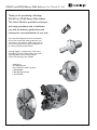
GD16C2 and GD3J2 Rotary Table Indexers User Manual B-126F
Setup and Operation
for the Hardinge®
GD16C2 and GD3J2
Rotary Table Indexers
Part No. BF -0009500-0126
Original U.S.A. Instructions
Hardinge Inc. One Hardinge Drive, Elmira, New York U.S.A. 14902-1507 800.843.8801 (Canada 800.468.5946) www.shophardinge.com
1
GD16C2 and GD3J2 Rotary Table Indexers User Manual B-126F
Thank you for purchasing a Hardinge
GD16C2 or GD3J2 Rotary Table Indexer.
This User’s Manual is provided to assist you
with setup procedures and to familiarize
you with the features, specifications and
maintenance recommendations of your unit.
The mechanical indexing head can be maintained by
the customer with proper cleaning, lubrication, and
maint-enance. Any necessary repairs required during
the warranty period will be made at Hardinge Inc. or
by a factory authorized representative.
Hardinge supplies a complete array of 16C and 3J
workholding products including collets, step chucks,
expanding collets, chucks and fixture plates.
Custom manufacturing is also available.
Hardinge Inc.
One Hardinge Drive
Elmira, New York 14902-1507 U.S.A.
p. 800.843.8801
p. 800.468.5946 (Canada)
f. 607.734.3886
Part No. BF -0009500-0126
2
Hardinge Inc. One Hardinge Drive, Elmira, New York U.S.A. 14902-1507 800.843.8801 (Canada 800.468.5946) www.shophardinge.com
GD16C2 and GD3J2 Rotary Table Indexers User Manual B-126F
Table of Contents
Important Safety Recommendations ………………………………………………………………………… 4
1. Introduction
1.1Description………………………………………………………………………………………
1.2 High Stiffness Overall System……………………………………………………………………
1.3 Machinable Part Size……………………………………………………………………………
1.4 Standard Spindle Clamp…………………………………………………………………………
1.5Features…………………………………………………………………………………………
1.6 Specifications and General Requirements………………………………………………………
1.7Dimensions………………………………………………………………………………………
7
7
7
7
9
10
11
2. Set Up
2.1
2.2
2.3
2.4
2.5
2.6
General Setup……………………………………………………………………………………
Use of Collets, Chucks and Face Plates…………………………………………………………
Use of the GD16C2 and GD3J2 Collet Closer…………………………………………………
Use of Collets with the Hardinge Collet Closer…………………………………………………
Removing the Hardinge Collet Closer…………………………………………………………
Tooling Locations…………………………………………………………………………………
13
15
15
16
17
19
3. Backlash Adjustment
3.1 Measuring Backlash……………………………………………………………………………… 20
3.2 Adjusting Backlash……………………………………………………………………………… 21
4. Routine Maintenance
22
22
23
23
23
Part No. BF -0009500-0126
4.1 Use of Oil- and Water-Soluble Coolants…………………………………………………………
4.2Lubrication………………………………………………………………………………………
4.3 Collet Key Replacement…………………………………………………………………………
4.4 Clean Up…………………………………………………………………………………………
5. Warranty……………………………………………………………………………………………………
Hardinge Inc. One Hardinge Drive, Elmira, New York U.S.A. 14902-1507 800.843.8801 (Canada 800.468.5946) www.shophardinge.com
3
GD16C2 and GD3J2 Rotary Table Indexers User Manual B-126F
Safety Recommendations
READ COMPLETE INSTRUCTIONS CAREFULLY BEFORE OPERATING THIS UNIT. Note: Equipment refers to
the rotary table indexer and/or machine it is used with.
When this instruction book was printed, the information given was current. However, since we are constantly improving
the design of our products, it is possible that the illustrations and descriptions may vary from the system you receive.
- WARNING Occupational Safety and Health Administration (OSHA) Hazard Communication Standard 1910.1200, effective May
25, 1986, and various state "employee right-to-know laws" require that information regarding chemicals used with this
equipment be supplied to you. Refer to the applicable section of the Material Safety Data Sheets supplied with your unit
when handling, storing, or disposing of chemicals.
HARDINGE SAFETY RECOMMENDATIONS
Your Hardinge machine is designed and built for maximum ease and safety of operation. However, some previously
accepted shop practices may not reflect current safety regulations and procedures and should be re-examined to insure
compliance with the current safety and health standards.
Hardinge Inc. recommends that all shop supervisors, maintenance personnel and machine tool operators be advised
of the importance of safe maintenance, setup and operation of Hardinge-built equipment. Our recommendations are
described below.
READ THESE SAFETY RECOMMENDATIONS BEFORE PROCEEDING ANY FURTHER.
READ THE APPROPRIATE MANUAL OR INSTRUCTIONS before attempting operation or maintenance of the
equipment. Make certain that you understand all instructions.
DO NOT ALLOW the operation or repair of equipment by untrained personnel.
CONSULT YOUR SUPERVISOR when in doubt as to the correct way to do a job.
WEAR SAFETY GLASSES AND PROPER FOOT PROTECTION at all times. When necessary, wear respirator, helmet,
gloves and ear muffs or plugs.
DON’T OPERATE EQUIPMENT unless proper maintenance has been regularly performed and the equipment is known
to be in good working order.
WARNING or INSTRUCTION TAGS are mounted on the unit for your safety and information. Do not remove them
or damage them.
DO NOT ALTER THE EQUIPMENT to bypass any interlock, overload, disconnect or other safety device.
DO NOT OPERATE EQUIPMENT if unusual or excessive heat, noise, smoke or vibration occurs. Report any excessive
or unusual vibration, sounds, smoke or heat as well as any damaged parts.
LIFTING AND HANDLING OF THE UNIT should be done with full knowledge of the unit weight and using proper
procedures.
MAKE CERTAIN that the equipment is properly grounded. Consult National Electric Code and all local codes.
REMOVE POWER FROM THE UNIT by unplugging the power cord before attempting repair or maintenance
(Where Applicable).
DON’T OPEN THE CONTROL BOX without consulting with Hardinge. (Where Applicable)
DON’T TOUCH ELECTRICAL EQUIPMENT when hands are wet or when standing on a wet surface.
ASCERTAIN AND CORRECT the cause of a shutdown caused by overload heaters before restarting the machine.
(Where Applicable)
KEEP THE AREA AROUND THE MACHINE well lit and dry.
KEEP CHEMICAL AND FLAMMABLE MATERIAL away from electrical or operating equipment.
4
Hardinge Inc. One Hardinge Drive, Elmira, New York U.S.A. 14902-1507 800.843.8801 (Canada 800.468.5946) www.shophardinge.com
Part No. BF -0009500-0126
REPLACE BLOWN FUSES with fuses of the same size and type as originally furnished. (Where Applicable)
GD16C2 and GD3J2 Rotary Table Indexers User Manual B-126F
Safety Recommendations (continued)
HAVE THE CORRECT TYPE OF FIRE EXTINGUISHER handy when machining combustible material and keep chips
clear of the work area.
DON’T USE a toxic or flammable substance as a solvent cleaner or coolant.
MAKE CERTAIN THAT PROPER GUARDING is in place and that all doors to the primary machine are closed
and secured.
DON’T OPEN GUARD DOORS of the primary machine while any machine component is in motion.
MAKE SURE chucks, closers, fixture plates and all other spindle-mounted workholding devices are properly mounted
and secured before starting the unit or the machine.
MAKE CERTAIN all tools are securely clamped in position before starting the unit or the machine.
REMOVE ANY LOOSE PARTS OR TOOLS left on the unit or the machine or in the work area before operating
the equipment. Always check the machine and work area for loose tools and parts especially after work has been
completed by maintenance personnel.
REMOVE CHUCK WRENCHES before starting the unit or the machine.
BEFORE PRESSING THE CYCLE START PUSH BUTTON, make certain that proper functions are programmed and that
all controls are set in the desired modes.
KNOW WHERE ALL STOP push buttons are located in case of an emergency.
CHECK THE LUBRICATION OIL LEVEL before operating the machine.
MAKE CERTAIN that all guards are in good condition and are functioning properly before operating the equipment.
INSPECT ALL SAFETY DEVICES AND GUARDS to make certain that they are in good condition and are functioning
properly before the cycle is started.
CHECK THE POSITION of any load/unload automation before pressing the CYCLE START push button.
CHECK SETUP, TOOLING, AND SECURITY OF THE WORKPIECE if the machine has been OFF for any length
of time.
DRY CYCLE a new setup to check for programming errors.
MAKE CERTAIN that you are clear of any "pinch point" created by moving slides before starting the machine.
DON’T OPERATE any equipment while any part of the body is in the proximity of a potentially hazardous area.
DON’T REMOVE CHIPS with hands. Use a hook or similar device and make certain that all machine movements
have ceased.
BE CAREFUL of sharp edges when handling a newly machined workpiece.
DON’T REMOVE OR LOAD a workpiece while any part of the equipment is in motion.
DON’T OPERATE ANY EQUIPMENT while wearing rings, watches, jewelry, loose clothing, neckties, or long hair
not contained by a net or shop cap.
DON’T ADJUST tooling or coolant hoses while the equipment is running.
DON’T LEAVE tools, workpieces or other loose items where they can come in contact with a moving component
of the equipment.
DON’T CHECK finishes or dimensions of workpiece near running spindle or moving slides.
DON’T ATTEMPT to brake or slow the equipment with hands or any makeshift device.
ANY ATTACHMENT, TOOL OR MACHINE MODIFICATION not obtained from Hardinge Inc. must be reviewed by
a qualified safety engineer before installation.
Hardinge Inc. One Hardinge Drive, Elmira, New York U.S.A. 14902-1507 800.843.8801 (Canada 800.468.5946) www.shophardinge.com
Part No. BF -0009500-0126
DON’T JOG SPINDLE in either direction when checking threads with a thread gage.
5
GD16C2 and GD3J2 Rotary Table Indexers User Manual B-126F
Safety Recommendations (continued)
USE CAUTION around exposed mechanisms and tooling especially when setting up. Be careful of sharp edges on tools.
DON’T USE worn or defective hand tools. Use the proper size and type for the job being performed.
USE ONLY a soft-faced hammer on tooling and fixtures.
DON’T USE worn or broken tooling on machine.
MAKE CERTAIN that all tool mounting surfaces are clean before mounting tools.
INSPECT ALL CHUCKING DEVICES daily to make certain that they are in good operating condition. Replace any
defective chuck before operating the machine.
USE MAXIMUM ALLOWABLE gripping pressure on the chuck. Consider weight, shape and balance of the workpiece.
DON’T EXCEED the rated capacity of the equipment.
DON’T LEAVE the equipment unattended while it is operating.
DON’T CLEAN the equipment with an air hose.
KEEP TOTE PANS a safe distance from the machine. Don’t overfill the tote pans.
DON’T LET STOCK project past the back end of the collet closer or equipment spindle without being adequately
covered and properly supported.
UNLESS OTHERWISE NOTED, all operating and maintenance procedures are to be performed by one person. To avoid
injury to yourself and others, be sure that all personnel are clear of the equipment when opening or closing the coolant
guard door and any access covers.
FOR YOUR PROTECTION - WORK SAFELY
DON’T OPERATE THE EQUIPMENT with damaged or worn electrical cables.
Part No. BF -0009500-0126
VERIFY that the electrical cables are not restrained or pinched during full travel movement of the machine.
6
Hardinge Inc. One Hardinge Drive, Elmira, New York U.S.A. 14902-1507 800.843.8801 (Canada 800.468.5946) www.shophardinge.com
GD16C2 and GD3J2 Rotary Table Indexers User Manual B-126F
1. Introduction
1.1 Description
The GD16C2 and GD3J2 Rotary Table Indexers are used for accurate and dependable positioning of medium parts in
machining operations such as milling, drilling, tapping, contouring and spiral milling.
The Hardinge® GD16C2 and GD3J2 Rotary Table Indexers are a fully integrable, programmable rotary positioning
device that saves on workspace without sacrificing performance. The mechanical indexing head holds the workpiece,
which is positioned by programming angular movements into the all-digital servo control as a slave to a CNC machine
or directly into a CNC control in a true 4th axis setup. The Hardinge All-Digital Servo Control is industry compatible
and will drive most brands of brush or brushless motor indexing heads. The mechanical indexing head features an
A2-5 spindle nose for spindle tooling compatibility with A2-5 spindle CNC lathes. The mechanical Indexing head is
configured to run in the horizontal position. If a vertical running position is required (spindle pointing up),
you must make alterations to the motor cover that are detailed as follows:
Located on the bottom of the motor cover when the indexer is in the horizontal position (spindle pointing
right or left), are two drain holes. If the indexer is to be mounted vertically, drill and tap these holes for
M5 set screws. Seal the holes using M5 set screws and thread sealant. Drill and tap a hole for a M5 set
screw on the side of the motor cover parallel with the back mounting face of the indexer. This will be
the new drain hole for the indexer when it is mounted vertically. If the indexer orientation is changed to
horizontal mounting, remove the two set screws and place one in the vertical mounting drain hole. If this
procedure is not followed, the warranty will be void for any contamination in the motor cover.
THE 16C/3J DUAL AND TRIPLE UNITS CAN BE RUN IN THE HORIZONTAL POSITION ONLY.
The GD16C2 and GD3J2 Rotary Table Indexer spindle is based on the industry standard A2-5 spindle design that has
been used in Hardinge lathe production for over a century. The Hardinge-engineered mechanical elements guarantee
the spindle will be accurate, repeatable, reliable and flexible to suit many different machining applications. The spindle
carries a centerline from the machine bed of 6.00"/152.4mm, which is compatible with many other indexing products.
The spindle is hardened and ground for accuracy and has a rigid design with dual angular contact bearings to support
heavy cutting forces. Positioning of the spindle is accomplished through a self-locking gear set.
1.2 High Stiffness Overall System
The Hardinge GD16C2 and GD3J2 Rotary Table Indexers uses a high-quality hardened gear system with a 60:1 ratio.
This type of gearing allows for an efficient forward driving capability (motor side through the worm) while at the same
time preventing back driving from occurring by the applied cutting forces at the spindle side. This is an important
operating characteristic of the high-ratio gear system since it adds stiffness into the machining operation. This spindle is
also equipped with a high-torque pneumatic fail-safe clamp which prevents chatter and adds a considerable amount of
stiffness. Stiffness or rigidity is one of the more important features of any system employed in the activity of machining
operations and is the driving force for Hardinge-engineered rotary systems.
1.3 Machinable Part Size
The Hardinge GD16C2 and GD3J2 Rotary Table Indexers have been designed for those parts that can be conveniently
clamped to the slotted face plate, or that fit into a 16C collet. Typical parts are in the range of approximately 5"/127mm
in diameter, and generally not longer than 7"/178mm without the use of a tailstock and are figured at a 50% duty cycle.
A typical cut is figured at 7.5 HP with face or end milling.
Part No. BF -0009500-0126
Larger part sizes than those described above can be handled with additional tailstock or trunnion support.
Hardinge Inc. One Hardinge Drive, Elmira, New York U.S.A. 14902-1507 800.843.8801 (Canada 800.468.5946) www.shophardinge.com
7
GD16C2 and GD3J2 Rotary Table Indexers User Manual B-126F
1.4 Standard Spindle Clamp
The Hardinge GD16C2 and GD3J2 Rotary Table Indexers come with a fail-safe spindle clamp that is standard right
from the factory. This clamp allows the spindle to handle cutting forces equal to 175 ft-lb/237 Nm allowing for greater
cutting forces in the non-contouring mode of operation. The unit contains a pressure sensor that will prevent indexing
in the event that air pressure drops below 85 psi to the clamp so that damage is prevented. Air is supplied to the clamp
via a quick-disconnect fitting on top of the motor cover. When equipped with the Hardinge servo control, the clamp
can be controlled automatically so that the clamp is engaged when the Rotary Table Indexer arrives at its programmed
destination or it can be controlled with "G" codes. For ease of use, a "C" will appear on the display of the control
whenever the clamp is engaged. There is a potential for a drop in air pressure if the air line supplying the Rotary Table
Indexer is also supplying something else with air. If you receive a low pressure alarm, the first thing you should check
is the air pressure supplied to the Rotary Table Indexer. Please note that even a momentary drop in air pressure can
create an alarm situation.
CAUTION: Never attempt to defeat the clamp protection logic as this may result in an opportunity for the system to
rotate when the clamp is engaged. This will cause an overload fault and repeated attempts to operate in this manner
may damage the clamp. The clamp requires a minimum of 85psi of dry filtered air to fully release the spindle and must
be supplied to the unit even if the clamp is not going to be used.
Quick-Disconnect Air Connection for Clamp function.
(Must supply 85 psi of dry filtered air at this location at all times before attempting to rotate unit)
(With Collet Closer)
(Without Collet Closer)
Part No. BF -0009500-0126
8
Hardinge Inc. One Hardinge Drive, Elmira, New York U.S.A. 14902-1507 800.843.8801 (Canada 800.468.5946) www.shophardinge.com
GD16C2 and GD3J2 Rotary Table Indexers User Manual B-126F
1.5 Features
RIGID DESIGN
Increased distance between large bearings support heavy cutting forces on large or small parts
HARDENED AND GROUND SPINDLE
For higher accuracy
DUAL ANGULAR CONTACT BEARINGS
Support heavy cutting forces
AUTOMATIC CIRCLE DIVISION (With Hardinge Servo Control)
You can program a step that automatically divides a circle into any number of equal parts between 2 and 999
STOP/FEED-HOLD (With Hardinge Servo Control)
You can use the STOP to feed-hold spindle movement without losing position on restart
FAST SETUPS (With Hardinge Servo Control)
All connectors are "quick-disconnect", ensuring fast and easy setups
INTERFACING (With Hardinge Servo Control)
Most CNC mills can be interfaced quickly and easily by using a spare "M" function which provides a switch-closer
as a signal between your mill and the control
LINEAR & SPIRAL MILLING (With Hardinge Servo Control)
For semi fourth-axis capability
MEMORY (With Hardinge Servo Control)
A nonvolatile memory retains your program even when power is turned OFF (–) and remembers the current spindle
position and step number
PROGRAM STORAGE (With Hardinge Servo Control) Store and recall up to fifty different programs
PROGRAMMABLE PARAMETERS (With Hardinge Servo Control)
You can alter many of the basic features by performing basic programming
PROGRAMMING (With Hardinge Servo Control)
Program to rotate the spindle clockwise or counterclockwise with step sizes from .001 to 9999.99 degrees. Using G83
& G84, continuous rotation is allowed. Contact Hardinge for maximum speeds based on duty cycle.
ABSOLUTE OR INCREMENTAL PROGRAMMING (With Hardinge Servo Control)
Up to 1000 different steps can be stored in memory and each step can be repeated (looped) 999 times
RS-232 INTERFACE (With Hardinge Servo Control)
For computer control of sending and receiving programs and controlling indexer via the CNC control of host machine
capable of RS-232 communication
RESOLUTION
Standard resolution of .001" degrees
SIMPLE EDITING (With Hardinge Servo Control)
Edit a program by simply writing over existing steps, or inserting or deleting a line (or several lines) between steps, with
automatic program line renumbering
SUBROUTINES (With Hardinge Servo Control)
Allows repeated sequences up to 999 times, saving programming time and memory space
VARIABLE FEED RATES
Variable from .001 deg./sec. to 300 deg./sec.
ONE-YEAR WARRANTY
The Hardinge GD16C2 and GD3J2 Rotary Table Indexers are provided with a one-year warranty against any defects in
material and workmanship.
Hardinge Inc. One Hardinge Drive, Elmira, New York U.S.A. 14902-1507 800.843.8801 (Canada 800.468.5946) www.shophardinge.com
Part No. BF -0009500-0126
ZERO RETURN (With Hardinge Servo Control)
An "automatic home" position can be programmed to return the spindle to its original starting position from any point
9
GD16C2 and GD3J2 Rotary Table Indexers User Manual B-126F
1.6 Specifications
Spindle:
Torque (ft-lb/Nm)
Runout Maximum (TIR)
Backlash (arc/sec)
Speed (degrees/sec)
RPM Maximum
Load Support
Spindle Nose
Spindle center-to-base (inch/mm)
Indexing:
Accuracy (arc/sec)
Repeatability (arc/sec)
Resolution (degree)
Max Rotation/Step (degree) Gear Diameter (inch/mm)
70 / 95
0.0002"
40
0.001 to 300
50
Dual Angular Contact Bearings
A2-5
6.000" / 152.4 ± 0.001 / .025
± 15
±5
0.001"
9999.99
6.2 / 157.0
Weight:
Rotary Table Indexer (lb/kg)
200 / 90.7
Workholding:
16C
3J
Collets-Round (maximum capacity) inch/mm
15/8" / 41.27
1¾" / 44.45
Collets-Hex (maximum capacity) inch/mm
113/32" / 35.71
117/32" / 38.89
9
Collets-Square (maximum capacity) inch/mm
1 /64" / 28.97
1-1/4" / 31.75
Step Chucks - Regular Depth (max. capacity)
up to 6" / 152.4
up to 6" / 152.4
Step Chucks - Extra-Depth (max. capacity)
up to 6" / 152.4
3-Jaw Chucks (diameter)
5, 6, 8 and 10"
6, 8 and 10"
1/2 - 4" / 12.70 - 101.60
1/2 - 4" / 12.70 - 101.60
Sure-Grip® Expanding Collets, Collet Style
1/2 - 4" / 3.17 - 101.60
Sure-Grip Expanding Collets, Spindle Style
Fixture Plate, Spindle Mount (diameter)
51/2" / 139.70, 87/8" / 225.42
5-1/2" / 139.70, 87/8" / 225.42
Fixture Plate, Collet Style (diameter)63/8" / 161.92
Slotted Face Plate (diameter)
10" / 254.00
10" / 254.00
Collet Stops (part-length control)
YES
YES
10
Notes: 1 - maximum torque applied before slipping occurs
Hardinge Inc. One Hardinge Drive, Elmira, New York U.S.A. 14902-1507 800.843.8801 (Canada 800.468.5946) www.shophardinge.com
Part No. BF -0009500-0126
Motor:
Type (hp/kW DC servo)
0.78 / 0.58 (with Hardinge Servo Control)
Clamping Torque 1
175 ft-lb / 237Nm
Gear Ratio (gear set)
60:1
Operating Specifications:
Duty Cycle
90% at full speed without tailstock
Operating Temperature / Humidity 41 to 104°F / 5 to 40°C, 85% Relative Humidity
Power Rating
120Vac, 60Hz, 15A or 230Vac, 50Hz, 10A
Oil Requirements
MOBILGEAR 600 XP 220
Air Pressure Range For Clamp (psi/bar)
85 - 94 / 5.9 - 6.5
GD16C2 and GD3J2 Rotary Table Indexers User Manual B-126F
1.7 Dimensions
GD16C2 and GD3J2 Indexer Single-Spindle Units for use with Hardinge Servo Control
11.49 (292)
12.12 (308)
6±.001
(152±.025)
15.70 (399)
9.48 (241)
4±.0003
(102±.008)
4.80 (122)
9.4 (239)
Front View
2 (51)
.74 (19)
4±.0003 (102±.008)
7.63 (194)
Side View
Bottom View
GD16C2 and GD3J2 Rotary Table Single-Spindle Units for use as 4th-Axis
11.49 (292)
12.12 (308)
6±.001
(152±.025)
9.48 (241)
9.4 (239)
Fanuc 17.50 (445)
Siemens/Heidenhain/Okuma 20.05 (509)
Front View
.74 (19)
2 (51)
4±.0003 (102±.008)
7.63 (194)
Side View
Bottom View
Hardinge Inc. One Hardinge Drive, Elmira, New York U.S.A. 14902-1507 800.843.8801 (Canada 800.468.5946) www.shophardinge.com
Part No. BF -0009500-0126
4±.0003
(102±.008)
4.80 (122)
11
GD16C2 and GD3J2 Rotary Table Indexers User Manual B-126F
GD16C2-02, -03 and GD3J2-02, -03 Indexer Multiple-Spindle Units for use with Hardinge Servo Control
Front View
13.62
(346)
7.87±.01
(200±.25)
1 (25.4)
10±.01
(254±.25)
10±.01
(254±.25)
1.89 (48)
39.09 (993) Triple; 29.09 (739) Dual
Bottom View
11.57
(294)
.53 (13.49)
9.52
(242)
31.93 (811) Triple; 20.98 (533) Dual
THE 16C/3J DUAL
AND TRIPLE UNITS
CAN BE RUN IN
THE HORIZONTAL
POSITION ONLY.
33.89 (861) Triple; 23.77 (604) Dual
GD16C2-02, -03 and GD3J2-02, -03 Rotary Table Multiple-Spindle Units for use as 4th Axis
Front View
13.62
(346)
7.87±.01
(200±.25)
1 (25.4)
10±.01
(254±.25)
10±.01
(254±.25)
1.89 (48)
Dual Unit Fanuc 30.89 (785)
Dual Unit Siemens/Heidenhain/Okuma 33.44 (849)
Triple Unit Fanuc 40.89 (1039)
Triple Unit Siemens/Heidenhain/Okuma 43.44 (1103)
Bottom View
11.57
(294)
.53 (13.49)
9.52
(242)
12
Hardinge Inc. One Hardinge Drive, Elmira, New York U.S.A. 14902-1507 800.843.8801 (Canada 800.468.5946) www.shophardinge.com
Part No. BF -0009500-0126
31.93 (811) Triple; 20.98 (533) Dual
33.89 (861) Triple; 23.77 (604) Dual
GD16C2 and GD3J2 Rotary Table Indexers User Manual B-126F
The GD16C2 and GD3J2 Rotary Table Indexer systems can be ordered with the motor on either side of the unit. If
the unit is ordered with the motor in the standard orientation (motor on the left looking at the spindle face) counterclockwise is the positive direction and the spindle key will be in the 12 o’clock position when the rotary is in the zero
position. If the unit is ordered with the motor on the right hand side of the unit, then the spindle will move clockwise
when programmed to move in the positive direction and the spindle key will be in the 6 o’clock position when the
rotary is in the zero position.
NOTE: The Hardinge servo control and most machine control parameters can be changed to make either clockwise
or counter-clockwise the positive direction.
2. Set Up
2.1 General Setup
1. Fill out the warranty information by visiting www.hardinge.com/rotarywarranty on the internet.
2. Place the Rotary Table Indexer on the machine. Route the cable from the head so that it avoids tool changers
and table edges. Cable slack must be provided for your machine’s movements. If the cable is cut the motor will
fail prematurely. Replace a damaged cable immediately. Secure the Rotary Table Indexer to the machine’s T-slot
table as shown below (upright or on its back). Mounting unit on its back will require a special mounting plate.
T-nut packages are available for purchase for various T-slot tables. Kit includes (2) T-nuts, (2) bolts, and (2) flat
washers. Check to verify that all clearances are satisfied in full machine axis' movements and that there is no
possibility of a collision.
M10 Eyehooks supplied for lifting. Reposition eyehooks to the face for lifting and mounting
the Rotary Table Indexer on its back. Remove eyehooks
before operating the unit.
Located on the bottom of the motor cover when the indexer is in the
horizontal position (spindle pointing right or left), are two drain holes.
If the indexer is to be mounted vertically, drill and tap these holes for
M5 set screws. Seal the holes using M5 set screws and thread sealant.
Drill and tap a hole for a M5 set screw on the side of the motor cover
parallel with the back mounting face of the indexer. This will be the
new drain hole for the indexer when it is mounted vertically. If the
indexer orientation is changed to horizontal mounting, remove the
two set screws and place one in the vertical mounting drain hole. If
this procedure is not followed, the warranty will be void for any
contamination in the motor cover.
Hardinge Inc. One Hardinge Drive, Elmira, New York U.S.A. 14902-1507 800.843.8801 (Canada 800.468.5946) www.shophardinge.com
Part No. BF -0009500-0126
The mechanical Indexing head is configured to run in the horizontal
position. If a vertical running position is required (spindle pointing
up), you must make alterations to the motor cover that are detailed
as follows:
13
GD16C2 and GD3J2 Rotary Table Indexers User Manual B-126F
3. Place the Rotary Table Indexer in an area free from chips and coolant where air can circulate freely.
Do not let chips pile up over the motor enclosure, as this would prevent proper cooling.
4. Connect the GD16C2 or GD3J2 Rotary Table Indexer using one of the techniques as described in the
Hardinge servo control or Hardinge 4th-axis manual, which will be included with the mechanical unit.
5. Route the cable over the back of the mill sheet metal (if using Hardinge Servo Control).
6. If adding an indexer to a Hardinge mill using a remote CNC cable or as a true 4th axis, refer to the
instructions in the Hardinge 4th-axis manual or call the Hardinge service department.
7. If using the Hardinge servo control, secure it in required placement. Do not cover any surface of the control, as it
will quickly overheat. Do not place the unit on top of other hot electronic controls.
7a. Connect the two cables from the indexer to the controller in the appropriate locations.
CAUTION: Never connect or disconnect these cables with the power on. Instant failure will result.
7b. Connect the AC line cord to a 120V AC grounded receptacle. The cord is a three-wire ground type and the ground must be connected. Power is 120VAC. The power service must supply a minimum of 15 amps
continuously. Conduit wire must be 12 gauge or larger and fused for at least 20 amps. If an extension cord
is to be used, use a three-wire ground type and the ground line must be connected. Avoid outlets that
have large electric motors connected to them. Use only heavy-duty 12-gauge extension cords capable of
20 amp load. Do not exceed a length of 30 feet. Permanent installations should be hard-wired or installed
with locking plugs.
7c. Semi-Fourth Axis: Connect the remote interface cable. See separate Hardinge Servo Control manual.
8. Connect 85 psi of dry filtered air to the quick-disconnect fitting on top of the indexer if using a collet closer
or on top of the motor cover if not using a collet closer for releasing the spindle clamp. Refer to section 1.4.
CAUTION: Never index the Rotary Table Indexer without 85 psi of dry filtered air connected to the fitting,
or mechanical damage will occur.
9. Check the oil level. If it is low, add oil. Use MOBILGEAR 600 XP 220 only.
10. Save the packing materials in case you need to ship the unit.
11. At the end of the workday or shift it is important to clean the Rotary Table Indexer. The Rotary Table Indexer
should be free of any chips or grime. Clean with a chip brush and apply a coat of rust preventative.
CAUTION! Do not use an air gun around the front or rear seals. Chips may damage the seal if blown in
with an air gun.
NOTE: Prior to powering on the control, read and understand the entire control or 4th axis manual.
12. Turn on the mill (and servo control, if applicable) and home the indexer by pressing the zero return button.
The Rotary Table Indexer homes in the counter-clockwise direction as viewed from the spindle.
14
Hardinge Inc. One Hardinge Drive, Elmira, New York U.S.A. 14902-1507 800.843.8801 (Canada 800.468.5946) www.shophardinge.com
Part No. BF -0009500-0126
NOTE: If using a tailstock, always use Live Centers. The use of Dead Centers could cause damage to the
gear system.
GD16C2 and GD3J2 Rotary Table Indexers User Manual B-126F
2.2 Use of Collets, Sure-Grip® Expanding Collets, Sure Grip® 3-Jaw Power Chucks and Face Plates
The unit accepts standard Hardinge 16C or 3J collets, step chucks, ID gripping collets, chucks and face plates. When
inserting the collet, align the keyway on the collet with the key inside the spindle. Push the collet in and turn the collet
closer drawbar clockwise until proper collet tightness is obtained. See Section 2.4.
Chucks and face plates utilize the A2-5 spindle nose on the indexer. Always make sure that the spindle and chuck or
face plate are free of dirt and chips. Align the chuck draw tube keyway with the spindle collet key and slide the chuck
onto the spindle. Turn the collet closer drawtube to engage the chuck. Push the chuck tight to the spindle and tighten
the chuck mounting bolts to the proper torque indicated in your chuck installation manual. Use the collet closer
drawtube to adjust the chuck for proper stroke required for ID and OD gripping. Since the A2-5 spindle nose is such
a tight tapered fit, a face plate or 3-jaw chuck may be difficult to remove from the spindle even after the bolts are
removed. If this happens, support the face plate or 3-jaw chuck with a hoist and lightly strike the outside diameter of
the face plate or 3-jaw chuck with a piece of brass, a plastic hammer, or a rubber hammer so that nothing is damaged.
NOTE: A hoist may be required to mount a 3-jaw chuck depending on the size of the chuck.
2.3 Use of the Collet Closer
The collet closer has a 1.634" (41.5mm) through-hole design with pneumatic open and close. The through-hole can be
used for through-spindle coolant or for holding long parts. The pneumatic closer has .625" (15.87mm) of stroke which
allows the use of power chucks. The air pressure can be adjusted to achieve different drawbar forces out of the collet
closer as shown in the chart below.
CAUTION: If it is desired to use less than 85 psi of dry filtered air on the collet closer, the spindle clamp must be
plumbed separately from the collet closer.
NOTE: Do not supply the collet closer with air pressure in excess of 120 psi at any time.
Air Pressure
Drawbar Force
(psi)
(lbs)
10
399
20
798
30
1197
40
1595
50
1994
60
2393
70
2792
80
3191
85
3390
90
3590
100
3989
110
4387
120
4786
Hardinge Inc. One Hardinge Drive, Elmira, New York U.S.A. 14902-1507 800.843.8801 (Canada 800.468.5946) www.shophardinge.com
Part No. BF -0009500-0126
16C Collet Closer Force Chart
15
GD16C2 and GD3J2 Rotary Table Indexers User Manual B-126F
2.4 Use of Collets with the Hardinge Collet Closer
NOTE: All collets must be free from burrs and in good condition.
To install a collet, first make sure that the closer is in the open position. Loosen the (4) M6 bolts that hold the
drawtube to the closer piston until they are fully disengaged from the piston. The bolts will not come all of the way out
of the drawtube due to snap rings in the counterbored holes. Align the collet keyway with the spindle key and insert
the collet and turn the draw tube to engage the collet. Turn the drawtube until the collet grips the part and then back
off approximately ¼ turn. This will be a good starting point for fine-tuning the grip range. Turn the drawtube until the
bolts in the drawtube align with the holes in the piston and torque bolts to 10 ft-lbs.
NOTE: To prevent excessive wear and collet sticking, make sure collets are in good condition and free from burrs.
A light coat of Molybdenum grease on the collet wear surfaces will extend the life of the spindle and/or collet and help
prevent sticking, especially when operating dry.
Part No. BF -0009500-0126
LOOSEN
16
Hardinge Inc. One Hardinge Drive, Elmira, New York U.S.A. 14902-1507 800.843.8801 (Canada 800.468.5946) www.shophardinge.com
GD16C2 and GD3J2 Rotary Table Indexers User Manual B-126F
2.5 Removing the Hardinge Collet Closer
Part No. BF -0009500-0126
Air collet closers fitted at the factory are not intended to be removed. However, if servicing is required, remove air
supply and all workholding and then disconnect the air lines from the collet closer. Remove the (4) M6 bolts that hold
the anti-rotation bracket to the housing and remove bracket. Remove the (10) M6 bolts near the outer edge of the
collet closer body. The collet closer should now be free to remove from the rotary table indexer. If access to the
spindle clamp is required, remove the (6) M6 bolts that hold the collet closer adapter plate to the spindle of the indexer
followed by the (4) M5 bolts that hold the clamp cover in place. You should now be able to see the spindle clamp.
Hardinge Inc. One Hardinge Drive, Elmira, New York U.S.A. 14902-1507 800.843.8801 (Canada 800.468.5946) www.shophardinge.com
17
CAUTION! The Hardinge Collet Closer relies on air pressure to maintain clamping force and is released upon the
removal of the air pressure. For situations where the air is accidentally removed during operation, a check valve will
temporarily maintain clamping force so that the system can be brought to a safe STOP condition.
18
Hardinge Inc. One Hardinge Drive, Elmira, New York U.S.A. 14902-1507 800.843.8801 (Canada 800.468.5946) www.shophardinge.com
Part No. BF -0009500-0126
GD16C2 and GD3J2 Rotary Table Indexers User Manual B-126F
6±.001
(152±.025)
GD16C2 and GD3J2 Rotary Table Indexers User Manual B-126F
9.48 (241)
4.80 (122)
9.4
15.70 (399)
2.6 Tooling Locations
The Rotary Table Indexer system is equipped with
tooling points in order to speed setups. One of the
most time-consuming procedures in setup is aligning
the head with the table. On the mounting surfaces
there are two 0.500" (12.7mm) bored holes on 4.000"
(101.6mm) centers. The holes on the bottom surface
are parallel to the spindle within 0.001" (0.025mm) per
6 inches (152.4mm) and on the center within ±0.001"
(0.025mm).
.74 (19)
7.63 (194)
2 (51)
4±.0003 (102±.008)
By boring machine holes in your tooling plate, setups become routine. Using the tooling holes will also prevent the
head from shifting on the mill table when the part is subjected to heavy cutting forces. On CNC mills a machined
stepped plug of 0.500" (12.7mm) diameter on one side and 0.625" (15.87mm) on the other comes with the Hardinge
head. The 0.625" (15.87mm) diameter fits into the T-slot of the mill table. This will give quick parallel alignment that
will be close enough for most jobs.
Part No. BF -0009500-0126
NOTE: 0.625" (15.87mm) and 18mm plugs are supplied as standard. Plugs can be turned down to another diameter to
accommodate tables with different slot dimensions.
Hardinge Inc. One Hardinge Drive, Elmira, New York U.S.A. 14902-1507 800.843.8801 (Canada 800.468.5946) www.shophardinge.com
19
GD16C2 and GD3J2 Rotary Table Indexers User Manual B-126F
3. Backlash Adjustment
3.1 Measuring Backlash
Make sure the spindle clamp is released prior to attempting to
measure backlash. To measure backlash, you need the use of
a .0001" indicator and a magnetic V-block or magnetic block.
Home the indexer as that is where backlash is checked at the
Hardinge Factory. Place the magnetic block on the indexer
spindle face so that the top of the block is parallel to the
machine bed and in line with the spindle centerline as shown in
the picture. Set up the indicator so that it is measuring the top
of the magnetic block 2 inches from the center of the spindle.
Use a wrench or steel bar to move the spindle by placing it
across (2) two M10 bolts that need to be screwed into the face
of the spindle.
Use your hand to put pressure on the wrench or bar to physically move the spindle in one direction. Move the spindle
in that one direction until you measure approximately 0.001" on your indicator. Remove your hand from the wrench
or bar so that the spindle can spring back to a nominal position. When the indicator shows that the spindle has
sprung back some, zero out the indicator at this position. Put pressure on the wrench or bar to move the spindle in
the opposite direction now. Again, you are going to want to move the spindle at least 0.001" and release the wrench
or bar so the spindle can spring back. Record the reading on your indicator as this will be used to calculate gear
backlash. Take the distance recorded by the indicator and divide that number by 2 because your measurement was
taken 2 inches from spindle centerline. Now take the inverse tangent (tan)-1 of this calculated number and that will
be how many degrees of backlash you have in your gears. To figure out how many arcseconds that is, simply multiply
the degrees you calculated by 3600. If you calculate your backlash to be 40 arcseconds or less, then no backlash
adjustments are necessary. To compensate for the mechanical backlash electronically, see the control manual. A chart
of various angles in arcseconds measured linearly at different radii along with a pictorial description of backlash follows.
2" radius
3" radius
4" radius
5" radius
6" radius
1 arc-sec
0.0000048"
0.0000097"
0.000014"
0.000019"
0.000024"
0.000029"
5 arc-sec
0.000024"
0.000048"
0.000073"
0.000097"
0.00012"
0.00014"
10 arc-sec
0.000048"
0.000097"
0.00014"
0.00019"
0.00024"
0.00029"
20 arc-sec
0.000096"
0.00019"
0.00029"
0.00039"
0.00048"
0.00058"
30 arc-sec
0.00014"
0.00029"
0.00044"
0.00058"
0.00073"
0.00087"
40 arc-sec
0.00019"
0.00038"
0.00058"
0.00077"
0.00097"
0.0012"
Part No. BF -0009500-0126
1" radius
20
Hardinge Inc. One Hardinge Drive, Elmira, New York U.S.A. 14902-1507 800.843.8801 (Canada 800.468.5946) www.shophardinge.com
GD16C2 and GD3J2 Rotary Table Indexers User Manual B-126F
3.2 Adjusting Backlash
NOTE: A small amount of backlash is required for the gear set.
If it is determined that the backlash needs to be reduced, Hardinge highly recommends that the unit be sent back to the
factory if still within the warranty period. If the customer decides to make the adjustments on their own, Hardinge has
included the following detailed instructions.
2.5625
(65.1)
2.125
(54)
1. A special tool is required to move the
eccentric to adjust the backlash. This tool
can be made from either steel or aluminum.
Failure to make and use this tool may result
in damage to the eccentric which will NOT
be covered under warranty.
1.1875
(30.2)
2.375
(60.3)
PRESS FIT
(2) PINS
1
/4" x 1" LONG
0.375
(9.5)
SLIDING
FIT
0.5625
(14.3)
2.875
(73.0)
1.0
(25.4)
8.0
(203.2)
0.5625
(14.3)
DRILL 9/16" x 11/16" DEEP
2. The eccentric that you will be adjusting is
on the side of the indexer opposite of the
motor cover. Start by removing the (4) four
M6 bolts that hold the square black plate to
that side of the indexer housing.
3. Remove the (4) four M6 bolts in the
eccentric housing.
REMOVE
(4) BOLTS
ROTATE
DIMPLE
Hardinge Inc. One Hardinge Drive, Elmira, New York U.S.A. 14902-1507 800.843.8801 (Canada 800.468.5946) www.shophardinge.com
Part No. BF -0009500-0126
4. Take note of the small dimple in the face of
the eccentric. The eccentricity of the
eccentric goes towards this dimple. Use the
special tool you made to turn the eccentric
to the next available hole in the direction
that makes the dimple go towards the top
of the indexer housing. This may be either a
clockwise or counter-clockwise rotation.
5. Replace the (4) four M6 bolts in the
eccentric and measure the backlash again.
21
GD16C2 and GD3J2 Rotary Table Indexers User Manual B-126F
6. Continue adjusting the eccentric one hole at a time and checking backlash until an acceptable backlash
is achieved.
NOTE: Make sure when adjusting backlash that you have at least 10 arcseconds of backlash in the gear set
or the gears may prematurely wear.
7. Put the black plate back on the indexer once finished adjusting backlash.
4. Routine Maintenance
4.1 Use of Oil- and Water-Soluble Coolants
For the use of oil- and water-soluble coolants, the following guidelines should be observed:
•
DO NOT SUBMERGE THE UNIT IN COOLANTS. Keep the coolant lines on the workpiece spraying
away from the head. Tool spraying and splatter usually will not be detrimental to the motor, however, large
amounts of pressurized coolant should be directed away from the head. Some machining centers provide
flood coolant at enormous rates so that the head is practically submerged. Try to cut the flow down to
match the job.
•
Inspect the cables and gaskets for cuts or swelling. Damage must be repaired immediately.
4.2Lubrication
To check the lube level of the Hardinge Rotary Table Indexer, view the level of lube visible in the lubricant window when
the unit is stopped. The window is located on the front and side of the unit opposite the motor. The lube level should
reach the middle of the window. If necessary, add lubricant until the level reaches the midpoint of the window.
Part No. BF -0009500-0126
To add lubricant to the unit, locate and remove the pipe-plug from the lube fill port. This is located behind the eyehook
on top of the unit. Add MOBILGEAR 600 XP 220 until the proper level is reached. Replace the fill port pipe-plug and
tighten. Replace the oil every two years.
22
Hardinge Inc. One Hardinge Drive, Elmira, New York U.S.A. 14902-1507 800.843.8801 (Canada 800.468.5946) www.shophardinge.com
GD16C2 and GD3J2 Rotary Table Indexers User Manual B-126F
Drain oil using the drain location found on the front or bottom of the rotary table indexer.
4.3 Collet Key Replacement
Remove the set screw in the collet key access hole and then remove the collet key using a 3mm Allen wrench for both
items. Screw the new collet key into the spindle until it begins to protrude into the inside diameter of the spindle. Align
the flat on the key to be parallel with the spindle centerline. Slide a collet into the spindle to check the key fit. Remove
collet and adjust key until proper fit is achieved. Loctite #242 can be used to secure the key. Replace the set screw
back into the key access hole using pipe sealant.
4.4 Clean Up
5. One-Year Limited Warranty
The Hardinge GD16C2 and GD3J2 Rotary Table Indexer Systems are provided with a One-Year Warranty against
any defects in material and workmanship. Specific details of the warranty can be found in the Hardinge Terms and
Conditions document associated with the purchase agreement.
Hardinge Inc. One Hardinge Drive, Elmira, New York U.S.A. 14902-1507 800.843.8801 (Canada 800.468.5946) www.shophardinge.com
Part No. BF -0009500-0126
At the end of the workday or shift it is important to clean the Rotary Table Indexer. The head should be free of any
chips or grime. Clean with a chip brush and apply a coat of rust preventative. Do not use an air gun around front or
rear seals. Chips may damage seal if blown in with an air gun.
23
Hardinge Inc. | One Hardinge Drive | P.O. Box 1507 | Elmira, New York 14902-1507 USA
USA: 800.843.8801 | Canada: 800.468.5946 | Fax: 607.734.3886
To Order Online: www.shophardinge.com | Corporate Home Page: www.hardinge.com | E-mail: [email protected]
All specifications subject to change without notice. All marks indicated by ® or ™ are trademarks of Hardinge Inc. Instruction Manual B-126F • Litho in U.S.A. • © Hardinge Inc. 2013