1
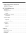
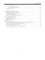
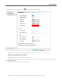
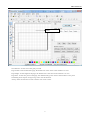
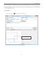
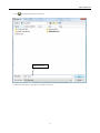
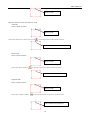
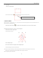
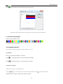
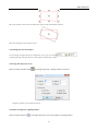
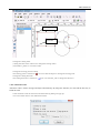
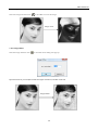
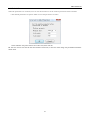
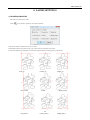
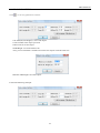
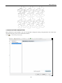
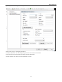
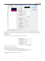
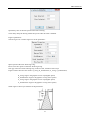
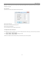
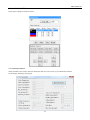
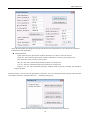
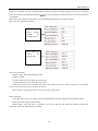
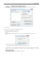
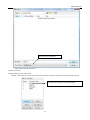
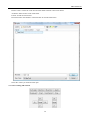
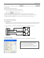
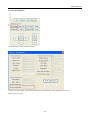
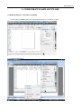
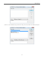
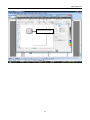
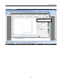
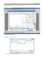
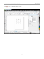
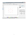
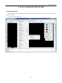
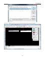
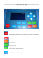
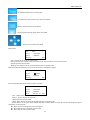
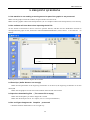
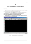
PHCAD3.3
rev 7-23-2011
USER’S MANUAL
The operation mode and settings may differ due to upgrades of software.
Any differences are subject to the software
PHCADManual
1.INTRODUCTION ...................................................................................................................................................3
1.1 INTRODUCTION OF LASER ENGRAVING AND CUTTING SYSTEM ...............................................3
1.2 DIFFERENT VERSIONS OF SOFTWARE................................................................................................3
1.3 SUPPORTED FORMATS............................................................................................................................3
1.4 ENVIRONMENTAL REQUIREMENTS ....................................................................................................3
2. INSTALLATION OF SOFTWARE.......................................................................................................................4
2.1 INSTALLING PROCEDURE......................................................................................................................4
3. BASIC SETTINGS OF INDEPENDENT SOFTWARE .......................................................................................5
3.1 MAIN INTERFACE.....................................................................................................................................5
3.2 SETTING OF THE WORK AREA..............................................................................................................6
3.3 OPEN AND SAVE THE FILE.....................................................................................................................8
3.3.1 open the file .......................................................................................................................................8
3.3.2 save the file ........................................................................................................................................9
3.4 IMPORT AND EXPORT FILE..................................................................................................................10
3.4.1 import file ........................................................................................................................................10
3.4.2 Export of the file..............................................................................................................................12
3.5 DRAW SIMPLE GRAPHICS AND EDIT NODE ....................................................................................12
3.5.1 Draw simple graphics ......................................................................................................................12
3.5.2 edit node ..........................................................................................................................................13
3.6 SELECT OBJECT ......................................................................................................................................15
3.7 COLOR OF AN OBJECT ..........................................................................................................................16
3.8 CHANGE AN OBJECT .............................................................................................................................16
3.8.1 Mirror...............................................................................................................................................16
3.8.2 rotate an object.................................................................................................................................16
3.8.3 change the size of an object .............................................................................................................17
3.8.4 Copy the objects by array ................................................................................................................17
3.8.5 move an object to original position..................................................................................................17
3.9 ALIGN OBJECTS ......................................................................................................................................18
3.10 GROUP OBJECTS...................................................................................................................................18
3.11 ZOOM THE VIEW ..................................................................................................................................18
3.12 IMPORTANT TOOLS .............................................................................................................................18
3.12.1 Manual order..................................................................................................................................18
3.12.2 Automatic order .............................................................................................................................19
3.12.3 Image invert ...................................................................................................................................20
3.12.4 Image Dither ..................................................................................................................................20
3.13 Default Parameters....................................................................................................................................21
4. LASER SETTINGS..............................................................................................................................................22
4.1 POSITION RELATIVE..............................................................................................................................22
4.2 ARRAY PARAMETERS ...........................................................................................................................23
4.3 MANUFACTURER PARAMETERS........................................................................................................24
4.4 WORK PARAMETER...............................................................................................................................27
4.5 COM ...........................................................................................................................................................28
4.6 LAYER OPTIONS .....................................................................................................................................29
4.6.1 Layer parameters .............................................................................................................................29
4.6.2 adjust the orders of the layers ..........................................................................................................32
1
PHCADManual
4.7 MACHINE CONTROL..............................................................................................................................33
4.7.1 control parameters ...........................................................................................................................33
4.7.2 download data and machine control ................................................................................................36
4.7.3 start working and controls................................................................................................................38
4.8 Auto Focus Setup………………………………………………………………………………………….40
4.8.1
5. CORELDRAW BASED SOFTWARE ................................................................................................................41
5.1 Add PH_lasercut tool bar to coreldraw.......................................................................................................41
5.2 show the hidden PH_LaserCut toolbar .......................................................................................................45
5.3 IMPORT DST/DSB FILE ..........................................................................................................................45
5.4 SWITCH TO INDEPENDENT SOFTWARE............................................................................................46
6. AUTOCAD BASED SOFTWARE ......................................................................................................................48
6.1 ADD PHcad toolbar....................................................................................................................................48
6.2 Switch AutoCAD to PHcad: .......................................................................................................................50
7. CONTROL PANEL .............................................................................................................................................52
8. FREQUENT QUESTIONS ..................................................................................................................................56
8.1 the machine is not working or moving around or part of the graphs is not processed................................56
8.2 the software will shut down when importing the dxf file ...........................................................................56
8.3 Panel tips ( buffer distance not enough) .....................................................................................................56
8.4 tips when downloading files ( The current file is empty) ........................................................................56
8.5 the real figure Imagines the Graphics processed ..................................................................................56
2
PHCADManual
1.INTRODUCTION
1.1 INTRODUCTION OF LASER ENGRAVING AND CUTTING SYSTEM
The laser control system is computer based including user friendly software that works well in conjunction with
CorelDraw and AutoCad. User will learn how to use the software to control the machine in this manual.
1.2 DIFFERENT VERSIONS OF SOFTWARE
There are three versions of software: Standalone, CorelDraw x12 or higher, and AutoCAD 2004 or higher version
1.3 SUPPORTED FORMATS
Vector format: dxf, ai, plt, dst, dsb etc.
Bitmap format: bmp,jpg,gif,png,mng etc.
1.4 ENVIRONMENTAL REQUIREMENTS
1. Above PIII or PV recommended
2. Memory, above 1G recommended
3. Windows2000/XP/VISTA, XP recommended
4. Support the software of CoreDraw11 and CorelDraw12,CorelDrawX3,CorelDrawX4 and AutoCad
3
PHCADManual
2. INSTALLATION OF SOFTWARE
2.1 INSTALLING PROCEDURE
(1) Double click “Setup.exe” in the installation directory, the following dialog will pop up.
(2) Click “Driver_install” to install USB driver. The following dialog will pop up when USB driver is
successfully installed.
(3) Choose version of software and the language you need. please refer to the following picture:
Choose edition
Choose language
(4) Click “Install”to install laser software. The following dialog will pop up when software is successfully
installed.
4
PHCADManual
3. BASIC SETTINGS OF INDEPENDENT SOFTWARE
3.1 MAIN INTERFACE
The main interface will be as following after starting the software. Learn the basic settings of the software is an
requirement of starting your work.
Menu Bar
Tool Bar
Object Bar
Edit Bar
Control Panel
Align Bar
Color Bar
Status Bar
MENU bar: the major functions of the software will be achieved by the following orders:
FILE, EDIT, DRAW, TOOL, OPTIONS, VIEW, AND HELP.
Tool bar: these most useful tools are selected from the menu bar.
Object bar: change the settings of the selected object.
Edit bar: on the left side of the work area. some of the most useful editing tools are put here to make
operating easier.
Align bar: to align multiple objects to make typeset easier.
Color bar: change the color of the selected objects.
Control panel: by using control panel, you can finish lots of complicated tasks, including settings
communication port, settings of layer parameters, loading of graphs etc.
5
PHCADManual
3.2 SETTING OF THE WORK AREA
Click option/system system option or click
,the following dialog will pop up
Nudge offset:moving distance of the selected object when press arrow“←”,“→”,“↑”,“↓”
Paste offset:shift distance of the pasted object.
Language: choose the language you prefer.
Speed unit: set the velocity unit used in the software.
Machine Zero: the zero point of the machine(limit point) must be correct, or the finished picture might be
converse(pay attention)
Selected color:boder color of the selected object.
Show grid:select “show grid”,the work area will be filled with grid as showed below:
6
PHCADManual
Grid
Grid distance: set the size of the grid you need.
Page width: set the width of the page, the default size is the same as the machine’s X-axis
Page height: set the height of the page, the default size is the same as the machine’s Y-axis
Page Zero: set the zero point of the page, the default setting is the same as the machine’s zero point.
Simulating show objects of engraving: tick to use the function.
Always show the welcome screen at launch: tick to let it show.
7
PHCADManual
3.3 OPEN AND SAVE THE FILE
The files will be saved in pwj format the whole project will be saved safely in pwj format,this means all the
information, including parameters of the layers and orders. To save the imported files as pwj format will make
your future work a piece of cake.
3.3.1 open the file
(1)click File/Open or click
, the following dialog will pop up:
Preview current image
(2)select the file you want to open(ex:111.pwj)and click open.
8
PHCADManual
3.3.2 save the file
(1)click
, the following dialog will pop up:
Input file name
(2) Enter the file name in the edit box and then click save.
9
PHCADManual
3.4 IMPORT AND EXPORT FILE
The software use pwj format to save files, therefore when you need to use other formats, you have to use
import function. The supported formats are: dxf, ai, plt, dst, dsb etc.
And you can also export files as plt format.
3.4.1 import file
Click File/import or click
,the following dialog will pop up. Select the object and click open.
Tick Unite lines, when importing graphs, the software will combine the adjacent lines as one. You can
click
to set Unite tolerance as the following picture:
10
PHCADManual
Unite tolerance: when the distance between adjacent lines is less than the combination tolerance,the lines will be
combined as one.
Tick DST auto smooth: when importing DST/DSB formats, the graphic data will be optimize (smooth the graphs
to make the laser work more smooth)
Smooth: set the smoothness of the graphs, the smoother the graph is, and the more anamorphic it will be.
Tick auto order, arrange graphs orderly when importing files(thus the laser will work orderly).click
to set
the rules of arrangement as the following picture.
Tick Order by layer, layers of the same color will be executed in sequence (the machine will first laser layer of the
same color and then laser another color)
Tick Inner to outer, the machine will cut from Inner to outer.
Tick automation set cut directions, the machine will set the starting points and directions for the target graphs
automatically.
Tick path run region, the graphs will be arranged by the set directions. This function is usually used to arrange
11
PHCADManual
graphics array (circular array, rectangular array).
PLT Unit, length unit, the size of the imported graphs will be differ according to the setting of the PLT unit.
Tick reserve the current document data, when you import another file, the former file will be reserved.
Tick preview, preview the file you select.
3.4.2 Export of the file
to save the files in PLT format.
Click File/export or click
3.5 DRAW SIMPLE GRAPHICS AND EDIT NODE
3.5.1 Draw simple graphics
Draw a line
Click menu or click
in the edit tool bar, now you can draw lines in the work Area. If you press “ctrl”, you
can draw straight line.
Draw polyline
Click polyline in draw menu or
in edit tool bar to draw polyline.
Draw Bezier
Click Bezier in draw menu or
in edit tool bar to draw bezier.
Draw Rectangle
Click Rectangle in draw menu or
in edit tool bar to draw Rectangle. Press “Ctrl”to draw square.
Draw Ellipse
Click ellipse in draw menu or
in edit tool bar to draw ellipse. Press “Ctrl” to draw circle.
Edit text
Click text in draw menu or
in edit tool bar, and then double left click the mouse, the following dialog will
pop up
12
PHCADManual
Choose font and choose the size of the character and then input the text the click ok.
3.5.2 edit node
Click edit node in draw menu or click
, these buttons
(add node)
(delete node)
(connect node)
(separate node) in the edit object bar will be activated.
Select object
Click object to select it. The " " is the node of the selected object.A selected rectangle is as below:
Point in the selected object
Click the line of the selected object to edit a point" "
Select a point
Click the node" " of the selected object as below
13
PHCADManual
Select a node
PS:press "shift" to select more than one node.
Add node
Select a point as below:
Select a node
Then click add node in edit menu or click
in edit object bar to add a node as below:
The selected point turn to a node
Delete node
Select a node as below:
Select a node
Then click delete node or
in the edit object bar to delete a node as below:
The node has been deleted
Separate node
Select a node as below:
Select a node
Then click separate node or
in the edit object bar to separate a node as below:
The node has been separeted
14
PHCADManual
unite node
Select two node as below:
Then click unite node or
in the edit object bar to unite two node as below:
Two nodes have been united as one
3.6 SELECT OBJECT
When the object is selected, there is a "×" in the center of it and 8 control points in the corner and the color of it's
frame will turn to the default color.
Click select in draw menu or
to switch to select mode. Below are five ways to select an object:
Click select all in edit menu or "Ctrl+A" to select all objects.
Click mouse to select a single object
Click the object as below:
Select multiple objects
Press mouse and draw a rectangle to select multiple objects.
Add selected objects/reduce selected objects
Add: select an object and then press shift and hold it down and then click other objects to select more.
Reduce: press shift and hold it down and then click an object to release it
Select an object by color of the layer
15
PHCADManual
Click
in edit object bar and a dialog will pop up as below:
Select the color and then click ok, all objects of the same color will be selected.
3.7 COLOR OF AN OBJECT
Select an object and then click
to change the color of an object.
3.8 CHANGE AN OBJECT
This will only change an object's position, direction, size etc.
3.8.1 Mirror
Reverse an object horizontally or vertically
Click
in edit object bar to reverse an object horizontally
Click
in edit object bar to reverse an object vertically
3.8.2 rotate an object
There are two ways to use this function:
(1)use
in edit object bar, input the number and then click
(2)double click an object and the object will be as below:
16
to rotate the object.
PHCADManual
Move the mouse to the arrows and draw the object to the destination as below:
Move the right place and release mouse.
3.8.3 change the size of an object
You can drag an object directly to change the size or you can click
in edit object bar and input the size of the object and then press Enter.
3.8.4 Copy the objects by array
Select an object and then click
in manage object bar, a dialog will show as below:
Input the number you need and click ok.
3.8.5 Move an object to original position
Select an object and click
in manage object bar to move the object to original position.
17
PHCADManual
3.9 ALIGN OBJECTS
Select multiple objects and click
to align the objects as below:
3.10 GROUP OBJECTS
User can group multiple objects as one object as below:
(1) select the objects
(2) click
in tool bar to group the objects
(3) now objects of the same group will move together.
PS: you can ungroup objects and then group with other objects again by using
or
.
3.11 ZOOM THE VIEW
Click
in tool bar and right click mouse to zoom out or left click mouse to zoom in.
Click
to view the whole object.
Click
to view all objects.
Click
to view the whole page.
3.12 IMPORTANT TOOLS
Below are some useful tools to make your work more convenient.
3.12.1 Manual order
User can arrange the cutting order of an object by using this function. Click manual order in tool menu as below:
18
PHCADManual
Staring point
direction
Change the cutting order
(1)Drag the Item in the order list to change the cutting orders.
(2)Click Rev_Order to reverse the order.
Change the starting point of cutting
The starting point is showed as “ ”.You can click the object to change the staring point.
Change the cutting direction
.User can click Rev_Dir to change the direction.
The cutting direction is showed as
3.12.2 Automatic order
Automatic order is used to arrange all objects automatically. By using this function, user can find the best way to
finish the work.
Click automatic order in tool menu and the following dialog will pop up:
You can tick the items to use different functions.
19
PHCADManual
3.12.3 Image invert
Select the image and then click
in Tool Bar to invert the image:
Image invert
3.12.4 Image Dither
Selet the image and then click
in Tool Bar and a dialog will pop up:
Input the Dot Size you need(the smaller the higher resolution) and then click OK.
Image Dither
20
PHCADManual
3.13 Default Parameters
When the parameters are irrational, user can use this function to set the software parameters back to default.
Click default parameters in Options Menu to reset the parameters as below:
Select machine zero point and set size of X/Y axis, then click ok.
PS: the size of X/Y axis must be the same with the actual size, or the size of the image may be different with the
actual work.
21
PHCADManual
4. LASER SETTINGS
4.1 POSITION RELATIVE
Set relative position for work.
Click
to set relative position for work as below:
Choose the relative position to fit your work.
The default relative position (Left_Up) is the same as machine zero point.
Look at the following examples to set relative position(the crossing point is the laser):
Left_up
Left_center
Left_down
Center_up
Center
22
Center_down
Right_up
Rgiht_center
Right_down
PHCADManual
4.2 ARRAY PARAMETERS
Click
to set array parameters as below:
Cell width(X)/Cell height(Y): size of the object.
Count: number of the object you need.
Offset: interval of each object.
Width/Height: size of the whole work.
Auto_conver Calculation: machine will set the max objects to fill the work area.
Material width/height: size of the object.
Look at the following example:
23
PHCADManual
4.3 MANUFACTURER PARAMETERS
Basic parameters of the machine. Users are not allowed to change the setting. The parameters are saved in the
main board and won’t miss even reinstall the software.
Click
and a dialog will pop up:
24
PHCADManual
Input the password to change the setting:
There are two ways to change the parameters:
Click Read Parameter and then change the parameters and click Save Parameter.
Click Open File to read parameters and then click Save Parameter.
You can click Save To File to save the parameters as a file.
25
PHCADManual
Click Read Parameter to show the default parameter.
Pulse Unit: send an pulse to control the machine. If this is not correctly set, the size of the image may differ with
the actual work.
Datum: to set the axis direction of the machine.
Range: size of work area
Start speed: start speed of the machine.
Max_Acc: Max accelerated speed of the machine.
Max_Speed: Max speed of the machine.
PWM frequency: the normal frequency is between 10000~20000.
Max power: the default is 98%
26
PHCADManual
4.4 WORK PARAMETER
Adjust the parameter to improve your work.
Click
to change the setting:
Curve Disperse: the smaller the number, the higher the resolution, the slower the speed.
When cut acrylics, user can set the number smaller. The default is 0.15.
Circle speed: if the circle is too small, user need to set max speed for it to improve the quality.
Engrave Reverse offset: The edges of figure may be unsmooth because of the extending of machine strap
when the laser bilaterally scanning the picture. So we increase the reverse interval to for the amendment.
There is certain reverse interval under certain speed; Generally speaking, the faster the speed is, the bigger
the reverse interval is.
27
PHCADManual
When speed is 200mm/s,the reverse offset should be 0.30mm;when the speed is slower than 200mm/s,the speed is
proportional to reverse offset. Thus, when the speed is 100mm/s,the reverse offset should be 0.30*(100/200)
=0.15mm
When the speed is 300mm/s,reverse offset is 0.50mm;when the speed is between 200~300mm/s,the speed is
proportional to reverse; thus when the speed is 250mm/s,the reverse offset should be
0.30+(300-250)/(300-200)×(0.5-0.3)=0.40mm;
When the speed is faster than 300mm/s,the reverse offset is the same as 300mm/s(0.50mm).
4.5 COM
The machine is connected to PC with a USB cable, if the COM setting is incorrect, the PC will fail to control the
machine.
Click Find COM, if the machine is turned on and has been connected to PC with a USB cable, the correct COM
will be showed as:
This means the current COM is COM3.
28
PHCADManual
4.6 LAYER OPTIONS
You can set different speed, power for each single layer by set the layer to different colors.
4.6.1 Layer parameters
means process the layer while
Tick output bar to choose whether to process the layer.
the layer. Double click the layer and the following dialog will pop up:
29
means not process
PHCADManual
Layer :the color shows you the current layer you select. Left click the colors to choose the layer you want to edit.
Work Mode: you can choose cut, engrave, and cut after engrave or hole. If the current layer is BMP layer, you can
choose engrave only.
Cut parameters
Choose cut or engrave after cut and then set the parameters for the layer
Speed: speed of the laser while work
Power: max power of the laser while work
Corner power: min power of the laser while the laser make a turn.
By adjusting the above powers, you can keep the laser dot at the same size while work.
Overlap: this will revise some of the mechanical deviation.
Click
to set the advance cutting parameters:
30
PHCADManual
Open delay: turn on the laser power before start working
Close delay: delay the turning off the laser power after the work is finished.
Engrave parameters:
Choose engrave or cut after engrave to set the parameters:
Speed: speed of the laser while engraving.
Power: max laser power of the laser while engraving.
Scan gap: interval of each scanning strip, in other words, resolution of the layer.
Engrave mode: there are four modes: X_swing, X_unilateralism, Y_swing, Y_unilateralism,
X_swing: engrave the graphics in two ways(higher speed)
X_unilateralism: engrave the graphics in way(slower speed)
Y_swing: engrave the graphics in two ways(higher speed)
Y_unilateralism: engrave the graphics in way(slower speed)
Grade engrave:choose yes and then set the parameters:
31
PHCADManual
Width: see the picture
Min power: set the min power for the laser. this will decide the height of the top while the laser power will decide
the depth of the grade.
Hole parameters:
Select hole in the work mode and then click hole parameters:
Speed: speed of the laser.
Power: power of the laser while drawing holes.
Interval: interval of each hole
Time: the longer the time, the larger the hole will be.
4.6.2 adjust the orders of the layers
The default work order is up-down. If you want to change the order of each layer, just select the layer and then
click
to change its order.
Attention: this function will work only when you tick order by layer in route optimize.
32
PHCADManual
4.7 MACHINE CONTROL
Some major settings of machine control
4.7.1 control parameters
These parameters are saved in the main board; the data won’t miss even if you reinstall the software
Click settings, the dialog will pop up:
33
PHCADManual
Click read Parameters; the software will read the parameters saved in the main board as below:
Select the parameters and change the settings and then click save parameters to save the data in mainboard.
Introduction of the parameters:
◆ Work parameters
Space speed: the max speed of the machine when there’s no laser in the work process.
Space Acc: the accelerated speed of the machine when there’s no laser in the work process.
Start speed: the initial velocity of the machine.
Min_Acc: the min accelerated speed of the machine in work process
Cut_Acc: the max accelerated speed of the machine in work process
Engrave_Acc: the max accelerated speed the machine while engraving. normally this should be
larger than 8000
Parameter library: user can save the parameters as files here. user can read the parameters directly when laser the
same kind of materials. click parameters lib… , the dialog will pop up:
Select param as current:read the parameters in the parameter list on the left.
34
PHCADManual
Curr param save as: save the current parameters in the parameter library.
Apply curr to default: save the current parameters in the main board as default parameters (users are not allowed
to use this function) the default parameters are saved in the main board, the data will not miss even if the software
is reinstalled.
Delete select item: delete the parameters in the list(the default parameters can not be deleted)
Below are two suggested parameters:
High
precise low
适合于低速切割
speed
cutting.
工艺,如切割亚
suitable
for
克力板。
cutting acrylics
High speed low
precise
for
cutting cloth
Axis move parameters:
Runbox_speed: speed of tracking the frame.
Clipbox__speed
X_speed: speed of X_axis when press the arrows.
Y_speed: speed of Y_axis when press the arrows.
Push_move: choose no, the machine will move only when you press the arrows. Choose yes, the machine
will move at a certain each time you press the arrows.
Move distance: the moving distance each time you press the arrows.
Other parameters
Cut mode: there are two cut modes, precise cut(with higher precision) and quick cut(with faster speed).
Reset speed: reset speed of the machine.
Broken delay: when the power is suddenly cut off, this function will make the machine continue the
unfinished work. The default setting is 1000ms.
35
PHCADManual
4.7.2 download data and machine control
in
Click
, the following dialog will pop up:
Current document
Name: name of the files which will be downloaded to machine.
Work times: set the repeat times of the same work.
Repeat delay: interval of the same work.
:set the advance attribution of the document. when click the following dialog will pop up:
Feed length: the moving distance of Z axis after each process.
Download document: download the current document to the main board.
Save document to Ufile: save current file in ud format in PC.user can copy this file to memory stick and the
machine will read files directly from memory stick without connecting to PC. Click
, the following dialog will pop up:
36
PHCADManual
Save the file as UD format
Name the file and then click save
Memory document
Manage the files in the main-board.
Refresh: read all the files in the main-board. Click refresh to read all and all files will be showed in the list.
Four files are currently saved in mainboard
37
PHCADManual
Work: select a certain file in the list and click work to start laser the file.
Delete: select a certain file in the list and click delete to delete it from main-board.
All delete: delete all files in the main board.
Format: format the main-board
Download Ufile: download the .ud format files to main board from PC.
Select the .ud file you need and click open.
4.7.3 start working and controls
38
PHCADManual
Start: start processing the current file in the main board.
Pause/continue: if the machine is working, click
to pause, if the machine is pause, click
to continue work.
Stop: machine will stop the current work.
Run box: machine will track the frame of the current work.
Clip box: machine will cut the frame of the current work.
Light: press
to test the laser dot.
Datum: click the button, machine will move to the zero point and then move the original point.
This function will clear the accumulated deviation. It is suggested to use the function before each work.
【X-】【X+】【Y-】【Y+】
【Z-】【Z+】
::arrow directions to control the moving of the machine.
4.8 Auto Focus Setup
Part 1 (connection):
1. Limit Switches: There are two limit switches is needed for doing ‘Auto Focus’ on a laser machine. One for the
HOME and another one is for the focus feedback. These two switches are connected to the Z(1,4) and Z(1,5)
2. Z-axis connection. The connection varies depends up on the type of the stepping motor driver
X/Y/Z/U
6 5V
PU+
5 PWM+
4 PWM3 DIR-
PUDR+
2 DIR+
1 GND-
DR-
Part II: Software setting
1. Parameter setting of the Z-axis. The info should be provided by the manufacturer of the machine
Datum: Setting for the direction of the movement
Range: Size of the Z range (depends on machine)
Start speed: Initial speed and default is 10
Max_Acc: Maximum acceleration, default is 1000mm/S
Max_Speed: Maximum speed, default is 100mm/s
39
PHCADManual
Pulse unit: range from 0.9 to 20. Sounds tell the difference
Part III: Focal Distance
Click “Setting” to enter manual for setup
Setting of ‘Focal Length’ varies and it is based on the characteristic of the stepping motor driver
Range from 10 to 200
40
PHCADManual
5. CORELDRAW BASED SOFTWARE
5.1 Add PH_lasercut
tool bar to coreldraw
After installing Coreldraw_laser, user should add the tool bar to coreldraw as below:
Click tool/macro/run macro
41
PHCADManual
(2) A dialog will pop up:
(3) Macro in: select GlobalMacros (PH_CorelEx.Gms or PH_Corel12.Gms) and then select PHLaserCut.PH_Init
42
PHCADManual
(4) Click Run to add the tool bar as below:
“PH_LaserCut”tool bar
43
PHCADManual
(5)Drag PH_LaserCut to where you want as below:
PH_LaserCut tool bar
44
PHCADManual
5.2 show the hidden PH_LaserCut toolbar
When the toolbar is hidden, user can use the way below to show it:
5.3 IMPORT DST/DSB FILE
Click
to import file as below:
Choose the file you need and then click Open.
45
PHCADManual
5.4 SWITCH TO INDEPENDENT SOFTWARE
Click
to switch to independent software as below:
46
PHCADManual
Now you can use the software to do the settings for your work.
47
PHCADManual
6. AUTOCAD BASED SOFTWARE
6.1 ADD PHcad toolbar.
After installing Autocad_PHLasercut,there should be PHcad toolbar on the left,if not, user can add by
themselves as below:
(1)Click Tools/Macro/Macros...
48
PHCADManual
(2) Choose "…PHLaserCut.PH_Init_EN" and click Run and then the toolbar will pop up as below:
PHcad toolbar
PHLaserCut Menu
49
PHCADManual
6.2 Switch AutoCAD to PHcad:
Draw graphics in Autocad as below:
Then click
to switch to PHcad as below:
50
PHCADManual
Now user can start working in PHcad.
51
PHCADManual
7. CONTROL PANEL
:Press this button to restart the machine. The laser head will first move back to zero point and then
to original point.
:stop current work.
:Pause current work
:confirm your operation.
:Cancel your operation or back to previous menu.
:Use laser to draw a dot, this function is usually used for location.
52
PHCADManual
:Set different functions of control panel.
:Track frame of the current work, used for location.
:edit the file saved in the main-board.
:set the original(starting) point of the laser head.
:arrows to control the laser head.
Main menu
File: AAA
Power:
100/100%
Speed: 100mm/s
Waiting:。 。 。
000
File: Current file saved in the main-board.
Power: the first one is used to cut most of the work, the second one is used in the corner.
Speed: speed of current work.
Waiting: time used in current work and repeat times of current work.
Press Enter button and then you can move the cursor to change the settings.
File: AAA
Power:
100/100%
Speed: 100mm/s
Waiting:。 。 。
000
Press start button and then screen will show as below:
File: AAA
Power:
100/100%
Speed: 100mm/s
Work:
00:00:15. 001
File:Name of the current file
Power:power used in current work
Speed: speed of current work
Work: Time used in current work and repeat times of current work.
At this status you can press Pause button and then Confirm button to show the cursor and change the speed
and power of current work..
z Press Arrows to change the power and speed.
z Press Start button to continue current work.
z Press Stop to cancel current work.
53
PHCADManual
Function menu
Press Function button to show the menu:
1. Usb files
2. Laser mode
3. Cut mode
4. Frame mode
5. Move distance
6. Frame
7. Format
8. Language
1. Usb files:Read files from U-flash disk
1.0001
2.ABC
2. Laser mode: There two mode
Auto
Manual
Auto:use the speed and power set by the software.
Manual:use the speed and power set by the panel
3. Cut mode:there two mode
Panel location
Software location
Panel location: set the original point in panel.
Software location:set the original point in software
4.Frame Mode:
Track frame
Cutting Frame
Dot corner
Track frame: track the frame of current work
Cut frame: cut the frame of current work
Dot corner: draw four dots in the corner of current work.
5.Move distance: moving distance of the laser head when press the arrows.
54
PHCADManual
Distance
0.0mm
6.Frame:set the frame size of current work.
Frame size
0.0mm
7.Format:format the files saved in main-board
Formatting now
8.Language: Set the language of the control panel
55
PHCADManual
8. FREQUENT QUESTIONS
8.1 the machine is not working or moving around or part of the graphs is not processed
Make sure the graph is inside the window, the part outside it will not be cut.
Make sure the "graphic relative laser head position" (see: 4.1 Graphics relative laser head position) is set correctly.
8.2 the software will shut down when importing the dxf file
use the Version of AutoCAD or above version to open the dxf file, and then use the "breakdown" function to
decomposition the graph. At last ,choose the "AutoCAD2004/LT2004 DXF (. Dxf)" format to save the file. As
follows:
Choose the the file type to be “AutoCAD2004/LT2004 DXF
(.dxf)”
Then try the Universal version to import the saved file.
8.3 Panel tips ( buffer distance not enough)
Make sure the parameters of the engraving acceleration is not too low, the engraving acceleration is not less
than 8,000
Make sure the graphics are not close to the machine frame format of the border
8.4 tips when downloading files
( The current file is empty)
Make sure the Graphics you want to Engraved is closed
Make sure all the layers are on ‘no” output ( see 4.6.1 set layer Parameters)
8.5 the real figure Imagines the
Graphics
processed
Check the machine null Position is set in a right way
56