1
User’s Manual
CA830, CA850
C COMPILER PACKAGES
OPERATION (WindowsTM BASED)
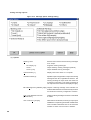
Target Device
V800 SeriesTM
Compatible Compilers
CA830 Ver.1.10 or later
CA850 Ver.2.00 or later
Document No. U12827EJ1V0UM00 (1st edition)
Date Published November 1997 N
©
1997
Printed in Japan
1
[MEMO]
2
Trademarks
• V800 Series, V810 Family, V830 Family, V850 Family, V810, V830, V851, and V850E are trademarks of NEC
Corporation.
• Windows, Windows NT, Win32s, Win32, and MS-DOS are either registered trademarks or trademarks of Microsoft
Corporation in the United States and/or other countries.
• The other company names and product names appearing in this document are the trademarks of their respective
companies.
3
The information in this document is subject to change without notice.
No part of this document may be copied or reproduced in any form or by any means without the prior written
consent of NEC Corporation. NEC Corporation assumes no responsibility for any errors which may appear in
this document.
NEC Corporation does not assume any liability for infringement of patents, copyrights or other intellectual
property rights of third parties by or arising from use of a device described herein or any other liability arising
from use of such device. No license, either express, implied or otherwise, is granted under any patents,
copyrights or other intellectual property rights of NEC Corporation or of others.
4
Regional Information
Some information contained in this document may vary from country to country. Before using any NEC
product in your application, please contact the NEC office in your country to obtain a list of authorized
representatives and distributors. They will verify:
• Device availability
• Ordering information
• Product release schedule
• Availability of related technical literature
• Development environment specifications (for example, specifications for third-party tools and
components, host computers, power plugs, AC supply voltages, and so forth)
• Network requirements
In addition, trademarks, registered trademarks, export restrictions, and other legal issues may also vary
from country to country.
NEC Electronics Inc. (U.S.)
NEC Electronics (Germany) GmbH
NEC Electronics Hong Kong Ltd.
Santa Clara, California
Tel: 408-588-6000
800-366-9782
Fax: 408-588-6130
800-729-9288
Benelux Office
Eindhoven, The Netherlands
Tel: 040-2445845
Fax: 040-2444580
Hong Kong
Tel: 2886-9318
Fax: 2886-9022/9044
NEC Electronics Hong Kong Ltd.
Velizy-Villacoublay, France
Tel: 01-30-67 58 00
Fax: 01-30-67 58 99
Seoul Branch
Seoul, Korea
Tel: 02-528-0303
Fax: 02-528-4411
NEC Electronics (France) S.A.
NEC Electronics Singapore Pte. Ltd.
Milton Keynes, UK
Tel: 01908-691-133
Fax: 01908-670-290
Spain Office
Madrid, Spain
Tel: 01-504-2787
Fax: 01-504-2860
United Square, Singapore 1130
Tel: 253-8311
Fax: 250-3583
NEC Electronics Italiana s.r.1.
NEC Electronics (Germany) GmbH
Milano, Italy
Tel: 02-66 75 41
Fax: 02-66 75 42 99
Scandinavia Office
Taeby, Sweden
Tel: 08-63 80 820
Fax: 08-63 80 388
NEC Electronics (France) S.A.
NEC Electronics (Germany) GmbH
Duesseldorf, Germany
Tel: 0211-65 03 02
Fax: 0211-65 03 490
NEC Electronics (UK) Ltd.
NEC Electronics Taiwan Ltd.
Taipei, Taiwan
Tel: 02-719-2377
Fax: 02-719-5951
NEC do Brasil S.A.
Cumbica-Guarulhos-SP, Brasil
Tel: 011-6465-6810
Fax: 011-6465-6829
J97. 8
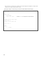
5
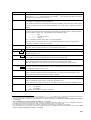
Revision History
Edition
Date of Issue
01
November, 1997
6
Description (reason)
First edition
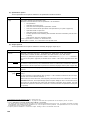
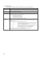
INTRODUCTION
[Target Device]
The V800 SeriesTM C Compiler Package creates the object codes for the NEC’s V800 Series RISC microprocessors,
which are compatible with each family.
The V830 FamilyTM inherits the basic instruction set of the V810 FamilyTM. Therefore, the software resource
of the V810 Family can be used without modification.
[Target Users]
This manual is intended for users who develop application systems using the V800 Series C Compiler Package
under WindowsTM.
[Objective]
This manual explains how to operate the commands, which are included in C compiler and assembler in each
package, under Windows.
A Project Manager is included in these C compiler packages. For operation methods for integrated development,
refer to the User’s Manual of Project Manager.
For operation of Windows, refer to the function guide or others including in the Windows.
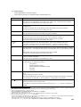
[Organization]
This manual consists of the following contents.
• Overview of this compiler package
• How to use this compiler package via Project Manager
• How to use this compiler package in a command line
• Command functions, options, and output messages
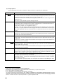
Commands Included in Package
C compiler (ca)
Assembler (as)
Link editor (ld)
Archiver (ar)
Hex converter (hx)
Dump command (dump)
Disassembler (dis)
ROM-storing processor (romp)
Section file generator (sf)
* V850
7
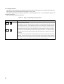
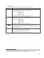
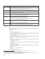
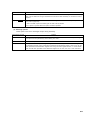
[Cautions]
• This document describes two families (CA830 and CA850). The functions peculiar to a certain family are
specified by title names and symbols in the text such as * V830 and * V850 . Unless otherwise specified,
the description in this document apply to all the families.
A description using a command name of a specific family is also applied to all the families unless otherwise
specified.
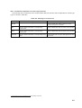
• In a description that applies to all the families, the package name and directory name are abbreviated as
“ca” and “libxxx”. These package names and file names should be taken as follows, depending on the
device used.
Package name
CA
: CA830 or CA850
Command name
ca
: ca830 or ca850
as
: as830 or as850
:
Directory name
libxxx : lib830 or lib850
• The functions peculiar to “V850ETM” in the V850 FamilyTM are specified by title name or the symbol such as
“* V850E ”.
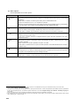
[Related Documents]
• V800 Series C Compiler Package User’s Manual - C Language
• CA830 C Compiler Package User’s Manual - Assembly Language
• CA850 C Compiler Package User’s Manual - Assembly Language
• V800 Series Microprocessor User’s Manual
• Project Manager User’s Manual
Published by NEC Corporation
• Attached manuals to Microsoft TM Windows such as Microsoft Windows Operating System Function Guide
Published by Microsoft Corporation
• Programming Language C, 2nd edition, conforming to ANSI standard
B.W. Kernihang, D.M. Riche, translated by Haruhisa Ishida
Published by Kyoritsu Publishing Co.
8
CONTENTS
VOLUME 1 GENERAL ........................................................................................................... 21
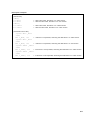
CHAPTER 1 OVERVIEW ......................................................................................................................... 22
1.1 Organization of This Manual ....................................................................................... 22
1.2 Features of CA Windows-based Compiler Package ............................................... 23
CHAPTER 2
2.1
2.2
2.3
2.4
2.5
INSTALLATION ...................................................................................................................25
Operating Environment ................................................................................................ 25
Installation ...................................................................................................................... 26
Directory Configuration ................................................................................................ 27
Library File ...................................................................................................................... 28
Cautions .......................................................................................................................... 29
VOLUME 2 OPERATION METHODS ................................................................................... 31
CHAPTER 1 OVERVIEW OF OPERATIONS ........................................................................................... 32
CHAPTER 2
2.1
2.2
2.3
2.4
2.5
OPERATIONS USING THE PROJECT MANAGER ........................................................... 33
What is the Project Manager? ..................................................................................... 33
Activation of Project Manager .................................................................................... 34
Project Settings ............................................................................................................. 35
Project Manager and CA .............................................................................................. 37
Dialogs for Setting CA Command Options ............................................................... 39
2.5.1
Setting compiler options .................................................................................................. 39
Setting input options ........................................................................................................ 42
Setting pre-processor options ........................................................................................ 44
Setting language options ................................................................................................. 46
Setting optimization options ........................................................................................... 48
Setting output 1 options ................................................................................................... 50
Setting output 2 options ................................................................................................... 53
Setting message options .................................................................................................. 56
Setting other options ........................................................................................................ 58
2.5.2
Setting assembler options ............................................................................................... 60
Setting option 1 .................................................................................................................. 61
Setting option 2 .................................................................................................................. 63
Setting other options ........................................................................................................ 66
2.5.3
Setting link editor options ............................................................................................... 68
Setting files ......................................................................................................................... 69
Setting options ................................................................................................................... 71
Setting other options ........................................................................................................ 74
2.5.4
Setting ROM-storing processor options ....................................................................... 76
Setting options ................................................................................................................... 77
Setting other options ........................................................................................................ 79
2.6 Creating and Building Make Files .............................................................................. 80
2.6.1
Using menu to create make files .................................................................................... 80
2.6.2
Auto generation of make file via build function .......................................................... 81
9
CHAPTER 3
3.1
3.2
3.3
USE OF COMMAND SHELL .............................................................................................. 84
What is VSH? .................................................................................................................. 84
Activation of VSH .......................................................................................................... 84
Function of VSH ............................................................................................................. 85
3.3.1
Command line editing function ....................................................................................... 86
3.3.2
Scroll functions .................................................................................................................. 87
3.3.3
History function ................................................................................................................. 88
3.3.4
Alias function ..................................................................................................................... 89
3.3.5
Menus ................................................................................................................................... 90
3.4 Activation of Commands from VSH ........................................................................... 99
3.4.1
Operations related to internal commands only ........................................................... 99
3.4.2
Operations related to external commands only ........................................................ 100
3.4.3
Operations related to all commands ............................................................................ 100
3.5 VSH Internal Commands ............................................................................................ 102
3.6 Activation of CA Commands ..................................................................................... 137
CHAPTER 4
4.1
4.2
4.3
3.6.1
Activation from command line ...................................................................................... 137
3.6.2
Output file specification in VSH ................................................................................... 138
USE OF MAKE UTILITY ................................................................................................... 139
What is VMAKE? .......................................................................................................... 139
Features of VMAKE ..................................................................................................... 139
Operation ....................................................................................................................... 140
4.3.1
VMAKE input syntax ........................................................................................................ 140
4.3.2
List of options .................................................................................................................. 141
4.4 Make Files ..................................................................................................................... 142
4.4.1
Comments ......................................................................................................................... 142
4.4.2
Continuation of lines ....................................................................................................... 142
4.4.3
Description of targets ..................................................................................................... 142
4.4.4
Command lines ................................................................................................................. 144
4.4.5
Macros ................................................................................................................................ 144
VOLUME 3
HANDLING C COMPILER ............................................................................. 147
CHAPTER 1
1.1
1.2
1.3
OVERVIEW ....................................................................................................................... 148
Flow of Operation ........................................................................................................ 148
Handling File ................................................................................................................ 150
Execution Object Creating Pattern .......................................................................... 151
CHAPTER 2 OPERATION ...................................................................................................................... 153
2.1 Command Input Format from VSH Command Line .............................................. 153
2.2 Types and Features of Options ................................................................................ 153
2.2.1
Option list .......................................................................................................................... 153
(1) Input options ............................................................................................................. 153
(2) Preprocessing options ............................................................................................ 154
(3) Language options ..................................................................................................... 155
(4) Optimization option .................................................................................................. 156
(5) Output options .......................................................................................................... 156
(6) Message options ....................................................................................................... 158
(7) Other options ............................................................................................................. 159
10
2.2.2
Efficient use of optimization ......................................................................................... 162
2.2.3
Effects of debugging on optimization ......................................................................... 165
2.2.4
Output of bdld instruction * V830 ................................................................................. 166
2.2.5
Argument of -W option ................................................................................................... 172
2.3 Cautions on Specifying Options .............................................................................. 174
2.4 Example ......................................................................................................................... 174
CHAPTER 3 MESSAGES ...................................................................................................................... 175
3.1 Message Format ........................................................................................................... 175
3.2 Messages ...................................................................................................................... 176
VOLUME 4 HANDLING ASSEMBLER ............................................................................... 199
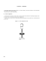
CHAPTER 1 OVERVIEW ....................................................................................................................... 200
1.1 Flow of Operation ........................................................................................................ 200
1.2 Handling File ................................................................................................................ 200
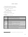
CHAPTER 2 OPERATION ...................................................................................................................... 201
2.1 Command Input Format from VSH Command Line .............................................. 201
2.2 Types and Features of Options ................................................................................. 201
2.2.1
Option list .......................................................................................................................... 201
(1) Optimization option .................................................................................................. 201
(2) Output options .......................................................................................................... 202
(3) Message options ....................................................................................................... 203
(4) Other options ............................................................................................................. 204
2.3 Example ......................................................................................................................... 207
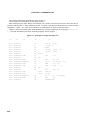
CHAPTER 3 ASSEMBLE LIST .............................................................................................................. 208
CHAPTER 4 MESSAGES ...................................................................................................................... 210
4.1 Message Format ........................................................................................................... 210
4.2 Messages ...................................................................................................................... 210
VOLUME 5 HANDLING LINK EDITOR .............................................................................. 217
CHAPTER 1 OVERVIEW ....................................................................................................................... 218
1.1 Flow of Operation ........................................................................................................ 218
1.1.1
Link procedure ................................................................................................................. 220
CHAPTER 2 OPERATION ...................................................................................................................... 222
2.1 Command Input Format from VSH Command Line .............................................. 222
2.2 Types and Features of Options ................................................................................ 222
2.2.1
Option list .......................................................................................................................... 222
(1) File options ................................................................................................................ 223
(2) Check options ........................................................................................................... 224
(3) Message options ....................................................................................................... 224
(4) Other options ............................................................................................................. 225
2.2.2
Using options ................................................................................................................... 226
CHAPTER 3 LINK DIRECTIVE .............................................................................................................. 254
3.1 Feature of Link Directive ............................................................................................ 254
3.2 Configuration of Link Directive ................................................................................ 255
11
3.3 Section and Segment .................................................................................................. 256
3.3.1
Type of section ................................................................................................................. 257
3.3.2
Examples of mapping image ......................................................................................... 259
3.4 Segment Directive ....................................................................................................... 264
3.4.1
Feature of segment directive ......................................................................................... 264
3.4.2
Configuration of segment directive ............................................................................. 264
3.4.3
Explanation of each item that can be specified for segment directive ................ 266
3.4.4
Using segment directive ................................................................................................. 274
3.5 Mapping Directive ........................................................................................................ 278
3.5.1
Feature of mapping directive ........................................................................................ 278
3.5.2
Configuration of mapping directive ............................................................................. 278
3.5.3
Explanation of each item that can be specified for mapping directives .............. 279
3.5.4
Using mapping directive ................................................................................................ 286
3.6 Symbol Directive.......................................................................................................... 290
3.6.1
Feature of symbol directive ........................................................................................... 290
3.6.2
Configuration of symbol directive ................................................................................ 292
3.6.3
Explanation of each item that can be specified for symbol directives ................ 294
3.6.4
Using symbol directive ................................................................................................... 296
3.6.5
tp symbol offset in label reference .............................................................................. 302
3.7 Default Link Directive ................................................................................................. 305
3.8 Using Default Link Directive ..................................................................................... 315
3.9 Syntax of Link Directive ............................................................................................. 316
CHAPTER 4 LINK MAP ......................................................................................................................... 318
CHAPTER 5
5.1
5.2
5.3
5.4
SUPPLEMENT .................................................................................................................. 320
Using Archive File ....................................................................................................... 320
Reserved Symbols ....................................................................................................... 320
File Name in Link Directive ....................................................................................... 322
Link between V850 Family Object File and V850E Object File ........................... 322
CHAPTER 6 MESSAGES ...................................................................................................................... 323
6.1 Message Format ........................................................................................................... 323
6.2 Messages ...................................................................................................................... 324
VOLUME 6
HANDLING ARCHIVER .................................................................................. 335
CHAPTER 1 OVERVIEW ....................................................................................................................... 336
1.1 Flow of Operation ........................................................................................................ 336
1.2 Handling File ................................................................................................................ 336
CHAPTER 2 OPERATION ...................................................................................................................... 337
2.1 Command Input Format from VSH Command Line .............................................. 337
2.2 Types and Features of Keys/Options ...................................................................... 337
2.2.1
Key list ............................................................................................................................... 337
2.2.2
Option list .......................................................................................................................... 338
2.3 Examples of Use .......................................................................................................... 338
CHAPTER 3 MESSAGES ...................................................................................................................... 339
3.1 Message Format ........................................................................................................... 339
3.2 Messages ...................................................................................................................... 339
12
VOLUME 7 HANDLING HEX CONVERTER ...................................................................... 341
CHAPTER 1 OVERVIEW ....................................................................................................................... 342
1.1 Flow of Operation ........................................................................................................ 342
1.2 Handling File ................................................................................................................ 343
CHAPTER 2 OPERATION ...................................................................................................................... 344
2.1 Command Input Format from VSH Command Line .............................................. 344
2.2 Types and Features of Options ................................................................................ 344
2.2.1
Option list .......................................................................................................................... 344
2.3 Examples of Use .......................................................................................................... 345
CHAPTER 3
3.1
3.2
3.3
TYPES OF OUTPUT FILES .............................................................................................. 346
Intel Expanded Hex Format ....................................................................................... 346
Motorola S Type Hex Format ..................................................................................... 349
Expanded Tek Hex Format ......................................................................................... 352
CHAPTER 4 MESSAGES ...................................................................................................................... 356
4.1 Message Format ........................................................................................................... 356
4.2 Messages ...................................................................................................................... 356
VOLUME 8 HANDLING DUMP COMMAND ...................................................................... 359
CHAPTER 1 OVERVIEW ....................................................................................................................... 360
1.1 Flow of Operation ........................................................................................................ 360
CHAPTER 2 OPERATION ...................................................................................................................... 361
2.1 Command Input Format from VSH Command Line .............................................. 361
2.2 Types and Features of Options ................................................................................ 361
2.2.1
Option list .......................................................................................................................... 361
2.3 Examples of Use .......................................................................................................... 362
CHAPTER 3 DISPLAY FORMAT ........................................................................................................... 363
3.1 Archive Header ............................................................................................................. 363
3.2 Archive Symbol Table ................................................................................................. 363
3.3 Archive String Table ................................................................................................... 363
3.4 ELF Header ................................................................................................................... 364
3.5 Program Header Table ................................................................................................ 364
3.6 Section Header Table .................................................................................................. 364
3.7 String Table ................................................................................................................... 365
3.8 Symbol Table ................................................................................................................ 365
3.9 Relocation Information ............................................................................................... 365
3.10 Register Mode Information ........................................................................................ 365
3.11 Global Pointer Table ................................................................................................... 366
3.12 Line Number Information ........................................................................................... 366
3.13 Debug Information ....................................................................................................... 366
3.14 PROGBITS Data ........................................................................................................... 366
3.15 Element Values and Meanings .................................................................................. 367
CHAPTER 4 MESSAGES ...................................................................................................................... 369
4.1 Message Format ........................................................................................................... 369
4.2 Messages ...................................................................................................................... 369
13
VOLUME 9 HANDLING DISASSEMBLER ......................................................................... 371
CHAPTER 1 OVERVIEW ....................................................................................................................... 372
1.1 Flow of Operation ........................................................................................................ 372
CHAPTER 2 OPERATION ...................................................................................................................... 373
2.1 Command Input Format from VSH Command Line .............................................. 373
2.2 Types and Features of Options ................................................................................ 373
2.2.1
Option list .......................................................................................................................... 373
2.3 Cautions ........................................................................................................................ 374
2.4 Examples of Use .......................................................................................................... 374
2.5 Output Example ........................................................................................................... 375
CHAPTER 3 MESSAGES ...................................................................................................................... 376
3.1 Message Format ........................................................................................................... 376
3.2 Messages ...................................................................................................................... 376
VOLUME 10 HANDLING ROM-STORING PROCESSOR ................................................ 377
CHAPTER 1
1.1
1.2
1.3
OVERVIEW ....................................................................................................................... 378
Flow of Operation ........................................................................................................ 378
Types of Sections to Be Packed ............................................................................... 380
Procedure of Storing to ROM .................................................................................... 381
CHAPTER 2 OPERATION ...................................................................................................................... 384
2.1 Command Input Format .............................................................................................. 384
2.2 Types and Features of Options ................................................................................ 384
2.2.1
Option list .......................................................................................................................... 384
(1) Output options .......................................................................................................... 384
(2) Other options ............................................................................................................. 385
2.3 Examples of Use .......................................................................................................... 385
CHAPTER 3 ALLOCATING AREA OF rompsec SECTION AND LINK PROCEDURE ........................ 386
3.1 Allocation Area of rompsec Section ........................................................................ 386
3.2 rompsec Section and Link Directive ....................................................................... 387
CHAPTER 4 COPY ROUTINE ............................................................................................................... 391
CHAPTER 5 MESSAGES ...................................................................................................................... 394
5.1 Message Format ........................................................................................................... 394
5.2 Messages ...................................................................................................................... 394
VOLUME 11 HANDLING SECTION FILE GENERATOR.................................................. 397
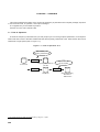
CHAPTER 1 OVERVIEW ....................................................................................................................... 398
1.1 Flow of Operation ........................................................................................................ 398
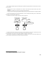
1.2 Sequence to Use Section File ................................................................................... 400
CHAPTER 2 OPERATION ...................................................................................................................... 402
2.1 Command Input Format .............................................................................................. 402
2.2 Types and Features of Options ................................................................................ 402
2.2.1
Option list .......................................................................................................................... 402
2.3 Examples of Use .......................................................................................................... 404
14
CHAPTER 3 MESSAGES ...................................................................................................................... 405
3.1 Message Format ........................................................................................................... 405
3.2 Messages ...................................................................................................................... 405
APPENDIX .............................................................................................................................. 407
APPENDIX A SECTION FILES .............................................................................................................. 408
APPENDIX B
B.1
B.2
B.3
B.4
FORMAT OF OBJECT FILE ............................................................................................ 412
Structure of Object File .............................................................................................. 412
ELF Header ................................................................................................................... 413
Program Header Table ................................................................................................ 414
Section Header Table .................................................................................................. 415
B.4.1 Section type ...................................................................................................................... 416
B.4.2 Constituents dependent on section type (link/info) ................................................. 417
B.5 Section ........................................................................................................................... 418
B.5.1 Symbol table ..................................................................................................................... 419
B.5.2 String table ........................................................................................................................ 420
B.5.3 Reserved section ............................................................................................................. 421
B.6 Segment ......................................................................................................................... 422
INDEX ......................................................................................................................................................423
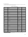
15
LIST OF FIGURES
Figure No.
Title
Page
VOLUME 1 GENERAL
1-1.
Package Organization Figure ............................................................................................................. 24
2-1.
Directory Configuration ....................................................................................................................... 27
VOLUME 2 OPERATION METHODS
1-1.
Outline of CA Package Operations .................................................................................................... 32
2-1.
Project Manager and Development Tools .......................................................................................... 33
2-2.
Window for Activation of Project Manager ......................................................................................... 34
2-3.
Outline of CA Option Specification from Project Manager ................................................................ 37
2-4.
Window for Setting Project File .......................................................................................................... 38
2-5.
Project Manager’s Option Menu (after setting project) ..................................................................... 38
2-6.
Delete Source Option Button .............................................................................................................. 40
2-7.
Input Option Settings Dialog ............................................................................................................... 42
2-8.
Pre-processor Option Settings Dialog ................................................................................................ 44
2-9.
Language Option Settings Dialog ...................................................................................................... 46
2-10.
Optimization Option Settings Dialog .................................................................................................. 48
2-11.
Output 1 Option Settings Dialog ......................................................................................................... 50
2-12.
Output 2 Option Settings Dialog ......................................................................................................... 53
2-13.
Message Option Settings Dialog ........................................................................................................ 56
2-14.
Other Option Settings Dialog (C Compiler) ....................................................................................... 58
2-15.
Delete Source Option Button .............................................................................................................. 60
2-16.
Option 1 Settings Dialog (Assembler) ................................................................................................ 61
2-17.
Option 2 Settings Dialog (Assembler) ................................................................................................ 63
2-18.
Other Option Settings Dialog (Assembler) ......................................................................................... 66
2-19.
File Settings Dialog ............................................................................................................................. 69
2-20.
Option Settings Dialog (Link Editor) ................................................................................................... 71
2-21.
Other Option Settings Dialog (Link Editor) ........................................................................................ 74
2-22.
Option Settings Dialog (ROM-Storing Processor) ............................................................................. 77
2-23.
Other Option Settings Dialog (ROM-Storing Processor) ................................................................... 79
3-1.
VSH Window ....................................................................................................................................... 84
3-2.
History Search Examples ................................................................................................................... 89
3-3.
Example of CA Command Activation from VSH .............................................................................. 137
4-1.
Position of VMAKE ............................................................................................................................ 139
VOLUME 3 HANDLING C COMPILER
1-1.
16
Operation Flow of ca ......................................................................................................................... 149
LIST OF FIGURES
Figure No.
2-1.
Title
Page
Optimization Levels and Parameters ............................................................................................... 162
VOLUME 4 HANDLING ASSEMBLER
1-1.
Flow of Operation of as .................................................................................................................... 200
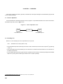
2-1.
Image of Creating Common Object with as ..................................................................................... 205
3-1.
Example of Output Assemble List .................................................................................................... 208
VOLUME 5 HANDLING LINK EDITOR
1-1.
Flow of Operation by ld ..................................................................................................................... 219
1-2.
Example of Image of Operation by ld .............................................................................................. 219
2-1.
Image of Memory Location of gp Offset Reference Section ........................................................... 226
3-1.
Section and Segment ........................................................................................................................ 256
3-2.
Memory Location of Reserved Section ............................................................................................ 258
3-3.
Example of Mapping Image 1 ........................................................................................................... 259
3-4.
Example of Mapping Image 2 ........................................................................................................... 260
3-5.
Example of Mapping Image 3 ........................................................................................................... 261
3-6.
Example of Mapping Image 4 ........................................................................................................... 262
3-7.
Example of Mapping Image 5 ........................................................................................................... 263
3-8.
Configuration of Segment Directive ................................................................................................. 264
3-9.
General Format of Allocation with Address Specified ..................................................................... 274
3-10.
Example of Allocation Display with Address Specified .................................................................... 274
3-11.
Example of Allocation with Address Specified ................................................................................. 275
3-12.
General Format of Allocation with Alignment Condition Specified ................................................. 275
3-13.
Example of Allocation Display with Alignment Condition Specified ................................................ 276
3-14.
Example of Allocation with Alignment Condition Specified ............................................................. 276
3-15.
General Format of Allocation with Creating Hole Specified ............................................................ 277
3-16.
Example of Allocation with Creating Hole Specified ....................................................................... 277
3-17.
Configuration of Mapping Directive .................................................................................................. 278
3-18.
General Format to Link Object Files ................................................................................................ 289
3-19.
Example of Commands for Linking Object Files ............................................................................. 289
3-20.
Example of Linking Object Files ....................................................................................................... 289
3-21.
Configuration of Symbol Directive .................................................................................................... 292
3-22.
Rules to Determine gp Symbol Value .............................................................................................. 293
3-23.
General Format to Create tp/gp/ep Symbols ................................................................................... 296
3-24.
Example of Commands for Creating One Each of tp/gp/ep Symbols ............................................ 297
3-25.
Example of Creating One Each of tp/gp/ep Symbols ...................................................................... 298
3-26.
Example of Commands for Creating Two or More tp/gp Symbols ................................................. 300
17
LIST OF FIGURES
Figure No.
Title
Page
3-27.
Example of Creating Two or More tp/gp Symbols ........................................................................... 301
3-28.
Example of Link Directive Where label Reference is tp Symbol Offset ......................................... 302
3-29.
Example of Assembler Codes of a.o through c.o ............................................................................ 303
3-30.
Default Link Directive (CA830: V830) .............................................................................................. 306
3-31.
Memory Location by Default Link Directive (CA830) ...................................................................... 308
3-32.
Default Link Directive with SIDATA (CA850: V851) ......................................................................... 310
3-33.
Memory Location by Default Link Directive (CA850: with internal ROM) ...................................... 311
3-34.
Default Link Directive without SIDATA (CA850: V851) .................................................................... 312
3-35.
Memory Location by Default Link Directive (CA850: with internal ROM) ...................................... 313
4-1.
Output Example of Link Map ............................................................................................................ 318
VOLUME 6 HANDLING ARCHIVER
1-1.
Flow of Operation of ar ..................................................................................................................... 336
VOLUME 7 HANDLING HEX CONVERTER
1-1.
Flow of Operation of hx .................................................................................................................... 342
3-1.
File Configuration in Intel Expanded Hex Format ........................................................................... 346
3-2.
File Configuration in Motorola S Type Hex Format ......................................................................... 349
3-3.
File Configuration in Expanded Tek Hex Format ............................................................................. 352
VOLUME 8 HANDLING DUMP COMMAND
1-1.
Flow of Operation of dump ............................................................................................................... 360
VOLUME 9 HANDLING DISASSEMBLER
1-1.
Flow of Operation of dis .................................................................................................................... 372
VOLUME 10 HANDLING ROM-STORING PROCESSOR
1-1.
Flow of Operation of romp ................................................................................................................ 378
1-2.
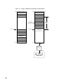
Example of Using Copy Routine _rcopy .......................................................................................... 381
1-3.
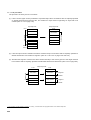
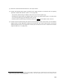
Image of ROM Storing (example of V830 Family) .......................................................................... 382
1-4.
Image of ROM Storing (example of V850 Family) .......................................................................... 383
VOLUME 11 HANDLING SECTION FILE GENERATOR
1-1.
18
Flow of Operation of sf ..................................................................................................................... 398
LIST OF FIGURES
Figure No.
Title
Page
APPENDIX
B-1.
Structure of Object File ..................................................................................................................... 412
B-2.
Relationships between Index and Character String in String Table ............................................... 420
19
LIST OF TABLES
Table No.
Title
Page
VOLUME 2 OPERATION METHODS
3-1.
Edit Key Lists ...................................................................................................................................... 86
3-2.
Keys for Operating Vertical Scroll Bar ............................................................................................... 87
3-3.
Keys for Operating History Function .................................................................................................. 88
3-4.
List of VSH Internal Commands ....................................................................................................... 102
VOLUME 4 HANDLING ASSEMBLER
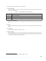
3-1.
Section Attributes and Their Meanings ............................................................................................ 209
VOLUME 5 HANDLING LINK EDITOR
3-1.
Types of Sections .............................................................................................................................. 257
3-2.
Items That Can Be Specified and Their Specification Formats ...................................................... 264
3-3.
Default Value of Each Item ............................................................................................................... 265
3-4.
Segment Attributes and Their Meanings .......................................................................................... 268
3-5.
Items That Can Be Specified and Their Specification Formats ...................................................... 278
3-6.
Section Attributes and Their Meanings ............................................................................................ 282
5-1.
Special Symbols in Normal Object File ............................................................................................ 321
VOLUME 10 HANDLING ROM-STORING PROCESSOR
1-1.
Reserved Sections Packed by romp ................................................................................................ 380
APPENDIX
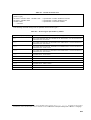
20
A-1.
Format of Section File ....................................................................................................................... 409
A-2.
Section Types Specifiable by CA830 ............................................................................................... 409
A-3.
Section Types Specifiable by CA850 ............................................................................................... 410
B-1.
Constituents of ELF Header and Their Meanings ........................................................................... 413
B-2.
Constituents of Program Header Table Entry and Their Meanings ................................................ 414
B-3.
Constituents of Section Header Table Entry and Their Meanings .................................................. 415
B-4.
Section Types and Their Meanings .................................................................................................. 416
B-5.
Meanings of link and info .................................................................................................................. 417
B-6.
Constituents of Symbol Table Entry and Their Meanings ............................................................... 419
B-7.
Reserved Sections ............................................................................................................................ 421
VOLUME 1
GENERAL
21
CHAPTER 1 OVERVIEW
This chapter explains the organization of this manual and the features of the CA WindowsTM-based compiler
packages.
1.1 Organization of This Manual
This manual consists of the following volumes and appendix.
VOLUME 1 GENERAL
Explains the organization of this manual and the operating environment of the CA830/CA850 compiler packages.
VOLUME 2 OPERATION METHOD
Explains the handling method of the CA830/CA850 compiler packages for Windows and the Make Utility
(VMAKE) of the command line interface.
VOLUME 3 HANDLING C COMPILER
Explains the C compiler (ca).
VOLUME 4 HANDLING ASSEMBLER
Explains the assembler (as).
VOLUME 5 HANDLING LINK EDITOR
Explains the link editor (ld).
VOLUME 6 HANDLING ARCHIVER
Explains the archiver (ar).
VOLUME 7 HANDLING HEX CONVERTER
Explains the hex converter (hx).
VOLUME 8 HANDLING DUMP COMMAND
Explains the dump command (dump).
VOLUME 9 HANDLING DISASSEMBLER
Explains the disassembler (dis).
VOLUME 10 HANDLING ROM-STORING PROCESSOR
Explains the ROM-storing processor (romp).
VOLUME 11 HANDLING SECTION FILE GENERATOR
Explains the section file generator (sf).
APPENDIX
Explains the format of the section file and object file.
22
1.2 Features of CA Windows-based Compiler Package
The CA830/CA850 Compiler Packages have the following features:
• Language specifications conforming to ANSI standard
The C language specifications conform to the ANSI standard and are also compatible with the conventional
C language (K&R specifications).
• High-level optimization
The C compiler/assembler provide multi-level optimization.
• Features for embedded control
A utility is provided to facilitate storing the application system to ROM.
• Easy description
The expanded language specifications facilitate the description of programs in C language.
The CA830/CA850 Windows-based C compiler packages are provided with the following operating features.
• Activation from Project Manager
CA can be activated from efficient integrated environment (Project Manager).
The Project Manager is a control software that allows tools operating in Windows to activate efficiently and
is included in this compiler package.
• Shell function added
Because shell function (VSH) is added in CA, the activation from command interface is possible.
23
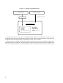
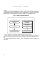
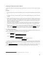
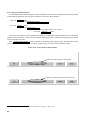
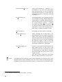
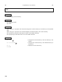
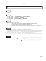
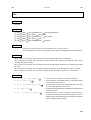
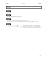
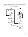
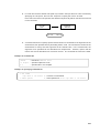
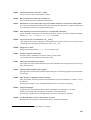
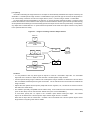
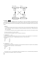
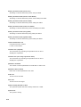
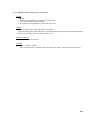
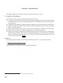
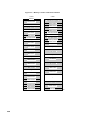
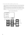
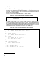
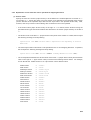
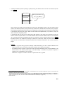
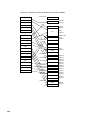
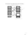
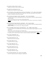
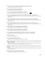
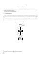
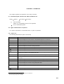
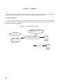
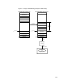
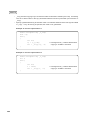
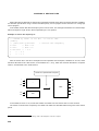
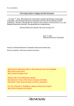
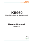
Figure 1-1. Package Organization Figure
Project Manager
Shell for CA (VSH)
Specifying Option
Command line initiation
Tool DLL
CA Package Command
C Compiler
Assembler
Link Editor
ROM-storing processor
Archiver
Hex converter
Disassembler
Dump command
Section file generator
* V850
The Project Manager runs on Windows and supplies graphical application development environments, so that
an application load module can be created by specifying an option of the C compiler, assembler, or link editor can
be specified from the Project Manager to automatically execute their commands.
The V800 Series C compiler package also supplies a shell (VSH) function as an application development
environment on the command line. VSH allows utility tools such as archiver and hex converter, in addition to the
C compiler, assembler, link editor, and ROM-storing processor, to run like the command line of MS-DOSTM prompt.
24
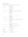
CHAPTER 2 INSTALLATION
This chapter explains the operating environment, installation of supplied medium and points to be noted of this
compiler package.
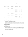
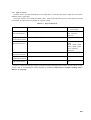
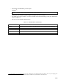
2.1 Operating Environment
This compiler package runs in the following environments:
Machine
Machine which can operate Microsoft Windows 95
Operating System
Microsoft Windows 95
Hard Disk
10 MB of empty capacity
Operating Memory
32 MB
[Cautions]
• Microsoft Windows 95 creates swap file in windows folder when various tools are operated. Always keep
enough empty capacity in the drive where the windows folder is installed.
• The operation of CA is not guaranteed in Microsoft Windows for OS/2TM.
For the processing of the CA command, a device file (refer to -cpu option on page 159) dependent on the
target device is necessary1.
1
The device file is separately available.
25
2.2 Installation
This package consists of six FDs2.
The read-out method of the files of the C compiler package (including Project Manager) is explained below.
(1) Insert Setup Disk 1 (1/6) of the C compiler package into the FD drive of the host machine.
(2) Execute the SETUP.EXE command, which is in the root directory of the FD, with Explorer in Windows.
Install the C compiler following the instructions.
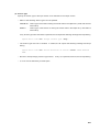
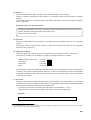
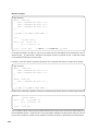
(3) Set the command search path. Set the bin directory under install directory to the environmental variable
PATH in batch file autoexec.bat. In the PATH of autoexec.bat, add the bin directory under the install
directory or the following description after environmental variable PATH3. Note that the environmental
variable PATH recognizes up to 128 characters.
PATH
%PATH%;A\NECTOOLS\BIN
(4) Restart Windows.
By restarting Windows, new autoexec.bat is executed, necessary device drivers are set, and Project
Manager and CA can be used.
2
3
7 FDs for Japanese version.
The mark “ ” indicates a blank space.
26
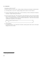
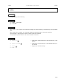
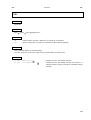
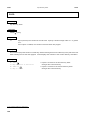
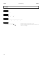
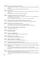
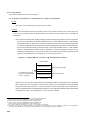
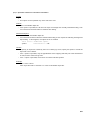
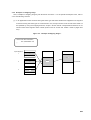
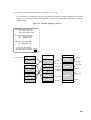
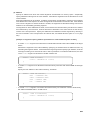
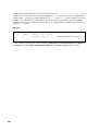
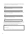
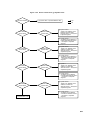
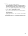
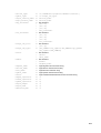
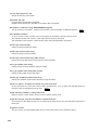
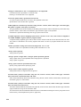
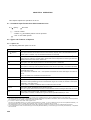
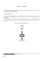
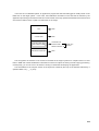
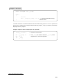
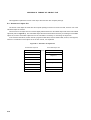
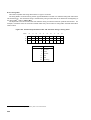
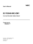
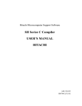
2.3 Directory Configuration
The configuration of the directory of the files read from the supply media as a result of installing this compiler
package is shown in Figure 2-14.
The default of install directory is "\NECTOOLS" in the drive where the Windows system is located.
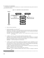
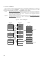
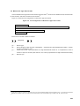
Figure 2-1. Directory Configuration
bin
Command group, VSH, VMAKE,
and project manager
incxxx
Include file group
lib
Modules internally called by C compiler
[New function calling specification]
r22
Library (for 22-register mode)
start-up module
r26
Library (for 26-register mode)
start-up module
r32
Library (for 32-register mode)
start-up module
libxxx
Install directory
[Old function calling specification] * V850
Library (for 22-register mode)
r22old
start-up module
smpxxx
r26old
Library (for 26-register mode)
start-up module
r32old
Library (for 32-register mode)
start-up module
caxxx
Sample of link directive
hlp
On-line manual
doc
Release note (.txt file)
Be sure to set the above bin directory to the command search path when installing the compiler package (refer
to page 26).
The old function calling is not supplied in the CA830.
The library/start-up module for the old function calling specification is not included in the supply media of the
CA830.
Even in the CA850, the old function calling is not supplied when the V850ETM is used for the target device.
4
In this compiler package, directory libxxx and r32 under libxxx in Figure 2-1 is called the standard directory for the library, directory incxxx is
called the standard directory for the include file, and the standard directory for the device file becomes the dev directory in the same level.
27
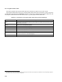
2.4 Library File
The header files and standard/mathematical libraries of this compiler package are “libc” in the following copyright
statement transplanted by Cygnus Support for the V810 Family and then by NEC Corporation for the V830
Family and V850 Family.
Copyright 1992, 1993, 1994, Cygnus Support
“libc” includes software developed by Berkley University in California, and others.
Copying this document and distributing the copy are permitted only if the copyright statement and
this permission statement remain in all copies.
The permission to copy and distribute copies of the revised edition of this document verbatim is
granted under the conditions of the GNU General Public License. This GNU General Public License
includes a stipulation that all the results obtained by using “libc” are to be distributed according to
the same permission statement.
The permission to translate this document into other languages and to copy and distribute the copy
of the translated version is granted under the condition of the revised edition mentioned above.
“This document” in the above mentioned statement means an explanation of each function included in the
standards and mathematical libraries explained in V800 Series C Compiler Package User’s Manual-C language.
The ROM-storing library as well as the run-time library and emulation library added to the standard library are
the original functions of NEC Corporation.
28
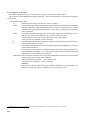
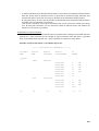
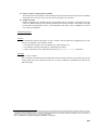
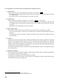
2.5 Cautions
• This compiler package creates a temporary file used internally under the following directory (The number
indicates the priority).
– To start from Project Manager
1.
Work directory set by <<Other settings>> of <<Project Manager option setting>> dialog which is
displayed by
Option
→
Project Manager Options...
2.
Directory specified by environmental variable TEMP
3.
Root directory of current drive
– To start from the VSH command line
1. Directory specified by -temp option of C compiler (ca)
2. Directory specified by environmental variable TEMP
3. Root directory of current drive
• When file name is specified by the ca or ld, both of “/” and “\” (“¥”) are regarded as delimiter of directory path.
When the drive name is omitted, the files is searched in the following drives.
– To start from Project Manager (The number indicates the priority)
1. Drive of work directory specified by <<Other settings>> of <<Project Manager option setting>> dialog
2. Drive of project directory specified by <<Project Setup>> dialog
– To start from the VSH command line
Drive of current directory
29
[MEMO]
30
VOLUME 2
OPERATION METHODS
31
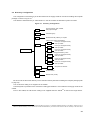
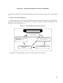
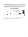
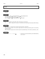
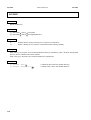
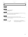
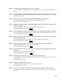
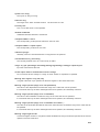
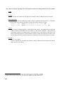
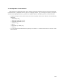
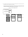
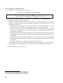
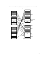
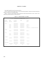
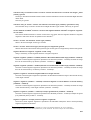
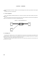
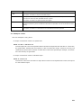
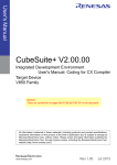
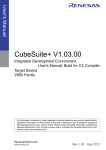
CHAPTER 1 OVERVIEW OF OPERATIONS
Volume 2 describes how to operate these compiler packages from the Project Manager and the VSH (shell
function).
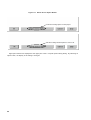
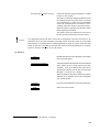
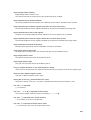
When using the CA to generate application load modules (i.e., compile/assemble source files, link object files,
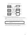
and create ROM-storing object file), there are two methods (shown in Figure 1-1): operating from the Project
Manager as part of an integrated environment or operating from the VSH’s command line interface.
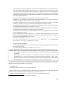
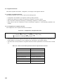
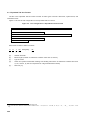
Figure 1-1. Outline of CA Package Operations
Windows
Project Manager
VSH
Specify options for
ca/as/ld/romp
Stand-alone activation of
ca/as/ld/romp
(option specification)
MAKE
for Project Manager
Stand-alone activation of
ar/dis/dump/hx
(option specification)
VMAKE
ca/as/ld/romp activation
Activation of all commands
Chapter 2 describes how to operate the compiler package from the Project Manager.
Chapter 3 describes the functions of VSH and how to operate the compiler package from the command line
interface of VSH, and Chapter 4 describes the functions and operations of the make utility VMAKE that runs on
VSH.
For details of CA command functions, options, etc., see the command-specific descriptions in Volume 3 and
later volumes.
32
CHAPTER 2 OPERATIONS USING THE PROJECT MANAGER
This chapter describes the use of the Project Manager to specify CA command options and to generate make
files.
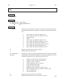
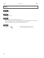
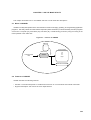
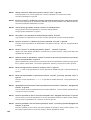
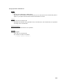
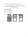
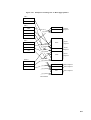
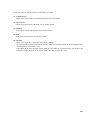
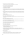
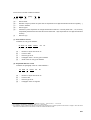
2.1 What is the Project Manager?
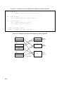
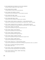
The Project Manager is a control software program that helps Windows-based programs run more efficiently,
and enables various operations—from editing a source program to compiling, executing, and debugging—to be
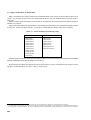
performed in a series (see Figure 2-1).
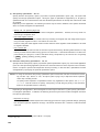
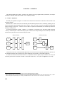
Figure 2-1. Project Manager and Development Tools
Project Manager
Project settings
Option settings for compiling
Editor setting
Additional source files
Reference and edit
source files
Build (make) project
Activate debugger
For details of the Project Manager, refer to the “Project Manager User’s Manual.”
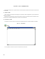
33
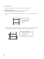
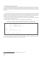
2.2 Activation of Project Manager
To activate the Project Manager, use the <<Project Manager>> icon that was registered when this compiler
package was installed.
Figure 2-2. Window for Activation of Project Manager
34
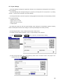
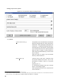
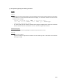
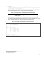
2.3 Project Settings
The Project Manager manages the application modules to be developed and development environments in
units of “projects”.
The Project Manager also manages settings for a project by recording them into a “project file”. By “setting
a project”, “a project file is generated” by Project Manager.
The settings listed below, which are required for creating application load modules, are automatically recorded
in the Project Manager.
• Required source files
• Target device to be used
• Editor and tools to be used
• Compile option
By opening the project file with the Project Manager, these settings are automatically repeated, enabling
restart of development with the same settings as when Project Manager was ended previously.
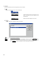
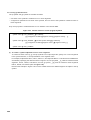
The following describes a newly created sample project entitled “test4”.
For details of project-related operations, refer to “Project Manager User’s Manual”.
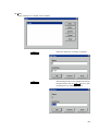
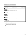
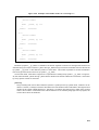
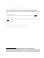
(1) Click New
Ctrl+N in the
Project
menu to open the <<Project Setup>> dialog.
(2) Set the project file name, title, project directory, series name, and device name for the project to be
created, then click the
OK
button.
35
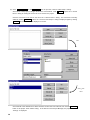
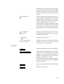
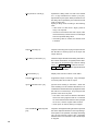
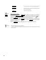
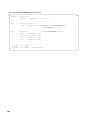
(3) Click
Source Files...
in the
Project
menu to open the <<Source Files Setup>> dialog.
Since this is a new project, nothing is shown in the source file list. Click
Add...
to open the << Source
Files>> dialog for setting the source file to be used for the project.
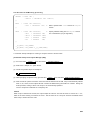
Click the source file to be used on the list of the <<Source Files>> dialog. The source file is actually
added by clicking
11Close
Add
. When the <<Source Files Setup>> dialog is displayed again by clicking
, the added file will be displayed on the list.
"Add"
Select + "Add"
↓
"Close"
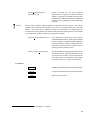
Check that all of the desired source files have been set from the source file list, then click the
OK
button to set project “test4” before exiting. In the title bar of the Project Manager, the project file name
“test4.prj” is displayed.
36
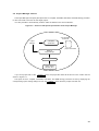
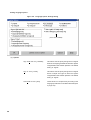
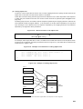
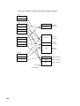
2.4 Project Manager and CA
The Project Manager can specify the options of the C compiler, assembler, link editor, and ROM-storing processor
for the source file to be used for the target project.
It is also possible to automatically create a make file based on the above selection.
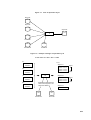
Figure 2-3. Outline of CA Option Specification from Project Manager
Auto generation
of make file
Project
Manager
… ……
… ……
… ……
CA option
specification
project-name .MAK
MAKE for
Project Manager
CA command activation
Object creation
file-name .OUT
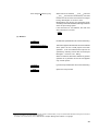
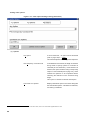
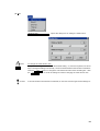
If you set a project file via the
Project
menu, the project file name will be shown in the “Titles” area as
shown in Figure 2-4.
The option of the C compiler, assembler, link editor, and ROM-storing processor are set by displaying the
corresponding option setting dialog box from the
Option
menu after the project has been set.
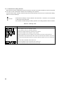
37
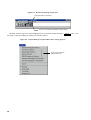
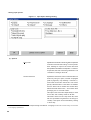
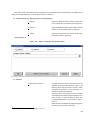
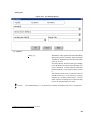
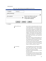
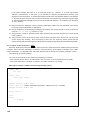
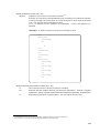
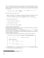
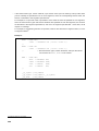
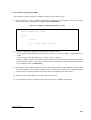
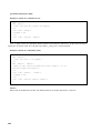
Figure 2-4. Window for Setting Project File
Project file name of set project
A menu of CA command is added via project setup
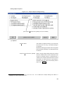
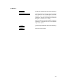
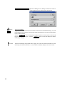
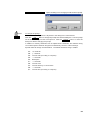
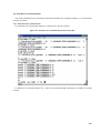
The items shown in Figure 2-5 will be displayed when you click the Project Manager’s
Option
this menu to open the dialogs for setting CA command options.
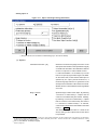
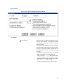
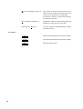
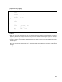
Figure 2-5. Project Manager’s Option Menu (after setting project)
To open command option
setting dialog of CA
38
menu. Use
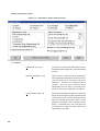
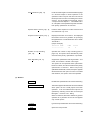
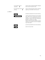
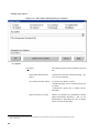
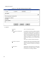
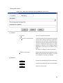
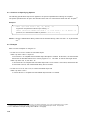
2.5 Dialogs for Setting CA Command Options
This section explains each dialog that sets the command option of the CA for the source file of the target
project.
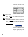
[Cautions]
• The option names used to activate commands from the VSH command line are displayed in square brackets
“[ ]”.
• For details of the various command functions, see the command-specific descriptions in Volume 3 and later
volumes.
• Volume 3 and later volumes contain lists of options for the various commands, including some options that
are not shown in the dialogs. These include options that do not have to be activated from the Project
Manager and options that cannot be specified from the Project Manager because they are fixed (refer to
page 29 for work directory description).
For example, the device specification “-cpu” that is in the option list for the ca and as commands is not
included since the device specification is already made when setting a project via the Project Manager.
• Debugger options (such as -g of ca and as) are not included in the option dialog described in the next
Option
section. With the
menu, the debug mode can be switched. Checking the
Debug
on the menu
sets the debug mode and not checking sets the non-debug mode. The default setting is debug mode.
2.5.1 Setting compiler options
The C compiler option setting dialog box for the C source file can be displayed by performing either of the
following operations after a project has been set with the Project Manager.
• Click the
Option
menu
→ Click Compiler Options...
• Click the
Option
menu
→ Click Source List
→ Click the source file for which options are to be set
→ Click the
Options...
button
The former is the setting for the C source file for the all target projects and the latter is the individual setting
for that C source file1. When source file-specific settings are made, overall option settings become invalid for the
particular source file.
If the
Delete Source Option
button is clicked on the setting dialog of each source, the option set for
each source file is deleted, and the option for the all projects set by the former method becomes valid.
1
“*” mark is appended to the file that is set to the individual option setting in <<Source List>>.
39
Figure 2-6. Delete Source Option Button
Invalid when setting options of entire project
Valid when setting individual options in Source List
Eight option buttons are displayed at the upper part of the C compiler option setting dialog. By selecting an
option button, the display of the dialog is changed.
40
(1) Option buttons for displaying option setting dialogs
1 Input
Opens the dialog box that is used to set the options
related to input to the C compiler (refer to page
42).
2 Preprocessor
Opens the dialog box that is used to set preprocessor-related options (refer to page 44).
3 Language
Opens the dialog box that is used to switch language
specifications (refer to page 46).
4 Optimization
Opens the dialog box that is used to set the
optimization level and type (refer to page 48).
5 Output 1
Opens the dialog box that is used to make output
object-related settings such as data allocation to
.sdata/.sbss sections and kanji code specifications
of the target (refer to page 50).
6 Output 2
Opens the dialog box that is used to make output
object-related settings such as register mode and
ROM-storing object creation specification (refer
to page 53).
7 Message
Opens the dialog box that is used to set the level
and item of warning message to be output (refer
to page 56).
0 Others
Opens the dialog box that is used to set the other
parameters (refer to page 58).
41
◊ Setting input options ◊
Figure 2-7. Input Option Settings Dialog
(1) Options
Kanji Code
Specifies the character code to be used for Japanese
comments and character strings2 in the input file.
Error message is output if the codes other than
the specified code exists in the input file. If <<None>>
is specified, the code cannot be guaranteed. The
<<Default>> setting is Shift JIS.
Section Data File
Specifies a section file name to allocate data to a
section by using an option, instead of #pragma
(refer to page 397). By checking <<Use File >>,
a file name can be set in the text box. Be sure to
specify a file name when <<Use File>> is checked.
Since a section file is divided into several files,
delimit each file names with “;” from others when
specifying two or more file names.
This option cannot be set independently for each
source file, and is always used for all files.
This area is in the form of a drop-down list, and a
file once specified is registered to the list (up to
10 files). This option can be selected by clicking
or arrow key.
2
Refer to the section of the V800 Series C Compiler Package User's Manual - C Language that describes character strings and comments
in the language specifications.
42
(2) Buttons
OK
Delete Source Option
Enables the specified items and closes the dialog.
This button appears dimmed and cannot be selected
when options for the overall project have been
specified. It can be selected when options are
specified by selecting source files via the Project
Manager’s <<Source List>> dialog.
When it is selected, this button deletes any options
specified for a particular source file and applies
only overall options.
Cancel
Help
Ignores the specified items and closes the dialog.
Opens the Help window.
43
◊ Setting pre-processor options ◊
Figure 2-8. Pre-processor Option Settings Dialog
(1) Options
Include Search Path [-I]
This specifies one or more directories to be searched
before the standard directory when searching for
header files. When specifying several paths, use
a semicolon “;” to separate the path specifications.
This area uses the “drop-down list” type of display
to list all directories that have been specified at
least once (up to 10 paths). To select a directory,
either click on the desired directory or use the arrow
keys to select it.
When this option is omitted, only the standard
directory3 will be searched 4.
Define Macro [-D]
Uses the “macro_name name = definition_value
def” format to define macro names. If the “= def”
specification is omitted, a value of 1 is assumed
as “ def”.
(Example) test = 2
It is assumed that “#define name def” is entered
before a C-language program.
When specifying several macros, separate them
with a semicolon “;”.
3
4
The standard directory is the installation directory (\incxxx).
In the format that encloses a file name with ‘"’, the directory where the source file exists is searched first. For the details of file search of
header file loading, refer to V800 Series C Compiler Package User’s Manual - C Language.
44
This area uses the “drop-down list” type of display
to list all macros that have been specified at least
once (up to 10 macros). To select a macro, either
click the desired macro or use the arrow keys to
select it.
Undefine Macro [-U]
Use this to specify the macro name name to be
rendered invalid. It is assumed that “#undef name”
is entered before a C-language source program.
When specifying several macros to be rendered
invalid, separate them with a semicolon “;”.
This area uses the “drop-down list” type of display
to list all macros that have been rendered invalid
(up to 10 macros). To select a macro, either click
the desired macro or use the arrow keys to select
it.
Limit of Number of
Specifies the upper limit of the number of macro
Macro [-Xm]
identifiers with a decimal number of up to 32767.
The default value is 2047.
Use Trigraph [-t]
Replaces the trigraph series.
Use C++ Style Comment
[-Xcxxcom]
text from “//” to the end of the line to be handled
In addition to ordinary comments, this allows any
as comments (C++ comment style).
(2) Buttons
OK
Delete Source Option
Enables the specified items and closes the dialog.
This button appears dimmed and cannot be selected
when options for the overall project have been
specified. It can be selected when options are
specified by selecting source files via the Project
Manager’s <<Source List>> dialog.
When it is selected, this button deletes any options
specified for a particular source file and applies
only overall options.
Cancel
Help
Ignores the specified items and closes the dialog.
Opens the Help window.
45
◊ Setting language options ◊
Figure 2-9. Language Option Settings Dialog
(In the case of CA850)
(1) Options
Sign of Bit field ‘int’ [-Xbitfield]
This area is used to specify the signed or unsigned
status of an integer type bit field for which the signed/
unsigned status has not been specified. The default
setting is “signed”.
Sign of ‘char’ [-Xchar]
This area is used to specify the signed or unsigned
status of simple char type for which the signed/
unsigned status has not been specified. The default
setting is “signed”.
Strict ANSI C Rule [-ansi]
Check this box to compile strictly according to the
language specification in the ANSI standards (refer
to page 155).
46
Strict Integer Extension [-Xe]
When this box is checked, _ _ _ mul/_ _ _ mulu and
___div/___divu from the runtime library5 are used
instead of mulh and divh instructions for integers
having data lengths of 16 bits or less.
Multiplication and division are performed strictly
according to the ANSI standards, although this slows
down the processing speed.
If this check box is not selected, the mulh and
divh instructions are used.
* V850
(2) Buttons
OK
Delete Source Option
Enables the specified items and closes the dialog.
This button appears dimmed and cannot be selected
when options for the overall project have been
specified. It can be selected when options are
specified by selecting source files via the Project
Manager's <<Source List>> dialog.
When it is selected, this button deletes any options
specified for a particular source file and applies
only overall options.
Cancel
Help
5
Ignores the specified items and closes the dialog.
Opens the Help window.
The runtime library in the CA850 is provided as this compiler’s standard library in order to fulfill the ANSI standards with regard to instructions
that are not included in the V850 Family architecture.
For details of the runtime library, refer to V800 Series C Compiler Package User’s Manual - C Language.
47
◊ Setting optimization options ◊
Figure 2-10. Optimization Option Settings Dialog
(1) Options
Optimization Level [-O]
Use this area to specify the optimization level and
related items (refer to page 156). The default setting
is level 1.
Optional Optimization [-Ol]
Check this box to perform optional optimization.
This emphasizes optimization measures such as
code scheduling and redundant instruction
elimination. However, the compiling speed is
reduced.
This box can be selected where
optimization level 2 or above, or execution timepriority or size-priority optimization is selected.
Code Threshold [-Wp, -N]
Limits the intermediate language size of a function
subject to inline expansion to the specified number
of bytes and does not execute inline expansion a
function exceeding this number of bytes. For the
guideline of the length, refer to “Output Function
Report”. The default size is 128. This option can
be specified only when execution time-priority
optimization is specified.
48
Stack Threshold [-Wp, -G]
Limits the stack length in the intermediate language
of a function subject to inline expansion to the
specified number of bytes and does not execute
inline expansion a function exceeding this number
of bytes. For the guideline of the length, refer to
<<Output Function Report>>. The default size is
32. This option can be specified only when execution
time-priority optimization is executed.
Expand Static Function [-Wp, -S]
Performs inline expansion of static functions that
are referenced only once.
Output Function Report [-Wp, -I]
Displays information on functions. The displayed
information serves as a guideline for specifying
the upper limits of <<Code Threshold>> and <<Stack
Threshold>>.
(Output example)
function name
code
stack
-------------
15
4
Number of Loop Unrolling
Specifies the number of loop unrolling (refer to
[-Wo, -Ol]
page 173). This option can be selected only when
execution time-priority optimization is specified.
Pack Alignment [-Wi, -P]
Suppresses optimization that aligns labels. As a
result, this enables a smaller code length.
This option can be specified where optimization
level is 2 or above, and when execution time-priority
optimization is selected.
When size-priority
optimization is selected, however, this option appears
dimmed because this option function is included
and therefore, this option cannot be specified.
(2) Buttons
OK
Delete Source Option
Enables the specified items and closes the dialog.
This button appears dimmed and cannot be selected
when options for the overall project have been
specified. It can be selected when options are
specified by selecting source files via the Project
Manager's <<Source List>> dialog.
When it is selected, this button deletes any options
specified for a particular source file and applies
only overall options.
Cancel
Help
Ignores the specified items and closes the dialog.
Opens the Help window.
49
◊ Setting output 1 options ◊
Figure 2-11. Output 1 Option Settings Dialog
(1) Options
Frequency Information File
Clicking <<Create File>> creates a frequency
information file that is necessary for creating a
section file that allocates sections by using the
section file generator (sf) (refer to page 397). If
<<Specify File>> is not clicked, the frequency
information file is created under the name with .c
of the source file changed to .sec. If <<Specify
File>> is clicked, a file name can be specified in
the text box. In this case, be sure to specify a file
name. This area uses the "drop-down list" type
of display to list all files that have been specified
at least once (up to 10 files). Either click the desired
file or use the arrow keys to select it.
* V850
CAUTIONS
When specifying an information file name for each of two or more source files, do not specify
a file name with an option that is related to all the projects, but specify a file name by using
an option that is related to each source file.
This option also outputs the frequency information on the variables in the C source file. It
does nothing to the assembler source file.
50
sdata/sbss Allocation [-G]
Use this area to specify the length of data allocated
to the .sdata/.sbss section.
If all data allocations are cancelled, input to the
text box for specifying the data length is enabled.
Data of the specified size (in bytes) or less is allocated
to the .sdata or .sbss section. However, data for
which the .sdata or .sbss section is specified by
the #pragma section directive6 or section file (refer
to page 408) is allocated to the .sdata or .sbss
section regardless of its size.
Kanji Code of Target
Japanese character strings are converted into
specified codes and output7. This conversion is
convenient when converting Kanji codes that were
used in application development, in the target. Codes
are not converted when <<None>> or <<Default>>
is specified.
The comment output by the specification of [Output
Source Comment] is not converted in spite of this
option.
CAUTIONS
If code other than the default (shift JIS) are used in the input file whose code is to be
converted by the specification of [Kanji Code of Target], specify the code being used with
[Kanji Code] of the [Input] option.
Input file
EUC
[Input]
Kanji Code
EUC
Output file
Shift JIS
[Output 1]
Kanji Code of Target
Shift JIS
Unless specified, the code is not converted because the input default is recognized as shift
JIS.
Output Assemble List [-a]
The assembly list is output to a file whose extension
.c is changed to .v (refer to page 208).
6
7
Refer to the data section allocation in the V800 Series C Compiler Package User’s Manual - C Language.
Refer to the section of the V800 Series C Compiler Package User’s Manual - C Language that describes character strings and comments
in the language specifications.
51
Output Source Comment [-Xc]
Outputs a C-language source program to the
assembler source file to be output as comments.
This option can be specified only when [Output
Assemble List] is specified.
The comments that are output, however, are only
for reference and may not strictly correspond to
the codes. For example, the output position of
the global variables, local variables, and function
declaration may be shifted. In addition, the codes
may be deleted and only comments may remain
because of optimization.
Use Performance Checker [-Xpc]
This box cannot be selected at present.
Output Information for Analyzer
This box cannot be selected at present.
[-Xaz]
(2) Buttons
OK
Delete Source Option
Enables the specified items and closes the dialog.
This button appears dimmed and cannot be selected
when options for the overall project have been
specified. It can be selected when options are
specified by selecting source files via the Project
Manager’s <<Source List>> dialog.
When it is selected, this button deletes any options
specified for a particular source file and applies
only overall options.
Cancel
Help
52
Ignores the specified items and closes the dialog.
Opens the Help window.
◊ Setting output 2 options ◊
Figure 2-12. Output 2 Option Settings Dialog
(Add "Output of bdld Instruction [-Xbdld]" in the case of CA830)
(1) Options
Register Mode
The number of registers used by ca can be set by
the user as 26 or 22 only8. The default setting is
32 registers.
Because the setting by this option is also recognized
by the link editor, the library in an appropriate mode
is referred.
Output of bdld Instruction [-Xbdld]
When a 16-byte or larger static structure or external
structure variable value, which is allocated to the
section for external memory, is substituted as a
variable to the .sidata section allocated to internal
data RAM, the bdld instruction is generated in
assembly language using ca and output (refer to
page 166). * V830
8
This switches the register mode of the software register bank function. Refer to V800 Series C Compiler Package User’s Manual - C
Language for the software register bank function.
53
Inline Expansion of strcpy () [-Xi]
The function call of the strcpy() function is converted
into block transfer. This causes the object execution
speed to become higher, but the code size also
becomes larger.
However, conversion is performed only when the
second argument of strcpy () is a character string.
Moreover, the first argument must be 4-byte aligned
by the program (as the second argument is a
character string, the C compiler has already aligned
the second argument).
Change Jump Code of Interruption This option changes the instruction for branching
[-Xj]
to the interrupt function from the jr instruction to
the jmp instruction (refer to page 157).
When the function itself is in the range where
branching from the jr instruction is not possible
and ld outputs an error, recompilation is performed
using this option.
Use Mask Register [-Xmask_reg]
This option sets the use of the mask register function9.
Specifying this option automatically sets the check
during linking by link editor, and an error results
if a mask-register-enabled object and mask-registerdisabled object coexist.
This option cannot be selected separately for each
source file setting. This option is always set as
the overall option.
CAUTIONS
Even in applications where both the C source file and assembler source file are used, or in
applications where only the assembler source file is used, [Use Mask Register] must be
specified by both the C compiler option and assembler option.
Use Old Style Function Call
[-Xold_fcall]
This option outputs the codes that comply with
the old-version call specifications of the C compiler.
By specifying this option, the specification of [Use
Mask Register] becomes invalid. The old style
library is referenced automatically in library
references by a link editor.
This option cannot be selected separately for each
source file setting. This option is always set as
the overall option. * V850
This option cannot be specified when using the
V850E for the target device.
CAUTIONS
If one wishes to use the old style call specifications, this option must be specified with C
compiler option, even in application using both C source files and assembler source files,
or only assembler source files, in order to reference the old style library.
9
Refer to V800 Series C Compiler Package User’s Manual - C Language.
54
Create Object for ROM [-Xr]
This option is required when creating an object to
be stored in ROM. Following link processing, the
processor for ROM writing is started. The generated
object file (.out file) contains ROM writing information.
The label of the first argument of __rcopy should
be designed so as to indicate the first address10
after the .text section end in the object. In addition,
this option indicates that rompcrt.o file and libr.a
file are to be linked with ld11. This option cannot
be selected separately for each source file setting.
This option is always set as the overall option.
Use Word Switch Table
This option creates a branch table for the case
[-Xword_switch]
label in the switch statement in 4 bytes per label.
Specify this option if compile errors due to long
switch statements occur.
If this option is not specified, the branch table is
generated in 2 bytes.
(2) Buttons
OK
Delete Source Option
Enables the specified items and closes the dialog.
This button appears dimmed and cannot be selected
when options for the overall project have been
specified. It can be selected when options are
specified by selecting source files via the Project
Manager’s << Source List>> dialog.
When it is selected, this button deletes any options
specified for a particular source file and applies
only overall options.
Cancel
Help
10
11
Ignores the specified items and closes the dialog.
Opens the Help window.
Aligned with 4-byte alignment condition
Refer to page 386.
55
◊ Setting message options ◊
Figure 2-13. Message Option Settings Dialog
(1) Options
Warning Level
No Output [-w]:
Level 1:
Level 2 [-w2]:
Use this area to set the level of warning messages
to be output.
Suppress warning messages
Output ordinary warning messages (default)
Output detailed warning messages
Verbose Mode [-v]
Displays execution status in C compiler.
Individual Warnings
Specifies output or suppression of output of a warning
message of each item, regardless of the level. The
warning message is output when the check box
in this area is checked. The warning message is
not output when the check box is displayed in gray.
Bit Field Alignment [-wbitfield_align] Outputs a warning message if the member of a
bit field is allocated from the next boundary because
it exceeds the boundary of alignment condition.
56
Call of Not Declared Function
[-wcallnodecl]
Outputs a warning message if a function not declared
is called.
Use of Non PIC [-wnopic]
When this box is selected, a warning is output upon
initialization of a pointer type external variable which
uses a variable’s address that is not an automatic
variable or which uses a function’s address.
Unrecognized ‘#pragma’
[-wpragma]
Outputs a warning message if description of #pragma
that cannot be executed is found.
Non White Space before Sharp
[-wsharp]
Outputs a warning message in respect to # character
appearing in the middle of the source line.
(2) Buttons
OK
Delete Source Option
Enables the specified items and closes the dialog.
This button appears dimmed and cannot be selected
when options for the overall project have been
specified. It can be selected when options are
specified by selecting source files via the Project
Manager’s <<Source List>> dialog.
When it is selected, this button deletes any options
specified for a particular source file and applies
only overall options.
Cancel
Help
Ignores the specified items and closes the dialog.
Opens the Help window.
57
◊ Setting other options ◊
Figure 2-14. Other Option Settings Dialog (C Compiler)
(1) Options
Any Option
The following options can be specified in the text
box.
Optimization Enhancement
To perform the data flow analysis precisely, “-Wi,
Option
-O4” can be described12.
CPU Fault Prevention Option
To prevent CPU faults13, options:
“-Xnoabcond” (page 157) or “-Xnopldsr” (page 157)
in CA830
“-Xv850patch” (page 157) in CA850 can be
described.
Options Common to Family
Options are passed to the assembler, because
objects are shared in the family14. “-Wa, -cn” can
be described. In the CA850, the “-Wa, -cnv850e”
option can also be described.
12
13
14
Refer to pages 162 and 173.
To check whether the fault that has occurred applies to the CPU used, refer to the documents supplied with the CPU.
Refer to page 205.
58
Use Temporary Command File
In the Windows environment, the length of character
strings used to specify options for command is
restricted (to 126 characters). If this check box is
selected, the option character string is temporarily
output to a command file (refer to page 161), which
enables the operation to be completed without
observing the restriction on the character string
length.
This option is checked as default assumption.
Command Line Options
Displays C compiler options set in each dialog with
the command line options. This area is for reference,
and writing is disabled.
(2) Buttons
OK
Delete Source Option
Enables the specified items and closes the dialog.
This button appears dimmed and cannot be selected
when options for the overall project have been
specified. It can be selected when options are
specified by selecting source files via the Project
Manager’s <<Source List>> dialog.
When it is selected, this button deletes any options
specified for a particular source file and applies
only overall options.
Cancel
Help
Ignores the specified items and closes the dialog.
Opens the Help window.
59
2.5.2 Setting assembler options
The assembler option setting dialog box for the assembler source file can be displayed by performing either
of the following operations after a project has been set with the Project Manager.
• Click the
Option
menu
→ Click Assembler Options...
• Click the
Option
menu
→ Click Source List
→ Click the source file for which options are to be set
→ Click the
Options...
button
The former is the setting for the assembler source file for the all target projects and the latter is the individual
setting for that source file15. When source file-specific settings are made, overall option settings become invalid
for the particular source file.
If the
Delete Source Option
button is clicked on the setting dialog of each source, the option set for each
source file is deleted, and the option for all the projects set by the former method becomes valid.
Figure 2-15. Delete Source Option Button
Invalid when setting options of entire project
Valid when setting individual options in Source List
15
“*” mark is appended to the file that is set to the individual option setting in <<Source List>>.
60
Three option buttons are displayed at the upper part of the assembler option setting dialog. The display of the
dialog is changed depending on which option button is selected.
(1) Option buttons for displaying option setting dialogs
1 Option 1
Opens the dialog box that is used to set the path
of the include file in assembler (refer to page 61).
2 Option 2
Opens the dialog box that is used to set the ordinary
options of the assembler (refer to page 63).
0 Others
Opens the dialog box that is used to set the other
parameters (refer to page 66).
◊ Setting option 1 ◊
Figure 2-16. Option 1 Settings Dialog (Assembler)
(1) Options
Include Search Path [-I]
Specifies a directory that is searched for the file
specified by the file input directive16 prior to the
directory where the source file is placed. When
specifying several paths, use a semicolon ";" to
separate the path specifications.
This area uses a "drop-down list" type of display
to list all directories that have been specified once
(up to 10 files). To select a directory, either click
on the desired directory or use the arrow keys to
select it.
When this option is omitted, only the directory where
the source file is placed is searched.
16
Refer to User’s Manual - Assembly Language of each family.
61
(2) Buttons
OK
Delete Source Option
Enables the specified items and closes the dialog.
This button appears dimmed and cannot be selected
when options for the overall project have been
specified. It can be selected when options are
specified by selecting source files via the Project
Manager’s << Source List>> dialog.
When it is selected, this button deletes any options
specified for a particular source file and applies
only overall options.
Cancel
Help
62
Ignores the specified items and closes the dialog.
Opens the Help window.
◊ Setting option 2 ◊
Figure 2-17. Option 2 Settings Dialog (Assembler)
( "Unique to Device" and "Common to V830 Family[-cn]" in the case of CA830)
(1) Options
sdata/sbss Allocation [-G]
Generates a machine language instruction on the
assumption that all data of the specified size (byte)
or smaller are allocated to the sdata/sbss-attribute
section in response to external label access17.
If <<Allocate All Data>> is cancelled, input to the
text box for specifying the data length is enabled.
On the other hand, for data whose sdata option is
specified by the .option pseudo-instruction 18, a
machine language instruction is generated on the
assumption that the data is allocated to the sdataattribute section or sbss-attribute section regardless
of its size.
Magic Number
Specifies magic number of the object. By selecting
<<Common to V850 Family>>, objects that are
common in the V850 Family are created. Similarly,
by selecting <<Common to V830 Family>>, objects
that are common in the V830 Family are created.
If <<Common to V850E Family>> is selected,
common items are limited to the V850E in the V850
Family19. * V850
The default is fixed for the device. If fixed for the
device, linking to other objects fixed to the device
is impossible.
17
18
19
If as is activated from ca at the VSH command line, the -Gnum option specified for ca will be passed even if this option is not specified for
as, but only the settings made via this dialog are valid for assembly source files. This does not affect the <<sdata/sbss Allocation>> setting
made via the compiler option settings dialog.
63
Refer to User’s Manual - Assembly Language.
Refer to page 202.
Output Assemble List [-a -l]
Outputs the assemble list. Unlike the “-a -l”
specification for “as” in the VSH command line
base, processing of the “-a” in the ca command is
executed (refer to page 157). In other words, the
assemble list is output to a file whose extension
is changed to “.v”.
Do Optimization [-O]
Executes optimization, which rearranges instructions
to avoid register and flag hazards. Optimization
by assembler is not compatible with the debugger20.
When the debug mode (-g option) is specified in
the Project Manager [Option] → [Debug]
specification; the debug mode is ignored if there
is a debug information section in the source file.
Optimization is ignored and the debug mode is
valid if there is no debug information section.
Verbose Mode [-v]
Suppress Warning [-w]
This displays execution status of assembler.
Warning messages are not output when r1 has
been specified as the source register or destination
register, when r20 or r21 has been specified as a
destination register when the mask register function
has been used, when r0 has been specified as
the destination register, or when r30 has been
specified as the destination register for the mul/
mulu/div/divu instructions in V830 Family.
Use Mask Register [-m]
Creates an object file having information that the
mask register function21 is used. When <<Use
New Style Function Call>> is specified, this option
can be specified. It is valid when an assembler
source file created with the old version of the C
compiler is used.
This option cannot be selected for each source
file and is always selected for all source files.
CAUTIONS
In an application where both the C source file and assembler source file are used or in an
application where only the assembler source file is used to specify checking during linking,
[Use Mask Register] must be specified by both the C compiler option and assembler option.
20
21
Refer to -g option on page 202.
Refer to V800 Series C Compiler Package User’s Manual - C Language.
64
Use New Style Function Call [-f]
Creates an object file having information of “calling
function of new version”.
This option is valid when using an assembler source
file created with the old version of the C compiler
of the V850 Family, or when using the assembler
source file created with the old version of the C
compiler of the V810 Family in the V830 Family 22.
When this option is specified, specification of [Use
Mask Register] is available.
This option cannot be selected for each source
file and is always selected for all source files.
CAUTIONS
In an application where both the C source file and assembler source file are used or in an
application where only the assembler source file is used, and if this option is not specified
and assembly is executed with the calling specifications of the old version when the V850
Family is used, the “Use Old Style Function Call” option must be specified by the C compiler
option to reference the library of the old version.
(2) Buttons
OK
Enables the option that was selected via the dialog
and closes the dialog.
Delete Source Option
This button appears dimmed and cannot be selected
when options for the overall project have been
specified. It can be selected when options are
specified by selecting source files via the Project
Manager’s <<Source List>> dialog.
When it is selected, this button deletes any options
specified for a particular source file and applies
only overall options.
Cancel
Help
22
Ignores the specified items and closes the dialog.
Opens the Help window.
Refer to V800 Series C Compiler Package User’s Manual - C Language.
65
◊ Setting other options ◊
Figure 2-18. Other Option Settings Dialog (Assembler)
(1) Options
Any Option
To avoid CPU fault, “-P” option can be described
(refer to page 206)23. * V850
The other descriptions are not supported at present.
Use Temporary Command File
In the Windows environment, the length of character
strings used to specify options for command is
restricted (to 126 characters). If this check box is
selected, the option character string is temporarily
output to a command file (refer to page 161), which
enables the operation to be completed without
observing the restriction on the character string
length.
This option is checked as default assumption.
Command Line Options
Displays assembler options set in each dialog with
the command line options. This area is for reference,
and writing is disabled.
23
For whether the fault that has occurred is of the CPU used, refer to the documents supplied with the CPU.
66
(2) Buttons
OK
Delete Source Option
Enables the specified items and closes the dialog.
This button appears dimmed and cannot be selected
when options for the overall project have been
specified. It can be selected when options are
specified by selecting source files via the Project
Manager’s <<Source List>> dialog.
When it is selected, this button deletes any options
specified for a particular source file and applies
only overall options.
Cancel
Help
Ignores the specified items and closes the dialog.
Opens the Help window.
67
2.5.3 Setting link editor options
The link editor option setting dialog box can be displayed by performing the following operation after a project
has been set with the Project Manager.
• Click the
Option
menu
→ Click Linker Options...
Since the link editor needs to be activated only once per project, there are no file-specific settings.
The names of executable object files that can be output by the link editor is the first filename (minus the
extension) shown in the <<Source List>> dialog, to which the extension “.OUT” is added. The output filename
cannot be specified (there is no specification method that corresponds to the “-o” specification to activate from
the VSH command line).
Three option buttons are displayed at the upper part of the link editor option setting dialog. By selecting an
option button, the display of dialog is changed.
(1) Option buttons for displaying option setting dialogs
1 File
Opens the dialog box that is used to set the options
related to the files to be referenced or linked by
the link editor (refer to page 69).
2 Option
Opens the dialog box that is used to set the ordinary
options of the link editor (refer to page 71).
0 Others
Opens the dialog box that is used to set the other
parameters (refer to page 74).
68
◊ Setting files ◊
Figure 2-19. File Settings Dialog
(1) Options
Library [-l]
Specifies the “string” portion of the archive file (library
file) libstring.a to be accessed. When specifying
several files, separate each name with a semicolon
(such as “m;usr”).
This area uses the “drop-down list” type of display
to list all libraries that have been specified once
(up to 10 libraries). To select a library, either click
the desired library or use the arrow keys to select
it.
The specified archive file is searched from the
standard directory 24 of the directory or library
specified by <<Library Search Path>>. The link
editor outputs no message and continues linking
even if the specified file is not found.
CAUTIONS
24
The standard library (“c”) is referenced as default assumption even if it is not specified.
Install directory \libxxx and install directory \libxxx\r32.
69
Library Search Path [-L]
Specifies the directory where the archive file (library
file) to be accessed is stored. When specifying
several libraries, separate each name with a
semicolon “;”.
This area uses the “drop-down list” type of display
to list all directories that have been specified once
(up to 10 directories). To select a directory, either
click the desired directory or use the arrow keys
to select it.
If a directory is specified by this option, the library
is searched from the specified directory before the
standard directory of the library. If two or more
libraries are specified, the library is searched in
the sequence in which they have been specified
in the text box.
Link Directive File [-D]
This specifies the link directive file to be accessed
(refer to page 254). This area uses the “dropdown list” type of display to list all directive files
that have been specified once (up to 10 files). Either
click the desired directive file or use the arrow
keys to select it.
Startup File
This specifies the start-up module’s file25. When
creating a final object file via the build/rebuild function
(in other words, in cases other than when creating
a file whose target specification in building is “.o
file”), if this start-up file specification is omitted,
the supplied start-up module26 is linked.
This area uses the “drop-down list” type of display
to list all files that have been specified once (up
to 10 files). Either click the desired file or use the
arrow keys to select it.
CAUTIONS
If the path is not specified in the link directive file or start-up module, “project directory” that
is specified during project creation is searched. If the file locates in other directory path,
specify the absolute path name or relative path name from the project directory.
(2) Buttons
OK
Enables the specified items and closes the dialog.
Cancel
Ignores the specified items and closes the dialog.
Help
25
26
Refer to V800 Series C Compiler Package User’s Manual - C Language.
Install directory \libxxx\ rxx\crtN.o
70
Opens the Help window.
◊ Setting options ◊
Figure 2-20. Option Settings Dialog (Link Editor)
(1) Options
Entry Symbol [-e]
Use this text box to specify a symbol to be set as
the entry point address. If the specified symbol
is not found, the link editor outputs a message
and stops linking.
This area uses the “drop-down list” type of display
to list all symbol names that have been specified
once (up to 10 symbol names). Either click on
the desired symbol name or use the arrow keys
to select it.
If this option is not specified, the entry point address
value is determined by the following rules.
• Value of symbol _start if the symbol exists.
• The first address of the text-attribute section
allocated to the lowest part in the object file created
if symbol _start does not exist.
• 0 if the text-attribute section does not exist.
71
Filling Number of Hole [-f]
Specifies the filling value of a hole to be created
as a 4-digit hexadecimal number (2 bytes).
Specification by this option takes precedence over
the filling value specified by the link directive file
(refer to page 254).
Specify a filling value according to the following
rules.
• If the value is of less than 4 digits, prefix as
many 0 as required.
• If the size of the hole is less than 2 bytes, take
out the necessary number of the low-order digits
from the specified filling value.
• If the filling value is omitted, the default value
is 0x0000.
Output Link Map [-m]
Outputs a link map (refer to page 318) that shows
the allocation of memory space in the input and
output sections.
Strip Debug Information [-s]
Creates an object file without the debug information,
line number information, and global pointer table.
This option can be specified only in the non-debug
mode. If
Option
Debug
is selected from the
menu, this option appears dimmed
and cannot be specified.
Verbose Mode [-v]
Suppress Warning [-w]
Displays the execution status of link editor.
Suppresses output of warnings. Only messages
concerning fatal errors will be output.
Ignore Relocation Error [-E]
Ignores errors relating to relocation. When the
value resulting from an address calculation for an
undetermined external reference is judged as invalid,
that value is not entered (i.e. is ignored) and the
previous value is left in place.
• The value of the result of address calculation
which has been judged invalid is not entered
for unresolved external reference that is judged
as an error, and the original value remains.
• If this option is omitted, linking is stopped.
Check All Multi-Defined Symbol
Outputs a message describing all external symbols
[-M]
that have duplicate definitions and stops linkage.
If this option is not specified, a message describing
only the first external symbol with a duplicate
definition that is encountered is output and linkage
is stopped.
72
Ignore Undefined External
Ignores checking the size and sequence
Symbol Error [-t]
requirements for linkage of undefined external
symbols. If this option is omitted, the symbol size
and alignment condition are checked. If a difference
is found, a warning message is output and linking
continues.
CAUTIONS
The link editor supports multiple definition of undefined external symbols. The defined
multiple external symbols are allocated to the .sbss or .bss section after they have been
linked. If the symbol size or alignment condition of the symbols to be linked differ, the
maximum size of the symbols to be linked is used as the size and the least common multiple
of the alignment condition is used as the alignment condition.
Ignore External Symbol Error [-T]
This suppresses checking size when linking
undefined external symbols. If this option is omitted,
the size is checked. If a difference in size is detected,
a warning message is output and linking continues.
At this time, the symbol size of a file for which a
symbol is actually defined is valid.
Check Function Call Style [-fc]
Checks whether the calling specifications27 of the
old version and the calling specifications of the
new version do not exist in mix in all input object
files. If this option is not specified, only the object
file created from the C source file is checked.
(2) Buttons
OK
Enables the specified items and closes the dialog.
Cancel
Ignores the specified items and closes the dialog.
Help
27
Opens the Help window.
Refer to V800 Series C Compiler Package User’s Manual - C Language.
73
◊ Setting other options ◊
Figure 2-21. Other Option Settings Dialog (Link Editor)
(1) Options
Any Option
Use Temporary Command File
This is not supported at present.
In the Windows environment, the length of character
strings used to specify options for command is
restricted (to 126 characters). If this check box is
selected, the option character string is temporarily
output to a command file (refer to page 161), which
enables the operation to be completed without
observing the restriction on the character string
length.
This option is checked as default assumption.
Command Line Options
Displays link editor options (excluding library-related
options) set in each dialog with the command line
options. This area is for reference, and writing is
disabled.
Library Options
Displays library-related options set in the file option
dialog with the command line options. This area
is for reference, and writing is disabled.
74
(2) Buttons
OK
Enables the specified items and closes the dialog.
Cancel
Ignores the specified items and closes the dialog.
Help
Opens the Help window.
75
2.5.4 Setting ROM-storing processor options
The ROM-storing processor option setting dialog box can be displayed by performing the following operation
after a project has been set with the Project Manager.
• Click the
Option
menu
→ Click ROM Processor Options...
Since the ROM-storing processor needs to be activated only once per project, there are no file-specific settings.
The name of executable object file that can be output by the ROM-storing processor is the first filename
(minus the extension) shown in the <<Source List>> dialog, to which the extension “.OUT” is added, and is the
same object file name output by the link editor. The ROM-storing processor is started up by the Project Manager
only when <<Create Object for ROM>> has been specified as a C compiler option. At that time, the object file
output by the link editor is a temporary file which is deleted when the ROM-storing processor is terminated.
The output object file name cannot be specified (there is no specification method that corresponds to the “o” specification to activate from the VSH command line).
Two option buttons are displayed at the upper part of the ROM-storing processor option setting dialog. By
selecting an option button, the display of dialog is changed.
(1) Option buttons for displaying option setting dialogs
1 Option
Opens the dialog box that is used to set the ordinary
options of the ROM-storing processor (refer to page
77).
0 Other
Opens the dialog box that is used to set the other
parameters (refer to page 79).
76
◊ Setting options ◊
Figure 2-22. Option Settings Dialog (ROM-Storing Processor)
(1) Options
Packing Section [-p]
The contents of the specified section and the
corresponding address and size data are entered
in the rompsec section. If the specified section
does not exist in the object file, a message is output
and processing is stopped. If this option is omitted,
it is assumed that all sections that contain a data
attribute or sdata attribute have been specified.
In addition, for the CA830, the text-attribute section
for the interrupt allocated to on-chip instruction
RAM and the .itext section is also assumed as
being specified.
When several sections have been specified, use
a semicolon (;) to separate the specified sections.
The specified sections are entered to the rompsec
section in the order they were specified.
This area uses the “drop-down list” type of display
to list all sections that have been specified once
(up to 10 sections). Either click on the desired
section or use the arrow keys to select it.
Entry Label [-b]
The specified label value is used as the first address
of the created rompsec section. If the specified
label does not exist in an object file, a message
is output and processing is stopped.
If this option is omitted, it is assumed that __S_romp
has been specified.
This area uses the “drop-down list” type of display
to list all labels that have been specified once (up
to 10 labels). Either click on the desired label or
use the arrow keys to select it.
77
Delete ‘text’ Attribute Section [-d]
This creates an object file that contains only a
rompsec section, without entering a section that
contains a text attribute in the created file.
If this option is omitted, a section that contains a
text attribute is entered.
Ignore Address Repetition [-i]
A duplication check is not performed between the
addresses of input files and output files.
Output Memory Map [-m]
A memory map of the created object file is output
to standard output.
(2) Buttons
OK
Enables the specified items and closes the dialog.
Cancel
Ignores the specified items and closes the dialog.
Help
78
Opens the Help window.
◊ Setting other options ◊
Figure 2-23. Other Option Settings Dialog (ROM-Storing Processor)
(1) Options
Any Option
This is not supported at present.
Use Temporary Command File
In the Windows environment, the length of character
strings used to specify options for command is
restricted (to 126 characters). If this check box is
selected, the option character string is temporarily
output to a command file (refer to page 161), which
enables the operation to be completed without
observing the restriction on the character string
length.
This option is checked as default assumption.
Command Line Options
Displays ROM-storing processor options set in each
dialog with the command line options. This area
is for reference, and writing is disabled.
(2) Buttons
OK
Enables the specified items and closes the dialog.
Cancel
Ignores the specified items and closes the dialog.
Help
Opens the Help window.
79
2.6 Creating and Building Make Files
The Project Manager can be used to create make files that incorporate the options specified in each dialog
of the C compiler, assembler, link editor, or ROM-storing processor by a menu.
When build of the application load module is specified, the building starts after creating the make file automatically.
For details of the menu items or the build function, refer to Project Manager User’s Manual.
2.6.1 Using menu to create make files
The following operation will create a make file from a menu of the Project Manager.
• Click the
Project
menu
→ Click Make a Make File
Ctrl+M
If the information required for creating a make file has not been set, the menu item Make a Make File
Ctrl+M
appears dimmed and cannot be selected.
When Make a Make File
Ctrl+M has been selected, a make file is generated based on the option information
set via the CA command’s option dialog.
While the make file is being generated, the message “Generating make file” is displayed in the status bar, and
once the make file has been generated, the status bar message changes to “Make file generation completed.”
The filename of the generated make file is “projectname + .MAK”. In addition to the make file, another file
named “projectname + .SDB” is simultaneously generated for managing information related to the source file.
80
2.6.2 Auto generation of make file via build function
Make files can be automatically generated by executing “build” from the Project Manager. There are three
types of “build” specifications: “build”, “rebuild”, and “build specified target”.
(1) Build
Build can be selected via either of the following operations.
• Click the
Run
menu
→ Click Build
• Click the
Ctrl+B
button
When this build function is selected, a make file is generated in the same way as when
Make a Make File
Ctrl+M is selected. Depending on the make file generated by the build function,
C compiler, assembler, link editor, or ROM-storing processor is executed and an executable object file is
created as the make target.
A window <<PRJTMAKE>> displaying the build execution conditions and status is opened, and this is
where any error messages output by the CA command are displayed. The contents shown in this window
are output to a file in the project directory called “(projectname).PLG.”
To abort build, click the “!” mark button in the execution display window <<PRJTMAKE>>, or click the
Run
menu and
Stop Build
in the Project Manager.
81
(2) Rebuild
The rebuild function can be selected via the following operation.
• Click the
Run
menu
→ Click Rebuild
When the rebuild function is selected, a make file is generated and all objects that are make targets are
newly generated. This function is the same as the build function except that make files are generated
unconditionally, i.e., regardless of whether or not the source files and option settings have been changed.
82
(3) Build specified target
This function can be selected via the following operation.
• Click the
Run
menu
→ Click Build Target...
→ Click target for build using the displayed dialog.
→ Click
Build
When “build specified target” has been selected, a make file is generated and only the make target that
has been specified (among the several make targets) is newly generated. This function is the same as
the build function except that only the specified target is generated unconditionally.
83
CHAPTER 3 USE OF COMMAND SHELL
This chapter describes how to operate the VSH command shell and activate the VSH internal command and
CA command.
3.1 What is VSH?
VSH is a utility that is provided for activating the CA commands, which are applications, by the command line
interface on Windows.
Activate VSH on the Windows to open the VSH window, and the CA commands, internal commands of VSH,
and execution commands of Windows can be used on the command line.
3.2 Activation of VSH
To activate VSH, click the VSH icon twice that was registered when this compiler package was installed.
Figure 3-1. VSH Window
It is not possible to activate more than one VSH shell at the same time.
84
3.3 Function of VSH
VSH includes the following features.
• Enables command line editing
• Enables displays that can be scrolled vertically and horizontally
• Includes a history function to recall previous input
• Includes an alias function to assign aliases for command names
• Supports 31 types of internal commands (refer to page 102)
• Supports commands from MS-DOS applications that include Windows-type executable files and PIF (program
information files) as external commands
Note that although VSH is a shell like a command.com of MS-DOS, it is a Windows-based utility, which means
that MS-DOS commands cannot be activated directly from the VSH shell.
85
3.3.1 Command line editing function
When the VSH window is displayed, internal commands, execution commands of Windows, and CA commands
can be input via the command line interface at the blinking cursor position.
From the VSH window, ordinary character keys and several edit keys can be used for command line editing.
Table 3-1 lists the edit keys.
CAUTIONS
• Command line editing’s scope is limited to the client area. Therefore, it is not possible
to edit beyond the client area.
• If the window is resized during an editing operation, the editing operation will be cancelled.
Table 3-1. Edit Key Lists
Keys
Function
← ,
CTRL + B
Moves character cursor one character forward.
→ ,
CTRL + F
Moves character cursor one character backward.
BS ,
CTRL + H
DEL ,
CTRL + D
Deletes the character before the character cursor position.
Deletes the character at the character cursor position.
CTRL + K
Deletes all characters from the character cursor position to the end of the current line.
INS
Toggles between insert and overwrite modes. When in insert mode, the character cursor is the
same size as the characters and when in overwrite mode the character cursor is an underscore
mark.
When the VSH is activated, insert mode is set.
HOME ,
HELP ,
86
CTRL + A
CTRL + E
Moves the character cursor to the start of the current line.
Moves the character cursor to the end of the current line.
3.3.2 Scroll functions
(1) Vertical scroll
When the display of the entered command line or command output cannot fit in the client area, a vertical
scroll bar appears in the VSH window so that the display can be scrolled back to view previous output.
When scrolling back, the character cursor is temporarily deleted. Pressing a character key or edit key
returns the display to the original position to enable ordinary input and editing operations.
The vertical scroll bar can also be operated from the keyboard.
Table 3-2 lists the scroll keys.
Table 3-2. Keys for Operating Vertical Scroll Bar
Keys
Function
↓
Scrolls one line downward
↑
Scrolls one line upward
ROLL DOWN
Scrolls one page downward
ROLL UP
Scrolls one page upward
CTRL + HOME
Scrolls to top of scroll area
CTRL + HELP
Scrolls to bottom of scroll area
(2) Horizontal scroll
When the entire width of the contents cannot be displayed in the window, such as when the window is
resized to a narrower width, a horizontal scroll bar appears in the VSH window to enable the hidden
contents to be viewed.
When scrolling backward, the character cursor is temporarily deleted. Pressing a character key or edit
key returns the display to the original position to enable ordinary input and editing operations.
The horizontal scroll bar cannot be operated from the keyboard.
87
3.3.3 History function
The history function enables commands previously input from the command line to be recalled and reactivated.
This function can be executed from the keyboard or via a menu.
The following describes the keyboard operation for executing this function. The menu-based operation is
described in page 90.
Table 3-3 lists the keyboard operations.
Table 3-3. Keys for Operating History Function
Keys
CTRL + P
Function
Displays the history contents.
If the character cursor is at the start of the command line, the immediately previous command
input contents are shown. If the character cursor is not at the start of the command line, the
same command input contents in which the character cursor is at the start of the command line
are selected from among the previous command input contents listed in the history information.
CTRL + N
This shows the next command input contents in the history information. This operation can be
used when the user has gone back beyond the desired command input contents in the history
information.
If the character cursor is at the start of the command line, the next command input contents are
displayed. If the character cursor is not at the start of the command line, the same command
input contents in which the character cursor is at the start of the command line are selected
from among the next command input contents listed in the history information.
88
When searching the history information for command input contents in which the character cursor is not at the
start of the command line, when the target history information is found it is displayed with the character cursor
at the end of the command line.
In subsequent searches, if the character cursor position is not moved, the character string range used in the
subsequent search operation will be the same range as was used in the previous search rather than the character
string that goes to the end of the line. If the character cursor position is moved, the range of characters over
which it was moved becomes the character string that is used in the subsequent search.
Figure 3-2. History Search Examples
> ca850 -cpu 3000 main.C ...
...
> ca850 -V
...
> ca850 -cpu 3001 file.C ...
(3) Move the cursor to the position before "3" and
press Ctrl+P (search using "ca850 -cpu").
(3) Press Ctrl+P without moving the cursor
(search using "ca850 ").
(2) The cursor is at the end of the line.
...
> ca850
-cpu
(1) Press Ctrl+P when the cursor is at this position
(search using "ca850").
3.3.4 Alias function
The alias function enables other names (aliases) to be established for commands (including arguments).
Frequently used commands thus can be activated using abbreviated character strings.
Aliases are set up via menus. The setup method is described in page 91.
89
3.3.5 Menus
This section describes the menus supported by the VSH window.
(1) Edit
Edits the line displayed on the VSH command line.
Copy
Ctrl+C
Copies the selected portion to the clipboard. This
option is valid when any line is selected on the
command line.
Select All
Select all the lines displayed on the VSH.
(2) History
Opens a dialog box to display the history information.
Operation
To select history information...
Double-click a history information (to highlight) or select it to click the
OK
button.
The dialog box is closed and the selected history item is displayed on the command line.
Click
90
Cancel
to close the dialog box without selecting the history item.
(3) Alias
Opens a dialog box to display a list of aliases.
Add...
Edit...
Opens the dialog box for setting up aliases.
After clicking the item to be changed from among
the items listed, click the Edit... button to open
the dialog box for changing the name.
91
Delete
Click this button to delete the highlighted alias.
Close
Click this button to confirm the displayed alias and
close the alias dialog.
Help
Operation
Opens the Help window.
When setting up an alias...
In the dialog box opened via the
opened via the Alias
Add... button, which is in the dialog box that had been
menu, enter an alias in the text box under <<Name>>
and enter the corresponding command (including arguments) in the text box under <<Definition>>.
Click the
OK
button to set the alias and close the dialog box.
In the dialog box opened via the Edit... button, enter corresponding command (including
arguments) in the text box under <<Definition>>. Click the
OK
button to set the alias
and close the dialog box.
Click the
CAUTIONS
Cancel
button to close the dialog box without making a selection.
• Alias specifications are case-sensitive.
• To use an existing alias instead of entering a new alias, enter a blank space at the start
of the text box.
92
(4) Set
Window Size...
Operation
Opens the dialog box for setting the window size.
To change the VSH window size...
Drag the width/height scroll button to the desired setting. Or, from the keyboard, use arrow
keys to change the setting incrementally. The unit of measurement is the number of characters.
Click the
the
CAUTIONS
OK
Cancel
button to change the VSH window size and close the dialog box. Click
button to close the dialog box without changing the VSH window size.
If the VSH window size has been maximized, its size cannot be changed via this dialog box.
93
Scroll...
Opens the dialog box for setting the number of lines to
scroll backward and for setting the scroll interval.
Operation
To set up scrolling...
Drag the scroll button used for the scroll size and interval to the desired setting. Or, from
the keyboard, use arrow keys to change the setting incrementally. The unit of measurement
is the number of lines.
Click the
OK
button to change the scrollable number of lines and the scroll interval
before closing the dialog box. Click the
Cancel
button to close the dialog box without
making any changes.
CAUTIONS
These scroll settings are ignored when copying or moving an internal command or when
executing an external command. In such cases, scrolling is always one line at a time.
94
Prompt...
Operation
Opens the dialog box for changing the VSH window’s prompt.
To change the prompt...
Enter a character string from the keyboard to the dialog box’s command line.
Click the
OK
button to change the prompt and close the dialog box. The new prompt
will be shown starting from the next input line. Click the
Cancel
button to close the
dialog box without changing the prompt.
In addition to ordinary characters such as alphanumeric characters, the character string
can include special character strings that automatically convert to other meanings.
Special character strings are listed below. The default character string is “$N$G”.
$$ : “$” character
$B : “|” character
$D : Current date (according to computer)
$G : “>” character
$H : Backspace
$L : “<“ character
$N : Current drive
$P : Current directory in current drive
$Q : “=” character
$T : Current time (according to computer)
95
History...
Opens the dialog box for setting the history memory size
(the maximum number of commands to be shown in the
history information in VSH activated) and the history save
size (the number of histories to be saved to activate VSH
next time) (refer to page 90).
Operation
To set the memory size...
Drag the scroll button to the desired setting. Or, from the keyboard, use arrow keys to
change the setting incrementally. The unit of measurement is the number of commands.
Click the
OK
box. Click the
Operation
button to change to the specified memory size and close the dialog
Cancel
button to close the dialog box without making any changes.
To set the save size...
Drag the scroll button to the desired setting. Or, from the keyboard, use arrow keys to
change the setting incrementally. The unit of measurement is the number of commands.
However, more histories than the number of histories specified by memory size cannot be
saved. Click the
OK
button to change to the specified save size and close the
dialog box. Click the Cancel button to close the dialog box without making any changes.
To actually save histories, it is necessary to select <<Save Exit Status>> from the Option
menu and then <<Save History>> (refer to page 97).
Color
Sets character color and background color.
If use of the system color is selected, however, the specified
character color and background color are not used, but
the system color of Windows is used. If use of the system
color is selected, "√" mark appears. Use of the system
color is specified in toggle mode (i.e., the system color is
alternately selected and cancelled each time the button is
clicked).
96
(5) Option
The option menu executes the commands related to display of VSH. A check mark “√” is shown to the left
of commands displayed in a language other than English, when they are displayed.
These commands are toggled (switched between select/cancel modes).
Show Current Directory
This displays the current directory name in the title bar.
Save Exit Status
Saves settings such as the window size/position settings
when exiting. The same settings will be used the next
time the window is opened.
Save History
Saves the history. When VSH is activated next time, the
current history contents are saved by the number specified
on the setting menu. This can be set only when <<Save
Exit Status>> is set.
97
(6) Help
Uses the help function. For details of using Windows-based help functions, refer to Microsoft Windows
Operating System Function Guide.
Contents
Displays a list of help topics.
Search for Help on... F1
Opens a dialog box to search for a particular topic.
How to Use Help
Opens descriptions of how to use the help function. Select
this item when first using the on-line help function.
About vsh...
Opens a dialog box displaying the VSH version and copyright
information28.
28
This dialog is just an example; it does not show the actual version number.
98
3.4 Activation of Commands from VSH
This section describes the VSH particular methods for activating various commands from the command line.
In this description, operations are divided into three categories: (1) operations related to internal commands
only, (2) operations related to external commands only, and (3) operations relating to internal commands, external
commands, and CA commands.
See the Windows Manual concerning operations relating to external commands that are not covered in this
chapter. For operations relating to CA commands that are not covered in this chapter, see the various command
descriptions in Volume 3 and subsequent volumes.
3.4.1 Operations related to internal commands only
(1) Delimiters for options and directories
In internal commands, options are preceded by “/”, “-”, or “+”.
Option specifications that begin with “/” are not case-sensitive but those (except ATTRIB) that begin with
“-” or “+” are case-sensitive.
When specifying a command that does not have any option specifications that begin with “/”, “/” can be
used as the delimiter for directories.
(2) Option specification sequence
The sequence in which options for internal commands are specified is not significant unless otherwise
stated in a caution note.
If a function activated by an option specification conflicts with another function, only the most recently
specified option is valid.
(3) Wild cards
“Wild cards” can be used when specifying file names in cases where the internal command can be specified
for several files.
This “wild card” function is the same as that implemented in MS-DOS.
* ... Indicates “any character string”
? ... Indicates “any single character”
99
3.4.2 Operations related to external commands only
(1) Command input method
Executable files that operate under Windows and PIF files (with .pif extension) that operate under MSDOS can be specified as external commands.
Specifications are not case-sensitive. Also, “/” can be used as the delimiter for directories.
The input format for external commands is shown below29.
command_parameters]...
[drive_name:] [path_name] filename [
3.4.3 Operations related to all commands
(1) Forced termination of command execution
During the execution of a command from VSH, if a mouse pointer is displayed in the VSH window, pressing
the following keys will force termination of the command being executed.
PC-9800 Series
:
IBM PC/AT compatibles :
STOP ,
CTRL + C
Ctrl + Break ,
Ctrl + C
For a table of correspondences with keys in other types of computers, see the Windows Manual.
(2) Temporary pause of command output
During the execution of a command from VSH, if a mouse pointer is displayed in the VSH window, pressing
the following keys will temporarily pause output to the VSH window from the command being executed.
This output can be restarted by pressing the same key again.
PC-9800 Series
:
IBM PC/AT compatibles :
CTRL + S
Ctrl + S
For a table of correspondences with keys in other types of computers, see the Windows Manual.
29
The contents in brackets can be omitted.
100
indicates one or more blank spaces.
(3) Command files
Files that are specified directly after parameters that begin with “@” are handled as command files. However,
use of command files is not possible for the ECHO command.
For details of command files, refer to the description on page 161.
(4) Redirect
The following specification methods redirect the contents output by a command to VSH so that those
contents can be handled as a file.
>filename
... The contents output to VSH are output to the file specified by “filename” as
contents beginning at the start of the file.
>>filename
... The contents output to VSH are output to the file specified by “filename” as
contents appended to the end of the file.
Note that input redirect and pipe operations are not supported.
Example:
A> ca830 -cpu 5100 -lm -v file.c > logfile
← ca830’s output contents are output to logfile
Note that, within VSH, there is no distinction in output between standard output and standard error output.
Therefore, when redirecting output contents to a file, the command output may become mixed with messages.
To avoid mixing the command output and messages, such as when using “hx”, specify an output destination
with command option instead of using the redirect operation (refer to page 138).
(5) Windows-based device files
“NUL” is supported as a device file30, which is when a peripheral device is handled as a file. Other device
file names are not supported.
When specifying “NUL”, the command’s output contents are not output to any destination.
30
In this case, device files indicate destinations for input and output under Windows, and thus these device files are different from devices files
that are “machine-dependent data files” read by ca.
101
3.5 VSH Internal Commands
This section describes the functions of VSH internal commands.
Table 3-4 contains a list of internal commands.
Table 3-4. List of VSH Internal Commands
Command
ATTRIB
Description
Page
Change/view file attributes
104
CAT
Concatenate files
105
CD
Change/display current directory
106
CHDIR
Change/display current directory
107
COPY
Copy file
108
CP
Copy file
109
DATE
Display date
110
DEL
Delete file
111
DELTREE
Delete file/directory
112
DIR
Display file list
113
DIRS
Display directory stack
115
DUMP
File binary dump
116
ECHO
Display character string
117
ERASE
Delete file
118
EXIT
Exit VSH
119
LS
Display file list
120
MD
Create directory
121
MKDIR
Create directory
122
MOVE
Move file
123
MV
Move file
125
POPD
Pop directory stack
126
PUSHD
Save/push directory stack
127
PWD
Display current directory
128
RD
Remove directory
129
REN
Rename file
130
RENAME
Rename file
131
RENDIR
Rename directory
132
RM
Remove file
133
RMDIR
Remove directory
134
TIME
Display time
135
TYPE
Display contents of text file
136
102
These commands are described in alphabetical order on the following pages.
Note that internal command names are not case-sensitive.
Each internal command description uses the following format.
COMMAND NAME
Description of command
COMMAND NAME
COMMAND NAME
Summary
A summary description of each command’s function is given.
Synopsis
Each command’s specification syntax is given.
Options
Options are listed.
Description
A more detailed description of each command function is given.
Examples
An example is given.
The following symbols are used in Synopsis.
[ ] : Text enclosed in square brackets can be omitted
|
: Indicates a delimiter between option arguments
... : Indicates that the previous pattern can be repeated
: Indicates one or more blank spaces
103
ATTRIB
Change/view file attributes
ATTRIB
ATTRIB
Summary
Change/view file attributes
Synopsis
ATTRIB[
option]...[
[drive:][path]filename]...
Options
+A
Sets archive file attribute to ON.
-A
Sets archive file attribute to OFF.
+H
Sets hidden file attribute to ON.
-H
Sets hidden file attribute to OFF.
+R
Sets read-only file attribute to ON.
-R
Sets read-only file attribute to OFF.
+S
Sets system file attribute to ON.
-S
Sets system file attribute to OFF.
/S
Applies processing to all files included in all directories in the path.
None
Displays file attributes.
Description
Changes or displays the attribute set in the file.
When the filename is omitted, the specified change/view attributes are applied to all files in the current
directory.
The following characters are used when displaying file attributes.
A
Archive file
H
Hidden file
R
Read-only file
S
System file
Examples
A> ATTRIB C:\KEY.TBL
A
A> ATTRIB +R C:\KEY.TBL
104
← Indicates KEY.TBL attribute of C drive.
C:\KEY.TBL
← Adds R attribute to KEY.TBL of C drive.
CAT
Concatenate files
CAT
CAT
Summary
Concatenate files
Synopsis
CAT[
option]...
[drive:][path]filename...
Options
-b
Assigns line numbers to all lines except blank lines.
-e
Assigns “$” to the end of each line as an addition to the -v option.
-n
Assigns line numbers to all lines.
-s
Outputs several continuous blank lines as a single blank line.
-t
Outputs “^I” for each tab character as an addition to the -v option.
-v
Outputs all non-printing characters except tab characters and line feed characters as identifiable
characters.
Description
This command concatenates (links) files for output.
Examples
A> CAT -n A.C B.C > C.C
← Links A.C and B.C, assigns line numbers, and outputs both
as C.C.
105
CD
Change/display current directory
CD
CD
Summary
Change/display current directory
Syntax
(1) CD
[drive:]path
(2) CD
Description
When using (1) in Synopsis, this command changes the current directory to the directory in the specified
path.
When using (2) in Synopsis, this command displays the absolute path in the current directory.
The Synopsis (1) and (2) are the same as those in the CHDIR command.
The Synopsis (2) is the same as the one in the PWD command.
Examples
A> CD B:
← Changes the current directory to the root directory in the
drive B.
A> CD B:\WORK
← Changes the current directory to the \WORK directory in
the drive B.
B> CD
B:\WORK
106
← Displays the current directory.
CHDIR
Change/display current directory
CHDIR
CHDIR
Summary
Change/display current directory
Synopsis
(1) CHDIR
[drive:]path
(2) CHDIR
Description
When using (1) in Synopsis, this command changes the current directory to the directory in the specified
path.
When using (2) in Synopsis, this command displays the absolute path in the current directory.
The Synopsis (1) and (2) are the same as those in the CD command.
The Synopsis (2) is the same as the one in the PWD command.
Examples
A> CHDIR B:
← Changes the current directory to the root directory in the
drive B.
A> CHDIR B:\WORK
← Changes the current directory to the \WORK directory in
the drive B.
B> CHDIR
← Displays the current directory.
B:\WORK
107
COPY
Copy file
COPY
COPY
Summary
Copy file
Synopsis
(1) COPY[
option]
[drive:][path]filename1
(2) COPY[
option]
[drive:]path1
(3) COPY[
option]
[drive:][path]filename...
[drive:][path]filename2
[drive:]path2
[drive:]path
Options
/Y
Replaces existing file(s) without prompting for confirmation.
/-Y
Opens a dialog box to prompt for confirmation before replacing existing file(s) (default setting).
Description
When using (1) in Synopsis, this command copies filename1 to filename2.
When using (2) in Synopsis, this command copies all files in the directory specified by path1 to the directory
specified by path2.
When using (3) in Synopsis, this command copies the specified file(s) to the directory specified by “path”.
Examples
A> COPY FILE.C B:\WORK
← Copies FILE.C in the current directory to the \WORK directory
in the drive B.
108
CP
Copy file
CP
CP
Summary
Copy file
Synopsis
(1) CP[
option]...
[drive:][path]filename1
(2) CP[
option]...
[drive:]path1
(3) CP[
option]...
[drive:][path]filename...
[drive:][path]filename2
[drive:]path2
[drive:]path
Options
-R
Same as the -r option
-i
Opens a dialog box to prompt for confirmation before replacing existing file(s).
-p
Suppresses updating the “last revised” time for the copied file.
-r
Recursively copies the contents of the source subdirectory. Valid only for the Synopsis (2).
Description
When using (1) in Synopsis, this command copies filename1 to filename2.
When using (2) in Synopsis, this command copies all files in the directory specified by path1 to the directory
specified by path2. If the -r option (or -R option) has been specified, the contents of all subdirectories in the
directory specified by path1 are recursively copied to the directory specified by path2.
When using (3) in Synopsis, this command copies the specified file(s) to the directory specified by “path”.
Examples
A> CP \WORK B:\WORK2
← Copies all files in the \WORK directory to the \WORK2 directory
in the drive B.
A> CP -p \WORK\FILE1.C \WORK2
← Copies FILE1.C in the \WORK directory to the \WORK2
directory in the drive A. The last revised time is not updated.
109
DATE
Display date
DATE
Summary
Display date
Synopsis
DATE
Description
Displays the current date.
Examples
A> DATE
Current date is Wed 05-24-1995.
110
← Displays the current date.
DATE
DEL
Delete file
DEL
DEL
Summary
Delete file
Synopsis
DEL[
option]
[drive:][path]filename...
Options
/Y
Deletes without opening a dialog box to prompt for confirmation.
/-Y
Opens a dialog box to prompt for confirmation before deleting (default).
Description
This command deletes the specified file(s).
The DEL command contains the same function as the ERASE command does.
Examples
A> DEL \WORK\FILE.C
← Deletes FILE.C in the \WORK directory.
A> DEL /Y B:\WORK\FILE.C
← Deletes FILE.C in the \WORK directory of the drive B. A
dialog box does not open to prompt for confirmation before
deleting.
111
DELTREE
Delete file/directory
DELTREE
DELTREE
Summary
Delete file/directory
Synopsis
(1) DELTREE[
option]
[drive:]path
(2) DELTREE[
option]
[drive:][path]filename...
Options
/Y
Deletes without opening a dialog box to prompt for confirmation.
/-Y
Opens a dialog box to prompt for confirmation before deleting (default).
Description
When using (1) in Synopsis, this command deletes the directory specified by “path”. All files in the specified
directory and its subdirectories will be deleted.
When using (2) in Synopsis, this command deletes the specified file.
Examples
112
A> DELTREE \WORK
← Deletes all files under the \WORK directory.
A> DELTREE \WORK\FILE.C
← Deletes FILE.C file in the \WORK directory.
DIR
Display file list
DIR
DIR
Summary
Display file list
Synopsis
(1) DIR[
option]...[
[drive:]path]
(2) DIR[
option]...[
[drive:][path]filename...]
Options
/A: (attribute)
Displays only the filename(s) or directory name(s) with the specified attribute.
The specifiable attributes are listed below. Several can be specified at the same
time.
A
File for which the archive file attribute is set.
-A
File for which the archive file attribute is not set.
D
Subdirectory(ies).
-D
File(s).
H
File for which the hidden file attribute is set.
-H
File for which the hidden file attribute is not set.
R
File for which the read-only file attribute is set.
-R
File for which the read-only file attribute is not set.
S
File for which the system file attribute is set.
-S
File for which the system file attribute is not set.
/B
Displays only filename(s) or directory name(s).
/L
Displays using lowercase letters.
/O: (Classification
Specifies the sequence in which the filenames and directory names are classified
sequence)
when displayed. The specifiable classification sequences are listed below. Several
classification sequences can be specified at the same time.
D
Sequence of date and time, with earliest first.
-D
Sequence of date and time, with latest first.
E
Alphabetic order by extension.
-E
Reverse alphabetic order by extension.
G
Group directories before files.
-G
Group files before directories.
N
Alphabetic order by filename or directory name.
-N
Reverse alphabetic order by filename or directory name.
S
Size, with smallest first.
-S
Size, with largest first.
/S
Displays directory and all files in subdirectory.
/W
Displays several filenames or directory names in one line.
113
DIR
Display file list
DIR
Description
When using (1) in Synopsis, this command displays a list of the directories specified by “path”. If the path
specification is omitted, it displays a list of all files and directories in the current directory.
When using (2) in Synopsis, this command displays a list of specified filenames. If the filename specification
is omitted, it displays a list of all files and directories in the current directory.
If no options are specified for the Synopsis (1) and (2), this command displays the name, size, and last
revised date and time for one file or directory per line.
Examples
A> DIR /A:R /O:N
Directory is A:\
114
← Displays a alphabetical list of read-only files in the current
directory.
DBLSPACE BIN
65270 95-01-12 06:20
IO
SYS
65536 95-01-12 06:20
MSDOS
SYS
39664 95-01-12 06:20
DIRS
Display directory stack
DIRS
DIRS
Summary
Display directory stack
Synopsis
DIRS
Description
This command displays the contents of the directory stack31.
Examples
A> DIRS
← Displays the directory stack.
a:/windows c:/work/tmp
31
The output is displayed in lowercases.
115
DUMP
File binary dump
DUMP
DUMP
Summary
File binary dump
Synopsis
DUMP[
option]
[drive:][path]filename[
startaddress[
endaddress]]
Options
/D
Regards the address specification as a decimal number.
If omitted, the address specification is regarded as a hexadecimal number.
Description
This command displays file contents using numbers and ASCII characters.
When addresses are specified, the contents within the specified address range are displayed. If a start
address is specified, an end address specification cannot be omitted.
Examples
A> DUMP A.OUT
00000000
7F 45 4C 46 01 01 ...
A> DUMP /D MAIN.o 80
00000050
116
00 30 06 50 23 FF ...
← Displays the complete contents of the A.OUT file in the
current directory.
← Displays (using decimal numbers) the contents from address
80 to the end of the MAIN.O file in the current directory.
ECHO
Display character string
ECHO
ECHO
Summary
Display character string
Synopsis
ECHO character string...
Description
This command displays the specified character string.
Examples
A> ECHO ABCde
← Displays “ABCde”.
ABCde
117
ERASE
Delete file
ERASE
ERASE
Summary
Delete file
Synopsis
ERASE[
option]
[drive:][path]filename...
Options
/Y
Deletes without opening a dialog box to prompt for confirmation.
/-Y
Opens a dialog box to prompt for confirmation before deleting (default).
Description
This command deletes the specified file(s).
The ERASE command contains the same function as the DEL command does.
Examples
A> ERASE B:\WORK\FILE.C
← Deletes FILE.C in the \WORK directory of the drive B.
A> ERASE /Y \WORK\FILE.C
← Deletes FILE.C in the \WORK directory of the drive A. A
dialog box does not open to prompt for confirmation before
deleting.
118
EXIT
Exit VSH
EXIT
EXIT
Summary
Exit VSH
Synopsis
EXIT
Description
This command exits the VSH shell to close the VSH window.
It closes the VSH window.
Examples
A> EXIT
← Exits VSH.
119
LS
Display file list
LS
LS
Summary
Display file list
Synopsis
(1) LS[
option]...[
[drive:]path]
(2) LS[
option]...[
[drive:][path]filename]...
Options
-A
Also displays file for which the hidden file attribute is set.
-F
Adds a “/” after each directory name and a “*” after each executable filename in the output list.
-R
Recursively displays the contents of the subdirectory.
-a
Also displays the contents of hidden files and directory names that include “.” or “..”.
-l
Displays the name, attribute(s), size, and last revised date and time for one file or directory per
line.
-r
Displays filenames in reverse alphabetic order. If the -t option is also specified, -t has priority.
-t
Displays filenames with most recently revised files first.
Description
When using (1) in Synopsis, this command displays a list of directories specified by “path”. If “path” is
omitted, it displays a list of all files and directories under the current directory.
When using (2) in Synopsis, this command displays a list of specified filenames. If the filename(s) specification
is omitted, it displays a list of all files and directories under the current directory.
If all options are omitted for the Synopsis (1) and (2), this command displays (on one line) several filenames
or directory names.
Examples
← Displays a list of files in the current directory.
A> LS
a.bat
main.c
test.sdb
test3.prj
a.s
main.o
test1.mak
test3.sdb
...
← Displays a detailed list of files in the \WORK directory, arranged
A> LS -l -r \WORK
in reverse alphabetic order.
- rw - rw - rw - 1 root
- rw - rw - rw - 1 root
...
120
12009 Apr 13 09:43 /work/win.ini
1818 Oct
3 13:09 /work/test4.sdb
MD
Create directory
MD
MD
Summary
Create directory
Synopsis
MD[
drive:]path...
Description
This command creates a directory in the specified path.
The MD command contains the same function as the MKDIR command does.
Examples
A> MD \TMP
← Creates the \TMP directory in the drive A.
A> MD B:\WORK\TMP
← Creates the \WORK\TMP directory in the drive B.
121
MKDIR
Create directory
MKDIR
Summary
Create directory
Synopsis
MKDIR[
drive:]path...
Description
This command creates a directory in the specified path.
The MKDIR command contains the same function as the MD command does.
Examples
122
A> MKDIR B:\TMP
← Creates the \TMP directory in the drive B.
A> MKDIR \TMP\SRC
← Creates the \TMP\SRC directory in the drive A.
MKDIR
MOVE
Move file
MOVE
MOVE
Summary
Move file
Synopsis
(1) MOVE[
option]
[drive:][path]filename1
(2) MOVE[
option]
[drive:]path1
(3) MOVE[
option]
[drive:][path]filename...
(4) MOVE[
option]
[drive:]path1
(5) MOVE[
option]
[drive:][path]filename1
[drive:][path]filename2
[drive:]path2
[drive:]path
path2
filename2
Options
/Y
/-Y
Replaces existing file(s) at move destination without prompting for confirmation.
Opens a message box to prompt for confirmation before replacing existing file(s) at move destination
(default setting).
Description
When using (1) in Synopsis, this command moves the specified filename1 to filename2.
When using (2) in Synopsis, this command moves all of the files in the directory specified by “path1” to the
directory specified by “path2”.
When using (3) in Synopsis, this command moves the file specified by “filename” to the directory specified
by “path”.
When using (4) in Synopsis, this command changes the directory name specified by “path1” to “path2” in the
same drive.
When using (5) in Synopsis, this command changes the file specified by “filename1” to “filename2” in the
same drive and the same path.
When using (5) in Synopsis, this command is the same as the RENAME and REN commands.
123
MOVE
Move file
MOVE
Examples
A> MOVE FILE1.C \TMP\FILE2.C
← Moves FILE1.C to FILE2.C in the \TMP directory.
A> MOVE B:\WORK \TMP
← Moves all files in the \WORK directory of the drive B to the
A> MOVE B:\WORK\FILE.C \TMP
← Moves FILE.C in the \WORK directory of the drive B to the
A> MOVE \WORK \TMP
← Changes the \WORK directory in the drive A to \TMP directory
A> MOVE \WORK\FILE1.C FILE2.C
← Changes FILE1.C in the \WORK directory of the drive A to
\TMP directory of the drive A.
\TMP directory of the drive A.
in the same drive.
FILE2.C in the same directory.
124
MV
Move file
MV
MV
Summary
Move file
Synopsis
(1) MV[
option]
[drive:][path]filename1
(2) MV[
option]
[drive:]path1
(3) MV[
option]
[drive:][path]filename...
(4) MV[
option]
[drive:]path1
(5) MV[
option]
[drive:][path]filename1
[drive:][path]filename2
[drive:]path2
[drive:]path
path2
filename2
Options
-f
Forcibly moves file even when move destination file is a read-only file.
-i
Opens a dialog box to prompt for confirmation before replacing existing file(s) at move destination.
Description
When using (1) in Synopsis, this command moves the specified filename1 to filename2.
When using (2) in Synopsis, this command moves all of the files in the directory specified by “path1” to the
directory specified by “path2”.
When using (3) in Synopsis, this command moves the file specified by “filename” to the directory specified
by “path”.
When using (4) in Synopsis, this command changes the directory name specified by “path1” to “path2”.
When using (5) in Synopsis, this command changes the file specified by “filename1” to “filename2”.
Examples
A> MV FILE1.C \TMP\FILE2.C
← Moves FILE1.C to FILE2.C in the \TMP directory.
A> MV B:\WORK \TMP
← Moves all files in the \WORK directory of the drive B to the
A> MV -f B:\WORK\FILE.C \TMP
← Forcibly moves FILE.C in the \WORK directory of the drive
A> MV \WORK \TMP
← Changes the \WORK directory in the drive A to \TMP directory
A> MV -i B:\FILE1.C FILE2.C
← Changes FILE1.C in the root directory of the drive B to
\TMP directory in the drive A.
B to the \TMP directory in the drive A.
in the same drive.
FILE2.C in the same drive and the same directory. If FILE2.C
already exists, it opens a dialog box to prompt for confirmation
before replacing existing file(s).
125
POPD
Pop directory stack
POPD
POPD
Summary
Pop directory stack
Synopsis
POPD[
option]
Options
+n
Pops (removes) the contents of the n th stack. Specify a decimal integer value of 1 or greater
as n.
If this option is omitted, the contents of the first stack are popped.
Description
This command pops the contents of a directory stack and changes the current directory to the path of the first
stack following the one that was popped. It also displays the contents of the current directory and stack32.
Examples
A> POPD
a:/tmp a:/work a:/nectools
A> POPD +2
a:/tmp a:/work
32
The output is displayed in lowercases.
126
← Pops the contents of the first directory stack.
Changes the current directory.
← Pops the contents of the second directory stack.
Changes the current directory.
PUSHD
Save and push directory stack
PUSHD
PUSHD
Summary
Save and push directory stack
Synopsis
(1) PUSHD[
[drive:]path]
(2) PUSHD[
option]
Options
+n
Pushes (enters) the contents of the n th stack to the start of the stack. Specify a decimal integer
value of 1 or greater as n .
Description
When using (1) in Synopsis, this command pushes the specified path to the start of the directory stack and
changes the current directory to the directory specified by “path”.
When using (2) in Synopsis, this command replaces the stack contents and changes the current directory to
the path of the new start of the stack.
If both “path” and “option” are omitted, the current directory contents are pushed onto the start of the stack
and the current directory is changed. In either case, this command displays the current directory and stack
contents 33.
Examples
A> PUSHD +2
c:/work a:/tmp a:/windows
A> PUSHD a:\WORK
a:/work c:/work a:/tmp a:/windows
33
← Changes the current directory to the contents of the second
directory stack.
← Changes the current directory to the \WORK directory in
the drive A.
The output is displayed in lowercases.
127
PWD
Display current directory
PWD
Summary
Display current directory
Synopsis
PWD
Description
This command displays the current directory’s absolute path.
This command is the same as Synopsis (2) of the CD and CHDIR commands34.
Examples
A> PWD
← Displays the absolute path in the current directory.
a:/windows
34
Note that the output in the PWD command is displayed in lowercases.
128
PWD
RD
Remove directory
RD
RD
Summary
Remove directory
Synopsis
RD
[drive:]path...
Description
This command removes the directory specified by “path”.
However, the directory to be removed must be empty. The directory where the system file or hidden attribute
file exists cannot be removed. The current directory cannot be removed, either.
This command contains the same function as the RMDIR command does.
Examples
A> RD \TMP
← Removes the empty \TMP directory in the drive A.
A> RD B:\TMP
← Removes the empty \TMP directory in the drive B.
129
REN
Rename file
REN
REN
Summary
Rename file
Synopsis
REN
[drive:][path]filename1
filename2
Description
This command changes the specified “filename1” to “filename2”.
This command contains the same function as the RENAME command and Synopsis (5) of the MOVE command.
Examples
A> REN OLD.C NEW.C
← Renames the filename OLD.C as the filename NEW.C.
A> REN B:\WORK\OLD.C NEW.C
← Renames the filename OLD.C in the \WORK directory of
the drive B as the filename NEW.C in the same location.
130
RENAME
Rename file
RENAME
RENAME
Summary
Rename file
Synopsis
RENAME
[drive:][path]filename1
filename2
Description
This command changes the specified “filename1” to “filename2”.
This command is the same as the REN command and the Synopsis (5) of the MOVE command.
Examples
A> RENAME OLD.C NEW.C
← Renames the filename OLD.C as the filename NEW.C.
A> RENAME B:\WORK\OLD.C NEW.C
← Renames the filename OLD.C in the \WORK directory of
the drive B as the filename NEW.C in the same location.
131
RENDIR
Rename directory
RENDIR
RENDIR
Summary
Rename directory
Synopsis
RENDIR
[drive:]path1
path2
Description
This command changes the specified “path1” to “path2”.
Examples
A> RENDIR DIR DIR2
← Renames the directory name DIR as DIR2.
A> RENDIR C:\DIR DIR2
← Renames the directory name DIR in drive C as DIR2. The
drive is not changed.
132
RM
Remove file
RM
RM
Summary
Delete file
Synopsis
(1) RM[
(2) RM
option]
-r[
[drive:][path]filename...
option]
[drive]path
Options
-f
Forcibly removes read-only files. No error message is output if the specified file does not exist.
-i
Opens a dialog box to prompt for confirmation of removal.
-r
Recursively removes subdirectory contents.
Description
When using (1) in Synopsis, this command removes the file specified by “filename”.
When using (2) in Synopsis, this command removes the entire contents of the directory specified by “path”.
To do this, the -r option must be specified.
Examples
A> RM -f TMP\FILE.C
← Forcibly removes FILE.C from the TMP directory.
A> RM -r B:\TMP
← Removes the entire contents of the \TMP directory in the
drive B including any subdirectories.
133
RMDIR
Remove directory
RMDIR
RMDIR
Summary
Remove directory
Synopsis
RMDIR
[drive:]path...
Description
This command removes the directory specified by “path”.
However, the directory to be removed must be empty. The directory where the system file or hidden attribute
file exists cannot be removed. The current directory cannot be removed, either.
This command contains the same function as the RD command does.
Examples
134
A> RMDIR \TMP
← Removes empty \TMP directory in drive A.
A> RMDIR B:\TMP
← Removes empty \TMP directory in drive B.
TIME
Display time
TIME
TIME
Summary
Display time
Synopsis
TIME
Description
This command displays the current time.
Examples
A> TIME
← Displays the current time.
Current time is 17:05:09.00
135
TYPE
Display contents of text file
TYPE
TYPE
Summary
Display contents of text file
Synopsis
TYPE
[drive:][path]filename
Description
This command displays the contents of the specified text file.
Examples
A> TYPE FILE.C
← Outputs the contents of FILE.C.
A> TYPE B:\WORK\FILE.C
← Outputs the contents of FILE.C in the \WORK directory of
the drive B.
136
3.6 Activation of CA Commands
This section describes how to activate the commands included in this compiler package (i.e., CA commands)
from the VSH shell.
3.6.1 Activation from command line
CA commands can be activated using the command line in the VSH window.
Figure 3-3. Example of CA Command Activation from VSH
For details of CA command options, etc., refer to the command-specific descriptions in Volume 3 and later
volumes.
137
3.6.2 Output file specification in VSH
When a command output to the VSH is redirected (refer to page 101) to a file, a command message is also
output to the standard output35. The commands that the result is output to the standard output by default contain
the result and message together.
Therefore, when executing file output to reference or use command output results to VSH, the following should
be done with regard to ca preprocessing and hx output.
• Specify -P when outputting results of ca preprocessing only to a file.
Example
ca830 -P file.c
← Outputs results of preprocessing only to file.i.
• Specify -o when outputting hx results to a file.
Example
hx830 -o file.hx a.out
35
← Outputs hx results to file.hx.
Unlike in UNIX-based systems, there is no standard error output.
138
CHAPTER 4 USE OF MAKE UTILITY
This chapter describes how to use VMAKE and how to enter make file descriptions.
4.1 What is VMAKE?
VMAKE is a utility that operates in the VSH shell and is used for managing, updating, and regenerating application
programs. This utility references make-related script files (called “make files”) and automatically activates programs
such as the C compiler (ca), assembler (as), link editor (ld), or ROM-storing processor (romp) according to the
rules specified in the make files.
Figure 4-1. Position of VMAKE
Make file
… ……
… ……
… ……
CA commands
Make utility
Command shell
VSH
VMAKE
ca
as
ld
romp
.
.
.
Internal commands
4.2 Features of VMAKE
VMAKE includes the following features.
• Includes a command interpreter to enable direct execution of CA commands and internal commands.
• Supports description and macros for basic dependencies.
139
4.3 Operation
This section describes how to use VMAKE.
VMAKE is activated from the VSH window’s command line.
4.3.1 VMAKE input syntax
VMAKE[
option]...[
target]...[
macro]...
[ ] : Text enclosed in square brackets can be omitted
... : Indicates that the previous pattern can be repeated
: Indicates one or more blank spaces
In the above synopsis, “target” specifies the name of the object file or source file to be generated by the
command that is activated from VMAKE. This name is specified in a make file.
Examples
A> vmake -f make.org userlm
← References the make.org file and generates the target
userlm.
A> vmake userlm
← References the makefile file and generates the target
userlm.
140
4.3.2 List of options
The types of options and their functions are listed below.
Option
Specification
Function
-V
-V
This displays the VMAKE version. It is not executed.
-d
-d
This displays the reason for generating a target.
-f
-f
-i
-i
This generates a target without referring to the activated command’s termination status.
If this option is omitted, it refers to the termination status.
-n
-n
This displays the command for generating the target. It is not executed.
-p
-p
This displays all macro definitions and command descriptions. It is not executed.
If this option is omitted, execution is performed without displaying macro definitions and
command descriptions.
-q
-q
This returns a “0” if the target has been revised and returns a “1” if it has not been revised.
It is not executed.
-s
-s
This performs execution without displaying the command.
file
This specifies the file “file” as a make file. If this option is omitted, the specification “makefile”
is assumed.
Specify the name of the target to be generated as “target”. If this specification is omitted, the first target
written in the make file is generated.
For “macro”, enter the macro to be defined, using the syntax “macro=macrocharacterstring”.
However, when defining a macro from the command line, blank characters cannot be included in macro character
strings (for example, “CA=ca830 -g” is invalid). Use a make file to make such definitions (refer to page 144).
141
4.4 Make Files
This section describes the rules for describing make files that are used by VMAKE.
Note that VMAKE is not able to use make files that were generated via the Project Manager.
4.4.1 Comments
The “#” symbol is used to indicate comments.
Lines that begin with “#” are regarded as comments, which are ignored during execution. When a “#” appears
anywhere in a line, the rest of the line is regarded as a comment.
4.4.2 Continuation of lines
“\(¥)” is used to indicate continuation of a line.
If a “\(¥)” appears at the end of a line (other than a comment line), the line is regarded as being continued onto
the next line. In such cases, any blank spaces before the “\(¥)” in the first continuation line, the “\(¥)” itself, and
any blank spaces in the next line are converted to a single blank space.
4.4.3 Description of targets
The dependency among targets to be generated is described in the following syntax.
target[
target]...[
]:
dependent_filename [
dependent_filename]...
The command line described in page 144 is entered after the above line.
For “dependent_filename”, specify the filename needed to generate the desired target.
When specifying several targets, it is assumed that all of the described targets will be generated from the
same file.
Example
object :
main.o func.o usrlib.a
(Command line in page 144)
142
Note the following caution points.
• Do not enter a tab character at the start of the above line.
• It is not possible to use different rules when making several specifications of the same target.
• It is not possible to recursively describe a target and a dependent file.
[Special-function targets]
Unlike ordinary targets, the following targets can be used to provide special functions.
• .IGNORE:
The target is generated without regard to the activated command’s termination status. This is the same as
the -i option.
Example>
.IGNORE :
a.o
: a.c
ca850 -cpu 3000 -0 -c a.c
• .SILENT:
Execution is performed without displaying the command.
This is the same as the -s option.
Example>
.SILENT :
a.o
: a.c
ca850 -cpu 3000 -0 -c a.c
As shown in the above examples, command lines cannot be described for the .IGNORE and .SILENT targets.
143
4.4.4 Command lines
The activation commands that are used to generate targets are described via the following syntax.
Be sure to begin each command line with a tab character.
tab_character[
-
][-|@|-@|@-]command[
option]...
... Ignores command termination status.
@ ... Command is not displayed unless the -n option in VMAKE has been specified.
Example
(Target description)
ca850 -cpu 3000 main.c -0s -Wl, -D, ldir
4.4.5 Macros
Macros can be defined and referenced in make files.
(1) Macro definitions
Macro definitions are described via the following synopsis.
macro_name[
]=[
]macro_character_string
The following can be specified as “macroname” (all are half-size characters).
• English alphabet
• Numerals
• Periods
• Underscore
The blank spaces before and after the equal sign (=) between “macro_name” and “macro_character_string”
are removed during make execution.
Example
CA = ca850 -cpu 3000 -g -0 -v -c
Note the following caution points.
• Do not enter a tab character at the start of the above line.
• It is not possible to recursively describe a target and a dependent file.
144
(2) Macro references
Macro references can be described using any of the following synopsis.
(a) $macro_name
(b) $(macro_name)
(c) ${macro_name}
Example
$(CA) main.c
The operation is the same for all synopsis.
However, the synopsis (a) can only be specified when “macro_name” has only one character.
(3) Internal macros
VMAKE includes the following two internal macros to facilitate description of rules for generating targets.
Note that internal macros are valid only in command lines.
(a) $@
Indicates the complete target name of the target being revised.
Example
object : file.c
$(CA) file.c -o $@
← “$@” indicates object
(b) $?
Indicates a list of files requiring revision among the dependent files of the target being revised.
In other words, this basically lists the files that must be regenerated to enable revision of the target.
Example
lib.a
: file1.o file2.o file3.o
ar850 rv $@ $?
← The “$?” indicates a file list updated following lib.a
in file1.o through file3.o during make execution.
145
[MEMO]
146
VOLUME 3
HANDLING C COMPILER
147
CHAPTER 1 OVERVIEW
This volume explains the outline, operation, and output messages of the C compiler (ca) included in this
compiler package.
1.1 Flow of Operation
The ca creates relocatable object files and object files executable on the target system from C source programs
described in C source files. The ca plays a role of the driver of the modules included in the package and performs
operations such as macro expansion, comment processing, merging intermediate-language files, optimization,
creation and conversion of assembly-language source programs into machine language instructions, and linking
object files. The ca performs processing in the following sequence1 (refer to Figure 1-1).
(1) The front end (cafe) performs macro expansion and comment processing of a C source program, and
converts the program into an intermediate-language, OPTIC program.
(2) The pre-optimizer (popt) re-arranges the functions in the intermediate-language OPTIC program. If this
command is activated from the VSH command line, and if size-priority or execution speed-priority optimization
is specified, two or more intermediate-language OPTIC programs are merged into one2. If execution
speed-priority optimization is specified, inline expansion of the functions in the intermediate-language
OPTIC program is executed.
(3) The global optimization module (opt) optimizes the intermediate-language OPTIC program.
(4) The code generation module (cgen) converts the intermediate-language OPTIC program into an assemblylanguage source program.
(5) The machine-dependent optimization module (impr) optimizes the assembly-language source program.
(6) The assembler (as) converts the assembly-language source program into machine language instructions
and creates a relocatable object file.
(7) The link editor (ld) links the relocatable object file, and creates an executable object file3.
1
2
3
The processing flow slightly differs depending the specified optimization level, as shown in Figure 1-1.
Because one file is compiled at a time when it is compiled from the Project Manager, files are not merged.
When created from the Project Manager, the object file becomes the name which is omitted the suffix of the first file of the source list and is
added “.OUT”. When created from VSH command start, it becomes a.out at the default. The -o option can be used if the name of an object
file is desired to be specified when started from VSH (refer to page 160).
148
The global optimization module and the machine-dependent optimization module are called only when the
optimization option is specified (refer to Figure 1-1). It is assumed that the modules of (1) front end (cafe)
through (5) machine-dependent optimization module (impr) are started from the ca. If any of these modules is
started alone, therefore, the operation is not guaranteed.
Figure 1-1. Operation Flow of ca
.c
Code generation module
Front end
.s
.ic
-Os/
-Ot
NO
Not -O,
or -O0, 1
Only -O
or -O3/
-Os/-Ot
Other than
-Os/-Ot
Machine-dependent
optimization module
End
of processing of
input file
YES
.s
Pre-optimizer
Assembler
.ic
.o
-O0
Other than -O0
-Os/-Ot
Other than
-Os/-Ot
Global optimization module
NO
End of
processing of
input file
.ic
YES
.a
Link editor
.out
149
1.2 Handling File
The ca can specify the following files as input files.
file.c
... C source file
(called .c file)
file.ic
... OPTIC file
(called .ic file)
file.s
... assembler source file
(called .s file)
file.o
... object file
(called .o file)
file.a
... archive file
(called .a file)
• If only one of the .c, .ic, or .s files is specified on starting the ca, the ca links the relocatable object file that
has been internally generated for that file, by using the ld and then deletes the relocatable object file.
• If multiple .c, .ic, or .s files are specified on starting the ca, the ca links the relocatable object file that has
been internally generated for that file, by using the ld and preserves this file as a file from the name of the
input file (by replacing .c, .ic, or .s with .o). However, if compiling is executed by specifying options of size
priority optimization or execution speed priority optimization, the ca shares the information of the specified
multiple .c and .ic files. If even one of the specified .c and .ic files is changed or modified, all the files must
be re-compiled.
• The .s file is passed to the as as it is (a source program directly described in an assembly language does
not go through the machine-dependent optimization module).
• All the files other than .c, .ic., and .s files, such as the a. file and .o file are all passed as ld.
Caution The input file names supported by Windows can be specified. However, ‘@’ cannot be used at the
head of a file name with the CA because it is judged as a command option.
150
1.3 Execution Object Creating Pattern
As explained in 1.1, the ca can read a C source file and create an executable object file all at once because
it start as and ld. Besides the processing can be stopped before the as and ld are started by specifying VSH
command line option and can output a compiler code or create a relocatable object file before linking.
The former is suitable when an option specification is not complicated at the start from VSH command line.
The latter is suitable when a lot of options are specified for the as and ld, or independent .o files is desired to
create in order.
In Project Manager, normally <<Build>>/<<Rebuild>> of execution menu starts to ld and employs the method
of which the build specifying “.o file” by <<Target specification build>> creates an individual object (-c option of
command line). (Refer to VOLUME 2 and User’s Manual of Project Manager) Awareness of the start of as or
ld is not required as in VSH but an option stopping before as start is not supported in compiler option on the
Project Manager.
Examples of start from VSH command line are shown below (Refer to the next chapter on details of option).
(1) To execute everything from ca4
> ca850 -cpu 3000 file.c obj.o
Reads file.c and obj.o to create executable object file a.out. At this time, crtN.o is linked as the start-up
module and libc.a is referenced.
> ca850 -cpu 3000 -R org_crt.o file.c obj.o
Reads file.c and obj.o to create executable object file a.out. At this time, org_crt.o is linked as the startup module and libc.a is referenced.
4
For the start-up module in the above example, refer to V800 Series C Compiler Package User’s Manual - C Language.
151
(2) To start from ca to as, and to start ld alone
> ca850 -cpu 3000 -c file.c asm.s
Reads file.c and asm.s to create relocatable object files file.o and asm.o.
> ld850 org_crt.o file.o asm.o obj.o -lc
Links org_crt.o, file.o, asm.o, and obj.o to create executable object file a.out. At this time, libc.a is referenced.
(3) To start ca, as, and ld alone
> ca850 -cpu 3000 -c file.c
Reads file.c to create relocatable object file file.o.
> as850 -cpu 3000 asm.s
Reads asm.s to create relocatable object file asm.o.
> ld850 org_crt.o file.o asm.o -lc
Links org_crt.o, file.o, and asm.o to create executable object file a.out. At this time, libc.a is referenced.
152
CHAPTER 2 OPERATION
This chapter explains how to operate the ca.
2.1 Command Input Format from VSH Command Line
ca [
option] ...
file name [
file name or option] ...
[ ] : Can be omitted
... : Pattern in [ ] immediately before can be repeated.
: One or more blank spaces
2.2 Types and Features of Options
2.2.1 Option list
The following table lists the options of the ca.
When starting from VSH, if an option not listed in this table is given, that option is regarded as the option of
the ld, and is passed to the ld as it is.
“-Wl” must be specified to pass the options marked “**” in the option list of the ld on page 222 from the ca to
the ld as they are.
Below listed options are available which are not existed in option dialog in Project Manager. Specify ca from
VSH when these option specification is required.
(1) Input options
These specifications set options related to ca input.
Specification Format
–Xk=code
This option specifies the character code to be used for Japanese comments or character strings in
input files5. An error message is output if a code other than the specified code exists. The following
can be specified as code.
e | euc
EUC
n | none
Code is not guaranteed
s | sjis
Shift JIS
The “|” indicates that either left or right of it must be specified.
If this option is omitted, shift JIS is assumed.
–Xsec_file=file
This option specifies the name of the section file (refer to page 408) that is used to specify section
allocation of data when the C compiler is started.
Be sure to specify this file name.
This option can be specified several times and several section files can be input.
* V850
5
Feature
Refer to the section of the V800 Series C Compiler Package User’s Manual - C Language that describes character strings and comments
in the language specifications.
153
(2) Preprocessing options
These specifications set options related to preprocessing during compilation.
Specification Format
6
7
8
Feature
–Dname[ =def]
When this option is specified, it is assumed that #define name def is entered before the C source
program.
If the =def specification is omitted, def is assumed to be 1.
–Idir
This option specifies searching first in the directory dir and then in the standard directory6 when
searching for the header file7.
If this option is omitted, only the standard directory is searched.
–Uname
When this option is specified, it is assumed that #undef name is entered before the C source program.
–Xcxxcom
In addition to ordinary comments, this interprets all characters that appear after “//” and before the
end of the line as comments (C++ comment style).
–Xm num
This option specifies an upper limit for the number of macro identifiers. A decimal value up to 32767
can be specified as num .
A default value of 2047 is used if this option is omitted.
–t
This option replaces a trigraph sequence8.
The installation directory is /incxxx directory.
When the file name is enclosed in double quotation marks (“), the directory where the source file exists is searched first. For details of file
searching to fetch header files, refer to V800 Series C Compiler Package User’s Manual - C Language.
This is a three-character (trigraph) sequence that is replaced by single characters as stipulated in the ANSI standard. Refer to the documents
related to the ANSI standard.
154
(3) Language options
These specifications set options related to switches available in the C language.
Specification Format
9
10
11
Feature
–Xbitfield= string
This option specifies whether specifications in int type bit fields that do not indicate the type specifier
(signed or unsigned) are regarded as signed or unsigned specifications.
The following can be specified as string.
s
Regarded as signed
signed
Regarded as signed
u
Regarded as unsigned
unsigned Regarded as unsigned
A warning message is output when the specification is regarded as unsigned.
The specification is regarded as signed if this option is omitted.
–Xchar=string
This option specifies whether char type specifications that do not indicate the type specifier (signed
or unsigned) are regarded as signed or unsigned specifications.
The following can be specified as string.
s
Regarded as signed
signed
Regarded as signed
u
Regarded as unsigned
unsigned Regarded as unsigned
The specification is regarded as signed if this option is omitted.
–Xe * V850
This option specifies that a runtime library9 ___mul/___mulu or ___div/___divu will be used instead
of the mulh and divh instructions for integers corresponding to data that is 16 bits or less.
This option slows the processing speed but strictly complies with the multiplication and division processing
under the ANSI standard.
The mulh and divh instructions are used if this option is omitted.
–ansi
This option outputs an error message or warning message corresponding to the returned symbol so
that ca’s processing strictly complies with the ANSI standard.
All extensions other than the _asm extension are recognized10.
Specifying this option defines the macro name __STDC__.
Strict ANSI compliance cannot be guaranteed if this option is omitted11.
The CA850’s runtime library is used as a standard library for this compiler to meet the ANSI standard for instructions that are not included in
the V850 Family architecture. For details of the runtime library, refer to V800 Series C Compiler Package User’s Manual - C Language.
For details of how processing of the supplied extension symbol and the defined macro name differs according to whether or not this option
has been specified, refer to V800 Series C Compiler Package User’s Manual - C Language.
To maintain compatibility with previous C language specifications, a warning message is output and processing continues.
155
(4) Optimization option
These specifications set options related to the optimization levels and items.
Specification Format
–O[c]
Feature
This option specifies the optimization level.
Numbers and characters that can be specified as c are as follows12.
0 No optimization
1 Optimizes within basic block
2 Also starts machine-dependent optimization module
3 Also starts interfunctional optimization and optimization by as (refer to page 201)
s Optimizes based on object size
t Optimizes based on execution speed
l Forcibly optimizes code scheduling and redundant instruction elimination (valid at level 2
or above)
Note that this slows the compilation speed.
If the c specification is omitted, c is assumed to be 3.
If this option is omitted, -O1 is assumed as the specified value.
(5) Output options
These specifications set options related to assembly language output by ca.
Specification Format
Feature
–G num
Data that is less than num bytes13 is allocated to the .sdata section or the .sbss section.
If this option is omitted, all data is allocated to the .sdata section or the .sbss section.
However, any data that is specified for a .sdata or .sbss section in a #pragma section directive14
or a section file (refer to page 408) is allocated to the .sdata or .sbss section regardless of the data
size.
–Xbdld * V830
If the values for static structures or external structure variable exceeding 16 bytes that are allocated
to sections in external memory are substituted with values of .sidata section variables from RAM, the
bdld instruction will be output when ca performs an assembly language creation (refer to page 166).
–Xc
This option outputs the C language source programs as comments to the assembler source file to be
output15.
–Xcre_sec_data
[ =file] * V850
12
13
14
15
16
This option outputs a variable frequency data file used with section file generator (refer to page
397) 16.
If =file is specified, the specified file name is output. If =file is omitted, the same file name is output,
but with .sec as the extension instead of .c.
When several C source files exist, and a frequency information file is to be created with a file name
specified for each file, the Project Manager opens the option dialog for each C source file from the
source file list, and specifies a file name when the frequency information file is created. The VSH
specifies this option with =file for each C source file. The C source file is compiled one at a time (with
-c specified).
For details of using the optimization function, refer to page 162.
Specify a decimal number as the num value. The range of values that can be specified as num are output by the ld “-A” option.
Refer to V800 Series C Compiler Package User’s Manual - C Language.
The output comments are for reference only and do not necessarily correspond exactly to the code. For example, comments concerning
global variables, local variables, function declarations, etc., may be output to incorrect positions. If the optimization level is 1, the code may
be deleted and only the comment will remain.
Frequency data for variables in C source files is output. Nothing is done to an assembler source file.
156
Specification Format
Feature
–Xi
This option sets a four-byte alignment condition for arrays (including character strings) and structures
and converts strcpy() function calls to block transfers17. This increases the object’s execution
speed but it also increases the code size.
–Xj
This option uses the jmp instruction to perform a branch for an ordinary interrupt function defined in
C language or for the RTOS interrupt handler18.
If the number of functions is in the range that cannot be branched by the jr instruction, and ld outputs
an error, this option can be used to restart compilation. The jr instruction is used if this option is
omitted.
–Xkt= code
This option converts and outputs Japanese character strings to the specified code. This is valid for
converting kanji code used when developing an application to a different code in a target application
(refer to Caution on page 161). The following can be specified as code.
e | euc
EUC
n | none
No code conversion
s | sjis
Shift JIS
The “|” indicates that either left or right of it must be specified.
Comments output by specifying -Xc are not converted regardless of this option’s specification.
If this option is omitted, code is not converted.
–Xmask_reg
This option specifies use of the mask register function19.
When this option has been specified, -m is automatically set for the as.
–Xnoabcond * V830
This option does not output abcond instruction during assembly language creation by ca20.
–Xnopldsr * V830
This option outputs two nop instructions immediately before the ldsr instruction during assembly
language creation by ca20.
17
18
19
20
21
22
23
–Xold_fcall * V850
This option outputs code according to an old version’s function call specification19.
If the V850E is used as the target device, this option cannot be specified.
–Xr
The label of the first argument for _rcopy specifies the first address (aligned according to the fourbyte alignment condition) that exceeds the end of the .text section in the object.
When ld is started by ca, the rompcrt.o file and libr.a file are specified to be linked by ld21.
–Xv850patch
[=num] * V850
This option specifies the -p[num] option for as850 according to the num specification for an assembler
–Xword_switch
This option creates one four-byte branch table per case label in a switch statement. Specify this
option to prevent compile errors that would otherwise occur when the switch statement is long.
Two-byte branch tables are created if this option is omitted.
–a
This option outputs an assemble list to a file whose extension .c is changed to .v (refer to page 208).
–g
This option outputs information for the source debugger. When as is started by ca, specifying this
option is handled the same as when -g has been specified for as22.
This is equivalent to specifying “Debug” from the Option menu when the Project Manager is used.
–reg n
This option limits the number of registers used by ca as n registers23.
22
22 registers
26
26 registers
32 registers are specified if this option is omitted.
source file output by the ca850 to output a code corresponding to a CPU fault (refer to page 206).
The specifiable range for num is 1 to 3.
This conversion is performed only when the second argument in strcpy() is a character string. In addition, the first argument may required
four-byte alignment by the program (the C compiler aligns the second argument since it is a character string).
Refer to the descriptions of interrupt/exception handlers and RTOS interrupt handlers in V800 Series C Compiler Package User’s Manual
- C Language.
Refer to V800 Series C Compiler Package User’s Manual - C Language.
This option is intended to prevent CPU faults. Refer to the CPU documents to determine whether or not the CPU is susceptible to such faults.
This option is used to store the object file to ROM. For details of using this option, refer to page 386.
If an assembler source file is input when ca is started, assembler source debugging is performed by the debugger.
This option switches the register mode of the software register bank function. For details of the software register bank function, refer to V800
Series C Compiler Package User’s Manual - C Language.
157
(6) Message options
These specifications set options related to messages that are output during compilation.
Specification Format
Feature
–Xd
This option outputs a warning message in response to initialization of a pointer type external variable
which uses a variable address that is not an automatic variable or which uses a function address.
–v
This option displays ca’s execution status.
–w
This option suppresses output of warning messages.
–wnum
This option specifies the level of the warning message.
The following numbers can be specified as num.
0 Suppress message (same as -w)
1 Output ordinary warning message
2 Output detailed warning message
The -w1 specification is assumed if this option is omitted.
–wstring+
–wstring-
This option specifies outputting or suppressing a warning message for each parameter regardless of
the level. A warning message is output when “+” has been specified or is suppressed when “-” has
been specified.
The following character strings can be specified as string.
bitfield_align When bit field members have exceeded the boundary set by the alignment
condition and have been allocated starting from the next boundary
callnodecl
When calling an undeclared function
nopic
When using a variable address that is not an automatic variable or a
function address to initialize a pointer type external variable
pragma
When a non-executable #pragma description appears
sharp
When a sharp symbol (#) appears in a source line
An error occurs if neither “+” nor “-” has been specified.
The specification is according to the -wnum level if this option is omitted.
158
(7) Other options
These specifications set other options.
These options specify ca’s operation stage, reference files, etc.
Specification Format
Feature
–C
This option includes source program comments in C language source program preprocessing output.
This option can be specified only when either the -E option or the -P option has been specified.
This option can be specified only when starting from VSH.
–E
This option executes preprocessing only for a C language source program and outputs the results to
standard output.
The results include the line number display and file name display of the source program.
This option can be specified only when starting from VSH.
–L dir
This option searches the library starting in the directory dir , then in the standard directories24, 25.
Only the standard directories are searched if this option is omitted.
–P
This option executes preprocessing only for a C language source program and outputs the results to
a file whose name is the C source file name plus .i as the extension instead of .c.
The source program’s line number display and file name display are not output.
This option can be specified only when starting from VSH.
–R
file
When startup goes as far as ld, the startup module26 to be used is indicated to ld as file .
If this option is omitted, crtN.o in the standard directory27 is used as the startup module.
This option is equivalent to the “file” option of the ld when started from the Project Manager.
–S
This option outputs a created assembly language source program without executing any modules
after startup of as. The output file name is the C source file name plus .s as the extension instead
of .c.
Modules after startup of as will be executed if this option is omitted.
This option can be specified only when starting from VSH.
–V
This option outputs this compiler package’s version number to standard output.
It does not execute compilation.
This option can be specified only when starting from VSH.
–W c,arg1[ ,arg2] ...
This option passes arguments arg1 , arg2, and so on, to module c28.
The following can be specified as module c .
p
Pre-optimizer
o
Global optimization module
i
Machine-dependent optimization module
a
Assembler
l
Link editor
–c
This option outputs the object file as a file whose extension is .o instead of .c or .s without starting
the ld.
The ld is started if this option is omitted.
When the Project Manager is used, this option is automatically specified for all compilation. Accordingly,
ld is not started if an individual “.o” file is specified in <<Build Target>> specification.
–cpu
devicename
This option specifies the target device29. When using the Project Manager, this is equivalent to
specifying the device during a project setup.
If this option is omitted and nothing has been specified by the #pragma directive, compilation is
stopped.
24
25
26
27
28
29
These are the \libxxx directory and the \libxxx\r32 directory, both of which are under the installation directory. However, if register mode has
been specified, the r22 or r26 directory is searched in the same order instead of the r32 directory.
Refer to the description of the -L option for the ld.
Refer to V800 Series C Compiler Package User’s Manual - C Language.
Installation directory \lib xxx\r32 (r26, r22)
Refer to page 172 for a description of the option that enables arguments to be passed to each module.
This has the same function as “#pragma cpu devicename ”.
There are two methods: specification by the -cpu option or specification by the #pragma directive. If both are specified but have different
contents, the specification by the -cpu option takes priority.
Refer to the device file’s User’s Manual for description of device types that can be specified as devicename .
For details of the #pragma directive, refer to V800 Series C Compiler Package User’s Manual - C Language.
159
Specification Format
Feature
–devpath= dir
This option searches for the device file starting in the directory dir , then in the standard directories30.
Only the standard directories are searched if this option is omitted.
When the command is started from the option dialog, the device file’s installation directory is automatically
set for this option, so this option can be specified only when starting from VSH.
–help
This option outputs a description of option to standard error output.
–Istring
This option specifies the archive file that is referenced by the ld31.
Nothing is referenced if this option is omitted32.
–m
This option only executes the front end, creates an .ic file, and then terminates processing.
If this option is omitted, modules after the front end are also executed.
This option can be specified only when starting from VSH.
–o
outfile
This option specifies the object file name for outputting outfile.
When there are several output files, this option is ignored.
If this option is omitted, a.out is regarded as the executable object file name33.
This option can be specified only when starting from VSH.
–temp=dir
This option specifies the working directory for creating temporary files that are used internally (refer
to page 29).
This option can be specified only when starting from VSH.
@ cfile
This option handles cfile as a command file (refer to page 161).
If this option is omitted, it is assumed that no command file has been specified.
Cautions 1. Some of the above mentioned options become invalid if specified simultaneously with another
option.
Of the following options, those on the right of “>” become invalid if they are specified with the
options shown on the left of “>”.
• -E > -P
• -U > -D
• -E/P > -G/L/O/R/S/Wc /a/c/l/m/o
Because execution is terminated after preprocessing has been performed, the options related
to the modules following the front end are invalid.
• -S > -L/R/W/[a|l]/a/c/l/o
Because execution is terminated at the machine-dependent optimization module, the options
related to the modules following the as are invalid.
• -V/help
The option that is specified later is invalid. Furthermore, if this option is specified, all the
other options become invalid.
• -c > -L/R/Wl/l/o
Because execution is terminated at the as, the options related to the modules following the
ld are invalid.
• -m > -G/L/O/R/S/Wc /a/c/l/o
Because execution is terminated at the front end, the options related to the modules following
pre-optimizer are invalid.
• -O [0-3st]
The option that is specified later is valid.
• -w/w[1|2]
The option specified first is invalid.
30
31
32
33
ca handles the directory at the ..\dev position from the ca’s installation directory as the standard directory of the device file.
Refer to the description of the library specification (-l) option for the ld.
When ld is started from ca, ca automatically passes the standard library link (-lc) specification to ld.
The executable object file name to be output cannot be specified from the Project Manager’s option dialog. Instead, the “.out” extension is
added to the first file in the source list, from which the suffix has been removed.
160
2. If a code other than the default code (shift JIS) is used in the input file to be code-converted by
specifying the -Xkt option, then use the -Xk option to specify the code to be used.
If the code to be used is not specified, the default code (shift JIS) will be used and the code will
not be converted.
Input file
EUC
Output file
Shift JIS
-Xk = euc
-Xkt = sjis
3. A command file does not specify options and file names for commands as the arguments of the
command line, but specifies them by describing them in a file. The ca treats the contents of the
command file as if they were the arguments of the command line. In the command file, the
arguments to be specified can be described over multiple lines. However, options and file
names must not be described over more than one line. The command file cannot be nested.
Example of command file
-Dtest
... Describes #define test.
-o object ... Specifies object file name.
a.c
... Specifies file to be compiled.
Example of specifying command file
> cat cfile
-cpu 3000 -c -0s file.c ← Contents of command file
> ca850 @cfile
← Same operation as ca732 -cpu 3000 -c -0s file.c
161
2.2.2 Efficient use of optimization
The optimization levels that can be specified by the -O option are described below along with instructions on
using optimization efficiently.
Figure 2-1. Optimization Levels and Parameters
Optimization
Strong
Time priority (-Ot)
Inline expansion size
(-Wp, -N/-G)
No. of loop unrolling
(-Wo, -Ol)
Size priority (-Os)
Level 3 (-O3/-O)
Optional (-Ol)
Level 2 (-O2)
Level 1 (-O1)
Not optimization
Optimization
Weak
0 : Does not execute optimization.
1 : Executes optimization in the basic block34.
Optimization in basic block is to execute optimization by using the information that can be obtained in
the basic block. This includes constant folding, simplify expressions, common subexpression elimination
in the basic block, and copy propagation in the basic block.
<Example> To replace an operation expression of only constants with the constants of the result
upon compiling.
2 : In addition to the above, invokes the machine-dependent optimization module.
Optimization such as deleting unreferenced labels, redundant instruction elimination, and peephole
optimizations (replacing instruction sequence with more efficient ones) is executed to an assemblylanguage source program output by the code generation module.
<Example> To delete meaningless branch instructions.
3 : In addition, executes interfunctional optimization and optimization by the as. Optimization, such as
copy propagation in a function, common subexpression elimination, redundant assignment elimination,
loop invariant motion, operation strength reduction, induction variable substitution, and code hoisting,
is performed by using the information that can be grasped in a function.
In addition, sophisticated register allocation that gives consideration to the frequency of referencing
variables is performed by using coloring technique.
Moreover, optimization by the as is also executed (refer to page 201).
<Example> To move a substitution statement whose value in a loop is not changed to outside the
loop.
34
Maximum instruction arrangement that is always executed from the first instruction and from which execution does not branch from any
instruction other than the last instruction.
162
s : Executes object size-priority optimization. This is the most valid optimization in the normal application.
Executes interfunctional optimization by merging two or more files, re-arranging functions in merged
files, and information on optimized functions, in addition to optimization by -O3. Also suppresses 4byte alignment at the label or beginning of function. Although inline expansion or loop unrolling that
increases the size is not performed, the loop that is executed only once is expanded to prevent overhead
of the end condition judgment.
t
: Executes execution speed-priority optimization. However, the size increases.
In addition to -O3 optimization, executes interfunctional optimization of -Oz, and also executes tail
recursion optimization, inline expansion, and loop unrolling.
If the return statement at the end of a function calls the function itself, tail recursion optimization
converts the function into a loop to reduce the stack required for calling the function.
Inline expansion expands the entity of a function at a part calling the function, increasing the possibility
of optimization and decreasing the overhead from the call.
Loop unrolling expands the entity of a loop two or more times, increasing the possibility of optimization
and decreasing the overhead from condition judgment and branch.
Although the code size increases when inline expansion and loop unrolling are executed, the execution
speed is expected to increase.
If -Ot is specified and a function including the asm statement35 which defines label is used, the same
label is defined in the definition of the function and at the part where inline expansion is executed. In
this case, a label multiple defined error occurs.
The functions specified by #pragma
block-interrupt, #pragma
interrupt, #pragma
rtos_interrupt, #pragma rtos_task, #pragma text, and #pragma itext 35 do not execute
inline expansion. At this time, messages are not output.
l
: Executes optional optimization.
Execute powerful optimization such as code scheduling and redundant instruction elimination. However,
the compile speed drops.
-Ol is valid when specified with optimization level 2 or above.
Caution Source file are compiled from the Project Manager one file at a time. Therefore, the source files
are not merged and optimized even if size-priority (-Os) or execution time-priority (-Ot) optimization
is specified.
On the other hand, when source files are compiled from the VSH command line with -Os or -Ot
specified with two or more source files input, the files are merged and optimized. In other words,
the sequence of the functions of the other files are re-arranged, and the functions of the other files
are expanded in line. To merge files, compile the files on the VSH command line.
As shown above, although there are many levels and parameters involved in optimization of ca, the basic
methods when specifying optimization are as follows.
• Emphasize size.
• Emphasize execution speed, even at the expense of size.
Although nearly all of the optimization functions both reduce size and increase execution speed, for some
functions the user must decide a trade-off between size and execution speed.
Among the options described above, “-Os” and “-Ot” are used to make this specification.
35
Refer to V800 Series C Compiler Package User’s Manual - C Language.
163
(1) Size-priority optimization: -Os -Ol
Specify both the “size priority” option (-Os) and the “optional optimization” option (-Ol). The system will
specify the stronger optimization option. Among the types of optimization supported by ca, all types of
optimization that do not increase the code size should be performed so as to keep the code size as small
as possible.
Depending on the application, the following functions may be used in addition to the options described
above to further strengthen the optimization.
• Specify -Wi, -O4 (refer to page 173)
This performs a data flow analysis to further strengthen optimization. However, this may result in a
much longer compilation time.
• Use mask register function
If the application includes a lot of mask code for processing of unsigned char and unsigned short types,
using the mask register function36 can reduce the code size.
However, using the mask register function means that two fewer registers will be available to be used
for register variables.
• Use a section file
The code size can be reduced and the execution speed increased by allocating data between on-chip
memory and the section referenced by gp/r0 for one instruction. If the section allocation36 of data is not
performed by the program, it will be allocated during compilation by the section file 37 as [tidata]
(* V850 ), [sidata], [sedata], [sconst], [sdata].
(2) Execution time-priority optimization: -Ot, -Ol
Specify both the “time priority” option (-Ot) and the “optional optimization” option (-Ol). To have the application
(such as a data processing application) shorten the execution time even at the expense of the code size,
use the -Ot option to perform inline expansion and loop unrolling. In this case also, optimization is further
strengthened by specifying the optional optimization option.
Caution If using the execution time-priority optimization option causes the code size to become much too
big, use the “-Wp, -G num” or “-Wo, -Ol” option (refer to page 172) to adjust the inline expansion
and/or loop unrolling results.
To specify inline expansion of specified functions only regardless of the options, use #pragma
inline 36. This will continue to specify “size-priority” but will still give priority to fast execution
times for the specified function calls only.
Depending on the application, the mask register function may be used as in “(1) Size-priority optimization”
to strengthen optimization. In addition, the following function may be used to further strengthen execution
time-priority optimization.
• Expansion of strcpy()
If the target application makes frequent use of the strcpy() function for copying character strings, specifying
the -Xi option to perform “expansion of strcpy” can shorten execution time. However, it will increase the
code size.
36
37
Refer to V800 Series C Compiler Package User’s Manual - C Language.
Refer to page 408.
164
(3) Reducing code size during execution time-priority optimization: -Ot -Wp, -r
In some cases, merging of source files during inline expansion results in the generation of unnecessary
functions. In such cases, specifying the “-Wp, -r” options (refer to page 172) can reduce unnecessary
functions and thereby reduce the code size.
2.2.3 Effects of debugging on optimization
Note with caution that optimization can have the following effects when using the source debugger.
[Optimization level 1 (-O1)]
(1) Copy propagation and common subexpression elimination can eliminate “variable references” where they
appear in the source program and have an effect on the debugging information that the debugger uses.
[Optimization level 2 (-O2)]
(1) The line number information is also changed for lines which contained statements that have been deleted
or rearranged. The variables’ range of existence38 and positions39 may have changed, which can have
an effect on the debugging information that the debugger uses.
[Optimization level 3 (-O3)/ Execution time-priority optimization (-Ot)/ Size-priority optimization (-Os)]
(1) Break points cannot be set for statements where deletions have occurred.
(2) The transfer, splitting, and merging of statements may have rearranged the sequence of executable instructions40,
in which cases the lines between lines which have been rearranged may be handled as a single line for
which break points, step execution, etc., can no longer be set.
(3) If the sequence of executable instructions for if-else statements has been rearranged or if loop unrolling
has caused a sequence of executable instructions to be rearranged, step execution may no longer be
possible, as in (2) above.
(4) The entire function is regarded as the valid range (scope) for all automatic variables. However, if automatic
variables have been allocated to registers, even when they are within the scope, they can be deleted or
otherwise rendered invisible by optimization. This can be due to the variables being used as “local variables”
within the scope or being assigned as local variables as a result of optimization.
Example)
int f(){
int a; ← Valid within function
...
(Address 1)
...
← a is used only in the range from address 1 to address 2
(Address 2)
...
}
38
39
40
The range in the program within which the variables can be referenced
Position in a register or in memory
The address of an executable instruction within a line of source code may be smaller than the address of an executable instruction in a
previous line or may be greater than the address of an executable instruction in a subsequent line.
165
In the above example, the scope of “a” is the entire function f(). However, “a” is used only between
address 1 and address 2. In this case, if “a” is allocated to a register and optimization causes it to be
deleted from the stack frame, “a” will become invisible outside of the area between address 1 and address
2. This phenomenon occurs in order to make more efficient use of registers by making the register where
“a” has been allocated available (except for the section between address 1 and address 2) for allocation
of other variables.
(5) Note that since the debugger does not support optimization results from the assembler, such results
cannot be used as information for debugging.
(6) During compilation, the processing of debugging information uses a large amount of memory, which may
cause an “out of memory” condition to occur.
(7) Step execution cannot be performed when using sections that have been merged into one line during
inline expansion.
(8) Step execution cannot be performed when using sections that have been merged into one main loop
section during loop unrolling. Also, the merging of loops into one main loop section means that the
number of loops that exist after expansion rather than the number of loops that had existed before expansion.
2.2.4 Output of bdld instruction * V830
When the -Xbdld option has been specified, static structures or external structure variable values greater than
16 bytes, which have been allocated to a section in external memory, are assigned to variables in the .sidata
section allocated in on-chip data RAM, and output bdld instructions during ca’s assembly language creation.
This results in the following effects.
• The size of the command code needed for transferring is reduced.
• If the external memory data to be transferred is not in a cache, it can be transferred more quickly.
• If the target data size is a multiple of 16 bytes, the cache contents do not change.
[Description example of bdld instruction output using option]
struct data {
int i[4];
};
struct test {
struct data image;
};
#pragma section sidata begin
struct data a; ← Transfer destination (allocated to .sidata section by C compiler)
#pragma section sidata end
struct test b;
void
func(){
a = b.image;
}
166
[Output assembly language]
.sbss
.com
_b, 16, 16
.sidata
.align
16
.globl
_a, 16
.space
16
_a:
.text
_func:
...
movea
!_a, zero, r10
movea
$_b, gp, r11
bdld
[r11], [r10]
...
Cautions
• When this option has been specified, not only static structures and external structures that are at least 16
bytes long but also static arrays and external arrays that are at least 16 bytes long are aligned into 16-byte
segments. Accordingly, some of the data area is wasted, which may increase the overall code size.
• If all of the external memory data to be transferred is in the cache, specifying this option will slow down the
transfer speed.
• If the data size is not a multiple of 16 bytes, the ld/st instruction will be output to transfer the fractional parts.
Since the ld instruction performs caching to access cacheable external memory, the cache contents will
change.
• Assignments that use pointers are not subject to bdld instruction output.
167
[Description example in which use of pointer excludes bdld instruction output]
struct data {
int i[4];
};
struct test {
struct data image;
};
#pragma section sidata begin
struct data a;
#pragma section sidata end
struct test *b;
← Pointer variable
void
func(){
a = b->image;
}
168
← Assigned by pointer
[Output assembly language]
.sbss
.com
_b, 16, 16
.sidata
.align
16
.globl
_a, 16
.space
16
_a:
.text
_func:
...
movea
!_a, zero, r10
ld.w
$_b, r11
ld.w
[r11], r12
st.w
r12, [r10]
ld.w
4[r11], r13
st.w
r13, r[r10]
ld.w
8[r11], r14
st.w
r14, 8[r10]
ld.w
12[r11], r15
st.w
r15, 12[r10]
...
169
• When structures are nested and the members have not been aligned into multiples of 16 bytes, those
members are not subject to bdld instruction output.
[Description example in which nesting of structures excludes bdld instruction output]
struct data {
int i[4];
};
struct test {
char header;
struct data image;
← Member image is not aligned into 16-byte segments
};
#pragma section sidata begin
struct data a;
#pragma section sidata end
struct test b;
void
func(){
a = b.image;
}
170
[Output assembly language]
.sbss
.com
_b, 20, 16
.sidata
.align
16
.globl
_a, 16
.space
16
_a:
.text
_func:
...
movea
!_a, zero, r11
ld.w
$_b+4, gp, r12
ld.w
[r12], r13
st.w
r13, [r11]
ld.w
4[r12], r14
st.w
r14, r[r11]
ld.w
8[r12], r15
st.w
r15, 8[r11]
ld.w
12[r12], r16
st.w
r16, 12[r11]
← Member image is displayed as offset from the fourth byte
of the structure
...
171
2.2.5 Argument of -W option
This section explains the option to be passed by the ca as an argument to each module.
For the options of the assembler (as) and link editor (ld)41, refer to the explanation on the options on page 201
and page 222.
• Pre-optimizer (popt: -Wp)
-D
: Reduces the capacity of the memory used for compiling.
-G num
: Limits the stack size of the function subject to inline expansion to the size num in intermediate
language, and does not execute inline expansion of a function greater than num. For the
criterion of num, refer to the explanation on the -l option below. If this option is not specified,
-G32 is assumed.
-Nnum
: Limits the intermediate language size of the function subject to inline expansion to num,
and does not execute inline expansion of a function greater than num.
For the criterion of num, refer to the explanation of the -l option below.
If this option is not specified, -N128 is assumed.
-S
: Unconditionally executes inline expansion of static functions that are referenced only once.
-l
: Displays information on functions.
The displayed information serves as the criteria of the values specified by the -G and -N
options mentioned above.
For example, if the stack size of a called function is less than the value specified by -G,
inline expansion is executed. If the code size of a called function is less than the value
specified by -N, inline expansion is executed.
-r[funcname]: Using function funcname as an entry function, deletes the unnecessary functions of those
called from the entry function after expansion.
Specify funcname by prefixing “_” to a function name.
If funcname is not specified, “_main” is assumed.
(Caution)
Note that the function called only by an assembler statement is not recognized to be
called, as a result, the function is deleted as an unnecessary function.
41
To start the ld from the ca, -lc is passed to the ld as default assumption, even if it is not specified by the -W option.
172
• Global optimization module (opt: -Wo)
-Ol[num]
: Expands a loop such as for and while num times 42, 43.
Execution of a loop which is executed N times (N is a constant) is converted into execution
of a loop including both the execution of a code the number of times equal to the result
of N ÷ num and the codes expanded num times.
If 0 or 1 is specified as num, expansion is suppressed44. If num is not specified, 4 is
assumed.
<Example> To expand 4 times a loop which is executed 10 times.
i=0;
while(i<10) {
(processing)
++i;
}
↓
i=0;
(processing)
i=1;
(processing)
i=2;
while(i<10) {
(processing)
++i;
(processing)
++i;
(processing)
++i;
(processing)
++i;
}
• Machine-dependent optimization module (impr: -Wi)
-D
: Can reduce the memory capacity required for compiling.
-O4
: Executes data flow analysis precisely and enhances optimization. However, compiling
-P
: Suppresses optimization of aligning labels. This can reduce the code size.
speed drops. Specify only when enhanced data flow analysis is required after -Ol specification.
42
43
44
Specify num in decimal number.
A complicated loop such as the one that internally includes another loop may not be expanded.
This is useful for not executing loop unrolling with optimization level t specified.
173
2.3 Cautions on Specifying Options
The following specification sequence is applied to the options specified when starting the compiler.
The options specified with -W option are allocated at the end of a command line other than the -W option45.
Example>
> ca850 -cpu 3000 file.o -Wl, -D, dfile, -ol
Arguments are passed as follows upon starting ld.
ld850 \nectools\lib850\r32\crtN.o -o a.out file.o -lc -D dfile -ol
(However, it is assumed that ld850 is placed in \nectools\bin.)
Caution Since the mathematical library references the standard library, make sure that “-lc” is placed after
“-lm” 46.
2.4 Example
Here are some examples of using the ca.
• To start from ca to ld to create an executable object
ca850 -cpu 3000 -Utest -o object a.c
C source file a.c is compiled and executable object file object is created. At this time, it is assumed that
#undef test is described before the C source program in a.c. The V851 is used as the target device.
ca850 -cpu 3000 -Wl, -D, dirc file.c -lm
C source file file.c is compiled and executable object file a.out is created. At this time, directive file dirc
is instructed to the ld, and mathematical library libm.a is linked.
• To start from ca to as, but not ld, to create relocatable object file
ca850 -cpu 3000 -c file.c
C source file file.c is compiled and relocatable object file file.o is created.
45
46
To start ld from ca in VSH, -lc is passed to the ld as the default assumption, even if it is not specified by the -W option.
To start ld from ca, start-up module crtN.o is passed to the ld as the default assumption unless -R is specified.
Refer to V800 Series C Compiler Package User’s Manual - C Language.
174
CHAPTER 3 MESSAGES
This chapter explains the messages output by the ca.
3.1 Message Format
Example
E2103
Error code
Error occurs in front end.
Error due to syntax error or violation of compiler limit
The name of the module responsible for the error is appended to the error message output by the ca.
If the name of a file or the number of the line where the error occurred can be identified, the file name and line
number are appended also along with a message number.
The message number indicates the level of the error that has occurred, and the module in which the error
occurred.
The meaning of the initial character of a message number indicating the error level is as follows:
F ... Fatal error. Compiling is always stopped.
Example> Memory capacity runs short.
E ... Error due to violation of syntax or compiler limit. If errors of this type occur exceeding the specified
number, compiling is stopped.
Example> Undefined variable.
W ... Warning. Compiling continues.
Example> A variable is referenced before a value is set to it.
The number following the above-mentioned characters indicates the module where the error occurred.
1
... ca driver module (ca)
2
... front end (cafe)
5
... global optimization module (opt)
6
... code generation module (cgen)
7
... pre-optimizer (popt)
175
3.2 Messages
This section lists the error messages in the alphabetical order of the error number level from the lowest error
number toward the highest.
Note that some messages are not output depending on the family used.
The italic characters in the output messages and explanatory statements are determined during command
processing.
E1305:
cannot remove temporary directory ‘dir’
The work directory dir prepared for creating a temporary file cannot be deleted.
E1307:
cannot unlink temporary file ‘file’
Temporary file file cannot be deleted.
E2103:
illegal header name
The character string of the header name specified by #include is incorrect.
E2104:
cannot find include file ‘file ”
The file file specified by the #include directive cannot be found.
E2111:
illegal token ‘token ’
An illegal token token is recognized.
E2113:
unexpected EOF
The file ends at a position not permitted by syntax.
E2114:
non-terminated comment
“*/” that closes the comment is missing.
E2116:
illegal expression syntax
The description of the expression in preprocessing control is incorrect.
E2117:
compiler limit: too long identifier ‘name ...’ [num ]
The name of the identifier is too long. The maximum value of this processing system is 1023 in the
case of the internal identifier and 1022 in the case of the external identifier.
E2118:
compiler limit: too many characters in string literal [num ]
The character string literal is too long. The maximum value of this processing system is 4045.
E2123:
compiler limit: too many macro parameters [num ]
Too many macro parameters are used. The maximum value of this processing system is 31.
E2124:
illegal macro name ‘name’
The macro name name is incorrect.
E2125:
System reserved macro ‘name ’ must not be redefined.
Macro name must not be re-defined because it is reserved for the system.
176
E2126:
System reserved macro ‘name’ must not be undefined.
Macro name definition reserved for the system cannot be canceled.
E2129:
illegal macro parameter ‘name’
The parameter name of the macro is incorrect.
E2130:
macro ‘ name’: mismatch number of parameters
The number of parameters of macro name does not agree.
E2131:
macro ‘name ’: missing ‘)’
“)” is missing from the macro name definition that has a parameter.
E2133:
illegal operand for ‘#’ operator
Something other than a parameter is specified for the ‘#’ operator in macro definition.
E2134:
compiler limit: too long stringizing result [num ]
The character string is too long.
The maximum value of this processing system is 4045.
E2135:
illegal operand for ‘##’ operator
The description of connection of tokens in macro definition is incorrect.
E2136:
illegal pasting result
The result of connection tokens is incorrect.
E2137:
compiler limit: too long pasting result [num]
The result of connection tokens is too long.
The maximum value of this processing system is 4045.
E2151:
illegal preprocessing directive
The description of the preprocessing directive is wrong.
E2152:
illegal number ‘name ’ in conditional inclusion.
name that is not an integer must not be specified in an expression following #if.
E2155:
compiler limit: too many conditional inclusion nestings [num ]
The number of times of nesting between “#if” and “#endif” exceeds the limit.
The maximum value of this processing system is 255.
E2156:
misplaced ‘#else’ or ‘#elif’
The position of “#else” or “#elif” is inappropriate.
E2157:
misplaced ‘#endif’
The position of “#endif” is inappropriate.
E2159:
illegal include directive syntax
The description of #include is not correct.
177
E2170:
illegal integral/floating constant
The notation of the integer/floating-point constant is incorrect.
E2171:
constant out of range
The range in which a constant value can be expressed is exceeded.
E2173:
illegal octal digit
The description of an octal number is incorrect.
E2174:
illegal hexadecimal digit
The description of a hexadecimal number is incorrect.
E2175:
octal digit out of range
The range that can be expressed in octal number is exceeded.
E2177:
empty character constant
The character constant is vacant.
E2180:
Code of file 'file ' is not code (data ).
Code in file file is not code code. A character that is illegal as a Japanese character code exists.
E2210:
name: not defined
name is not defined.
E2211:
redeclaration of name
name is re-declared.
E2213:
Declarator not specified
No declarator is specified.
E2214:
Void object is not allowed.
void object is not allowed.
E2220:
Both ‘signed’ and ‘unsigned’ are specified.
Both “signed” and “unsigned” are specified.
E2221:
illegal type specifier combination
The combination of type-specifiers is incorrect.
E2236:
Typedef declaration must not have initializer.
typedef declaration must not include an initializer.
E2237:
too many initializers
Too many initializers are used.
E2238:
illegal initializer
The initializer is incorrect.
178
E2240:
Local static function is not allowed.
The static function must not be declared in local scope.
E2250:
Array size is not given.
The size of the array is not given.
E2251:
Array size must not be zero.
The size of the array must not be zero.
E2252:
Array type has incomplete element type.
The type of the array element is incomplete.
E2260:
compiler limit: complicated type modifiers [num ]
Too many derivative modifiers are used.
The maximum value of this processing system is 16.
E2261:
illegal storage class specifier combination
The combination of storage class specifiers is incorrect.
E2262:
illegal use of ‘enum’
Type specifier “enum” is incorrectly used.
E2263:
illegal use of ‘struct’
Type specifier “struct” is incorrectly used.
E2265:
illegal use of ‘union’
Type specifier “union” is incorrectly used.
E2266:
illegal use of ‘auto’
Storage area class specifier “auto” is incorrectly used.
E2267:
illegal use of ‘static’
Storage area class specifier “static” is incorrectly used.
E2269:
illegal use of ‘register’
Storage area class specifier “register” is incorrectly used.
E2270:
illegal use of ‘extern’
Storage area class specifier “extern” is incorrectly used.
E2280:
Void function cannot return value.
A return value is specified for a void type function.
E2281:
Function has illegal storage class.
The storage class specified for the function is incorrect.
E2282:
Array of function is now allowed.
An array of functions is disallowed.
179
E2283:
illegal return type: function
The return value of a function must not be used as a function type.
E2284:
illegal return type: array
The return value of a function must not be used as an array type.
E2285:
‘Void’ in parameter list
void type is specified within the arrangement of the argument declaration of the function declaration.
void type can be used only singly.
E2286:
Function requires return value.
No return value is specified for a function having a return value.
E2288:
return type mismatch type1 (type2 )
The type of return value type2 indicated by the return statement does not match return type type1
of the function.
E2290:
argument type mismatch type1 (type2 )
The type of actual argument type 2 does not match the type of dummy argument type1 at the time
of the function declaration.
E2292:
Argument name is missing.
Dummy argument name name declared in the function definition cannot be found.
E2296:
illegal first argument ‘...’, requires a named argument
“...” cannot be used as the first argument of a function.
E2300:
‘Struct’/‘union’ size must not be zero.
The size of a structure/union must not be zero.
E2301:
illegal bit-field type
A type which must not be specified for a bit field is specified.
E2303:
illegal bit-field size
The value of a constant expression that specifies the width of a bit field must not exceed the number
of bits constituting the object of the specified type.
E2304:
‘ name’ has incomplete type.
The type of name is incomplete.
E2305:
Field ‘name’ declared as a function.
The type of member name is a function type.
E2401:
syntax error
The syntax is incorrect.
E2402:
Label ‘label’ not defined
Label label is not defined.
180
E2411:
label is not in switch
The case label or default label is missing from the switch statement.
E2412:
duplicate ‘case num:’ in switch
The case label num in the switch statement is duplicated.
num may be expanded as a numeric value.
E2413:
duplicate ‘default:’ in switch
The default label is duplicated in the switch statement.
E2414:
‘break’ not in loop nor switch
“break” is outside a repeat statement or a switch statement.
E2415:
‘continue’ not in loop
“continue” is outside a repeat statement.
E2420:
argument num expected for function call function
The argument following num is not specified in function call function.
E2421:
unexpected argument num for function call function
Excess argument is specified after num in function call function.
E2422:
undefined static function ‘function ’
Called static function function is not defined in a file.
E2510:
cannot cast: type1 to type2
Casting from type1 to type2 cannot be executed.
E2511:
expression must be arithmetic or pointer type.
expression must be of arithmetic or pointer type.
E2512:
expression must be arithmetic type.
expression must be of arithmetic type.
E2513:
expression must be pointer type or zero.
expression must be of pointer type or zero.
E2515:
expression must be integral type.
expression must be of integer type.
E2516:
expression must be constant expression.
expression must be a constant expression.
E2517:
One of the operands for ‘[ ]’ must be pointer type and the other must be of integral type.
One of the operands for “[ ]” must be of pointer type and the other must be of integer type.
E2518:
illegal operand for unary ‘&’
The operand of the unary operand “&” is incorrect.
181
E2519:
exception has occurred at compile time.
Exception exception related to floating-point operation occurred during compiling.
E2522:
name is not a member.
name is not a member of a set.
E2523:
illegal LHS of ‘operator’ operator (must be modifiable L value)
An illegal substitution destination is described to the left of operator operator.
E2524:
illegal type combination for ‘operator’ ( type1, type2 )
The combination of types for the operator operator (type1 and type2) is incorrect.
E2526:
Operands of ‘operator’ operator must have same type (type1 , type2 ).
Use the same type (type1 and type2) for the right and left of the operator operator.
E2530:
Operand of ‘( )’ must be function type.
The operand of the “( )” operator must be a function.
E2532:
Operand of ‘operator’ must be pointer type.
The operand of the operator operator must be of pointer type.
E2533:
Operand of ‘.’ must be ‘struct’/‘union’ object.
Use the “.” operator for a structure or union.
E2535:
Operand of ‘->’ must be pointer to ‘struct’/‘union’ object.
Use the “->” operator for the pointer to a structure or union.
E2550:
Operand of ‘sizeof’ must not be function nor bit-field.
The operand of “sizeof” cannot specify a function or bit field.
E2551:
unknown size (‘struct’, ‘union’ or array)
A set whose size is unknown is specified for an operator requiring object size.
E2552:
unknown size (function)
A function whose size is unknown is specified for an operator requiring for object size.
E2553:
cannot convert non-L value array to pointer
An array which is not a left-side value cannot be converted into a pointer.
E2630:
unrecognized interrupt request name ‘name’
An illegal interrupt request is specified by the #pragma directive.
E2631:
Interrupt request name ‘name’ is already specified.
Interrupt request name name has already been specified.
E2632:
illegal directive ‘#pragma interrupt’, function name must be specified
A function name is necessary for declaration of an interrupt handler by the #pragma directive.
182
E2633:
cannot specify interrupt attribute ‘direct’, function ‘function ’ is already defined.
An interrupt handler cannot be directly located and specified after function definition.
E2636:
Multiple interrupt request names are specified for function ‘function’, ‘direct’ cannot be specified.
Two or more interrupt requests are specified for function function.
Direct location (direct) cannot be specified for a function for which two or more interrupts are specified.
E2638:
Interrupt function must be void type.
The return type of a function declared as an interrupt must be of void type.
E2639:
illegal function type for software interrupt function, must be void (unsigned int).
A function declared as a software exception interrupt (trap interrupt) can only have one unsigned int
type as the argument.
E2640:
illegal function type for interrupt function, must be void (void)
A function declared as an interrupt (except software exception) cannot have an argument.
E2641:
cannot call interrupt function
A function declared as an interrupt cannot be called.
E2642:
Function ‘function’ is already defined, ‘block_interrupt’ must be specified before function
definition.
Interrupts cannot be disabled after the function definition.
E2644:
Function ‘function’ is already defined without ‘_interrupt’.
Although function function is specified as an interrupt handler, function has been already defined
without interrupt specification.
E2646:
Both interrupt and RTOS interrupt attributes are specified.
The normal interrupt and RTOS interrupt must not be specified at the same time.
E2647:
Specifying interrupt name ‘name ’ is not allowed.
RESET and RST must not be specified as an interrupt request name.
E2648:
unknown cpu type, cannot use interrupt request name
An interrupt request name cannot be used because no device is specified.
E2649:
Interrupt function ‘function’ with ‘direct’ is undefined.
Function function that is specified to be located directly is not defined in the file.
E2650:
illegal directive ‘#pragma section’, section name must be specified
A section name is not specified in section allocation by the #pragma directive.
E2651:
illegal directive ‘#pragma section’, unrecognized section name ‘name ’
An illegal section name name is specified in section allocation by the #pragma directive.
E2652:
illegal directive ‘#pragma section’, ‘begin’ or ‘end’ must be specified
“begin” and “end” are necessary for section allocation by the #pragma directive.
183
E2653:
Directive ‘#pragma section’ is nested.
Section allocation specification by the #pragma directive is nested.
E2654:
inconsistent section for ‘symbol’
The section contradicts symbol symbol.
E2655:
misplaced ‘#pragma section section end’
The position of “#pragma section section end” is inappropriate.
E2660:
cannot write, read only I/O register ‘regname’
Data cannot be written to internal peripheral function register regname that has only a read attribute.
E2661:
cannot read, write only I/O register ‘regname’
Data cannot be read from internal peripheral function register regname that has only a write attribute.
E2662:
cannot access for I/O register bit number ‘regname’
A position that cannot be accessed is specified in the description of the bit access to internal peripheral
function register regname .
E2663:
I/O register bit number must be integral type.
Describe the specification of the bit position for an internal peripheral function register with an integer
value.
E2664:
Specifying bit number for I/O register ‘regname ’ is not allowed.
Bit access cannot be specified for a bit of internal peripheral function register regname .
E2665:
unknown cpu type, cannot use I/O register
The internal peripheral function register cannot be used because the target device is unknown.
E2666:
illegal operand (I/O register ‘regname’) for unary ‘&’
The address of internal peripheral function register regname cannot be obtained.
E2670:
unexpected EOF, missing ‘#pragma endasm’
Specification of the final assembler insertion cannot be found.
E2680:
illegal argument for __set_il (unsigned int)
The argument of the function that sets an interrupt level is wrong.
Specify only one integer type as an argument. * V830
E2681:
First argument for __set_il is out of range.
The value of an interrupt level exceeds the range that can be specified.
An integer of 0 to 16 can be set as an interrupt level. * V830
E2681:
First argument for __set_il is out of range.
The value of an interrupt level exceeds the range that can be specified.
An integer of –1 to 8 can be specified as an interrupt level. * V850
184
E2682:
Second argument for __set_il must be string literal.
Specify a character string indicating an interrupt request name as the second argument of the function
that sets an interrupt level. * V850
E2685:
illegal argument for __set_il (int, char*)
The argument of the function that sets an interrupt level is wrong. Specify an integer type as the first
argument, and an interrupt request name as the second argument. * V850
E2692:
Both interrupt attribute and ‘rtos_task’ are specified.
An RTOS task and an interrupt cannot be specified for a function at the same time.
E2693:
Function ‘function’ is already defined, ‘rtos_task’ must be specified before function definition.
A function must not be specified as an RTOS task after the function definition.
E2694:
Function ‘function’ is already defined without ‘__rtos_interrupt’.
Although function function is specified as an interrupt handler, function has been already defined
without interrupt specification for RTOS.
E2695:
cannot call rtos_task function
A function that is specified as an RTOS task cannot be called.
E2696:
Rtos system call ‘function’ is already defined, cannot specify ‘#pragma kind’
A function having the same name as function function has already been defined or declared.
The RTOS system call cannot be validated by the pragma specification of the RTOS function.
E2697:
Rtos system call ‘name ’ is called in the function, for which rtos interrupt attribute is not
specified.
RTOS system call name is called by a function for which an RTOS interrupt is not specified.
name is regarded as a normal function call.
E2698:
cannot call rtos_interrupt function
A function that is specified as an RTOS interrupt handler cannot be called.
E2701:
Duplicated GP symbol for RTOS interrupt function ‘function ’
Another gp symbol has already been allocated to function function specified as an RTOS interrupt
handler.
E2702:
Specifying interrupt name ‘name’ is not allowed for rtos_interrupt.
name must not be specified as an interrupt request name.
E2712:
unexpected end-of-line (missing ‘]’)
Enclose a section name in a section file with “[ ]”.
E2713:
unexpected character(s) ‘token ’
An unnecessary token token exists in the section file. Check the format of the section file.
E2714:
Variable, function or file name is missing.
The description of the variable information of the section file is illegal.
185
E2715:
illegal function/variable name ‘symbol’
Symbol symbol is an illegal function name or variable name.
E2716:
Section name is not specified.
A section name is not specified.
E2717:
unrecognized section name ‘section’
Illegal section name section is specified.
E2745:
Both ‘text’ and ‘itext’ are specified.
Both text and itext section allocation cannot be specified for a function. * V830
E2746:
Too long section name [256]
The section name is too long. Specify the name with 256 characters or shorter.
E2747:
inconsistent section name for ‘symbol’
The section name contradicts symbol symbol.
E7201:
multiple defined symbol ‘symbol’
Multiple-defined symbol symbol exists.
E7202:
redeclaration of ‘symbol’
symbol is re-declared.
E7203:
undefined symbol ‘symbol’
symbol is undefined.
E7204:
undefined label (.Lnum )
The label .Lnum is undefined.
E7205:
Argument type mismatch is detected where ‘caller ’ calls ‘callee’.
The argument types of caller and callee differ during inline expansion.
E7206:
Return value type mismatch is detected where ‘caller’ calls ‘callee’.
The types of the return values of caller and callee differ during inline expansion.
E7207:
interrupt request ‘name ’ already specified.
Interrupt request name name has already been specified.
E7208:
inconsistent section for ‘symbol’
The section contradicts symbol.
F1001:
out of memory
The memory capacity has run short.
F1002:
cannot recover from previous errors
Processing cannot continue as a result of an error that previously occurred.
186
F1102:
invalid argument of option ‘option ’
The argument of option option is illegal.
F1103:
nested command file ‘file’
Command file file is nested. It must not be nested.
F1104:
Argument of -reg option requires 26 or 22.
Specify either 26 or 22 as the argument of the -reg option.
F1105:
cannot use ‘option1’ option with ‘ option2’ option
Options option1 and option2 must not be specified at the same time.
F1106:
cannot specify output file name of –Xcre_sec_data with many source files.
When inputting two or more source files, the output file name of option –Xcre_sec_data must not be
specified. * V850
F1201:
fork failed
The fork of the process failed.
F1202:
module: not found
module module that must be started cannot be found.
F1203:
module: exec failed
Execution of module module has failed.
F1292:
too long argument
Arguments exceed 128 bytes when starting module.
The arguments must be command file.
F1302:
‘ file ’: illegal output file name
The output file name file specified by the -o option must not be the same as an input file name.
Change file.
F1303:
cannot open file ‘file’
File file cannot be opened.
F1304:
cannot create temporary directory
A work directory for creating the temporary file cannot be created.
F1306:
cannot open temporary file ‘file ’
Temporary file file cannot be opened.
F1309:
‘ file ’: illegal output file name of –Xcre_sec_data
The output file name file specified by option –Xcre_sec_data must not be the same as an input file
name. Change file. * V850
F2001:
illegal command path
The specified command path is incorrect.
187
F2002:
compiler limit: too long command path [num ]
Compiler limit: The length of the specified path exceeds the limit.
The maximum value of this processing system is 1024.
F2003:
out of memory
The memory capacity has run short.
F2004:
too many errors
Compiling has stopped because errors exceeding the specified number of times have occurred.
F2005:
cannot open output file ‘file ’
Output file file cannot be opened.
F2006:
cannot open input file ‘file ’
Input file file cannot be opened.
F2007:
cannot write file ‘file’ (errno=num )
Error of error number num occurs while file file is written.
F2010:
illegal option ‘option’
The specification of option option is not correct.
F2011:
compiler limit: too many option options [num ]
The number of times option option is specified exceeds the limit.
The maximum value of this processing system is num.
F2020:
compiler limit: scope level too deep [num ]
The depth of the scope level exceeds the limit.
The maximum value of this processing system is 50.
F2040:
compiler limit: too many parameters [num ]
The number of the dummy arguments of the function is too many.
The maximum value of this processing system is 255.
F2105:
compiler limit: too long file name ‘file ’ [num ]
The name of the file file is too long.
The maximum value of this processing system is 1024.
F2106:
Non empty file must end in new-line character.
A file that is not vacant must be terminated with a carriage return.
F2110:
unknown character ‘character’
An illegal character character is used.
F2112:
compiler limit: too many characters in logical source line [num]
The number of characters in the logical source line exceeds the limit.
The maximum value of this processing system is 4047.
188
F2115:
non-terminated string literal
“”” closing a character string is missing.
F2120:
compiler limit: preprocessor token buffer overflow [num ]
The length of the expanded character string in macro definition exceeds the limit (the buffer capacity
has run short by num characters).
F2121:
compiler limit: too many macro definitions [num]
The number of macro definitions exceeds the limit.
The maximum value of this processing system is num.
F2122:
compiler limit: too long macro name ‘name’ [num ]
The length of the macro name name is too long.
The maximum value of this processing system is 1023.
F2128:
redeclared macro parameter ‘name’
The parameter name of a macro is re-defined.
F2153:
unexpected non-whitespace before preprocessing directive
A character other than a blank character space exists before a preprocessing directive.
F2154:
undefined control
The description of the preprocessing directive following “#” is incorrect.
F2158:
compiler limit: too many include nestings [num]
The number of times of nesting of the #include directive exceeds the limit.
The maximum value of this processing system is 50.
F2160:
errmsg
The error indicated by errmsg has occurred.
This message is displayed if the #error directive is used in the source program.
F2230:
compiler limit: initialization nests too deep [num ]
The nesting of the initializer list is too deep.
The maximum value of this processing system is 100.
F2410:
compiler limit: too many case labels [num]
The number of case labels in the switch statement exceeds the limit.
The maximum value of this processing system is 1025.
F2608:
cannot recover from earlier errors
The processing cannot continue as a result of the error that previously occurred.
F2620:
unknown cpu type, cannot compile
Compiling cannot be executed because a target device is not specified.
F2622:
duplicated cpu type
A target device specifications is duplicated by an option or the #pragma directive.
189
F2623:
cannot find device file
A device file corresponding to the specified target device is not found, or a wrong target device has
been specified.
F2624:
device file read error
Reading of the device file has failed.
The device file may have been destroyed.
F2625:
illegal placement ‘#pragma cpu’
The position of the #pragma directive that specifies a device name is illegal.
Describe the device specification before the syntax of the C language.
F2626:
illegal cpu type: type
Correspondence of device specification is not established.
Specify a device corresponding to the C compiler that is used.
F5001:
unknown option ‘option ’
An illegal option option is specified.
F5005:
invalid argument of option ‘option ’
The argument of option option is illegal.
F5104:
out of memory
The memory capacity has run short.
F5106:
exception exception occurred at compile time.
An exception exception related to floating-point operations occurred during compiling.
F5901:
cannot open file ‘file’
File file cannot be opened.
F5902:
cannot write file ‘file’ (errno=num )
Error of error number num occurs while file file is written.
F6000:
cannot open file ‘file’
File file cannot be opened.
F6002:
cannot unlink file ‘file ’
File file cannot be deleted.
F6005:
cannot write file ‘file’ (errno=num )
Error of error number num occurs while file file is written.
F6203:
out of memory
The memory capacity has run short.
F6300:
‘-Xold_fcall’ option is not supported for V850E.
-Xold_fcall option is invalid for the V850E. * V850
190
F7000:
too many errors
Compiling has stopped because errors exceeding the specified limit have occurred.
F7001:
unknown option ‘option ’
An illegal option ‘ option’ has been specified.
F7002:
invalid argument of option ‘option ’
The argument of the option option is illegal.
F7003:
nested command file ‘file’
The command file file is nested. It must not be nested.
F7004:
no input file
No input file is specified.
F7005:
cannot open file ‘file’
File file cannot be opened.
F7006:
archive symbol table and archive member mismatch
An abnormality occurred in the archive symbol table.
F7007:
unknown file type ‘file ’
The file type of file is not known.
F7009:
out of memory
The memory capacity has run short.
F7010:
multiple defined symbol ‘symbol’
Multiple-defined symbol symbol exists.
F7011:
duplicated cpu type
A target device is specified in duplicate by an option or the #pragma directive.
F7012:
cannot write file ‘file’ (errno=num )
Error of error number num occurs while file file is written.
W1111:
sorry, not implemented option ‘option’, ignored
Option option is not supported. It is ignored.
W1112:
-G option needs size (>=0): ignored
Size must be specified for the -G option.
It is assumed that ∞ has been specified.
W1114:
file ‘file ’ with unknown suffix passed to ld
File file is a file with an unknown suffix. It is passed to ld.
W1116:
sorry, ‘suffix’ file not supported, ignored
File with suffix suffix is not supported. It is ignored.
191
W1119:
option1 option overrides option2 option.
Option option2 becomes invalid because option option1 is specified.
W1120:
option1 option obsolete, use option2 instead
Option option1 is an option of the old version.
Use option option2 .
W1122:
–Ol option is valid only when optimization level is –O2 or higher.
The –Ol option is valid only if the optimization level is 2 or higher.
W1308:
output file of option1 overrides output file of option2
The output file of option option1 is overwritten because the output file of option option2 is specified.
W2042:
illegal argument for _rcopy()
The argument of copy routine _rcopy() is illegal.
W2127:
redefined macro name ‘name’
Macro name name is re-defined.
The name defined later is valid.
W2132:
macro recursion ‘name’. Macro is expanded only one time.
Macro recursion is found.
The macro is expanded only once.
W2150:
unexpected character(s) following directive ‘directive’
An unnecessary token is found after preprocessing directive directive.
The unnecessary token is ignored.
W2161:
unexpected non-whitespace before preprocessing directive
A character other than a blank character space exists before a processing directive.
W2162:
unrecognized pragma directive ‘#pragma directive’, ignored
#pragma directive is not recognized.
This pragma directive is ignored.
W2172:
constant out of range
The constant value exceeds the range in which it can be expressed.
It is assumed that only the lower valid number of digits has been specified.
W2176:
hexadecimal digit out of range
The range in which a hexadecimal value can be expressed is exceeded.
The last two characters are valid with this processing system.
W2212:
Declaration of name hides parameter.
Because a symbol name identifical to that of the argument exists, the symbol is assumed to be valid,
and declaration of the argument is hidden.
This warning message is error message E2211 when the -ansi option is specified.
192
W2215:
Undeclared function ‘function’ is called.
Function function that is not declared is called.
W2222:
Plain int bit field is treated as unsigned int.
The bit field of plain int is regarded as unsigned int.
W2231:
Initialization of non-auto pointer using non-number initializer is not position independent.
The code for an initialization directive using an initial value other than that of a pointer variable that
is not automatic variable is not position-independent.
W2244:
'Asm declaration' used out of function is not supported completely.
Use of assembler description asm described outside the function, and the assembler description
between #pragma asm and #pragma endasm is limited47.
W2245:
If you want to use asm statement, use __asm( ).
_asm must not be used for description of an assembler instruction when the –ansi option strictly
conforming to the language specifications is used. Use __asm.
W2268:
illegal use of ‘static’
Storage area class specifier “static” is not correctly used.
W2287:
Function requires return value.
No return value is specified for a function having a return value.
It is assumed that 0 is specified as the return value.
F2289:
return type mismatch type1 (type2 )
Type type2 of the return value indicated by the return statement does not agree with the return type
type1 of the function.
W2291:
argument type mismatch type1 (type2 )
Type type2 of an actual argument does not agree with type1 of the dummy argument upon declaration
of a function.
W2293:
Type specifier of argument name is missing.
The type specifier of dummy argument name declared in the function definition is omitted. int type
is assumed.
This warning message is error message E2292 when the -ansi option is specified.
W2302:
illegal bit-field type
A type that cannot be specified with the ANSI specifications is specified for a bit field.
Padding is executed under the alignment condition of the specified type.
This warning message is error message E2301 when the -ansi option is specified.
W2306:
The bit-field object ‘name ’ is put into the next unit.
Bit field name is located in the next area because it exceeds the boundary.
47
Refer to V800 Series C Compiler Package User’s Manual - C Language.
193
W2520:
Immediate for shift operator is out of range.
The immediate value specified for the shift instruction exceeds the value of the range that can be
specified.
It is assumed that only the lower valid digits have been specified.
W2521:
division by zero
Division by zero is executed during the operation of a constant expression that is executed upon
compiling.
It is assumed that 0 is specified for the constant expression.
W2525:
illegal type combination for ‘operator’ ( type1, type2 )
The combination of types (type1, type2) for operator operator is not correct. Type-conversion is
executed and processing continues.
This warning message is error message E2524 when the -ansi option is specified.
W2527:
Operands of ‘ operator’ operator must have same type (type1 , type2 ).
The types to the left and the right of operator operator must be the same (type1, type2).
W2554:
cannot convert non-L value array to pointer
An array that is not at the left side cannot be converted into a pointer.
This warning message is error message E2553 when the -ansi option is specified.
W2555:
expression expression must have enumeration type.
expression must be enum type.
W2600:
ignored option ‘option ’
Option option is ignored.
W2601:
category is not supported now.
The feature indicated by category is not supported at present.
W2606:
Wide-character is not supported.
The wide character is not supported and is ignored.
W2607:
Multibyte-character is not supported.
The multi-byte character is not supported and is ignored.
W2621:
duplicated cpu type, command line option is used
A target device is specified in duplicate. The target device specified by the -cpu option is valid.
W2634:
Interrupt attribute is specified for function ‘function ’, previously specified ‘block_interrupt’
is ignored.
Function function that is disabled from interrupts is specified as an interrupt handler.
Because the interrupt handler is disabled from interrupt, unnecessary interrupt prohibition specification
is ignored.
W2635:
Interrupt attribute is already specified for function ‘function’, ‘block_interrupt’ is ignored.
Function function has been already declared as an interrupt handler.
Because the interrupt handler is disabled from interrupt, unnecessary interrupt prohibition specification
is ignored.
194
W2637:
Interrupt function cannot be inlined, ‘inline’ is ignored.
“inline” must not be specified for a function declared as an interrupt. The inline specification is
ignored.
W2643:
Interrupt attribute is specified for function ‘function’, previously specified ‘inline’ is ignored.
Function function for which inline was specified is specified as an interrupt handler. The inline
specification is ignored.
W2671:
Function ‘function ’ is already defined, directive ‘#pragma inline’ is ignored.
The inline specification must be described before the function definition.
The inline specification is ignored.
W2672:
‘#pragma itext function-name’ must be placed before the function’s definition. ‘#pragma itext
function ’ is ignored.
The itext specification must be described before the function definition.
The itext specification is ignored. * V830
W2673:
Function specified as ‘direct’ can not be allocated in itext. ‘#pragma itext function’ is ignored.
Function specified as an interrupt handler in direct location cannot be allocated to .itext section.
The itext specification is ignored. * V830
W2674:
Function allocated in itext can not be specified as ‘direct’. Previously specified ‘#pragma
itext function ’ is ignored.
Function specified as itext is specified as an interrupt handler in direct location.
The itext specification is ignored. * V830
W2675:
Function allocated in itext can not be inlined. ‘#pragma inline function’ is ignored.
inline cannot be specified for a function specified as itext.
The inline specification is ignored. * V830
W2676:
Function allocated in itext can not be inlined. Previously specified ‘#pragma inline function’
is ignored.
itext is specified to a function specified as inline.
The inline specification is ignored. * V830
W2683:
Second argument ‘name’ for __set_il is not interrupt request name.
name specified as the second argument of a function that sets an interrupt level is not an interrupt
request name.
The interrupt level is not set.
W2684:
cannot set interrupt level for ‘name’
An interrupt level cannot be set for interrupt request name name.
The interrupt level is not set.
W2690:
‘Rtos_task’ is specified for function ‘function ’, previously specified ‘inline’ is ignored.
A function for which inline is specified is specified as a task for the RTOS. The inline specification
is ignored.
195
W2691:
Startup routine for RTOS task cannot be inlined, ‘inline’ is ignored.
Inline expansion must not be specified for a function specified as a task for the RTOS.
The inline specification is ignored.
W2699:
Function ‘function’ is undefined, previously specified GP symbol for rtos_interrupt is ignored.
The function specified as an interrupt handler with a gp symbol specified is not defined in the file.
The interrupt handler specification is invalid.
W2700:
cannot specify gp symbol, function ‘function ’ is already defined
The gp symbol cannot be specified for a function already defined.
The gp symbol specification is ignored.
W2703:
GP symbol is not specified for RTOS interrupt function ‘function’
A gp symbol is not specified for a function function specified as an RTOS interrupt handler.
W2704:
Function ‘function ’ is undefined, previously specified ‘rtos_task’ is ignored.
Function function specified as an RTOS task is not defined in the file. The rtos_task specification
is invalid.
W2710:
Section ‘section1’ is already specified for ‘symbol ’. ‘section2’ is ignored.
section1 has been already specified in a section file for symbol symbol. section2 that has been
specified later is ignored.
W2711:
Different section is specified for ‘symbol’ in source file (section1) and section file (section2).
Source file specification is ignored.
Section specification (section1) for the source file and section specification (section2 ) for the section
file for symbol symbol differ. The section specification (section1) for the source file is ignored.
W2730:
Block interrupt function cannot be installed, ‘inline’ is ignored.
“inline” must not be specified for a function declared to disable interrupts. inline specification is
ignored.
W2731:
Block interrupt attribute is specified for function ‘function’, previously specified ‘inline’ is
ignored.
Function function specified as “inline” is specified to disable interrupts. inline specification is
ignored.
W2740:
‘#pragma text function-name’ must be placed before the function’s definition. ‘#pragma text
function ’ is ignored.
The text section must be specified before the function definition. The text section specification for
a function function is ignored.
W2741:
Function specified as ‘direct’ can not be allocated in text. ‘#pragma text function’ is ignored.
The text section cannot be specified for a function specified as interrupt in direct location (direct).
The text section specification for a function function is ignored.
W2742:
Function allocated in text can not be specified as ‘direct’. Previously specified ‘#pragma text
function ’ is ignored.
Function specified as text section cannot be specified as interrupt in direct location (direct). The
text section specification for a function function already specified is invalid.
196
W2743:
Function allocated in text can not be inlined. ‘#pragma inline function’ is ignored.
“inline” cannot be specified for a function specified as text section.
The inline specification for a function function is ignored.
W2744:
Function allocated in text can not be inlined. Previously specified ‘#pragma inline function’
is ignored.
text section is specified to a function specified as inline.
The inline specification for a function function already specified is invalid.
W2748:
Section name is not specified.
The section name is not specified between “ ” ” when specifying the section name of #pragma
section. It is assumed that no section name is specified, and allocated to the reserved section
of the specified attribute.
W5009:
sorry, not implemented option ‘option’, ignored
Option option is not supported at present and is ignored.
W6101:
immediate for shift operator is out of range
The value of the immediate value specified for the shift instruction exceeds the range of the value
that can be specified.
It is assumed that only the lower valid digits have been specified, and processing continues.
W6102:
first argument of _rcopy() is illegal
The first argument of copy routine _rcopy() is illegal.
W7101:
sorry, not implemented option ‘option’, ignored
Option option is not supported at present and ignored.
W7102:
redeclaration of ‘symbol’
symbol is re-declared.
W7103:
Symbol ‘symbol’ has different size (num1 and num2 ).
Different sizes (num1 and num2) of data symbol symbol are merged.
W7104:
Symbol ‘symbol’ has different alignment size (num1 and num2). Changed to least common
multiple value (num3 ).
Different alignment size (num1 and num2) of data symbol symbol is merged. The size is changed
to the maximum common multiple num3.
W7105:
cannot hide symbol ‘symbol’
Symbol symbol cannot be hidden.
W7106:
Argument type mismatch is detected where ‘caller ’ calls ‘callee’.
The types of the arguments of caller and callee differ during inline expansion.
If the types can be changed, they are converted into the types for definition; if not, the inline expansion
is ignored.
197
W7107:
Return value type mismatch is detected where ‘caller’ calls ‘callee’.
The types of the return values of caller and callee differ during inline expansion.
If the type of callee can be changed, it is converted into the type of caller; if not, the inline expansion
is ignored.
198
VOLUME 4
HANDLING ASSEMBLER
199
CHAPTER 1 OVERVIEW
This volume explains the outline, operation, assemble list, and output messages of the assembler (as) included
in this compiler package.
1.1 Flow of Operation
The as assembles an assembly-language source program in a specified assembler source file and creates a
relocatable object file (refer to Figure 1-1).
Figure 1-1. Flow of Operation of as
as
Assembler source file
Relocatable object file
1.2 Handling File
With the as, the following file can be specified as an input file.
file.s ... assembler source file (called .s file)
• The relocatable object file created by the as has a name created from the name of the input file1 (by replacing
.s with .o).
• If the relocatable object file created by the as includes an unresolved external reference, the relocation for
it remains unresolved.
• An executable object file resolving all relocations (called execution format) is created by linking the relocatable
object file by using the link editor (ld) included in this compiler package.
1
If the specified file is not an .s file, .o is suffixed to the name of the specified file.
200
CHAPTER 2 OPERATION
This chapter explains how to operate the as.
2.1 Command Input Format from VSH Command Line
The as is started from the ca as the default assumption. It can also be started in the following format.
as [
option] ...
file name
[]
: Can be omitted
...
: Pattern in [ ] immediately before can be repeated.
: One or more blank spaces
2.2 Types and Features of Options
2.2.1 Option list
The following table lists the options of the as.
To pass the following options from the ca to as as they are, “-Wa” must be specified with the ca when starting
from VSH.
Some options, which are listed on the following options but not present in the option dialog in the Project
Manager, exist. When such options are required to be specified, start the as from VSH.
(1) Optimization option
This specification sets option related to optimization.
Specification Format
–O
Feature
Performs optimization to rearrange instructions while avoiding hazards related to registers and flags
(refer to -g option).
201
(2) Output options
These specifications set options related to object code that is output by the assembler.
Specification Format
2
3
4
5
6
7
8
Feature
–E * V830
This option specifies inheritance of V810 Family instructions for assembly.
The output instruction code is the same as the V810 Family’s floating-point operation instruction and
bit string instruction and an emulation library is used for processing.
If this option is omitted, the V810 Family’s floating-point operation instruction and bit string instruction
produce an error.
This option can be specified only when starting from VSH.
–G num
This option specifies that machine-language instructions are created5 based on the assumption that
“all data whose size is no larger than num bytes 2 is allocated either to an sdata-attribute section3 or
a sbss-attribute section 4” when accessing external labels.
If this option is omitted, num is regarded as infinity (∞).
However, in the case of data for which the sdata option has been specified by the .option pseudoinstruction6, this option specifies that machine-language instructions are created based on the assumption
that all data, regardless of its size, is allocated either to an sdata-attribute section or a sbss-attribute
section.
–a
This option creates an assemble list.
However, if the -O option has also been specified, the code scheduling may produce unreliable results
in at least part of the output assemble list.
–cn
This option embeds a family’s “common magic number” value as the magic number for the object
being created. This means that the object can be used as a common object within that family (refer
to page 205).
If this option is omitted, the object becomes fixed as a device type so a magic number defined for a
specific model will be embedded.
–cnv850e * V850
This option embeds a “common magic number” value for the V850E as the magic number for the
object being created. This means that the object can only be used as a common object belonging
to the V850E (refer to page 205).
If this option is omitted, the object becomes fixed as a device type so a magic number defined for a
specific model will be embedded.
–f
This option creates an object file that includes the information “this is a function call for a new format”.
This is valid when using an assembler source file that was created for the V850 Family by an old
version of the C compiler or when using an assembler source file that was created for the V850
Family by an old version of the C compiler under the V810 Family7.
–g
This option outputs information for the debugger.
This option is ignored if the -O option has also been specified and if the source file contains debugging
information sections8. If it does not contain debugging information sections, this option is valid but
the -O option is ignored.
This is equivalent to specifying “Debug” from the Option menu when the Project Manager is used.
Specify a decimal number for num.
Section having section type PROGBITS and section attribute AWG
Section having section type NOBITS and section attribute AWG
If activated from the C compiler (ca), the -Gnum option that was specified during C compiler startup is passed.
Refer to User’s Manual - Assembly Language.
Refer to V800 Series C Compiler Package User’s Manual - C Language.
The sections are defined by the pseudo-instructions .vline, .vdebug, and .vdbstrtab (refer to User’s Manual - Assembly Language). Debugging
information sections are always created for assembler source that are output by ca by specifying the -g option. as ignores the -g option and
regards the -O option as valid when the assembler source code has been output by ca or includes intentionally defined debugging information
sections. In all other cases, the -O option is ignored and the -g option is regarded as valid.
202
Specification Format
Feature
–m
This option creates an object file that contains information that a mask register function7 is being
used. This is valid when using an assembler source file that was created by an old version of the C
compiler.
–p[num] * V850
This option outputs code that avoids CPU faults. The type of code that can be output is specified as
num (refer to page 206).
If num is omitted, output of all three types of code is set by default.
The -O option is ignored when this option has been specified.
(3) Message options
These options are set for messages output during assembly.
Specification Format
Feature
–V
This option outputs the as’s version number to standard output and then terminates processing.
This option can be specified only when starting from VSH.
–v
This option outputs the as’s execution status.
–w
This option does not output warning message when r1 has been specified as the source register or
the destination register, when r0 has been specified as the destination register, when r20 or r21 has
been specified as the destination register when using the mask register function, or, under as830,
when r30 has been specified as the destination register for the mul, mulu, div, or divu instruction.
203
(4) Other options
These specifications set other options.
Specification Format
Feature
devpath
This option sets the device file search to begin in the devpath directory before going to the standard
–F
directories9.
If this option is omitted, the search goes directly to the standard directories.
If the as is started from the ca, ca’s -devpath is specified.
When the command is started from the option dialog, the device file’s installation directory is automatically
set for this option, so this option can be specified only when starting from VSH.
–I
This option sets a search for any file input by the .include or .binclude pseudo-instruction10 to begin
dir
in the dir directory before going to the directory where the source files are placed.
If this option is omitted, only the directory where the source files are placed is searched.
devicename
–cpu
This option specifies the target device. When using the Project Manager, this is equivalent to specifying
the device during a project setup.
If this option is omitted, assembly is stopped unless this option has been specified by the .option
pseudo-instruction11.
–l
lfile
lfile specifies the name of a file which receives the assemble list that is created when the -a option
has been specified.
If the -a option has not been specified, this option is invalid.
If this option is omitted and the -a option has been specified, the created assemble list is output to
standard output.
–o
ofile
This is the name of the object file from which ofile is created. If this option is omitted, the extension
.s is replaced by .o so that the created object file name is created from the name of the input file12.
This option can be specified only when starting from VSH.
@ cfile
9
10
11
12
This option handles cfile as a command file (refer to page 161).
If this option is omitted, it is assumed that no command file has been specified.
The as handles the directory at the ..\dev position from the as’s installation directory as the standard directory of the device file.
Refer to User’s Manual - Assembly Language.
This option can be specified by the -cpu option or the .option pseudo-instruction. If both are specified but have different contents, specification
by the -cpu option takes priority. For details of pseudo-instructions, refer to C Compiler Package User’s Manual - Assembly Language of
each family.
Refer to the device file’s User’s Manual for description of devices that can be specified as devicefile.
The output object name cannot be specified from the Project Manager’s option dialog. The file name is always created from the name of input
file by replacing the .s extension with .o.
204
[-cn option]
Information indicating the target devices for an object are automatically embedded into objects created by the
assembler. A “model-specific magic number” is embedded if only a particular type of device is the target device.
If an entire family of devices can serve as target devices, then a “common magic number” is embedded.
An object that has been assembled by as when the -cn option has been specified contains a common magic
number and therefore can be linked to other objects for which a different device type has been specified as long
as the specified device belongs to the same family (ld does not output an error when they are linked). Consequently,
any object that is created after the -cn option has been specified can be used as an object common to any device
in the specified device’s family.
Figure 2-1. Image of Creating Common Object with as
as850 -cn
.o
Device specification A
Common magic number:
0x70FF
Link
.o
.o
Executable
object file
Device specification B
Model-specific magic number:
0x70D0
Link
.o
Device specification C
Model-specific magic number:
0x70D1
Cautions
• It is not possible to link only these types of objects to create an “executable” object file. An executable
object file must contain an object file that includes a model-specific magic number.
• Common (same-family) magic numbers and model-specific magic numbers are defined for various device
files to establish relationships among the device files. The as references the device files and embeds the
magic numbers.
• Object files that operate device-specific peripheral function registers, etc., should not be used as common
files within the same family.
• The V850E is upwardly compatible with the V850 Family. Source files that are used with the V850 Family
(such as the V853) can be used with the V850E CPU (such as the V850E/MS1).
In such cases, specify the “-cn” option or the “-cnv850e” option before creating an object. The created
object can be linked with a device-specific object whose target device is a V850E.
Note that an object that is created with “-cnv850e” cannot be linked with a device-specific object whose
target device is anything other than a V850E.
205
as850 -cnv850e
Common to V850E
as850 -cn
Common to V850 Family
.o
.o
.o
.o
as850 -cpu 3101
V850E device specification
as850 -cpu 3000
V851 device specification
[–p option] * V850
The CA850 supplies –Xv850patch option to the ca850 and –p option to the as850 to avoid the faults of the
V850 Family CPU. If the –Xv850patch option is specified with the ca850 when starting the as850 from the ca850,
the –p option having the same num is automatically set by the as850 to the assembler source file output by the
ca850.
Cautions
• For whether the fault that has occurred is of the CPU used, refer to the documents supplied with the CPU.
• If the –p option and –O option for optimization of the as are specified at the same time, –p takes precedence,
and –O is ignored.
• If a code pattern that generates a fault straddles over different sections, the function of this option is invalid.
The type and meaning of num are as follows.
For the instructions and registers, refer to the manual of each CPU.
1 (–Xv850patch = 1 → –p1)
Insert a nop instruction immediately after the first ld.w in respect to the combination of "ld.w instruction +
(st.[b|h|w]/sst.[b|h|w] instruction + ld.[b|w]/sld.[b|w] instruction) + branch instruction".
Example>
ld.w
ld.w
ld.w
→
jarl
nop
ld.w
jarl
2 (–Xv850patch = 2 → –p2)
Insert a nop instruction between the load/store instruction and branch instruction in respect to the combination
of "ld.w/sld.w/st.w/sst.w instruction + branch instruction".
Example>
ld.w
jarl
ld.w
→
nop
jarl
If the pattern of num = 1 is processed at the same time, the pattern of num = 2 is searched and processed first.
An unnecessary nop instruction needs not to be inserted.
206
3 (–Xv850patch = 3 → –p3)
Insert the clr1 instruction in respect to the corresponding interrupt control register immediately before the reti
instruction.
Example>
reti
→
clr1 5, P0IC0
reti
None (–Xv850patch → –p)
Inserts each code to all the types 1 through 3.
2.3 Example
Here are some examples of using the as:
• To create assemble list
as850 -cpu 3000 -a -l afile a.s
Assembler source file a.s is assembled and object file a.o is created. At this time, an assemble list is
created and included in a file named afile. The V851 is used as the target device.
• To specify created object file name
as850 -cpu 3000 -o aobj a.s
Assembler source file a.s is assembled and object file aobj is created.
207
CHAPTER 3 ASSEMBLE LIST
This chapter explains the assemble list output by the as.
The as outputs an assemble list by specifying a option.
When specifying with option dialog, the assemble list is output to the file which has the file name with its
extension replaced with .v. When starting from VSH, if -l option is specified, the assemble list is output to the file
specified by -l option. If -l option is not specified, the assemble list is output to standard output.
Figure 3-1 shows an example of the assemble list that is output by compiling C source program “main(){int
a;}” and then assembling the output assembly-language source program.
Figure 3-1. Example of Output Assemble List
(1)
(2)
(3)
(4)
(5)
:
A-X- 00000000
16
.file
"a.c"
A-X- 00000000
17
.align
4
A-X- 00000000
18
#@BF
A-X- 00000000
19
.frame
_main, .F2
A-X- 00000000
20
.globl
_main
A-X- 00000000
21 _main:
A-X- 00000000 0C8A
22
jbr
.L4
A-X- 00000002
23 .L5:
A-X- 00000002 4001
24
mov
r0, r10
A-X- 00000004 E3CF0000
25
ld.w
–4+.F2[sp], lp
A-X- 00000008 6444
26
add
.F2, sp
A-X- 0000000A 1F18
27
jmp
[lp]
A-X- 0000000C
28 .L4:
A-X- 0000000C
29
sub
.F2, sp
A-X- 0000000C 2440
A-X- 0000000E 6108
A-X- 00000010 E3DF0000
30
-- mov
0x4,r1
-- sub
r1,sp
st.w
lp, -4+.F2[sp]
.L5
A-X- 00000014 EE8B
31
jbr
A-X- 00000016
32
#@FUNC_ARG
208
--1
The following information is indicated in the assemble list.
(1) Section attribute
The section attribute of the section to which the codes created for the source program on a given line are
stored (refer to Table 3-1).
Table 3-1. Section Attributes and Their Meanings
Section Attribute
Meaning
A
Section occupying memory
W
Section that can be written
X
Executable section
G
Section allocated to memory range that can be referenced by using global pointer (gp) and 16-bit displacement
(2) Value of location counter
The value of the location counter for the beginning of the code created for the source program on a given
line.
(3) Code
The code13 created for the source program on a given line with each byte expressed as a 2-digit hexadecimal
number.
(4) Line number
The line number of a given line in decimal number.
(5) Source program
The source program on a given line. If instruction expansion14 is executed to the instruction on that line,
the result of disassembling the instruction string of the machine language instructions created as a result
of the instruction expansion is indicated following – –.
13
14
Machine language instruction or data
Refer to C Compiler Package User’s Manual - Assembly Language of each family.
209
CHAPTER 4 MESSAGES
This chapter lists the messages output by the as in alphabetical order. Some messages are not output depending
on the family used. The italic characters in the output messages and explanatory statements are determined
during command processing.
4.1 Message Format
The as outputs the messages in the following formats.
as: file name
message
4.2 Messages
$ must be followed by defined symbol
An identification name other than a symbol or undefined symbol name is specified after “$”.
.else unexpected
The pseudo-instruction corresponding to the .else pseudo-instruction does not exist.
.endif unexpected
The pseudo-instruction corresponding to the .endif pseudo-instruction does not exist.
.endif unmatched
The pseudo-instruction corresponding to the conditional assemble pseudo-instruction does not exist.
.endm unexpected
The pseudo-instruction corresponding to the .endm pseudo-instruction does not exist.
.exitm not in .repeat/.irepeat
The .exitm pseudo-instruction is not enclosed by repetitive assemble pseudo-instructions.
.exitma not in .repeat/.irepeat
The .exitma pseudo-instruction is not enclosed by repetitive assemble pseudo-instructions.
.if, .ifn, etc. too deeply nested
A conditional assemble pseudo-instruction is nested 17 times or more.
.option volatile not found
The assembler control pseudo-instructions .option volatile (nooptimize) and .option novolatile
(optimize) are not used in correct correspondence.
.tidata size overflow
The total size of the .tidata.byte section, .tidata.word section, and .tidata section exceeds 256 bytes. * V850
210
.tidata.byte size overflow
The size of the .tidata.byte section exceeds 128 bytes. * V850
.tidata.word size overflow
The size of the .tidata.word section exceeds 256 bytes. * V850
can not find device file
Either the device file corresponding to the specified target device is missing, or the specified device is
wrong. Or, no device is specified.
can not open file file
File file cannot be opened.
close error
The file cannot be closed.
The chances are that the disk capacity has run short.
duplicated cpu type
A target device is specified in duplicate by an option or pseudo-instruction.
duplicated cpu type, ignored .option cpu
The target device specified by the -cpu option differs from that specified by the .option pseudo-instruction.
The -cpu option takes precedence, and the target device specified by the .option pseudo-instruction is
ignored.
floating exception (function )
An error of a floating-point operation occurs in the function function of the floating-point operation library
internally used by the as.
illegal alignment value
The specification of the alignment condition contains an error.
illegal bit width
The bit width specified by the .byte, .hword, or .word pseudo-instruction is wrong.
illegal character
A character that cannot be handled appears.
illegal expression
The syntax of the expression is incorrect.
illegal expression (string)
The element string of the expression is erroneous.
illegal expression (-label)
An expression in the format of (-label) is used.
illegal expression (-label -label)
An expression in the format of (-label -label) is used.
211
illegal expression (-label or symbol -label)
An expression in the format of (-label) or (symbol - label) is used.
illegal expression (label + label)
An expression in the format of (label + label) is used.
illegal expression (labels have different reference types)
An operation is specified between label references of different formats (#label, label, and $label).
illegal expression (labels in different sections)
An operation is specified between labels belonging to different sections.
illegal expression (labels must be defined)
Define an operation between labels in the same file.
illegal expression (not + nor –)
An operation other than + and – is used.
illegal operand (cannot use r0 as destination in V850E mode)
When the target device is V850E, the zero register (r0) cannot be used for the destination register.
illegal operand (inconsistent bit position)
The bit position is inconsistent.
illegal operand (identifier is reserved word)
Reserved word identifier is used as a name.
illegal operand (label - label)
An expression in the format of (label - label) is specified for a branch instruction.
illegal operand (label not allowed)
A label is specified for an instruction for which a label must not be specified as an operand.
illegal operand (label not allowed for setf/shl ...)
A label is specified for the setf or shift instruction.
illegal operand (label reference for jmp must be #label)
Absolute address reference (#label) is not specified for the jmp instruction.
illegal operand (must be evaluated positive or zero)
The result of evaluating an expression is negative.
illegal operand (must be even displacement)
An odd displacement is specified.
illegal operand (must be immediate, label or symbol for hi/lo/hi1)
Immediate, label, or symbol is not specified for hi, lo, and hi1.
212
illegal operand (must be register)
A register is not specified.
illegal operand (needs base register)
A base register must be specified.
illegal operand (range error in displacement)
The value specified as displacement exceeds the range of the value that can be specified.
illegal operand (range error in immediate)
The value specified as immediate exceeds the range of the value that can be specified.
illegal origin value (value )
The value specified (value ) for the .org pseudo-instruction is wrong.
illegal section
An instruction that must not be described in the current section is described.
illegal section kind
The specified type of the section of the .section pseudo-instruction is wrong.
illegal size value
The specified size is wrong.
illegal symbol reference ($symbol)
“$” is specified for a symbol.
illegal symbol reference (#symbol)
“#” is specified for a symbol.
include nest over
The .include statements are nested nine times or more.
identifier is reserved word
Reserved word identifier is used at a location where reserved words must not be used.
label identifier redefined
Label identifier is defined more than once.
memory allocation fault
The memory capacity runs short.
memory allocation fault (icode)
Allocating an internal data area (intermediate code) has failed.
memory allocation fault (icode table)
Allocating an internal data area (intermediate code table) has failed.
213
memory allocation fault (section list)
Allocating an internal data area (section list) has failed.
memory allocation fault (section name buffer)
Allocating an internal data area (section name buffer) has failed.
memory allocation fault (section table)
Allocating an internal data area (section table) has failed.
memory allocation fault (source file buffer)
Allocating an internal data area (source file buffer) has failed.
memory allocation fault (string table)
Allocating an internal data area (string table) has failed.
memory allocation fault (symbol table)
Allocating an internal data area (symbol table) has failed.
nested command file file
Command file file is nested.
It must not be nested.
overflow error (exprtab)
The work area for processing an expression has run short.
Simplify the expression.
overflow error (too many expression items)
The work area for processing an expression has run short.
Simplify the expression.
parameter mismatch
The number of actual parameters is insufficient for macro call.
parameter table overflow
More than 33 actual parameters are used.
read error
The file cannot be read.
seek error
The file cannot be sought.
symbol already defined as label
The specified symbol has been already defined as a label.
syntax error
The syntax is wrong.
214
syntax error string
The syntax of string is wrong.
token too long
The length of the token exceeds the limit. The limit value is 1024.
too many files
Two or more files must not be specified.
identifier undefined
Undefined identifier identifier is referenced.
unexpected EOF in .macro
The corresponding .endm pseudo-instruction does not exist.
unexpected EOF in .repeat/.irepeat
The corresponding .endm does not exist.
unknown cpu type
Assembly cannot be executed because no target device is specified.
unreasonable macro_call nesting
The currently defined macro in a macro body is called.
usage: as [-cpu cpuname][-F devicefile][-Gnum][-cn][-OVavw][-l listfile][-o output file] file
Input the command line like this.
volatile option must be cleared before section change
Do not execute section change in a range in which volatile or nooptimize is specified.
Warning: base register is ep (r30) only
A register other than ep is specified as the base register of the sld/sst instruction.
Warning: illegal operand (range error in displacement)
The value of the displacement exceeds the range of the value that can be specified.
It is assumed that only the lower valid digits have been specified, and assembly continues.
Warning: illegal operand (range error in immediate)
The value of the immediate exceeds the range of the value that can be specified.
It is assumed that only the lower valid digits have been specified, and assembly continues.
Warning: illegal operand (range error in immediate for setf/shl...)
The value of the immediate specified for the setf or shift instruction exceeds the range of the value that can
be specified.
It is assumed that only the lower valid digits have been specified, and assembly continues.
Warning: illegal regID for ldsr
A reserved register number or a register number inhibited from being accessed is specified as the second
operand of the ldsr instruction.
215
Warning: illegal regID for stsr
A reserved register number is specified as the first operand of the stsr instruction.
Warning: mask register r20 or r21 used as destination register
A mask register (r20 or r21) is used as a destination register when the mask register function is used.
Warning: register r0 used as destination register
The zero register (r0) is used as a destination register.
Warning: register r1 used as destination register
An assembler-reserved register (r1) is used as a destination register.
Warning: register r1 used as source register
An assembler-reserved register (r1) is used as a source register.
Warning: register r30 used as destination register of mul/div/mulu/divu instruction
An instruction work register (r30) is used as the destination register of the mul, div, mulu, or divu instruction.
* V830
Warning: sorry, string option not implemented, ignored
The string option is not implemented and is ignored.
write error
The file cannot be written.
216
VOLUME 5
HANDLING LINK EDITOR
217
CHAPTER 1 OVERVIEW
This volume explains the outline, operation, link directive, link map, supplementary information, and output
messages of the link editor (ld) included in this compiler package.
1.1 Flow of Operation
Generally, an application program of a certain size is divided into several source files and codes so that it can
be easily handled.
Because the ca starts the as and ld internally, an executable object file can be created by inputting two or
more source files and (relocatable) object files. However, each source file can also be compiled and assembled
without starting the as and ld. When each source file is compiled and assembled, the created object files are
linked by starting the ld.
In the Project Manager, normally, <<Build>> or <<Rebuild>> is activated to the ld and the build specifying
“o.file” by <<Build Target>> makes each object (refer to Volume 2 and Project Manager User’s Manual). Attention
should not be paid as much as when starting from VSH.
Batch processing
.s
Modular processing
.o
.c
.c
ca
.o
.s
ca
as
ld
a.out
.s
as
ld
.o
.o
a.out
The feature of the ld is to link specified object files in accordance with an explicitly specified link directive or
the default link directive and a device file, resolve addresses, and create an executable object file.
To resolve an unresolved external reference1, a specified archive file (library file) is searched, and only the
necessary object files are linked to create an executable object file2, a.out 3 (refer to Figures 1-1 and 1-2).
1
2
3
Symbol having the binding class of GLOBAL and the section header table index of UNDEF.
When starting from VSH, a relocatable object file can be also created by using the -r option.
When starting from VSH, the name of the default if a.out, however, creating executable object file name can be specified by using -o option.
When starting from Project Manager, the creating executable file name is file name with “.OUT” at the top of <<source list>>.
218
Figure 1-1. Flow of Operation by ld
Object file
Object file
Object file
ld
Archive file
Directive file
Device file
Figure 1-2. Example of Image of Operation by ld
In the case of > ld a.o b.o c.o lib.a
a.o
a.out
Section 1
Section 2
Segment 1
Section 1 of lib.a
Section 1 of c.o
Section 1 of b.o
Section 1 of a.o
b.o
Section 1
Section 2
Id
c.o
Section 1
Section 2
Lower
Segment 2
Section 1
Section 3
lib.a
Higher
Section 2 of lib.a
Section 2 of b.o
Section 2 of a.o
Establishes relation between
sections and segments, and
references address
Higher
Lower
Segment 3
Section 3 of c.o
Directive file
Device file
219
1.1.1 Link procedure
The procedure of link by the ld is as follows:
(1) Links a section (input section) included in a specified object file in accordance with an explicitly specified
or default link directive and device file, and creates an output section organizing an object file to be
created (refer to 3.5 on page 278).
Input object file
file.o
Output object file
a.out
.text section
.sdata section
.sbss section
.sdata section
.text section
Output section
Input section
.text section
.sbss section
func.o
in lib.a
(2) Links the output section created in the above mentioned step in accordance with an explicitly specified or
default link directive and creates a segment4 (refer to 3.4 and 3.5 on pages 264 and 278).
(3) Allocates the segment created in the above mentioned step to the memory space of the target machine
in accordance with an explicitly specified or default link directive and device file (refer to 3.4 on page 264).
Output section
Output object file
a.out
a.out
.text section
.text section
TEXT segment
0xFF0000
.sbss section
.sdata section
.sbss section
.sdata section
DATA segment
0x100000
4
The minimum unit for loading a program to memory, it is reflected in the program header of the created object file.
220
(4) Resolves unresolved external reference in the output section.
(5) Creates the following three types of symbols for the subject segment in accordance with an explicitly
specified or default link directive5 (refer to 3.6 on page 290):
• Text pointer symbol having an address value to be set to the text pointer (tp)
• Global pointer symbol having an address value to be set to the global pointer (gp), or an offset value
from the text pointer (tp) of the address value to be set
• Element pointer symbol having an element pointer (ep * V850 ) as the address value to be set
(6) Creates reserved symbols having the values of the first address of each output section, the first address
(aligned under a 4-byte alignment condition) that exceeds the end of each output section, and the first
address (aligned under a 4-byte alignment condition) that exceeds the end of the created and executable
object file (refer to 5.2 on page 320).
5
These symbols are used to set appropriate values to the text pointer (tp), global pointer (gp), and element pointer (ep) before executing the
codes created by this compiler package (e.g., in the start-up module). The element pointer symbol is set by the ld by reading the values
peculiar to the target device from a specified device file.
221
CHAPTER 2 OPERATION
This chapter explains how to operate the ld.
2.1 Command Input Format from VSH Command Line
ld [
option]...
file name[
file name]...
[ ] : Can be omitted
... : Pattern in [ ] immediately before can be repeated.
: One or more blank spaces
2.2 Types and Features of Options
2.2.1 Option list
The following table lists the options of the ld.
For the details of each option, refer to 2.2.2 on page 226.
The options marked “**” require “-Wl” to be specified for the ca when the ld is started from the ca by VSH
command line or when these options are to be passed from the ca to ld (refer to page 153).
Some options, which are listed on the following options but not present in the option dialog in the Project
Manager, exist. When such options are required to be specified, start the ld from VSH.
222
(1) File options
These specifications set options related to files referenced by the ld.
Specification Format
Feature
dfile**
When this option has been specified, links are made according to the link directive in the directive
–D
file dfile.
If this option is omitted, the default link directive is used.
–F
devpath
This option sets the device file search to begin in the devpath directory before going to the standard
directories6.
If this option is omitted, the search goes directly to the standard directories.
If the ld is started from the ca, the ca’s -devpath is specified.
When the command is started from the option dialog, the device file’s installation directory is automatically
set for this option, so this option can be specified only when starting from VSH.
–L dir
–cpu
If the -l option is specified with this option (or after this option in the case of VSH), the archive file
(also called library file) specified by the -l option is searched for in the directory dir first and then in
the standard directories7.
If this option is omitted, only the standard directories are searched.
devicename
This option specifies that the device file for the target device specified by devicename will be read8.
When using the Project Manager, this is equivalent to specifying the device during a project setup.
If this option is omitted, the device file for the target device specified when the .o file was created will
be read.
–l string
When resolving an unresolved external symbol reference, this option references archive file lib string.a.
If several archive files are specified by this option, the files are searched in the order of their specification 9.
–ol * V850
This option references the library containing old function call specifications10.
If this option is omitted, it references the library containing new function call specifications.
This option can be specified only when starting from VSH.
@ cfile**
6
7
8
9
10
This option handles cfile as a command file (refer to page 161).
If this option is omitted, it is assumed that no command file has been specified.
ld handles the directory at the ..\dev position from the ld’s installation directory as the standard directory of the device file.
ld handles all directories from the ld’s installation directory to the directory at the ..\libxxx position and the directory at the ..\libxxx \r32 position
as the standard directories for libraries.
Refer to the device file’s User’s Manual for description of device types that can be specified as devicename.
Specify library links after the object file links. Also, specify the “-lc” link for standard libraries after the “-lm” link for mathematical libraries (in
the order of “m;c” in the option dialog).
Refer to V800 Series C Compiler Package User’s Manual - C Language.
223
(2) Check options
These specifications set check-related options for linking.
Specification Format
Feature
–E**
This option ignores several kinds of errors that occur during relocation processing.
If this option is omitted, a message is output and link processing stops.
–M
This option outputs a message to all external symbols defined in duplicate and stops link processing.
If this option is omitted, a message is output to the first external symbol defined in duplicate and link
processing is stopped.
–T
This option does not check symbol size and alignment condition during linkage of external symbols.
–fc
This option checks whether or not old call specifications11 are mixed with new call specifications in
all input object files.
If this option is omitted, only the object files created from the C source files are checked.
–mc
This option checks whether or not the files that use the mask register function11 are mixed with files
that do not use this function when linking the object files created from the C source files. Link
processing is stopped if they are found to be mixed.
This option can be specified only when starting from VSH.
–t**
This option does not check symbol size and alignment condition during linkage of undefined external
symbols12.
(3) Message options
These options are set in relation to messages output during linkage.
Specification Format
11
12
Feature
–v
This option outputs ld’s execution status.
–w
This option does not output a warning message.
Refer to V800 Series C Compiler Package User’s Manual - C Language.
Symbols having the binding class of GLOBAL and section header table index of GPCOMMON or COMMON
224
(4) Other options
These specifications set other options.
Specification Format
Feature
–A
This option outputs to standard output information that can be used as a criterion for setting num in
the -Gnum option that can be specified for ca and as when compiling and assembling source files13.
This option can be specified only when starting from VSH.
–V**
This option outputs ld’s version number to standard output and then terminates processing.
This option can be specified only when starting from VSH.
–e
symbol**
This is the entry point address value for the object file from which a symbol value symbol is created.
If this option is omitted, the symbol ___start value or the lowest address value from the created
object file is used as the entry point address value.
–f
num
This option uses a two-byte num value (a four-digit hexadecimal number) as a filling value for any
holes that occur in created object files.
If this option is omitted, 0x0000 is assumed.
–help**
This option outputs a description of options to standard output.
This option can be specified only when starting from VSH.
–m**
This option outputs a link map showing the location of sections to standard output.
–o
ofile
This option specifies ofile as the name of the object file to be created.
If this option is omitted, a.out is assumed14.
This option can be specified only when starting from VSH.
13
14
15
–r
This option creates a relocatable object file.
If this option is omitted, an executable object file is created.
This option can be specified only when starting from VSH.
–reg num
This option specifies the register mode15 of the library to be referenced. The following numbers can
be specified as num .
22
22-register mode
26
26-register mode
If this option is omitted, the 32-register mode library is referenced.
–s
This option creates an object file, removing the debug information, line number information, and
global pointer table, in creating the object file.
If started from the ca, the -A option that was specified during ca startup is passed.
The executable object file name to be output cannot be specified from the Project Manager’s option dialog. Instead, the “.out” extension is
added to the first file in the source list, from which the suffix has been removed.
Refer to V800 Series C Compiler Package User’s Manual - C Language.
225
2.2.2 Using options
This section explains how to use each option.
(1) A: Output of information on -Gnum option for compiler and assembler
Format
-A
• This option can be specified only at the start from VSH.
Feature
Outputs to the standard output the information that can be used as criteria on the value to be set to
num of the -Gnum option that can be specified for ca and as when the source file16 is compiled and
assembled.
• The ca and as included in this compiler package generates machine language instructions as follows:
– For data to be allocated to the sdata-attribute section17 or sbss-attribute section18 (called sdata/
sbss-attribute section), generates a machine language instruction that is assumed to be allocated
to a memory range that can be referenced by using the global pointer (gp) and 16-bit displacement.
– For data to be allocated to the gp relative section21 of the data-attribute section19 or bss-attribute
section20 (called data/bss-attribute section), generates a machine language instruction that is
assumed to be allocated to a memory range that can be referenced by using the global pointer
(gp) and 32-bit displacement (consisting of two or more instructions).
Figure 2-1. Image of Memory Location of gp Offset Reference Section
Higher address
bss-attribute section
gp
Data without initial value
sbss-attribute section
sdata-attribute section
* gp indicates the position of
the first of the sdata-attribute
section + 32 Kbytes.
data-attribute section
Data with initial value
Lower address
Therefore, the more the data are allocated to the sdata/sbss-attribute section that can be referenced
with a single instruction, the higher is the execution efficiency of the generated machine language
instruction and the object efficiency. However, because a memory range that can be referenced by
using 16-bit displacement is limited (totalling 64 Kbytes), if the sdata/sbss-attribute section is allocated
exceeding that range22, the assumption of ca and as is not satisfied.
16
17
18
19
20
21
22
C source file or assembler source file used to create a specified object file
Section having section type PROGBITS and section attribute AWG
Section having section type NOBITS and section attribute AWG
Section having section type PROGBITS and section attribute AW
Section having section type NOBITS and section attribute AW
For example, .data and .bss sections. .sconst, etc., of r0 relative are excluded.
In this case, the ld outputs no special message. For confirmation, use the link map, etc. (refer to Chapter 4 on page 318). The ld outputs a
message during relocation and stops linking if data allocated to an area exceeding this range is referenced.
226
• To solve this problem, the ca allocates data of less than num bytes to the sdata/sbss-attribute section
when the -Gnum option is specified, and the as generates a machine language instruction that
assumes that data of more than num bytes is allocated to the sdata/sbss-attribute section.
By using this feature, as many data as possible can be allocated to the sdata/sbss-attribute section
if all data cannot be allocated to that section.
If this option is specified, the ld outputs information that can be used as the criteria upon setting
num. By using this information, you can reduce the number of trials and errors, and enhance the
efficiency for the series of processes.
Explanation on output information
An example of output information where this option is specified when creating an executable object file
(without the -r option specified) and an example of output information when this option is specified
when a relocatable object file (with the -r option specified) is created are shown below.
Example of output information on executable object file>
******** LINK EDITOR GP INFORMATION ********
GP SYMBOL
SECTION
SECTION
SECTION
GP
NAME
NAME
SIZE(REAL)
SIZE(ASSUMED)
NUMBER
.sdata
0x000af10
0x00002000
4
*OK*
0x00003450
8
*OK*
0x00004430
12
*OK*
0x000050a8
16
*OK*
0x00007b40
20
*OK*
0x0000a010
24
0x0000af10
32
0x00000050
4
*OK*
0x00002050
16
*OK*
0x00007050
512
*OK*
0x00010050
1024
_gp_DATA
.sbss
(a)
(b)
0x00012050
(c)
(d)
(e)
(f)
227
Example of output information on relocatable object file23>
******** LINK EDITOR GP INFORMATION ********
GP SYMBOL
SECTION
SECTION
SECTION
GP
NAME
NAME
SIZE(REAL)
SIZE(ASSUMED)
NUMBER
0x00002000
4
*OK*
0x00003450
8
*OK*
0x00004430
12
*OK*
0x000050a8
16
*OK*
0x00007b40
20
*OK*
0x0000a010
24
0x0000af10
32
0x00000050
4
*OK*
0x00002050
16
*OK*
0x00005000
512
*OK*
0x00010000
1024
*(NOT AVAILABLE)*
.sdata
.sbss
*GpCommon*
(a)
0x000af10
0x00002050
0x00010000
(b)
(c)
(d)
(e)
(f)
The meaning of each item of the output information is as follows:
(a) Name of global pointer symbol
The name of the global pointer symbol (refer to 3.6 on page 290) used for link. If the created object
file is relocatable, “*(NOTAVA ILABLE)*” is displayed.
(b) Section name
The name of the sdata/sbss-attribute section to which data are allocated. Because a relocatable
object file cannot determine allocation of an undefined external symbol to a section, the ld internally
creates a virtual section “*GpCommon*” and temporarily allocates the data to this section.
(c) Actual size of section
The actual size of the section for which the area of the hole generated due to data alignment is
considered.
(d) Assumed size of section
The size of the section that is assumed if the ca is started with the -Gnum option specified with the
value shown in the column at the right to this column is specified as num. Because the calculation
of this size assumes an alignment condition of more than 4 bytes without taking the actual alignment
condition into consideration, the value shown in this column does not necessarily agree with the
actual size of the section actually created.
23
Object file with the -r option specified
228
(e) Value of num of -G num option assumed
The value of the -Gnum option num upon starting ca and as that is assumed as a result of calculating
“assumed size of section” shown on the column at the left to this column.
(f) Judgment result
Result of judgment as to whether the size of the section falls in a range of 15 bits (0x0 to 0x7fff)
if the ca is started with the -Gnum option specified with the value shown in the column at the left
to this column as specified as num24. If the size falls in the range, “*OK*” is displayed; if it does
not, nothing is displayed.
Default assumption
Does not output.
Caution
• The information output by this option is only a criterion, and the result of the judgment may not be
correct, for example, in the following cases:
– If a section that creates a hole is specified by a link directive, etc.
– If an address is directly specified for a global pointer symbol.
– If data is allocated to the .sdata/.sbss section by the #pragma section directive25.
Example
• ld850 -A file1.o file2.o
file1.o and file2.o are linked and information that can be used as a criterion upon setting num of the
-G num option that can be specified for the ca or as upon compiling or assembling is output to the
standard output.
24
25
Because this compiler package usually assumes that the sections to which data are allocated are allocated from the lower address in the order
of data/sdata/sbss/bss-attribute sections, and that the global pointer (gp) is set by the start-up module so that it indicates it can be considered
first address of the sbss-attribute section + 32 Kbytes, if this judgment results in OK that the sdata/sbss-attribute section is allocated to a
memory range that can be referenced by using 16-bit displacement.
Refer to V800 Series C Compiler Package User’s Manual - C Language.
229
(2) D: Specifies link directive
Format
dfile
-D
• -D must be followed by a blank space.
Feature
Links object files in accordance with the link directive in directive file dfile.
• For the feature and configuration of the link directive, refer to Chapter 3 on page 254.
Default assumption
Links object files in accordance with the default link directive (refer to pages 306, 310, and 312) of each
family.
Example
• ld850 -D dfile file1.o file2.o
Links object files file1.o and file2.o in accordance with the link directive in directive file dfile.
230
(3) E: Specifies ignoring error during relocation
Format
-E
Feature
A message such as that shown below is output and linking continues if the value resulting from calculation
of an address of an unresolved external reference is illegal, or if the relation between the value and the
located section is illegal.
warning: relocated value ( value) of relocation entry
(file: file , section: section, offset: offset, type: relocation type)
overflowed relocation field.
• The value resulting from an address calculation that is judged to be illegal is not used for an unresolved
external reference that is considered as an error, and the original value remains.
Default assumption
Outputs a message and stops linking if the above mentioned error occurs.
Example
• ld850 -E file1.o file2.o
Outputs a message in response to a relocation error in the linking of file1.o and of file2.o and continues
the link processing.
231
(4) F: Specifies directory from which device file is searched
Format
devpath
-F
• -F must be followed by a blank space.
• The number of characters of devpath should be less than 512.
• This option can be specified only at the start from VSH.
Feature
Searches directory devpath and the standard directory26, in that order, for a device file specified by the
-cpu option.
• If this option is specified more than once, the directories are searched in the order in which they are
specified.
• When starting command from the option dialog, the device files are searched only in standard directory.
This option does not function in this start.
Default assumption
The standard directory is searched.
Example
• ld850 -cpu 3000 -F dev file1.o file2.o
Object files file1.o and file2.o are linked. At this time, the directory dev below the current directory
first is searched for device file corresponding to device name 3000 (V851). If the device file is not
found there, the standard directory is searched.
26
The ld treats the directory at the ..\dev position from the directory to which the ld has been installed as the standard directory of the device
file.
232
(5) L: Specifying directory from which archive file is searched
Format
-Ldir
• -L must not be followed by a blank space.
• The number of characters of dir should be less than 512.
Feature
If the -l option is specified with this option, directory dir and then the standard directory27 are searched
in that order for the archive file (also called a library file) specified by the -l option.
• If the ld is started from VSH command line, this option must be specified before the -l option.
• If this option is specified more than once, the directories are searched in the order in which they are
specified.
Default assumption
The standard directory is searched.
Example
• ld850 -Llib file1.o file2.o -lc
Object files file1.o and file2.o, and (as necessary) the object file in archive file libc.a are linked. At
this time, the directory lib below the current directory is searched for archive file libc.a. If the archive
file is not found there, the standard directory is searched.
27
The ld treats the directory at the ..\libxxx position from the directory to which the ld has been installed and the directory at the ..\libxxx\r32
position from the install directory as the standard directory for the library.
233
(6) M: Specifies output of message to all multiple-defined external symbols
Format
-M
Feature
Outputs the following message to all the multiple-defined external symbols and stops linking28.
error: multiple defined symbol.
symbol
defined file
previous defined file
symbol
file_name
file_name
Default assumption
Outputs the message only to the first multiple-defined external symbol and stops linking.
Example
• ld850 -M file1.o file2.o
Outputs the message to all the multiple-defined external symbols in the linking of object files file1.o
and file2.o, and stops linking.
28
The object file is not created.
234
(7) T: Does not specify checking the external symbol size
Format
-T
Feature
Does not check the size of external symbols when they are linked.
Default assumption
Checks the size of external symbols when they are linked. If a difference in size is detected, the
following message is output and linking continues normally. At this time, the symbol size of the file to
which a symbol is actually defined is valid.
warning: symbol “ symbol” has different size in file “ file”.
Example
• ld850 -T file1.o file2.o
Does not check the multiple-defined external symbol in linking object files file1.o and file2.o.
235
(8) V: Outputs version number
Format
-V
• This option can be specified only at the start from VSH.
Feature
Outputs the version number of the ld to the standard output.
Default assumption
Does not output.
Example
• ld850 -V
Outputs the version number of the ld850 to the standard output.
236
(9) cpu: Specifies target device
Format
-cpu
devicename
• -cpu must be followed by a blank space.
Feature
Reads the contents of the device file of the target device specified by devicename and uses them for
processing such as memory allocation.
• Linking is stopped if a target device is specified different from that specified by the -cpu option of
the ca or as, the #pragma cpu directive in the C source file, or .option pseudo-instruction in the
assembler source file.
• When using the option dialog in the project manager, this is equivalent to the device specification
performed in project setting.
• For the device type that can be specified as devicename, refer to the User’s Manual of each device
file.
Default assumption
Reads the device file of the target device specified upon creating the .o file.
Example
• ld850 -cpu 3000 file1.o file2.o
Links object files file1.o and file2.o. At this time, the contents of the device file corresponding to
device name 3000 (V851) are read.
237
(10) e: Sets entry point address
Format
-e
symbol
• -e must be followed by a blank space.
Feature
Uses the value of symbol symbol as the entry point address value29 of the object file to be created.
• If the specified symbol symbol is not found, the ld outputs the following message and stops linking.
fatal error: can not find entry point symbol “ symbol” specified
with “-e” option.
Default assumption
The entry point address value of the object file to be created is determined by the following convention.
• The value of symbol __start if the symbol exists.
• First address of a text-attribute30 section allocated to the lowest address of the object file to be
created if __start does not exist.
• 0 if a text-attribute section does not exist.
Example
• ld850 -e __my_start file1.o file2.o
Uses the value of symbol __my_start as the entry point address value of the object file to be created
after linking object files file1.o and file2.o.
29
30
This value is used as an entry address value by the hex converter (hx) included in this compiler package.
Section having section type PROGBITS and section attribute AX
238
(11) f: Sets filling value
Format
-f
num
• -f must be followed by a blank space.
Feature
Uses a 2-byte value specified by 4-digit hexadecimal number num as the filling value of the hole31
created in the object file to be created. The specification by this option takes precedence over the
filling value specified by a link directive.
• If num is of less than 4 digits, it is assumed that as many 0s as the deficient digits are specified at
the beginning.
• If the size of the hole is less than 2 bytes, only the necessary number of digits is taken out from the
lower part of the specified filling value for initialization.
Default assumption
0x0000 is assumed.
Example
• ld850 -f 0xffff file1.o file2.o
Object files file1.o and file2.o are linked with a filling value of 0xffff.
31
Includes both the hole created to satisfy the alignment condition of a segment and section and the hole explicitly specified to be created by
a link directive.
239
(12) fc: Checks mixing of calling specifications
Format
-fc
Feature
Checks all the input object files whether the old calling specifications32 and new calling specifications
exists in mix.
Default assumption
Only checks the object file created from the C source file.
Example
• ld850 -fc file1.o file2.o
Checks mixing of calling specifications when object files file1.o and file2.o are linked, regardless of
whether they have been created from a C source file or assembler source file.
32
Refer to V800 Series C Compiler Package User’s Manual - C Language.
240
(13) help: Explains options
Format
-help
• This option can be specified only at the start from VSH.
Feature
Outputs the explanation of the options of the ld to the standard output.
Default assumption
Does not output.
Example
• ld850 -help
Outputs the explanation of the options of the ld850.
241
(14) l: Specifies archive file
Format
-l string
• -l must not be followed by a blank space.
Feature
References archive file libstring.a to resolve an unresolved external symbol reference.
• If the -L option is specified before this option, the ld searches the directory specified by the -L option
for archive file (also called a library file) libstring.a. If the archive file is not found in that directory,
the ld searches the standard directory 33. If the -L option is not specified before this option, the ld
searches the standard directory.
• If the archive file specified by using this option is not found in the above mentioned directories, the
ld outputs no message and continues linking.
Default assumption
Does not reference.
Caution
• The ld references only the archive file specified for an external reference that is not resolved at the
point where this option is specified. Therefore, specify this option after the object file that references
the specifying archive file when starting from the VSH command.
• The mathematical library supplied by this compiler references libc.a of the standard library. Therefore,
when command is started from VSH, specify “-lc” that specifies reference of the standard library
after “-lm” specifying reference of the mathematical library. In the option dialog, specify in the order
of “m;c”.
Example
• ld850 file1.o file2.o -lc
Links object files file1.o and file2.o, and the object file in archive file libc.a (necessary for resolving
an unresolved external reference in file1.o and file2.o) placed in the standard directory34.
33
34
The ld treats the directory at the ..\libxxx position from the directory to which the ld has been installed, and the directory at the ..\libxxx\r32
position from the install directory as the standard directory for the library.
This is equivalent to directly specifying archive file libc.a in the standard directory without using this option.
242
(15) m: Outputs link map
Format
-m
Feature
Outputs to the standard output the link map that indicates allocation of the section (input section)
included in the specified object file to a memory space, and the allocation of a section (output section)
that constitutes an object file created by linking the input file to a memory space (refer to Chapter 4 on
page 318).
Default assumption
Does not output.
Example
• ld850 -m file1.o file2.o
Links object files file1.o and file2.o and outputs the link map of the input and output sections to the
standard output.
243
(16) mc: Checks mixing of mask register function
Format
-mc
• This option can be specified only at the start from VSH.
Feature
Checks whether a file using the mask register function35 and a file not using the mask register function
exist in mix in the object file created from the C source file.
Default assumption
Does not check.
Example
• ld850 -mc file1.o file2.o
Checks whether a file using the mask register function and a file not using the mask register function
exist in mix when object files file1.o and file2.o are linked.
35
Refer to V800 Series C Compiler Package User’s Manual - C Language.
244
(17) o: Specifies name of object file to be created
Format
ofile
-o
• ofile must be permitted by the Windows as a file name.
• -o must be followed by a blank space.
• This option can be specified only at the start from VSH.
Feature
Uses ofile as the name of the object file to be created.
The option dialog does not have this option. The name always becomes the name which is omitted the
suffix of the first file in source list and is added “.OUT”.
Default assumption
Assumes that a.out is specified.
Example
• ld850 -o ofile file1.o file2.o
Links object files file1.o and file2.o and uses ofile as the name of the object file to be created.
245
(18) ol: Library reference of old function calling specifications * V850
Format
-ol
• This option can be specified only at the start from VSH.
Feature
References the library of the old function calling specifications36.
Default assumption
References the library of the new function calling specifications.
Example
• ld850 -ol file1.o file2.o -lc
References the standard library of the old function calling specifications and links object files file1.o
and file2.o.
36
Refer to V800 Series C Compiler Package User’s Manual - C Language.
246
(19) r: Specifies retention of relocation information
Format
-r
• This option can be specified only at the start from VSH.
Feature
Creates a relocatable object file.
• If this option is specified, the ld does not output a message and normally terminates linking, even
if an unresolved external reference remains after linking.
Default assumption
Tries to create an executable object file.
• If an unresolved external reference remains after linking, the ld outputs the following message and
stops linking. If this happens, the object file is not created.
fatal error: undefined symbol.
symbol
referenced in “ file”
Caution
• To specify an object file created by the ld for re-linking by the ld, specify this option to create the
object file to be re-linked.
• If the -r option is specified, only the type/attribute of the mapping directive part of the link directive
is valid, and the others are ignored.
• If the -r option is specified, the ld does not create reserved symbols.
Example
• ld850 -r file1.o file2.o
Links object files file1.o and file2.o to create a relocatable object file.
247
(20) reg: Specifies register mode for referencing libraries
Format
-regnum
• 22 or 26 can be specified as num.
• -reg must not be followed by a blank space.
Feature
Searches specified register mode37 directory to reference the supplied library.
Default assumption
Searches the 32-register mode directory.
Example
• ld850 -reg22 file1.o file2.o -lc
References standard library for 22-register mode and links object files file1.o and file2.o.
37
Refer to V800 Series C Compiler Package User’s Manual - C Language.
248
(21) s: Specifies deletion of debug information, line number information, and global pointer table
Format
-s
Feature
Creates an object file from which the debug information, line number information, and global pointer
table are deleted.
Default assumption
Creates an object file in which the debug information, line number information, and global pointer table
remain.
Example
• ld850 -s file1.o file2.o
Links object files file1.o and file2.o to create an object file from which the debug information, line
number information, and global pointer table are deleted.
249
(22) t: Does not specify checking of size and alignment condition in linking undefined external symbols
Format
-t
Feature
Does not check the symbol size and alignment condition in linking undefined external symbols38.
Default assumption
Checks the symbol size and alignment condition in linking undefined external symbols. If a difference
is found, either of the following messages is output and linking continues normally.
warning: symbol “ symbol” has different size in file “ file”.
warning: symbol “ symbol” has different align-size in file “ file”.
Caution
• The ld supports multiple definition of undefined external symbols. The multiple-defined undefined
external symbols are allocated to the .sbss section39 or .bss section40 after link. If the symbol size
or alignment condition to be linked differs, the maximum size of the symbol among those to be
linked is assumed as the size, and the maximum common multiple of the alignment condition of the
symbols having the same name of the symbols to be linked is assumed as the alignment condition.
Example
• ld850 -t file1.o file2.o
Does not check the size and alignment condition in linking undefined external symbols while linking
object files file1.o and file2.o .
38
39
40
Symbol having a binding class of GLOBAL and section header table index of GPCOMMON or COMMON
Reserved section having a section name of .sbss, section type of NOBITS, and section attribute of AWG
Reserved section having a section name of .bss, section type of NOBITS, and section attribute of AW
250
(23) v: Outputs execution status
Format
-v
Feature
Outputs the version number and execution status of the ld.
Default assumption
Does not output.
Example
• ld850 -v file1.o file2.o
Outputs the version number of the ld850 and the execution status of linking of object files file1.o and
file2.o.
251
(24) w: Suppresses output of warning message
Format
-w
Feature
Does not output warning messages. Outputs only fatal error messages.
Default assumption
Outputs warning messages.
Example
• ld850 -w file1.o file2.o
Does not output warning messages while linking object files file1.o and file2.o.
252
(25) @: Specifies command file
Format
@cfile
• @ must not be followed by a blank space.
• Arguments to be specified can be described over two or more lines in the command file (refer to
page 161), but options and file names must be described on one line.
Feature
Treats cfile as the command file.
• Describes the character string specified on the command line in the command file, and specifies
according to this command file.
Default assumption
Assumes that a command file is not specified.
Example
• ld850 @cfile
Links cfile as a command file.
The contents of cfile are as follows:
-o ofile file1.o file2.o
253
CHAPTER 3 LINK DIRECTIVE
This chapter explains the link directives that can be used as instructions to the ld.
3.1 Feature of Link Directive
A link directive 41 can be used to give the following information to the ld.
(1) Configuration and attribute of an output section that is created by linking input sections (sections included
in specified object files or in the corresponding object file in a specified archive file) and constitutes an
output object file.
(2) Configuration and attribute of a segment created by linking the output sections created in the above step.
(3) Address and alignment condition used to allocate the segment created in the above step to the memory
space of the target machine.
(4) Size of the hole created (as necessary) when sections and segments are allocated to a memory space.
(5) Filling value of the hole that is created during allocation of sections and segments.
(6) Creation of a text pointer symbol having an address value to be set to the text pointer (tp), a global pointer
symbol having the address value to be set to the global pointer (gp) or the offset value of the address
value to be set from the text pointer (tp), and an element pointer symbol having the address value to be
set to the element pointer (ep * V850 ).
Reference
This compiler package includes the file of sample link directive (refer to 3.7 on page 305) as follows.
Installation directory \smpxxx\caxxx\*.dir
When describing the link directive, refer to the sample link directive.
41
A link directive is explicitly specified by using the -D option upon starting the ld.
254
3.2 Configuration of Link Directive
Link directives are divided into three types: segment directives, mapping directives, and symbol directives.
Information item (1) explained above is given by a mapping directive; (2), (4), and (5) are given by a segment
directive and mapping directive; (3) is given by a segment directive; and (6) is given by a symbol directive.
• To specify a segment name, section name, file name, and symbol name for a link directive, use the following
characters.
– Numerals (0 to 9)
– Uppercase characters (A to Z)
– Lowercase characters (a to z)
– Underscore (_)
– Dot (.)
– Back slash, yen mark (\, ¥)
– Colon (:)
• “#” in the link directive indicates the beginning of a comment. A comment starts with “#” and ends at the
end of the line.
255
3.3 Section and Segment
Here, let’s discuss the types and attributes of the “sections” and “segments” handled by the ld. For the internal
configuration of a section, refer to APPENDIX B. For the details of section allocation by program, refer to V800
Series C Compiler Package User’s Manual - C Language/Assembly Language.
Section
Basic unit configuring a program. Sections (input sections) included in two or more object files
and having the same type and attribute are linked and sections (output sections) constituting a
segment are created. A section name, attribute, and address to which a program is loaded can
be freely specified by a link directive.
Segment
A cluster of sections having the same attribute and type, and is a basic unit in which a program
is loaded to memory. A segment name, attribute, and address to which a program is loaded can
be freely specified by a link directive.
Figure 3-1. Section and Segment
Input section
file1.o
(NOBITS AW)
Output section
Segment
.bss
DATA → RAM
(NOBITS AWG)
(PROGBITS AWG)
(PROGBITS AW)
.sbss
(PROGBITS AX)
__gp_DATA
.sdata
file2.o
(NOBITS AW)
.data
(NOBITS AWG)
(PROGBITS AX)
file3.o
TEXT → ROM
.text
(PROGBITS AWG)
(PROGBITS AW)
(PROGBITS AX)
256
__tp_TEXT
3.3.1 Type of section
Sections come in six types depending on the combination of a section type (refer to page 281) and section
attribute (refer to page 282).
Each type of section has a reserved section name. Some reserved sections can be used commonly with all
the families, and the others are peculiar to a specific family.
Table 3-1. Types of Sections
Type of Section
Meaning
Corresponding Reserved
Section Name
bss
(bss-attribute section)
Section having section type NOBITS and section attribute AW
.bss, .sebss, .sibss
.tibss, .tibss.byte,
.tibss.word
const
(const-attribute section)
Section having section type PROGBITS and section attribute A
.sconst, .const
data
(data-attribute section)
Section having section type PROGBITS and section attribute AW
.data, .sedata
.sidata
.cdata1, .cdata2, .cdata3,
.udata1, udata2, .udata3
.tidata, .tidata.byte,
.tidata.word
sbss
(sbss-attribute section)
Section having section type NOBITS and section attribute AWG
.sbss
sdata
Section having section type PROGBITS and section attribute AWG
.sdata
Section having section type PROGBITS and section attribute AX
.text
.itext
(sdata-attribute section)
text
(text-attribute section)
Figure 3-2 shows the memory location of sections having reserved section names. For the nature of each
section, refer to the explanation of data allocation to sections in V800 Series C Compiler Package User’s
Manual - C Language.
257
Figure 3-2. Memory Location of Reserved Section
CA830
CA850
Interrupt
Peripheral I/O register
.sconst section
.sibss section
...
.sidata section
.const section
.tibss section
...
.tidata section
.text section
.tibss.word section
.itext section
.tidata.word section
Interrupt function
.tibss.byte section
...
.bss section
.tidata.byte section
.sebss section
.sedata section
...
.sbss section
.sdata section
.const section
.data section
...
...
.udata3 section
.bss section
.udata2 section
.sbss section
.udata1 section
.sdata section
...
.data section
.cdata3 section
...
.cdata2 section
.cdata1 section
.sebss section
.text section
.sedata section
.sibss section
.sidata section
258
.sconst section
Interrupt
0x0
3.3.2 Examples of mapping image
Here, examples of mapping image by link directives are shown. For the specific description rules, refer to
3.3.3 and following sections.
(1) In an application where sections having the same type and same attribute are mapped as one segment
If sections having the same type are combined into one, the input section name and file name need not
be specified by using the mapping directive, except a section whose correspondence between an I/O
section name and a segment name is fixed (section such as .sconst and .sedata. Refer to pages 266/
279).
Figure 3-3. Example of Mapping Image 1
TEXT:!LOAD ?RX V0xfffc0000 {
.text = $PROGBITS ?AX;
};
...
Input sequence
1
.text
TEXT
2
.text
3
text2
.text
0xFFFC0000
0x0
259
(2) In an application where sections having the same type and attribute have the same section name in all
object files but cannot be combined into one segment
Specify a file name by using the mapping directive to allocate a section in a certain object file to another
segment when the assembly-language program does not have a description specifying a section name,
even though the method in (1) allocates sections to the same segment.
Figure 3-4. Example of Mapping Image 2
TEXT1:!LOAD ?RX V0xfffc0000 {
.text = $PROGBITS ?AX {file1.o file2.o};
};
TEXT2:!LOAD ?RX V0xfffffe00 {
.text = $PROGBITS ?AX {file3.o};
};
...
Input sequence
1
.text
TEXT2
.text
0xFFFFFE00
TEXT1
.text
2
.text
3
.text
0xFFFC0000
0x0
260
(3) In an application where a section having a different name exists among the sections having the same type
and same attribute, and the sections cannot be combined into one segment
Specify a section name by using the mapping directive to allocate that section to a segment different from
the one to which the sections having the same type and same attribute are allocated when the assemblylanguage program has description specifying a section name.
Figure 3-5. Example of Mapping Image 3
TEXT1:!LOAD ?RX V0xfffc0000 {
.text = $PROGBITS ?AX .text:
};
TEXT2:!LOAD ?RX V0xfffffe00 {
hdlr = $PROGBITS ?AX hdlr:
};
...
Input sequence
1
hdlr
TEXT2
.text
0xFFFFFE00
TEXT1
.text
2
.text
3
hdlr
0xFFFC0000
0x0
261
(4) When one symbol is created in an application to set values to tp and gp
If the tp and gp need not be changed during application execution, one each of the tp and gp symbols is
created by specifying two or more segments or omitting specification of a segment by using the symbol
directive.
The created symbol is used to set tp and gp upon starting the program (by the start-up routine, etc.).
If a section of data/bss attribute and r0 or ep relative reference, such as .sedata section, exits in the
application, and if a segment name are omitted in creating the gp symbol, the segments to which that
section is to be allocated are subjected to the gp symbol creation, and an unexpected value is set to the
gp symbol.
To prevent this error, specify the targeted segment name in directing creation of the gp symbol.
Figure 3-6. Example of Mapping Image 4
...
DATA1:!LOAD ?RW V0x100000 {
.data = $PROGBITS ?AW;
.sdata = $PROGBITS ?AWG;
};
DATA2:!LOAD ?RW {
.sbss = $NOBITS ?AWG;
.bss = $NOBITS ?AW;
};
TEXT:!LOAD ?RX V0xfffc0000 {
.text = $PROGBITS ?AX;
};
...
__tp_TEXT@% TP_SYMBOL;
__gp_DATA@% GP_SYMBOL &__tp_TEXT {DATA1 DATA2 };
Input
sequence
1
.text
TEXT
.data
.text
.text
.bss
2
.data
0xFFFC0000
DATA2
.sbss
__tp_TEXT
+__gp_DATA
.sdata
.sdata
3
.data
DATA1
.sbss
.data
.bss
262
__tp_TEXT
0x100000
0x0
(5) To create a symbol for each segment to set values to tp and gp
If it is necessary to change the tp and gp during application execution, specify a segment by the symbol
directive to create two or more tp and gp symbols. The tp and gp are changed by program by using the
created symbol.
Figure 3-7. Example of Mapping Image 5
...
DATA1:!LOAD ?RW V0x100000 {
.data = $PROGBITS ?AW;
.sdata = $PROGBITS ?AWG;
};
DATA2:!LOAD ?RW V0x200000 {
.sbss = $NOBITS ?AWG;
.bss = $NOBITS ?AW;
};
TEXT:!LOAD ?RX V0xfffc0000 {
.text = $PROGBITS ?AX;
};
...
__tp_TEXT @% TP_SYMBOL ;
__gp_DATA1 @% GP_SYMBOL {DATA1 };
__gp_DATA2 @% GP_SYMBOL {DATA2 };
Input sequence
1
.text
.data
.text
2
.data
TEXT
.text
.bss
__tp_TEXT
0xFFFC0000
DATA2
.sbss
__gp_DATA2
0x200000
.sdata
.sdata
3
.data
DATA1
__gp_DATA1
.sbss
.data
.bss
0x100000
0x0
263
3.4 Segment Directive
This section explains the feature, configuration, and usage of the segment directive.
3.4.1 Feature of segment directive
The segment directive can be used to specify the following items.
• Configuration and attribute of a segment created by linking sections
• Address and alignment condition for allocating a segment to a memory space
• Size of the hole created (as necessary) for allocating a segment to a memory space
• Filling value of the hole created as a result of allocating a segment or a hole explicitly specified to be
created
3.4.2 Configuration of segment directive
The configuration of the segment directive is as follows:
Figure 3-8. Configuration of Segment Directive
segment name: !segment type
?segment attribute[
V address]
[
L maximum memory size][
[
A alignment condition]{mapping directive ...};
H hole size][
F filling value]
• Sequentially describe the segment directives from the directive for the segment that is allocated to the
lowest address to the directive for the segment that is allocated to the highest address.
• The items that can be specified for a segment directive and their specification formats are shown in Table
3-2.
Table 3-2. Items That Can Be Specified and Their Specification Formats
Item
264
Specification Format
Segment name
Segment name
Segment type
!LOAD
Segment attribute
?[R] [W] [X]
Address
V address
Maximum memory size
L maximum memory size
Hole size
H hole size
Filling value
F filling value
Alignment condition
A alignment condition
– These items are delimited by a blank space.
Example 42>
SEG : !LOAD ?RX V0x0 L0xffffffff H0x0 A0x8 {};
– Specification of a segment type and segment attribute must not be omitted.
– The other items may be omitted. If an item is omitted, the ld executes linking by using the default value
shown in Table 3-3.
– Be sure to end a segment directive with “;”.
Table 3-3. Default Value of Each Item
Item
42
Default Value
Address
Address 0x0 for first segment, and values following end of segment for other segments
Maximum memory size
0x100000
Hole size
0x0
Filling value
0x0000
Alignment condition
0x8
In some examples of the segment directive given later, specification of the mapping directive is omitted. This is only for simplifying the
explanation. In actuality, if the mapping directive was not specified, the segment directive would be ignored.
265
3.4.3 Explanation of each item that can be specified for segment directive
(1) Segment name
Specify the name of a segment to be created.
• Because the address allocated to a segment is dependent on the sequence in which the segment is
described, it is recommended that, if the segment name to be described is that of a segment whose
address is fixed, the sequence be the same as the segment sequence of the default link directive (refer
to pages 307 through 313).
• To specify addresses for segments, sequentially describe them from the allocated one to the lowest
one (refer to page 269).
• An identifier of an appropriate length consisting of appropriate characters shown on page 255 can be
used for a segment name.
• A segment name does not remain as information in the output object file.
• The segment names for the segments to which the following reserved sections are allocated are fixed.
The other segment names must not be used.
.sidata section, .sibss section, .tidata section, .tibss section,
→
SIDATA segment
.sedata section, .sebss section
→
SEDATA segment
.sconst section
→
SCONST segment
.const section
→
CONST segment
.cdata1 section
→
CDATA1 segment
.cdata2 section
→
CDATA2 segment
.cdata3 section
→
CDATA3 segment
.udata1 section
→
UDATA1 segment
.udata2 section
→
UDATA2 segment
.udata3 section
→
UDATA3 segment
.itext section
→
ITEXT segment
.tidata.byte section, .tibss.byte section, .tidata.word section,
.tibss.word section
For the details of the section type, refer to page 257, V800 Series C Compiler Package User’s Manual
- C Language, and C Compiler Package User’s Manual - Assembly Language of each family.
266
(2) Segment type
Specify the segment type of a segment to be created.
• The segment type that can be specified is only LOAD that is the segment type loaded to memory. If
any other segment type is specified, the ld outputs the following message and stops linking.
syntax error: line num: illegal segment type “ string”.
• Specification of a segment type must not be omitted. If omitted, the ld outputs the following message
and stops linking.
fatal error: segment directive of segment “ segment” needs SEGMENT TYPE.
• Start specifying a segment type with “!”.
• “!” must not be followed by a blank space.
• The uppercase and lowercase characters are not distinguished in specifying a segment type. Therefore,
LOAD can be uppercase or lowercase characters.
267
(3) Segment attribute
Specify the segment attribute of a segment to be created.
• Table 3-4 shows the segment attributes that can be specified and their meanings.
Table 3-4. Segment Attributes and Their Meanings
Segment Attribute
Meaning
R
Segment that can be read
W
Segment that can be written
X
Executable segment
• Specification of a segment attribute must not be omitted. If omitted, the ld outputs the following message
and stops linking.
fatal error: segment directive of segment “segment” needs SEGMENT ATTRIBUTE.
• Start specifying a segment attribute with “?”.
• “?” must not be followed by a blank space.
Example>
SEG : !LOAD ?RX {};
• R, W, or X can be specified in any sequence.
• R, W, or X can be specified more than once when specifying a segment attribute once. In terms of
meaning, however, it is the same as specifying R, W, or X only once.
Example>
SEG : !LOAD ?RXRX {};
• If a segment attribute is specified more than once in one segment directive, the ld outputs the following
message and stops linking.
syntax error: line num: SEGMENT ATTRIBUTE specified to segment
“ segment” more than once in same or other directive.
Mistake example>
SEG : !LOAD ?RX ?RW {};
268
(4) Address
Specify an address from which the created segments are allocated to a memory space. Sequentially
specify addresses starting from the lower address. Describe the segments from the allocated one to the
lowest address.
Specifying addresses can be omitted. If omitted, the segments are allocated to a memory space starting
from address 0x0 in the sequence in which the segments are described in the directive file. If the address
for the second segment or those that follow is omitted, the segments are allocated starting from the end
address of the immediately preceding segment.
The segments for which addresses are fixed, such as those in the internal memory and those of r0 relative
that referenced by one instruction, must be allocated to addresses in the same manner as the memory
location of the microprocessor. Specify the addresses and attributes of these segments by referring to
the User’s Manuals of the microprocessor and device files, and default directive (refer to 3.7 on page
305).
[Example of segment requiring address specification or with fixed description location]
• To create SCONST segment to be allocated to internal ROM with V851 with internal ROM as the target
device
Allocates the segments to the internal ROM by specifying an address less than address 0x7fff or by
describing the segments before. If described at the beginning without specifying an address, and if the
interrupt processing to be executed at reset or start-up module is not located at address 0x0, the data
of the SCONST segment is allocated to handler address 0x0.
SCONST : !LOAD ?R V0x160{
.sconst = $PROGBITS ?A .sconst;
};
• To create DATA segment to be allocated to external memory with V851 with internal ROM as the target
device
Specify the first address of the external memory, 0x100000.
SCONST : !LOAD ?RW V0x00000{
.data
= $PROGBITS ?AW;
.sdata = $PROGBITS ?AWG;
.sbss
= $NOBITS ?AWG;
.bss
= $NOBITS ?AW;
};
• To create SCONST segment of r0 relative and referenced by one instruction with the V830 Family
Set address 0xffff8000 within –32 KB from r0.
SCONST : !LOAD ?R V0xffff8000{
.sconst = $PROGBITS ?A .sconst;
};
269
If two or more segments exist, and an address is specified for one of them, the segment for which an
address is specified is allocated from the specified address, unless the specified address overlaps the
address of the previously specified segment. If overlapping occurs, the ld outputs the following message
and stops linking.
fatal error: start address (number1) of segment “segment” overlaps previous
segment ended before address (number2).
Specify the address in the following format.
• Specify an even address. If an odd address is specified, the ld outputs the following message and
continues linking, assuming that an address of the specified address plus 1 is specified.
warning: line num: aligned odd value (number1) to be even value (number2).
• Start specifying an address with “V”.
• “V” must not be followed by a blank space.
• “V” may be uppercase or lowercase.
• Do not use an expression to specify an address.
[Automatic location of interrupt handler]
The ld adds a link directive to allocate an interrupt handler to the specified directive file in accordance with
the interrupt request name defined in the device file.
If an interrupt handler is specified by the “#pragma” directive or “#pragma rtos_interrupt” directive43
in the C source file, or a section that specifies an interrupt request name by using the “.section” pseudoinstruction44 is defined in an assembler source, the section defined as an interrupt handler is allocated to
the address stipulated by the device file.
At this time, locating the interrupt handler takes precedence over locating the other segments.
#pragma interrupt INTP00 func ← Branch to func becomes INTP00 section
.section ''INTP01'', text
← Defines INTP01 section
(Internally added directive)
INTP00 : !LOAD ?R V0x120{
INTP00 = $PROGBITS ?AX INTP00;
};
INTP01 : !LOAD ?R V0x130{
INTP01 = $PROGBITS ?AX INTP01;
};
In the above example, if direct is specified for the #pragma interrupt, the function becomes the
INTP00 section instead of branching to the function func.
43
44
Refer to V800 Series C Compiler Package User’s Manual - C Language.
Refer to User’s Manual - Assembly Language of each family.
270
(5) Maximum memory size
Set the maximum value of the memory size of the segment to be created.
If the memory size specified for the segment to be created exceeds the maximum memory size, the link
editor outputs the following message and stops linking.
fatal error: memory size (number1) of segment “segment” overflowed specified or
default maximum memory size (number2).
• Specifying the maximum memory size can be omitted. If omitted, 0x100000 is used as the default
value (refer to Table 3-3 on page 265).
• Start specifying the maximum memory size with “L”.
• “L” must not be followed by a blank space.
• “L” may be uppercase or lowercase.
• Do not use an expression to specify the maximum memory size.
The maximum memory size must not exceed the intended size. If the actual size is less than the specified
maximum memory size, the address of the segment located relatively rearward immediately follows the
address to which the preceding segment is actually allocated.
(6) Hole size
Specify the size of the hole to be created. The specified hole is created at the end of the specified
segment45. Specify the hole size in the following format.
• Specifying the hole size can be omitted. If omitted, 0x0 is used as the default value (refer to Table 33 on page 265).
• Start specifying the hole size with “H”.
• “H” must not be followed by a blank space.
• “H” may be uppercase or lowercase.
• Do not use an expression to specify hole size.
45
A hole area is appended to the specified segment.
271
(7) Filling value
Specify a value (called a filling value) used to fill the hole area of the hole which is created in allocating
segments or is explicitly specified to be created46. Specify the filling value in the following format.
• Specifying a filling value can be omitted. If omitted, 0x0000 is used as the default value (refer to Table
3-3 on page 265).
• If the filling value (-f) is specified, the ld outputs the following message, ignores the filling value specified
by the link directive, and continues linking.
warning: line num: FILLING VALUE is illegal when “-f” option specified,
ignored.
• Specify the filling value as a 2-byte 4-digit hexadecimal number.
• If the filling value is of less than 4 digits, the higher digits are assumed to be 0.
• If the hole is less than 2 bytes, the required digits are taken out of the lower value of the specified filling
value.
• Start specifying the filling value with “F”.
• “F” must not be followed by a blank space.
• “F” may be uppercase or lowercase.
• Do not use an expression to specify a filling value.
46
This filling value is used if a filling value is not explicitly specified for a section to be allocated to that segment.
272
(8) Alignment condition
Specify the alignment condition of the specified segments in allocating the segments to a memory space.
The alignment condition can be omitted. If omitted, 0x8 47 is used as the default value (refer to Table
3-3 on page 265).
Specify the alignment condition in the following format.
• Specify an alignment condition as an even number. If an odd number is specified, the ld outputs the
following message, assumes that the specified alignment condition plus 1 is specified, and continues
linking.
warning: line num: aligned odd value (number1) to be even value (number2).
• If an address is specified, the specified address takes precedence, and the specified alignment condition
is ignored.
• Start specifying an alignment condition with “A”.
• “A” must not be followed by a blank space.
• “A” may be uppercase or lowercase.
• Do not use an expression to specify an alignment condition.
(9) Mapping directive
Specify allocation of the input section to a segment.
For the details of the mapping directive, refer to 3.5 on page 278.
• If the mapping directive is not specified for the segment directive, the ld ignores the segment directive48.
47
48
8-byte boundary (double-word boundary)
It is assumed that the segment directive is not specified.
273
3.4.4 Using segment directive
(1) Allocating segment to specified address
When allocating a segment to a memory space by specifying an address, specify the address by using the
segment directive that defines the segment.
For segments other than those for which addresses are fixed such as the segments to be placed in the
internal ROM, any address in the memory space can be specified if all the segments are allocated within
the memory space without overlapping.
Figure 3-9 shows the general format of allocation with an address specified.
Figure 3-9. General Format of Allocation with Address Specified
segment name : !LOAD
? segment attribute
V address {
mapping directive
};
For example, if object files file1.o, file2.o, and file3.o including the sections in the sequence shown in
Figure 3-11 are linked with the directive shown in Figure 3-10 specified, segment49 SEG1 to which section
sec1 is to be allocated is allocated from address 0 , segment SEG2 to which section sec2 is to be allocated
is allocated from address 0x10000, and segment SEG3 to which sections sec3 and sec4 are to be allocated
is allocated immediately after the preceding segment SEG2 (refer to Figure 3-11).
Figure 3-10. Example of Allocation Display with Address Specified
SEG1 : !LOAD ?RX {
sec1 = $PROGBITS ?AX sec1 { file1.o file2.o file3.o };
};
SEG2 : !LOAD ?RW V0x10000 {
sec2 = $PROGBITS ?AW sec2 {file1.o file3.o };
};
SEG3 : !LOAD ?RW {
sec3 = $PROGBITS ?AWG sec3 { file2.o };
sec4 = $NOBITS ?AW sec4 { file2.o };
};
SCONST : !LOAD ?R V0xffff8000{
.sconst = $PROGBITS ?A .sconst;
};
__tp_TEXT @ %TP_SYMBOL { SEG1 };
__gp_DATA @ %GP_SYMBOL &__tp_TEXT { SEG2 SEG3 };
49
For allocation of a section to a segment, refer to 3.5.4 on page 286.
274
Figure 3-11. Example of Allocation with Address Specified
file1.o
sec2
.sconst
sec1
SCONST
segment
Address
0xffff8000
.sconst
file2.o
sec4
sec4
sec3
SEG3
segment
sec3
sec1
sec2
SEG2
segment
sec1
SEG1
segment
Address
0x10000
file3.o
sec2
sec1
.sconst
Lower address
(2) Allocating segment with specified alignment condition satisfied
To allocate a created segment to a memory space with the alignment condition of n-byte boundary (n is
a multiple of 2), specify n as an alignment condition by using the segment directive that defines the
segment.
Figure 3-12 shows the general format of allocation with an alignment condition specified.
Figure 3-12. General Format of Allocation with Alignment Condition Specified
segment name: !LOAD
?segment attribute
A alignment condition {
mapping directive
};
For example, when object files file1.o, file2.o, and file3.o including the sections in the sequence shown
in Figure 3-14 are linked with the directive shown in Figure 3-13 specified, segments SEG2 and SEG3 are
allocated with the alignment condition of 0x10 satisfied (refer to Figure 3-14).
275
Figure 3-13. Example of Allocation Display with Alignment Condition Specified
SEG1 : !LOAD ?RX {
sec1 = $PROGBITS ?AX sec1 { file1.o file2.o file3.o };
};
SEG2 : !LOAD ?RW A0x10 {
sec2 = $PROGBITS ?AW sec2 { file1.o file3.o };
};
SEG3 : !LOAD ?RW A0x10 {
sec3 = $PROGBITS ?AW sec3 { file2.o };
sec4 = $NOBITS ?AW sec4 { file2.o };
};
__tp_TEXT @ %TP_SYMBOL { SEG1 };
__gp_DATA @ %GP_SYMBOL &__tp_TEXT { SEG2 SEG3 };
Figure 3-14. Example of Allocation with Alignment Condition Specified
file1.o
sec2
sec4
sec1
sec3
Address
0x10 × m
SEG3
segment
file2.o
sec4
sec3
sec1
sec2
SEG2
segment
sec1
SEG1
segment
Address
0x10 × n
file3.o
sec2
sec1
Lower address
276
(3) Creating hole
Creating a certain area (called a hole) between segments50 and filling that area with a certain value
(called a filling value 51) is called “creating a hole”.
To create a hole between segments, specify the hole size and, as necessary, a filling value by using the
segment directive that defines the segment with the address lower than that of the created hole.
Figure 3-15 shows the general format of allocation with creating a hole specified.
Figure 3-15. General Format of Allocation with Creating Hole Specified
segment name : !LOAD
? segment attribute
H hole size {
mapping directive
};
For example when object files are linked with the directive shown in Figure 3-16 specified, a hole of 0x50
bytes is created after segment TEXT, and segment DATA is allocated after the hole.
Figure 3-16. Example of Allocation with Creating Hole Specified
TEXT : !LOAD ?RX V0x0 H0x50 {
.text = $PROGBITS ?AX;
};
DATA : !LOAD ?RW A0x8 {
.data
= $PROGBITS ?AW;
.sdata = $PROGBITS ?AWG;
.sbss
= $NOBITS
?AWG;
.bss
= $NOBITS
?AW;
};
__tp_TEXT @ %TP_SYMBOL;
__gp_DATA @ %GP_SYMBOL &__tp_TEXT;
50
51
A hole can be also created between sections (refer to page 283).
The default filling value is 0x0000.
277
3.5 Mapping Directive
This section explains the feature, configuration, and usage of the mapping directive.
3.5.1 Feature of mapping directive
The mapping directive is used to instruct the following item of information.
• Configuration and attribute of an output section constituting the object file created by linking input sections
(sections included in specified object files or in object files within a specified archive file)
3.5.2 Configuration of mapping directive
The configuration of the mapping directive is shown below.
Figure 3-17. Configuration of Mapping Directive
section name = $ section type
[
? section attribute [
V address][
[{file name[
H hole size][
section name]
A alignment condition]
file name] ... }];
• The items that can be specified by the mapping directive and their formats are shown in Table 3-5.
Table 3-5. Items That Can Be Specified and Their Specification Formats
Item
Specification Format
Section name
Section name
Section type
$PROGBITS or $NOBITS
Section attribute
?[A] [W] [X] [G]
Address
V address
Hole size
H hole size
Alignment condition
A alignment condition
File name
File name
– Delimit each of these items from the others by a blank space.
– Specifying of a section type and a section attribute must not be omitted.
– If the same item is specified more than once for the same output segment, the ld stops linking.
• Be sure to end the mapping directive with “;”.
278
3.5.3 Explanation of each item that can be specified for mapping directives
(1) Section name
Specify the name of a section (output section) to be included in the created object file on the left of “=”.
On the right of “=”, specify the name of an input section to be allocated to the specified output section
(section included in the specified object files and the object files in the specified archive file). Note,
however, that an input section name starting with V/v/H/h/A/a must not be specified.
• If the section name (input section name) on the right of “=” is omitted, all the sections having the
specified section type and section attribute are allocated to the section (output section) on the left of
“=”.
• The section name on the left of “=” (output section name) must not be omitted. If omitted, the ld outputs
the following message, and stops linking.
syntax error: line num: section name is expected at the beginning of section
directive.
• The same output section name must not be specified for two or more mapping directives. If specified,
the ld outputs the following message and stops linking.
syntax error: line num: section “section” already defined at line (num).
• The correspondence between the section name on the left of “=” (output section name) and the section
name on the right of “=” (input section name) is fixed for the following section names. For example,
do not allocate the .sedata section to an output section with a different name.
.tidata section
→
.tidata
.tibss section
→
.tibss
.tidata.byte section
→
.tidata.byte
.tibss.byte section
→
.tibss.byte
.tidata.word section
→
.tidata.word
.tibss.word section
→
.tibss.word
.sidata section
→
.sidata
.sibss section
→
.sibss
.sedata section
→
.sedata
.sebss section
→
.sebss
.sconst section
→
.sconst
.const section
→
.const
.cdata1 section
→
.cdata1
.cdata2 section
→
.cdata2
.cdata3 section
→
.cdata3
.udata1 section
→
.udata1
.udata2 section
→
.udata2
.udata3 section
→
.udata3
.itext section
→
.itext
279
For example, if “data” is specified as the section type, such as by “.section “sec”, data”, by the
.section pseudo-instruction of the assembly language, this “sec” section must not be allocated to the
.sedata section. If there is no mapping directive for “sec” section, “sec” section appears first in the
directive, and is allocated to the data-attribute section for which no input section name is specified.
To allocate a section to a segment area the same as the .sedata section, a mapping directive must be
added for “sec” section.
Example>
SEDATA : !LOAD ?RW {
.sedata = $PROGBITS ?AW .sedata;
sec
= $PROGBITS ?AW sec;
← directive to allocate sec section
};
For the contents of section type, refer to page 257, V800 Series C Compiler Package User’s Manual C Language, and C Compiler Package User’s Manual - Assembly Language of each family.
280
(2) Section type
Specify the section type of the input section to be allocated to the output section.
• Either of the following section types can be specified.
PROGBITS : section type of the section having the actual value in the object file (= data with text and
initial value)
NOBITS
: section type of the section not having the actual value in the object file (= data without
initial value)
If any section type other than these is specified, the ld outputs the following message and stops linking.
syntax error: line num: illegal section type “string”.
• The section type must not be omitted. If omitted, the ld outputs the following message and stops
linking.
syntax error: line num: section directive of section “section” needs SECTION
TYPE.
• Be sure to start specifying a section type with “$”. If only “$” is specified, however, the ld stops linking.
• “$” must not be followed by a blank space.
281
(3) Section attribute
Specify the section attribute of the input section to be allocated to the output section.
• Table 3-6 shows the section attributes that can be specified and their meanings.
Table 3-6. Section Attributes and Their Meanings
Section Attribute
Meaning
A
Section occupying memory
W
Section that can be written
X
Executable section
G
Section allocated to memory range that can be referenced by using global
pointer (gp) and 16-bit displacement
• The section attribute must not be omitted. If omitted, the ld outputs the following message, and stops
linking.
syntax error: line num: section directive of section “section” needs SECTION
ATTRIBUTE.
• If this mapping directive is specified in a segment directive, the specified section attribute must match
the section attribute specified in that segment directive52
• Start specifying the section attribute with “?”.
• “?” must not be followed by a blank space.
Example>
sec = $PROGBITS ?AX
• A, W, X, and G can be specified in any sequence.
• A, W, X, or G can be specified more than once in specifying an section attribute once. In terms of
meaning, however, it is the same as when specifying A, W, X, or G only once.
Example>
sec = $PROGBITS ?AXAX;
• If a section attribute is specified more than once in one mapping directive, the ld outputs the following
message and stops linking.
syntax error: line num: SEGMENT ATTRIBUTE specified to section “section” more
than once in same or other directive.
Mistake example>
sec = $PROGBITS ?AX ?AW;
52
Ignore section attribute G, and section attributes A, W, and X must match segment attributes R, W, and X.
282
(4) Address
Specify the address from which allocating of the specified output section is started.
Usually, an address is specified for each segment, but a specific section can be allocated to a specific
address.
The address specification format conforms to the address specification format of the segment directive
(refer to page 270).
Automatic location of interrupt handler
The ld adds a link directive to allocate an interrupt handler to the specified directive file in accordance
with the interrupt request name defined in the device file.
Refer to page 270 for details.
(5) Hole size
Specify the size of the hole to be created. The specified hole is created at the end of the specified
section53.
Specification format of the hole size conforms to specification format of the hole size of the segment
directive (refer to page 271).
(6) Alignment condition
Specify the alignment condition that must be satisfied when the specified section is allocated54.
The alignment condition can be omitted. If omitted, the default values are as follows.
.tidata.byte/.tibss.byte section:
0x1 bytes * V850
.text section:
0x4 bytes * V830
.text section:
0x2 bytes * V850
Others:
0x4 bytes
The specification format of the alignment condition conforms to the specification format of the alignment
condition of the segment directive (refer to page 273). However, odd-numbered values can be specified
in alignment conditions for the .tidata.byte/.tibss.byte section only. These odd values are not compensated
to become even values.
(7) File name
Specify an object file that includes an input section to be allocated to the output section. If a file name
is specified, only the input section that is included in the specified file and has the corresponding section
type and section attribute is allocated to the output section.
• In specifying a file name, enclose the object file name to be specified in “{” and “}”.
• To specify two or more file names, delimit each from the others by a blank space.
Example>
sec = $PROGBITS ?AX { file1.o file2.o file3.o };
53
54
A hole area is appended to the specified section.
If the specified alignment condition value differs from a previously set alignment condition for the specified section, the least common multiple
of the both values is taken as the alignment condition.
283
• To specify an object file in an archive file (.a file), enclose the archive file name including a path in "()".
The path must be the same as the one specified by the path specification (-L) option of the library (if
no path is specified, the path of the standard directory is assumed).
Example>
sec = $PROGBITS ?AX { strcmp.o(a:\nectools\lib850\r32\libc.a) };
• Specifying of a file name may be omitted.
Example>
sec = $PROGBITS ?AX;
• If the file name is omitted, the ld assumes that all the object files are specified.
For example, the above example is equivalent to the example below if the ld is started with object files
file1.o, file2.o, file3.o, and file4.o specified.
Example>
sec = $PROGBITS ?AX { file1.o file2.o file3.o file4.o };
In the next example, the section with section type $PROGBITS and section attribute ?AX in all the files
is equivalent to sec1, and section sec2 is not created.
Example>
sec1 = $PROGBITS ?AX;
sec2 = $PROGBITS ?AX {file1.o};
If two or more file names are specified, the specified file names are allocated from the lower address
toward the higher address in the sequence in which the file names are specified.
If the sequence of the files specified by arguments on starting the ld differs from the sequence specified
by the link directive, the file name sequence specified by the argument takes precedence.
Example of sequence specified by argument that takes precedence>
link directive
sec = $PROGBITS ?AX {file1.o file2.o file3.o};
command specification
ld732 file3.o file2.o file1.o
↓
file3.o, file2.o, and file1.o are allocated in that order starting from the lower address
284
[Caution]
If allocation to an expected section is not carried out even when an object file name or archive file name is
described, the link map is referenced.
Output the link map by using an option of the link editor, describe a name exactly the same as the file name
displayed on the link map, including the path name, to the directive file, and execute linking again.
285
3.5.4 Using mapping directive
(1) Mapping of sections
• Specify the section type, section attribute and (as necessary) section name, and file name of the section
to be allocated in a mapping directive that is specified in a segment directive.
For example, to allocate a section having section type PROGBITS and section attribute AX in object
files file1.o and file2.o to segment SEG, the following directive can be used.
Example>
SEG : !LOAD ?RX {
sec = $PROGBITS ?AX { file1.o file2.o };
};
To allocate a section having section type PROGBITS, section attribute AX, and section name usrsec
in object files file1.o and file2.o to segment SEG, the following directive can be used.
Example>
SEG : !LOAD ?RX {
usrsec = $PROGBITS ?AX usrsec { file1.o file2.o };
};
286
• Two or more mapping directives can be specified in one segment directive55.
For example, to allocate data-attribute section56 and bss-attribute section57 in object files file1.o and
file2.o to segment SEG, the following directives can be used.
Example>
SEG : !LOAD ?RW {
sec1 = $PROGBITS ?AW { file1.o file2.o };
sec2 = $NOBITS ?AW { file1.o file2.o };
};
To allocate data-attribute section and sdata-attribute section58 in object files file1.o and file2.o to segment
SEG, the following directives can be used.
Example>
SEG : !LOAD ?RW {
.data = $PROGBITS ?AW { file1.o file2.o };
.sdata = $PROGBITS ?AWG { file1.o file2.o };
};
55
56
57
58
If a section having section type NOBITS is specified before a section having section type PROGBITS, a portion that does not have an actual
value is sandwiched between these sections in the object file. Consequently, the contents of the segment cannot be loaded by using the value
of the program header table entry. If it is necessary to load the segment contents by using the program header table entry value, specify the
section having section type NOBITS after the section having section type PROGBITS.
Section having section type PROGBITS and section attribute AW
Section having section type NOBITS and section attribute AW
Section having section type PROGBITS and section attribute AWG
287
• If the same section type, section attribute, input section name (can be omitted), and input file name
(can be omitted) are specified for two or more segments, and if the corresponding section exists, the
section is allocated to the segment specified first.
For example, if no input file name is specified or if the same file name is specified for two segments,
and if the same section types and section attributes are specified for both the segments, the sections
are allocated to the segment specified first, and not to the segment specified last. At this time, the ld
outputs no message.
For example, if the following directive is specified, sections are allocated to segment TEXT1, but not
to segment TEXT259.
Example>
TEXT1 : !LOAD ?RX {
.text1
= $PROGBITS ?AX { file1.o file2.o };
};
TEXT2 : !LOAD ?RX
.text2
= $PROGBITS ?AX { file1.o file2.o };
← Because section types, section attributes, and input file names
};
are the same as TEXT1, TEXT2 is not created.
DATA :
!LOAD ?RW {
.data
= $PROGBITS ?AW;
.sdata = $PROGBITS ?AWG;
.sbss
= $NOBITS
?AWG;
.bss
= $NOBITS
?AW;
};
__tp_symbol @ %TP_SYMBOL;
__gp_symbol @ %GP_SYMBOL &__tp_symbol;
__ep_DATA
59
Segment TEXT2 is not created.
288
@ %EP_SYMBOL;
(2) Linking object files
To link two or more object files in section units, use the mapping directive to specify the file names of the
object files to be linked, and the section names to be linked.
To link all the sections having the same type and same attribute in two or more object files in the sequence
in which they are included in the files, the section names need not be specified (refer to Figure 3-3 on
page 259).
The linking sequence is in accordance with the sequence specified by the mapping directive, and from the
lower address toward the higher address. If the sequence of the file names specified by an argument
upon starting the ld is different from the sequence specified by the mapping directive, the sequence
specified by the argument takes precedence.
Figure 3-18. General Format to Link Object Files
output section name = section type
{file name[
section attribute
input section name
file name]...};
For example, when object files file1.o, file2.o, and file3.o that include the sections in the sequence shown
in Figure 3-20 are linked by specifying the directive shown in Figure 3-19, the object files are linked in the
format shown in Figure 3-20 60.
Figure 3-19. Example of Commands for Linking Object Files
SEG : !LOAD ?RW {
sec1 = $PROGBITS ?AW
sec1 { file1.o file3.o file2.o };
sec3 = $PROGBITS ?AWG sec3 { file2.o };
sec4 = $NOBITS
?AW
sec4 { file2.o };
};
Figure 3-20. Example of Linking Object Files
file1.o
sec2
sec1
file2.o
sec4
sec2
sec3
sec4
sec1
sec3
SEG
segment
file3.o
sec1
sec2
sec1
Lower address
60
A segment is not created for section sec2 but is linked after segment SEG in the sequence in which it appears.
289
3.6 Symbol Directive
This section explains the feature, configuration, and usage of the symbol directive.
3.6.1 Feature of symbol directive
The symbol directive can be used to instruct the following item of information.
Note that the element pointer (ep) exists only in the V850 Family.
• Creating a text pointer symbol (tp symbol) having the address value to be set to the text pointer (tp) as a
value
Higher address
Sets tp symbol value to tp
mov #__tp_TEXT, tp
TEXT
tp
Lower address
• Creating a global pointer symbol (gp symbol) having the address value to be set to the global pointer (gp)
or the offset value from the address to be set to the text pointer (tp) of the address to be set
Sets gp symbol value (address) to gp,
or tp symbol value + gp symbol value (offset)
mov #__gp_DATA, gp
or
mov #__gp_DATA, gp
add tp, gp
Higher address
.sbss
gp
64 KB
.sdata
Lower address
290
32 KB
• Creating an element pointer symbol (ep symbol) having the address value to be set to the element pointer
(ep) * V850
Higher address
Sets ep symbol value to ep
mov #__ep_DATA, ep
Internal RAM
tp
Lower address
The tp symbol, gp symbol, and ep symbol are used to set appropriate values to the text pointer, global
pointer, and element pointer by using the start-up routine that is started before execution of the program.
This compiler package assumes that a reference not dependent on the position of the text (position-independent)
is executed by using the text pointer. Data are also referenced independently 61 of position by using the
offset value from the global pointer.
In referencing data, the data can be referenced at high speeds or the codes can be reduced by using gp
relative access that places data62 in “the sdata-attribute section and sbss-attribute section in the range that
can be referenced by using the global pointer and one instruction” and by using ep relative access (* V850 )
that places data in “the .tidata.byte, .tibss.byte, .tidata.word, .tibss.word, .tidata, and .tibss sections in the
range that can be referenced by the element pointer and a load/store instruction63 with a short instruction
length”.
Cautions
• One each tp symbol and gp symbol is always created internally by the ld to resolve addresses, and
values must be set to tp and gp by using these symbols upon starting the program.
• The ld850 reads the contents of the device file used and automatically sets the first address of the
internal RAM to the element pointer (ep) of the V850 Family. Therefore, only whether a symbol is
created or not is specified for the ep symbol.
Addresses or alignment conditions cannot be specified for the ep symbol.
61
62
63
If a section allocated to a segment in the internal RAM or internal ROM is used, the position-independent code is not used because the
addresses to which the section is allocated are fixed.
Allocate data to each section by describing #pragma section (refer to V800 Series C Compiler Package User’s Manual - C Language) or
section definition pseudo-instruction (refer to User’s Manual - Assembly Language of each family), or by specifying the size with the -G
option of ca (refer to page 156). The data can also be allocated with a section file (refer to page 408).
sld/sst instruction
291
3.6.2 Configuration of symbol directive
The configuration of the symbol directive is as follows.
Figure 3-21. Configuration of Symbol Directive
symbol name @ %symbol type [&base symbol name][
[
V address]
A alignment condition][{segment name[
segment name] ... }];
• The value of the created gp symbol is determined by the following rules (refer to Figure 3-22).
– Specified address if an address is specified.
– Offset from the address specified by the following rules from an address indicated by a tp symbol if an
address is not specified, if the tp symbol is specified by specification of a base symbol name, and if the
specified tp symbol exists
* An address of the first address of an sdata-attribute section64 + 32 Kbytes allocated to the lowest
address of the subjected segment if the sdata-attribute section exists in the segment
* An address of the first address of an sbss-attribute section65 + 32 Kbytes allocated to the lowest
address of the subjected segment if the above condition is not satisfied and if the sbss-attribute
section exists in the segment
* An address of the first address of a data-attribute section66 + 32 Kbytes allocated to the lowest address
of the subjected segment if the above condition is not satisfied and if the data-attribute section exists
in the segment
* An address of the first address of a bss-attribute section67 + 32 Kbytes allocated to the lowest address
of the subjected segment if the above condition is not satisfied and if the bss-attribute section exists
in the segment
* 0x0 if none of the sbss-, bss-, sdata-, and data-attribute sections exist
– Address determined by the above five rules if no address is specified and if the tp symbol is not specified
by specification of a base symbol name or if the tp symbol does not exist even if it is specified
• Be sure to end the symbol directive with “;”.
64
65
66
67
Section
Section
Section
Section
292
having
having
having
having
section
section
section
section
type
type
type
type
PROGBITS and section attribute AWG
NOBITS and section attribute AWG
PROGBITS and section attribute AW
NOBITS and section attribute AW
Figure 3-22. Rules to Determine gp Symbol Value
Specifies addess
gp symbol value = specified address value
Yes
No
sdata-attribute
section exists
Specifies base
symbol name
gp symbol value =
"offset" to an address of first
address of lowest sdataattribute section + 32 Kbytes in
subjected segment
gp symbol value =
an address of first address of
lowest sdata-attribute section
+ 32 Kbytes in subjected
segment
sbss-attribute
section exists
Specifies base
symbol name
gp symbol value =
"offset" to an address of first
address of lowest sbssattribute section + 32 Kbytes in
subjected segment
gp symbol value =
an address of first address of
lowest sbss-attribute section
+ 32 Kbytes in subjected
segment
data-attribute
section exists
Specifies base
symbol name
gp symbol =
"offset" to an address of first
address of lowest dataattribute section + 32 Kbytes in
subjected segment
gp symbol value =
an address of first address
of lowest data-attribute section
+ 32 Kbytes in subjected
segment
bss-attribute
section exists
gp symbol value = 0x0
Specifies base
symbol name
gp symbol value =
"offset" to an address of first
address of lowest bssattribute section + 32 Kbytes in
subjected segment
gp symbol value =
an address of first address
of lowest bss-attribute section
+ 32 Kbytes in subjected
segment
293
3.6.3 Explanation of each item that can be specified for symbol directives
(1) Symbol name
Specify the name of the created tp symbol, gp symbol, or ep symbol (* V850 ).
• An identifier consisting of appropriate characters shown on page 255 and with any length can be used
for a symbol name.
• This symbol name is in the symbol table of the output object file.
(2) Symbol type
Specify whether the tp symbol, gp symbol, or ep symbol (* V850 ) is to be created.
• The type of symbol that can be specified is only TP_SYMBOL that is the symbol type of the tp symbol,
GP_SYMBOL that is the symbol type of the gp symbol, or EP_SYMBOL that is the symbol type of the
ep symbol.
• Specification of the symbol type must not be omitted.
(3) Base symbol name
Specify the tp symbol that is used to determine the gp symbol value in creating the gp symbol.
• If the base symbol name is omitted, the gp symbol value is the address determined by the rules on
page 292.
• If a base symbol name is specified in creating the tp symbol, the ld outputs no message and ignores
the specification.
(4) Address
Specify the tp symbol or gp symbol value. Address specification may be omitted. If omitted, the tp symbol
value is the first address of the text-attribute section68 allocated to the lowest address in the subjected
segment if a text-attribute section exists in the segment. If the text-attribute section does not exist in the
segment, the ld outputs a message and stops linking. For the gp symbol value when address specification
is omitted, refer to the explanation on page 292.
The address specification format conforms to the address specification format of the segment directive
(refer to page 270).
(5) Alignment condition
This is used to specify the alignment condition for setting the value of the tp symbol or gp symbol. Specification
of the alignment condition may be omitted.
If omitted, 0x4 is assumed as the default alignment condition.
The alignment condition specification format conforms to the alignment condition specification format of
the segment directive (refer to page 273).
68
Section having section type PROGBITS and section attribute AX
The reserved section includes the .text section and .itext section (CA830).
294
(6) Segment name
This is used to specify the segment to be created in creating the tp symbol or gp symbol.
• Specify a segment of gp relative reference as the subjected segment name of the gp symbol.
For example, do not specify a segment that allocates the .sedata/.sebss section.
• Specification of the subjected segment may be omitted. If omitted, all the sdata/data/sbss/bss-attribute
sections in the object file are subjected.
If omitted, and if a section of data/bss-attribute such as .sedata/.sebss section, and r0 relative or ep
relative reference is created, that segment is also subjected to gp symbol creation, and the value of the
gp symbol can differ from that that has been expected.
When creating a section other than that of gp relative, be sure to specify an appropriate segment as
the subjected segment name of the gp symbol.
• To specify two or more segment names, delimit each from the others by a blank space.
295
3.6.4 Using symbol directive
The tp symbol and gp symbol are created as follows.
• One each of the symbols is created for two or more segments.
• A segment is specified for one each of the symbols, and one each of the symbols is created for each of
those segments.
Only one ep symbol is created because it is an address of the internal RAM.
Figure 3-23. General Format to Create tp/gp/ep Symbols
symbol name @ %TP_SYMBOL [
[
A alignment condition][{segment name[
symbol name @ %GP_SYMBOL [
[
V address]
& base symbol name][
segment name] ... }];
V address]
A alignment condition][{segment name [
segment name]...}];
symbol name @ %EP_SYMBOL;
(1) To create a symbol subjected to two or more segments
To create one each of the tp, gp, and ep symbols in an output object file, specify two or more segments
in the symbol directive, or omit specification of the segment name.
For example, if object files crtN.o, main.o, and func.o, and object file libfunc.o in archive file a:\usrlib\libusr.a
are linked by specifying the directive shown in Figure 3-24, one tp symbol __tp_TEXT is created for three
segments, TEXT1, TEXT2, and TEXT3, and one gp symbol __gp_DATA is created for three segments
DATA1, DATA2, and DATA3 (refer to Figure 3-25).
Note that the example in Figure 3-25 is for the CA850 and that the SIDATA segment is subject to the ep
symbol.
296
Figure 3-24. Example of Commands for Creating One Each of tp/gp/ep Symbols
TEXT1 : !LOAD ?RX {
text1
= $PROGBITS ?AX { crtN.o main.o } ;
};
TEXT2 : !LOAD ?RX {
text2 = $PROGBITS ?AX { func.o };
};
TEXT3 : !LOAD ?RX {
text3
= $PROGBITS ?AX { libfunc.o(a:\usrlib\libusr.a) };
};
DATA1 : !LOAD ?RW {
sdata
= $PROGBITS ?AWG;
};
DATA2 : !LOAD ?RW {
sbss1
= $NOBITS
?AWG { crtN.o };
};
DATA3 : !LOAD ?RW {
sbss2
= $NOBITS
?AWG;
};
SIDATA : !LOAD ?RW {
.tidata = $PROGBITS ?AW .tidata;
.sidata = $PROGBITS ?AW .sidata;
};
__tp_TEXT @ %TP_SYMBOL{ TEXT1 TEXT2 TEXT3 };
__gp_DATA @ %GP_SYMBOL &__tp_TEXT { DATA1 DATA2 DATA3 };
__ep_DATA @ %EP_SYMBOL;
297
Figure 3-25. Example of Creating One Each of tp/gp/ep Symbols
crtN.o
.sbss
.text
main.o
.sidata
.tidata
.tidata
SIDATA
segment
sbss2
DATA3
segment
sbss1
DATA2
segment
.sdata
DATA1
segment
.sdata
text3
TEXT3 segment
.text
text2
TEXT2 segment
text1
TEXT1 segment
.sbss
__ep_DATA
.sdata
.text
func.o
.sidata
.sbss
.sdata
.text
__tp_TEXT+
__gp_DATA
libfunc.o
.sbss
__tp_TEXT
Lower address
298
(2) Creating a symbol with each segment specified
To create the tp and gp symbols for each of two or more segments, specify each of the segment names
by the symbol directive.
For example, when object files crtN.o, main.o, and func.o, and object file libfunc.o in archive file a:\usrlib\libusr.a
are linked with the directive shown in Figure 3-26, tp symbols __tp_symbol1, __tp_symbol2, and __tp_symbol3
are created for the three segments, TEXT1, TEXT2, and TEXT3, and gp symbols __gp_symbol1, __gp_symbol2,
and __gp_symbol3 are created for another three segments, DATA1, DATA2, and DATA3 (refer to Figure
3-27).
Note that the example in Figure 3-27 is for the CA850, and that the SIDATA segment is subjected to the
ep symbol.
To create two or more symbols, normally the tp and gp values must be explicitly changed by the application
program. When the RTOS is used as the target environment, the RTOS changes the gp value69.
69
Refer to V800 Series Real-Time Operating System User’s Manual.
299
Figure 3-26. Example of Commands for Creating Two or More tp/gp Symbols
TEXT1 : !LOAD ?RX {
text1
= $PROGBITS ?AX { crtN.o main.o };
};
TEXT2 : !LOAD ?RX {
text2
= $PROGBITS ?AX { func.o };
};
TEXT3 : !LOAD ?RX {
text3
= $PROGBITS ?AX { libfunc.o(a:\usrlib\libusr.a) };
};
DATA1 : !LOAD ?RW {
sdata
= $PROGBITS ?AWG;
};
DATA2 : !LOAD ?RW {
sbss1
= $NOBITS
?AWG { crtN.o };
};
DATA3 : !LOAD ?RW {
sbss2
= $NOBITS
?AWG;
};
SIDATA : !LOAD ?RW {
.tidata = $PROGBITS ?AW .tidata;
.sidata = $PROGBITS ?AW .sidata;
};
__tp_symbol1 @ %TP_SYMBOL { TEXT1 };
__tp_symbol2 @ %TP_SYMBOL { TEXT2 };
__tp_symbol3 @ %TP_SYMBOL { TEXT3 };
__gp_symbol1 @ %GP_SYMBOL &__tp_symbol1 { DATA1 };
__gp_symbol2 @ %GP_SYMBOL &__tp_symbol2 { DATA2 };
__gp_symbol3 @ %GP_SYMBOL &__tp_symbol3 { DATA3 };
__ep_DATA
300
@ %EP_SYMBOL;
Figure 3-27. Example of Creating Two or More tp/gp Symbols
crtN.o
.sbss
.text
main.o
.sidata
.tidata
.sbss
.tidata
SIDATA
segment
sbss2
DATA3
segment
sbss1
DATA2
segment
.sdata
DATA1
segment
text3
TEXT3 segment
text2
TEXT2 segment
text1
TEXT1 segment
__ep_DATA
.sdata
.text
func.o
.sidata
.sbss
__tp_symbol3+
__gp_symbol3
.sdata
.text
libfunc.o
__tp_symbol2+
__gp_symbol2
__tp_symbol1+
__gp_symbol1
.sbss
.sdata
__tp_symbol3
.text
__tp_symbol2
__tp_symbol1
Lower address
301
3.6.5 tp symbol offset in label reference
The C compiler (ca) assumes that the text pointer (tp) has the first address of the segment to which the textattribute section is allocated (for example, the TEXT segment of the default link directive) as a value. Therefore,
the following code is output when a label defined in the text-attribute section is referenced (referencing the switch
table, etc.).
movea _label, tp, r10
Usually, the assembler (as) and link editor (ld) set an offset in the label in the section where the label is defined
as a label value for a label reference70 without a symbol such as $ or % appended as shown above. However,
if the label is defined in the text-attribute section, and if the tp symbol is created by the link directive for the
segment to which the section is allocated, the offset from the tp symbol is set as a label value.
In other words, a label reference in a segment where the tp symbol is created is processed as a tp symbol
offset, rather than as an offset in a section.
Figure 3-28 shows an example of a link directive that references the tp symbol offset.
Figure 3-28. Example of Link Directive Where label Reference is tp Symbol Offset
TEXT1 : !LOAD ?RX {
text1
= $PROGBITS ?AX text1 { a.o };
text2
= $PROGBITS ?AX text2 { b.o };
text3
= $PROGBITS ?AX text3 { c.o };
};
TEXT2 : !LOAD ?RX {
.text
= $PROGBITS ?AX .text;
};
__tp_TEXT @ %TP_SYMBOL { TEXT1 TEXT2 };
At this time, suppose that the assembler codes of the object files a.o through c.o specified for the mapping
directive in the example in Figure 3-28 are as shown in Figure 3-29.
70
Refer to C Compiler Package User’s Manual - Assembly Language of each family.
302
Figure 3-29. Example of Assembler Codes of a.o through c.o
a.s:
.section "text1"
...
movea
_label1, tp, r10
...
_label1:
.word 0x10
b.s:
.section "text2"
...
movea
_label2, tp, r10
...
_label2:
.word 0x20
c.s:
.section "text3"
...
movea
_label3, tp, r10
...
_label3:
.word 0x30
Because tp symbol “__tp_TEXT” is created for the TEXT1 segment to which text1 through text3 sections are
allocated in Figure 3-28, the values of _label1 through _label3 in Figure 3-29 are the offsets from the value of the
tp symbol “__tp_TEXT” to the definition position of each label. This makes it possible to access the labels in
text1 through text3 sections with one tp symbol “__tp_TEXT”.
On the other hand, if the TEXT1 segment is not specified for creating the tp symbol “__tp_TEXT” in Figure 328, the values of labels _label1 through _label3 are the offsets from the first address of each section, and access
by the tp symbol cannot be executed.
[Caution]
The processing that uses a label reference (without a symbol) as the tp symbol offset, instead of as an
offset in a section, is always executed if the label in the text-attribute section allocated to the segment that
creates the tp symbol is label-referenced. Therefore, if a register other than those to which the tp symbol
value is set is used in combination with a label reference in an assembly-language source program, the
correct value cannot be obtained.
303
Mistake example>
(link directive)
TEXT1 : !LOAD ?RX {
text1 = $PROGBITS ?AX text1 {a.o};
text2 = $PROGBITS ?AX text2 {b.o};
text3 = $PROGBITS ?AX text3 {c.o};
};
...
__tp_TEXT @% TP_SYMBOL{ TEXT1 TEXT2 };
(b.s)
.section "text2"
start : mov
ld.w
#start, r10
t_lab[r10], r20
...
t_lab : .word
0x20
← Value of t_lab is offset from __tp_TEXT.
In the above example, the value of t_lab is not an offset from the first address of the text2 section, but an
offset from the __tp_TEXT value. Therefore, the program cannot run correctly as it is. In this case, either
of the following corrections must be made.
• Exclude b.o from the TEXT1 segment and allocate it to a segment that does not create the tp symbol.
(link directive)
TEXT1 :
!LOAD ?RX {
text1 = $PROGBITS ?AX text1 {a.o};
text3 = $PROGBITS ?AX text3 {c.o};
};
...
TEXTB : !LOAD ?RX {
text2 = $PROGBITS ?AX text2 {b.o};
};
...
__tp_TEXT @% TP_SYMBOL{ TEXT1 TEXT2 };
• Reference by combining a register to which the corresponding tp symbol value is set and the label reference
(b.s)
.section "text2"
start : mov
ld.w
#__tp_TEXT, r10
t_lab[r10], r20
...
t_lab : .word
0x20
The ca always outputs codes by using a label reference that uses tp as a base for the label reference in
the text-attribute section. In the case of a C source program, therefore, the above error does not occur as
long as the tp symbol is created for the segment to which that section is allocated by the link directive.
304
3.7 Default Link Directive
If the link directive is not specified upon starting the ld, the ld links object files by using the default link directive
the ld has as internal information.
This compiler package includes the sample file of default link directive as a reference for creating link directive.
• Installation directory \smpxxx\caxxx\*.dir file
Each segment described in the default link directive is created, allocated starting from the lower addresses in
the sequence in which the corresponding input sections, if any, appear.
Some segments are allocated to addresses in the sequence in which the segments are described by the link
directive, and the others are allocated in accordance with the contents of the device file71 or the ld’s internal
information.
If an interrupt handler is defined by using an interrupt request name defined in the device file, a link directive
that allocates the function to predetermined handler addresses is automatically created inside the ld, regardless
of whether the default directive or a specified directive is used.
Caution
The *.dir file shown above is only a sample file. This file is not actually referenced by the ld if no link directive
has been specified. If no link directive has been specified, the ld references the device file and follows the
default memory addresses allocation that is defined for each target device.
71
For the details of the device file, refer to the User’s Manual of the device file.
305
(1) With CA830
• Segments are sequentially allocated starting from address 0x0, in the sequence described by the default
link directive. The address of the default link directive is determined by referencing the device file
(Figure 3-30 shows an example of the V830).
• The CA830 includes v830def.dir file for a sample, which is the default directive when the target device
is the V830.
Figure 3-30. Default Link Directive (CA830: V830) (1/2)
SIDATA
: !LOAD ?RW V0x0{
.sidata = $PROGBITS ?AW .sidata;
.sibss
= $NOBITS ?AW .sibss;
};
SEDATA
: !LOAD ?RW V0x1000{
.sedata = $PROGBITS ?AW .sedata;
.sebss
= $NOBITS ?AW .sebss;
};
CDATA1
: !LOAD ?RW V0x8000{
.cdata1 = $PROGBITS ?AW .cdata1;
};
CDATA2
: !LOAD ?RW V0x10000000{
.cdata2 = $PROGBITS ?AW .cdata2;
};
CDATA3
: !LOAD ?RW V0x20000000{
.cdata3 = $PROGBITS ?AW .cdata3;
};
UDATA1
: !LOAD ?RW V0x40000000{
.udata1 = $PROGBITS ?AW .udata1;
};
UDATA2
: !LOAD ?RW V0x50000000{
.udata2 = $PROGBITS ?AW .udata2;
};
306
Figure 3-30. Default Link Directive (CA830: V830) (2/2)
UDATA3 : !LOAD ?RW V0x60000000{
.udata3 = $PROGBITS ?AW .udata3;
};
DATA
: !LOAD ?RW V0x80000000{
.data
= $PROGBITS ?AW;
.sdata = $PROGBITS ?AWG;
.sbss
= $NOBITS
?AWG;
.bss
= $NOBITS
?AW;
};
ITEXT
: !LOAD ?RX V0xfe000100{
.itext
= $PROGBITS ?AX .itext;
};
TEXT
: !LOAD ?RX V0xfe001000{
.text
= $PROGBITS ?AX;
};
CONST
: !LOAD ?R {
.const = $PROGBITS ?A .const;
};
SCONST : !LOAD ?R V0xffff8000{
.sconst = $PROGBITS ?A .sconst;
};
__tp_TEXT @ %TP_SYMBOL;
__gp_DATA @ %GP_SYMBOL &__tp_TEXT{DATA};
307
Figure 3-31. Memory Location by Default Link Directive (CA830)
0xFFFFFFFF
.const
Interrupt
.text
.bss
.sconst
SCONST
segment
.const
CONST
segment
.text
TEXT
segment
0xFFFF8000
.data
.udata3
.udata2
.sconst
.text
0xFE001000
__tp_TEXT
.itext
0xFE000100
.sbss
ITEXT
segment
Interrupt
.sdata
.bss
.sebss
.sedata
__tp_TEXT +
__gp_DATA
.sbss
.sdata
DATA
segment
.sibss
.sidata
0x80000000
.text
0x60000000
.itext
0x50000000
.udata1
.cdata3
.data
.udata3
UDATA3
segment
.udata2
UDATA2
segment
.udata1
UDATA1
segment
.cdata3
CDATA3
segment
.cdata2
CDATA2
segment
.cdata1
CDATA1
segment
0x40000000
.cdata2
0x20000000
.cdata1
0x10000000
0x00008000
.sebss
.sedata
SEDATA
segment
0x00001000
.sibss
.sidata
0x0
308
SIDATA
segment
(2) With CA850
• If the SIDATA segment is created (refer to Figure 3-33 on page 311)
– The SIDATA segment is allocated to the first address of the internal RAM.
– The DATA segment is allocated to an address suitable for the type of the device in accordance with
the device file.
For example, in the V851 that has an internal ROM, the DATA segment is allocated to the first
address of the external memory.
– The SEDATA segment is allocated to an address lower than the first address of the internal RAM.
– The CA850 includes v850def.dir file for a sample, which is the default directive when the target
device is the V851.
• If the SIDATA segment is not created (refer to Figure 3-35 on page 313)
– The DATA segment is allocated to the first address of the internal RAM.
– The CONST segment is allocated to an address suitable for the type of the device in accordance with
the device file.
For example, in the V851 that has an internal ROM, the CONST segment is allocated to the first
address of the external memory.
– The SEDATA segment is allocated to an address lower than the first address of the internal RAM.
– The CA850 includes v850def2.dir file for a sample, which is the default directive when the target
device is the V851.
The segments other than mentioned above are allocated to addresses in the sequence in which the
segments are described.
309
Figure 3-32. Default Link Directive with SIDATA (CA850: V851)
SCONST : !LOAD ?R {
.sconst = $PROGBITS ?A .sconst;
};
TEXT
: !LOAD ?RX {
.text
= $PROGBITS ?AX;
};
DATA
: !LOAD ?RW V0x100000{
.data
= $PROGBITS ?AW;
.sdata = $PROGBITS ?AWG;
.sbss
= $NOBITS
?AWG;
.bss
= $NOBITS
?AW;
};
CONST
: !LOAD ?R {
.const = $PROGBITS ?A .const;
};
SEDATA : !LOAD ?RW V0xff6000 {
.sedata = $PROGBITS ?AW .sedata;
.sebss
= $NOBITS
?AW .sebss;
};
SIDATA : !LOAD ?RW V0xffe000{
.tidata.byte = $PROGBITS ?AW .tidata.byte;
.tibss.byte
= $NOBITS
?AW .tibss.byte;
.tidata.word = $PROGBITS ?AW .tidata.word;
.tibss.word
= $NOBITS
.tidata
= $PROGBITS ?AW .tidata;
?AW .tibss.word;
.tibss
= $NOBITS
.sidata
= $PROGBITS ?AW .sidata;
.sibss
= $NOBITS
?AW .tibss;
?AW .sibss;
};
__tp_TEXT @ %TP_SYMBOL;
__gp_DATA @ %GP_SYMBOL &__tp_TEXT{DATA};
__ep_DATA @ %EP_SYMBOL;
310
Figure 3-33. Memory Location by Default Link Directive (CA850: with internal ROM)
If SIDATA segment is created
.sibss
.const
.sidata
.bss
.tibss
.data
.tidata
.text
.tibss.word
SIDATA
segment
.tidata.word
.tibss.byte
.sebss
.tidata.byte
.sedata
0xFFE000
.sbss
.sdata
__ep_DATA
.sebss
.sedata
SEDATA
segment
.const
CONST
segment
0xFF6000
.text
.sconst
.bss
.tidata.byte
.tibss.byte
__tp_TEXT +
__gp_DATA
.sbss
.sdata
.tidata.word
.tibss.word
DATA
segment
.data
0x100000
.tidata
.tibss
.sidata
.text
TEXT
segment
.sconst
SCONST
segment
__tp_TEXT
.sibss
.text
Interrupt
0x0
311
Figure 3-34. Default Link Directive without SIDATA (CA850: V851)
SCONST : !LOAD ?R {
.sconst = $PROGBITS ?A .sconst;
};
TEXT
: !LOAD ?RX {
.text
= $PROGBITS ?AX;
};
CONST
: !LOAD ?R V0x100000 {
.const = $PROGBITS ?A .const;
};
SEDATA : !LOAD ?RW V0xff6000 {
.sedata = $PROGBITS ?AW .sedata;
.sebss
= $NOBITS
?AW .sebss;
};
DATA
: !LOAD ?RW V0xffe000 {
.data
= $PROGBITS ?AW;
.sdata = $PROGBITS ?AWG;
.sbss
= $NOBITS
?AWG;
.bss
= $NOBITS
?AW;
};
__tp_TEXT @ %TP_SYMBOL;
__gp_DATA @ %GP_SYMBOL &__tp_TEXT { DATA };
__ep_DATA @ %EP_SYMBOL;
312
Figure 3-35. Memory Location by Default Link Directive (CA850: with internal ROM)
If SIDATA segment is not created
.const
.bss
.bss
__tp_TEXT +
__gp_DATA
.sbss
.data
.sdata
.text
DATA
segment
.data
0xFFE000
__ep_DATA
.sebss
.sebss
.sedata
SEDATA
segment
0xFF6000
.sedata
.sbss
.const
CONST
segment
.text
TEXT
segment
.sconst
SCONST
segment
0x100000
.sdata
.text
.sconst
__tp_TEXT
.text
Interrupt
0x0
313
Each family performs the following processing by using the default link directive.
• If only the symbol directive of the link directives specified upon starting the ld is specified, linking is executed
by using the segment directive section of the default directive and the specified symbol directive.
• If the symbol directive is not specified by the link directive specified upon starting the ld, the default text
pointer symbol (__tp_TEXT), global pointer symbol (__gp_DATA), and element pointer symbol (__ep_DATA)
are not created72.
• The directive for an interrupt handler is automatically created and added to the default link directive, based
on the information read from the device file.
• If an interrupt handler is specified by the “#pragma” directive73 in the C source program, or an interrupt
handler is specified by the “.section” pseudo-instruction74 in the assembly-language source program,
the interrupt handler is allocated in accordance with the added directive.
• The default link directive specifies the following output section names corresponding to the following segment.
Sections having other names are not allocated to each segment.
.sconst section
→
SCONST segment
.const section
→
CONST segment
.sedata, .sebss section
→
SEDATA segment
→
SIDATA segment
.cdata1 section
→
CDATA1 segment
.cdata2 section
→
CDATA2 segment
.cdata3 section
→
CDATA3 segment
.udata1 section
→
UDATA1 segment
.udata2 section
→
UDATA2 segment
.udata3 section
→
UDATA3 segment
.itext section
→
ITEXT segment
.sidata section, .sibss section, .tidata section, .tibss section,
.tidata.byte section, .tibss.byte section, .tidata.word section,
.tibss.word section
The output sections other than the above are allocated to the TEXT segment or DATA segment by the section
type and section attribute.
In the above segments, the input section names are fixed to the same names of the output sections.
72
73
74
In the example of the start-up module (crtN.s) included in this compiler package, the text pointer symbol (__tp_TEXT), global pointer symbol
(__gp_DATA), and element pointer symbol (__ep_DATA) created by the default link directive are used.
Refer to V800 Series C Compiler Package User’s Manual - C Language.
Refer to User’s Manual - Assembly Language of each family.
314
3.8 Using Default Link Directive
In describing a link directive, some items must be described in the same manner as the default link directive
(refer to page 305).
The items of each family are explained below.
(1) With CA830
The valid address range is fixed for the segment corresponding to the internal memory or chip select
signal. The address range of the default directive conforms to the memory location of the V830.
When creating and specifying a directive file, specify an address suitable for the memory location of the
microprocessor as the address of the segment to be created, by referring to the User’s Manual of the
microprocessor used, or the User’s Manual of the device file.
For example, when creating the ITEXT segment with the V830 as the target device, specify address
0xfe000100.
The input/output section names for SEDATA, CONST, SCONST, SIDATA, CDATA1, CDATA2, CDATA3,
UDATA1, UDATA2, UDATA3, and ITEXT are fixed to the same name as the default names and must not
be omitted.
(2) With CA850
The valid address range is fixed for the segment placed in the internal memory or the segment that is
placed at an address determined by the ld850, such as SEDATA. When creating and specifying a directive
file, specify an address suitable for the memory location of the microprocessor as the address for the
segment to be created, by referring to the User’s Manual of the microprocessor used or device file.
For example, if the V851 with internal ROM is used as the target device and if the SIDATA segment is to
be created, specify 0xffe000 as the address.
The input/output section names of SEDATA, CONST, SCONST, and SIDATA are fixed to the same name
as the default names and must not be omitted.
[Caution]
If the SIDATA segment is not created and, for example, a data segment such as the DATA segment for the
default directive is allocated to the internal RAM, a warning message indicating that “the DATA segment
does not fit in the internal RAM area” is output almost every time if the start-up module or library supplied
with this compiler package are used.
In this case, specify an external memory address for the segment by using the directive file, and allocate
the DATA segment to the external memory.
315
3.9 Syntax of Link Directive
The syntax of the link directive when described by the BNF method is as shown below.
<directive_file>
::= Not described
|
<directives>
<segment_directive>
<directives>
::= <segment_directive>
|
<section_directive>
|
<symbol_directive>
|
<directives>
::= Not described
|
<segment_name> <segdir_specifier> <segment_type>
<memory_attribute> <seg_parameters> <directive_end>
<seg_parameters>
::= Not described
|
<section_map>
<section_directive>
<seg_parameters>
|
<address>
|
<alignment>
|
<hole_size>
|
<fill>
|
<length>
|
<region_begin> <section_map> <region_end>
::= Not described
|
<section_map>
|
<section_directive>
::= Not described
|
<output_section_name> <scndir_specifier> <section_type>
<section_attribute> <scn_parameters> <directive_end>
<scn_parameters>
::= Not described
|
<symbol_directive>
<scn_parameters>
|
<address>
|
<alignment>
|
<hole_size>
|
<input_section_name>
|
<region_begin> <files> <region_end>
::= Not described
|
<symbol_name> <symdir_specifier> <symbol_type>
<symbol_parameters> <directive_end>
<symbol_parameters>
::= Not described
|
<symbol_parameters>
|
<region_begin> <names> <region_end>
<address>
::= [‘V’|‘v’]<value>
<alignment>
::= [‘A’|‘a’]<value>
<hole_size>
::= [‘H’|‘h’]<value>
<fill>
::= [‘F’|‘f’]<value>
<length>
::= [‘L’|‘l’]<value
<memory_attribute>
::= ‘?’<seg_attribute>
<section_attribute>
::= ‘?’<scn_attribute><target_own_attr>
<segment_type>
::= ‘!’["LOAD"|"load"]
316
<section_type>
::= ‘$’["PROGBITS"|"progbits"|"NOBITS"|"nobits"|]
<symbol_type>
::= ‘%’<target_own_type>
<output_section_name> ::= <section_name>
<input_section_name>
::= <section_name>
<seg_attribute>
::= Not described
<scn_attribute>
<target_own_attr>
|
[‘R’|‘r’]
|
[‘W’|‘w’]
|
[‘X’|‘x’]
|
<seg_attribute>
::= Not described
|
[‘A’|‘a’]
|
[‘W’|‘w’]
|
[‘X’|‘x’]
|
<scn_attribute>
::= Not described
|
[‘G’|‘g’]
<target_own_type>
::= ["TP_SYMBOL"|"tp_symbol"|"GP_SYMBOL"|"gp_symbol"
<files>
::= Not described
|"ep_symbol"|"EP_SYMBOL"]
<names>
|
<files>
|
<file_name>
::= Not described
|
<names>
|
<segment_name>
<segment_name>
::= Legal segment name character string
<section_name>
::= Legal section name character string
<file_name>
::= Legal file name character string
<symbol_name>
::= Legal symbol name character string
<value>
::= Legal octal/decimal/hexadecimal number character string
<segdir_specifier>
::= ‘:’
<scndir_specifier>
::= ‘=’
<symdir_specifier>
::= ‘@’
<region_begin>
::= ‘{’
<region_end>
::= ‘}’
<directive_end>
::= ‘;’
317
CHAPTER 4 LINK MAP
This chapter explains the link map output by the ld.
If the ld is started with the display option (-m) of the link map specified, it outputs a link map indicating the
locations of sections to the standard output.
Figure 4-1 shows an output example of the link map that is output if object files crtN.o, main.o, and func.o are
linked with specified reference of archive file libc.a.
Figure 4-1. Output Example of Link Map
******** LINK EDITOR ALLOCATION MAP ********
OUTPUT
INPUT
VIRTUAL
SECTION
SECTION
ADDRESS
.text
0x00000082
.text
0x00000000
0x0000001a
crtN.o
.text
0x0000001c
0x0000002c
main.o
.text
0x00000048
0x00000018
func.o
.text
0x00000060
0x00000022
strcmp.o(..\lib830\r32\libc.a)
0x00000088
0x0000000e
0x00000088
0x0000000e
.sdata
.sbss
main.o
0x00000098
0x00000008
.sbss
0x00000098
0x00000004
func.o
.sbss
0x0000009c
0x00000004
*(nil)*
0x00000000
0x000001a0
0x00000000
0x000001a0
0x00000000
0x000000b5
0x00000000
0x000000b5
.symtab
.symtab
.strtab
.strtab
.shstrtab
318
INPUT
FILE
0x00000000
.sdata
(1)
SIZE
*(nil)*
*(nil)*
0x00000000
0x0000002e
.shstrtab
0x00000000
0x0000002e
*(nil)*
(2)
(3)
(4)
(5)
To this link map, the following items of information are output.
(1) Output section
Name of the output section constituting the object file to be created.
(2) Input section
Name of the input section allocated to each output section.
(3) Address
First address of the output section and the input section.
(4) Size
Size of the output section and the input section.
(5) Input file
Name of the object file to which the input section belongs.
The section created with the ld as well as .symtab, .strtab, and .shstrtab created by the as included in this
compiler package are marked “*(nil)*”.
If the object file to which the input section belongs is an object file in the archive file, the name of the
archive file is also displayed in the format “object file name (archive file name)”.
319
CHAPTER 5 SUPPLEMENT
This chapter explains the supplementary information on the ld.
5.1 Using Archive File
The archive file is created by linking two or more object files with the archiver (ar).
The ld searches the archive file for an unresolved external reference at the point where the archive file has
been specified75, and links only the necessary object files.
The archive file can be also specified in the mapping directive of the link directive. If the archive file is also
specified in the mapping directive, it is searched for unresolved external reference at that specified point, and
only the necessary object files 76 are linked.
5.2 Reserved Symbols
In processing linking, the ld creates reserved symbols having the first address of each output section, the first
address (aligned under a 4-byte alignment condition) exceeding the termination of each output section, and first
address (aligned under a 4-byte alignment condition) exceeding the termination of a created and executable
object file as values.
If the user defines a symbol having the same name as any of these reserved symbols, the ld uses the defined
symbol, and does not create its own symbol.
As the reserved symbol that has the first address of a section as a value, a symbol having the name constituted
by prefixing “__s” to the name of the output section is used. If this section name begins with “.”, “.” is taken out
and then “__s” is prefixed as a symbol name.
As the reserved symbol that has the first address (aligned under a 4-byte alignment condition) exceeding the
termination of a section as a value, a symbol name with “__e” prefixed to the name of that output section is used.
If the section name begins with “.”, however, “ .” is taken out and then “__e” is prefixed as a symbol name.
As the reserved symbol having the first address (aligned under a 4-byte alignment condition) exceeding the
termination of a created executable object file, __end is used.
75
76
The archive file has a symbol table of the symbols belonging to the object files of the archiver, and the archive file is repeatedly searched until
the unresolved external reference is no longer resolved.
Object file defining a referenced symbol
320
The default link directive of the ld uses the following reserved sections as output sections:
.text, .data, .sdata, .sbss, .bss, .sconst, .const, .sedata, .sebss, .sidata, .sibss (both families)
.itext, .cdata1, .cdata2, .cdata3, .udata1, .udata2, .udata3 (CA830 only)
.tidata, .tibss, .tidata.byte, .tibss.byte, .tidata.word, tibss.word (CA850 only)
Therefore, the ld usually creates the following reserved symbols.
Table 5-1. Special Symbols in Normal Object File
__end
__ebss
__sbss
__ecdata1
__scdata1
* V830
__ecdata2
__scdata2
* V830
__ecdata3
__scdata3
* V830
__econst
__sconst
__edata
__sdata
__eitext
__sitext
__esbss
__ssbss
__esconst
__ssconst
__esdata
__ssdata
__esebss
__ssebss
__esedata
__ssedata
__esibss
__ssibss
__esidata
__ssidata
__etext
__stext
* V830
__etibss
__stibss
* V850
__etibss.byte
__stibss.byte
* V850
__etibss.word
__stibss.word
* V850
__etidata
__stidata
* V850
__etidata.byte
__stidata.byte
* V850
__etidata.word
__stidata.word
* V850
__eudata1
__sudata1
* V830
__eudata2
__sudata2
* V830
__eudata3
__sudata3
* V830
321
5.3 File Name in Link Directive
Even if an object file or archive file to be allocated to a section is specified in the directive file, they may not
be allocated to the expected sections depending on how the file name is described.
In this case, specify the directive file with the file name displayed on the link map and with the identical name
including the path name for re-linking, while referring to the link map (-m).
5.4 Link between V850 Family Object File and V850E Object File
The V850E is upward-compatible with the other V850 Family microprocessors. The source program used in
the V850 Family can be used in the V850E. In this case, create the V850 Family object file as an object file
common to the family with the as option (refer to page 205).
The object file created as “common within V850E” cannot link with the object file other than the V850E (refer
to Cautions on page 205).
322
CHAPTER 6 MESSAGES
This chapter explains the messages output by the ld. The italic characters in the output messages and explanatory
statements are determined during command processing.
6.1 Message Format
The ld outputs the following two types of messages.
With file name displayed
ld “ file name”: level : message
Without file name
ld: level: message
level in the above formats indicates the type of the error that has occurred. The correspondence between the
type of level and the remedial action performed by the ld is shown below.
warning
Warning77. The ld continues linking normally.
fatal error
Fatal error. The ld stops linking.
syntax error
Error concerning syntax of link directive. The ld stops linking.
77
The ld does not output the messages of this type if it has been started with the -w option specified.
323
6.2 Messages
The messages output by the ld are shown below in alphabetical order. Note that some messages are not
displayed depending on the family used.
‘-’ is illegal.
Only “-” cannot be specified.
can not allocate hash table.
Allocating the hash table has failed.
can not allocate memory (number ).
Allocated memory of number bytes has failed.
can not allocate memory (builtin new error).
Allocating of a memory area has failed.
can not allocate symbol table entry page.
Allocating of a symbol table entry page has failed.
can not allocate vector table.
Allocating of a vector table has failed.
can not create output file “file ”.
Output file file cannot be created.
can not find archive file “file ”.
Archive file file cannot be found.
can not find archive member at offset (offset ) specified in archive symbol table entry.
An archive member is not found at the position of the offset offset specified by the archive symbol table
entry. The chances are that the contents of the archive symbol table have been destroyed.
can not find devicefile.
The device file cannot be found.
can not find entry point symbol “symbol” specified with “-e” option.
Symbol symbol specified by entry point address specification option (-e) cannot be found.
can not find output section needed in deciding TP (GP) symbol’s symbol value in segment “segment”.
The output section necessary for determining the value of the tp (gp) symbol for segment segment is not
found.
can not find number th symbol table entry for relocation of reference at offset (offset ) in “section”
section, this relocation is ignored.
The number th symbol table entry to relocate a reference existing in offset offset of section section is not
found. This relocation is ignored.
324
can not get raw data of section “section”.
Getting the raw data of section section has failed.
can not get size of directive file “file ”.
Getting the size of directive file file has failed.
can not link mask reg using objects with mask reg not using objects. “file” is mask reg using object.
An object file using the mask register and an object file not using the mask register cannot be linked.
File file is an object file using the mask register.
can not link new_fcall objects with old_fcall objects. “file ” is new_fcall object.
An object file of the new function calling specifications and an object file of the old function calling specifications
cannot be linked.
File file is an object file of the new function calling specifications.
This message is output when option -ol that specifies linking of the library of the old version is specified.
* V850
can not link old_fcall objects with new_fcall objects. “file ” is old_fcall object.
An object file of the new function calling specifications and an object file of the old function calling specifications
cannot be linked.
File file is an object file of the old function calling specifications.
can not link V850E common objects with V850 objects. “file ” is V850E common object.
A common object file for the V850E Family cannot be linked with an object file whose target device is fixed
as the V850.
The file file is a common object file for the V850E Family.
A common object file for the V850E Family can be linked with an object file whose target device is fixed as
the V850E or with an object file that is common to both the V850 and V850E Families. * V850
can not open command file “file ”.
Command file file cannot be opened.
can not open directive file “file”.
Directive file file cannot be opened.
can not open input file “file ”.
Input file file cannot be opened.
can not open output file “file ”.
Output file file cannot be opened.
can not read directive file “file”.
Directive file file cannot be read.
can not seek output file “file ”.
Output file file cannot be sought.
can not truncate output file “file ” to have size (number).
The size of output file cannot be changed to number bytes.
325
can not write output file “file ”.
Output file file cannot be written.
duplicated cpu type
A target device is specified in duplicate.
Different target devices are specified in the object files to be linked.
EP symbol is needed for using SIDATA/SEDATA segment.
The ep symbol is not created. Create the ep symbol to use the SIDATA or SEDATA segment. * V850
Error Number (number).
An error of error number number occurs in the object file I/O library internally used by the ld.
The chances are that the contents of the object file are illegal or destroyed.
This message is also output if a work memory area cannot be allocated in this library.
failed to get section header.
Getting a section header has failed.
failed to get section name string.
Getting a section name has failed.
failed to get section name string table section.
Getting the string table section of the section name has failed.
fail to get symbol name string.
Getting a symbol name character string has failed.
fail to get symbol name string table section.
Getting a string table section has failed.
failed to get number th symbol name string.
Getting the number th symbol name character string has failed.
ignored -ol option. all object files follow new_fcall convention.
All the input files are of the new function calling specifications. The -ol option that specifies linking of
libraries of the old specifications is ignored. * V850
illegal character (number) in filling value field.
Illegal character number (ASCII code) is used to specify a filling value.
illegal ELF file type, must be relocatable or shared library file.
The file types of the object file that can be treated as an input file are only the relocatable object file or
library file.
illegal ELF version.
The ELF version of the specified object file is not the version that can be handled by the ld.
326
illegal linkage status (number)
Illegal linkage status number occurs.
The chances are that the symbol type of the symbol table entry is illegal.
illegal operand (access width mismatch)
An internal peripheral function register with a different access width is specified as the operand.
illegal operand (cannot read I/O register which does not have read access)
The internal peripheral function register specified as the operand is inhibited from being read.
illegal operand (cannot use bit I/O register)
A flag bit of an internal peripheral function register must not be specified as an operand.
illegal operand (cannot write I/O register which does not have write access)
The internal peripheral function register specified as the operand is inhibited from being written.
illegal operand (inconsistent bit position)
The bit position specified by the bit manipulation instruction contradicts.
illegal target machine byte order.
The byte order of the input file is not the byte order that can be handled by the ld.
illegal target machine class.
The class of the input file cannot be handled by the ld.
illegal target machine type.
The type of the input file cannot be handled by the ld.
string in segment directive of non LOAD segment is illegal.
string must not be specified in the segment directive that does not specify LOAD as the segment type.
input files have different register modes.
A file with a different register mode is input.
library path is too long. path maximum size is 576.
The path for search is too long. The path for specification should be 576 characters or less.
line num: ‘}’ is expected.
“}” is necessary.
line num : ‘:’, ‘=’ or ‘@’ is expected to follow name.
The name that begins a directive must be followed by “:”, “=”, or “@”.
line num : ‘;’ is expected at the end of directive.
“;” is necessary at the end of the directive.
line num : ‘=’ is expected to follow section name.
“=” is necessary at the end of an output section name.
327
line num : aligned odd value (number1) to be even value ( number2).
Odd value number1 is aligned to even value number2 .
line num : illegal character (number)
An illegal character (number) exists in the link directive.
line num : illegal section attribute ‘character ’.
character that must not be specified as a section attribute is specified.
line num : illegal section type “string”.
string that must not be specified as a section type is specified.
line num: illegal segment type “ string”.
string that must not be specified as a segment type is specified.
line num: string in section directive is illegal when “-r” option specified, ignored.
string must not be specified in the section directive and is ignored if the -r option is specified.
line num: string in segment directive is illegal when “-r” option specified, ignored.
string must not be specified in the segment directive and is ignored if the -r option is specified.
line num: string is illegal in file name field.
string must not be specified in the portion that specifies a file name.
line num: string is illegal in section directive.
string must not be specified in the section directive.
line num: string is illegal in segment directive.
string must not be specified in the segment directive.
line num: string is illegal in segment name field.
string must not be specified in the portion that specifies a segment name.
line num: string is illegal in symbol directive.
string must not be specified in the symbol directive.
line num: string is illegal when “-f” option specified, ignored.
string must not be specified and is ignored when the filling value specification option (-f) is specified.
line num: name is expected at the beginning of directive.
Start a directive with a name.
line num : section “section” already defined at line (number).
Section section has been already defined on the numberth line.
line num: section directive of section “ section” needs string.
Section directive needs string.
328
line num: section name is expected at the beginning of section directive.
Start a section directive with a section name.
line num : segment “ segment” already defined.
Segment segment has been already defined.
line num : string specified in EP symbol directive, ignored.
string must not be specified in ep symbol directive and is ignored. * V850
line num: string specified to section “section” more than once in same or other directive.
string has been specified more than once in the same section directive or another section directive for
section section.
line num: string specified to segment “ segment” more than once in same or other directive.
string has been specified more than once in the same segment directive or another segment directive for
segment segment.
line num: string specified to symbol “symbol” more than once in same or other directive.
string has been specified more than once in the same symbol directive or another symbol directive for
symbol symbol.
line num : symbol “symbol” already defined at line (number ).
Symbol symbol has been already defined on the numberth line.
line num: symbol directive of symbol “ symbol” needs string.
string is necessary for the symbol directive of symbol symbol.
line num: symbol kind “string” specified more than once in same or other directive.
Symbol-type string has been defined more than once in the same or another directive.
line num: too many ‘}’.
Too many “}” are specified for “{”.
line num : unknown symbol kind “string”.
string that must not be specified as a symbol type is specified.
linking of symbol “symbol” in sdata or sbss attribute section in “file1 ” and in other attribute section
in “file2 ” is attempted.
Symbol symbol allocated to the sdata- or sbss-attribute section in file1 and symbol symbol allocated to a
section other than the sdata- and sbss-attribute section in file2 are linked.
memory size (number1) of segment “ segment” overflowed specified or default maximum memory size
(number2).
Memory size number1 of segment segment exceeds the explicitly specified maximum memory size or default
maximum memory size.
multiple inclusion of same file attempted, ignored.
The same file is specified more than once as an input file.
329
nesting of command file “file ” in command file is not supported.
Command file file is specified in a command file.
Nesting of command files is not supported.
no archive symbol table, ignored this archive file.
An archive symbol table does not exist in the specified archive file.
Specification of this archive file is ignored.
no GP symbol for relocation by relocation entry (section: section, offset: offset , type: relocation type),
GP symbol’s symbol value (0x0) is assumed.
The gp symbol that serves as a basis by a calculating the relocation value in relocation by a relocation entry
(section section , offset offset, and relocation type relocation type) is not specified.
Calculation is performed assuming that the gp symbol value is 0x0.
no LOAD segments exist for mapping input section “section ” in file “file ”, this section is mapped to
non-LOAD *DUMMY* segment with no program header.
A segment having segment type LOAD to which section section in file file can be allocated does not exist.
This section is allocated to the dummy segment that does not have a program header and cannot be
loaded.
number specified in filling value field must begin with “0x” or “0X”.
Start the number to be specified as a filling value with either 0x or 0X.
“ string” option ignored.
string option is ignored.
“ string1” option is illegal when “string2 ” option specified, ignored.
string1 option must not be specified when string2 option is specified.
string1 option is ignored.
“ string” option must be specified before files.
Specify string option before specifying a file.
“ string” option needs argument, ignored.
string option needs an argument and is ignored.
relocated value (value) of relocation entry (file: file , section: section, offset: offset , type: relocation
type ) for branch command become odd value.
Value value relocated by the branch relocation entry (file file , section section, offset offset, relocation type
relocation type) is an odd number.
relocated value (value) of relocation entry (file: file , section: section, offset: offset , type: relocation
type ) overflowed relocation field.
The value value relocated by a relocation entry (file file, section section, offset offset, relocation type relocation
type) exceeds the range of the relocation field.
The chances are that the sdata/sbss-attribute section is allocated exceeding the memory range that can be
referenced by 16-bit displacement (refer to page 226).
330
relocation entry in relocation section “section1” used to relocate section “section2 ” has illegal r_offset
(offset ), ignored.
The entry in relocation information section section1 used for relocation of section section2 has illegal relocation
offset offset.
This entry is ignored.
relocation entry in section “section” has unknown relocation type (number), ignored this entry.
The relocation entry in section section has an illegal relocation type number. This entry is ignored.
section attribute ‘ attribute’ of section “section ” and segment attribute ‘ attribute’ of segment “segment”
do not match.
The section attribute attribute of section section does not agree with the segment attribute of segment
segment to which this section is specified to be allocated78.
section “section” has unknown section type (number).
Section section has illegal section type number .
section “section” with section type (section type) not supported, ignored.
Section with section name section having section type section type is not supported by the ld and is ignored.
segment directive of segment “segment” needs string.
string is necessary for the segment directive of segment segment.
segment “segment” (number1 - number2) must be in EP-relative-address-able range ( number3 - number4).
The area to which segment segment is specified to be allocated (number1 - number2) exceeds the range
that can be referenced by ep relative (number3 - number4 )79. * V850
segment “segment” (number1 - number2) must be in r0-relative-address-able range ( number3 - number4).
The area to which segment segment is specified to be allocated (number1 - number2) exceeds the range
that can be referenced by r0 relative (number3 - number4 )79.
segment “ segment” overflowed highest address of target machine.
The area to which segment segment is specified to be allocated exceeds the range of the internal memory
of the target machine.
segment “segment” (number1 - number2) overflowed highest or lowest address of internal memory
(number3 - number4).
The area to which segment segment is specified to be allocated (number1 - number2) exceeds the range
of the internal memory of the target machine (number3 - number4).
segment “ segment” (number1 - number2) overlaps guarded area (number3 - number4).
The area to which segment segment is specified to be allocated (number1 - number2) overlaps the guard
(use prohibited) area (number3 - number4).
segment “ segment1” overlaps previous segment “segment2”.
The area to which segment segment1 is specified to be allocated overlaps the area to which preceding
segment segment2 is allocated.
78
79
Ignore section attribute G, and match section attributes A, W, and X with segment attributes R, W, and X, respectively.
If this message is output, the correct memory address may not be referenced. Be sure to modify to the correct allocation.
331
sorry, archive file “file ” in directive not supported.
The feature to specify an archive file in the link directive is not supported.
sorry, “string” option not implemented, ignored.
string option is not implemented and is ignored.
sorry, shared library not supported.
A shared library is not supported.
start address (number1) of section “section” overlaps previous section ended before address (number2).
The first address number1 of section section overlaps the area of the section allocated up to address
number2.
start address (number1) of segment “segment” overlaps previous segment ended before address (number2).
The first address number1 of segment segment overlaps the area of the segment allocated up to address
number2.
string buffer overflow.
The area of the string buffer has run short.
symbol “symbol” has different align-size in file “file ”.
Link occurs in symbol symbol but differs in alignment condition from the symbol having the same name
defined in file .
symbol “symbol” has different size in file “file ”.
Link occurs in symbol symbol but differs in size from the symbol having the same name defined in file.
symbol “symbol” has incompatible type in file “file”.
Link occurs in symbol symbol but differs in type from the symbol having the same name defined in file .
symbol “symbol” has unknown binding class (number ).
Symbol symbol has illegal binding class number .
symbol “ symbol” multiply defined.
Symbol symbol is multiple-defined.
string symbol multiply defined, first defined symbol “symbol” used.
string symbol is multiple-defined.
string symbol symbol that is defined first is used.
string symbol multiply defined to segment “segment”, first defined symbol “symbol” used.
string symbol is multiple-defined for segment segment . Symbol symbol that is defined first is used as string
symbol for segment segment.
symbol table overflow.
The symbol table area has run short.
TP symbol “symbol1” specified as GP symbol “symbol2” ’s base symbol is not found.
tp symbol symbol1 specified as the base symbol of gp symbol symbol2 is not found.
332
undefined symbol.
symbol referenced in “file ”
Symbol symbol referenced in file file is not defined.
unknown cpu type.
Specify a target device.
This message is output if an attempt is made to create an executable object file by linking only the file
specifying the -cn option of the as when a relocatable object file is created.
unknown format type file “file”.
Specified file file has an illegal file format.
unknown option “string”.
Illegal option string is specified.
weak symbol “ symbol” not supported.
Symbol symbol having binding class WEAK is not supported.
zero size sbss or bss attribute symbol “ symbol”.
The size of symbol symbol to be allocated to the sbss- or bss-attribute section is 0.
333
[MEMO]
334
VOLUME 6
HANDLING ARCHIVER
335
CHAPTER 1 OVERVIEW
This volume explains the outline, operation, and output messages of the archiver (ar) included in this compiler
package.
ar starts from the VSH command line.
1.1 Flow of Operation
The ar links specified relocatable object files to create one archive file (also called a library file) (refer to
Figure 1-1).
If two or more object files whose functions are related to each other are linked to one archive file in an application
system, the archive file can be used as an independent library.
Figure 1-1. Flow of Operation of ar
ar
Object file
Archive file
Object file
1.2 Handling File
The archive file created by the ar can be specified as an input file for the link editor (ld) included in this
compiler package. When an archive file is specified, the ld searches the specified archive file for necessary
object files, and links only the object files that have been found.
By linking two or more object files related to each other to one archive file by using the ar, the object files can
be treated as one library.
336
CHAPTER 2 OPERATION
This chapter explains the operations of the ar.
2.1 Command Input Format from VSH Command Line
ar
key [option][
member name 1]
archive file name[
member name or file name] ...
[ ] : Can be omitted
... : Pattern in [ ] immediately before can be repeated.
: One or more blank spaces
2.2 Types and Features of Keys/Options
Only one key can be specified on starting the archiver. Options may be omitted.
2.2.1 Key list
The following table lists keys of the ar.
Specification Format
Feature
V
This option outputs the ar version number to standard output and then terminates processing.
d
This option deletes the specified member from the specified archive file.
m
This option moves the specified member to the end of the specified archive file.
ma
member
This option moves the specified member to the position immediately after the member member in the
specified archive file.
If the member is omitted, processing is stopped.
mb
member
This option moves the specified member to the position immediately before the member member in
the specified archive file.
If the member is omitted, processing is stopped.
q
This option adds the specified file to the end of the specified archive file2.
If the specified archive file does not exist, a new archive file is created and contains the specified file.
r
This option exchanges the specified file with the member having the same name in the specified
archive file3.
ra
member
This option exchanges the specified file with the member having the same name in the specified
archive file, and then moves the specified file to the position immediately after the member member4.
If the member is omitted, processing is stopped.
rb
member
This option exchanges the specified file with the member having the same name in the specified
archive file, and then moves the specified file to the position immediately before the member member4.
If the member is omitted, processing is stopped.
ru
1
2
3
4
If the specified file has been updated more recently than the member having the same name in the
specified archive file, this option replaces member with the specified file3.
A file is called a member when it is linked in an archive file. A member has the same name as that before the file is linked.
Whether or not a member with the same name as the specified file exists is not checked.
If the member with the same name as the specified file does not exist in the specified archive file, the specified file is added to the end of the
specified archive file. If the specified archive file does not exist, a new archive file is created and contains the specified file.
If the member with the same name as the specified file does not exist in the specified archive file, the specified file is added to the end of the
specified archive file.
337
Specification Format
Feature
t
If a member name has been specified, this option outputs only the member name of member existing
in the specified archive file. If a member name has not been specified, this option outputs (to standard
output) the member names of all members existing in the specified archive file.
x
If a member name has been specified, and if the specified member exists in the specified archive file,
this option extracts that member and creates a file having the same name. If a member name has
not been specified, this option extracts all of the members existing in the specified archive and creates
files having the same names. The contents of the archive file are not changed.
2.2.2 Option list
The following table lists options of the ar.
Specification Format
Feature
c
This option does not output message.
v
This option outputs this archiver’s execution status using the format “[a|d|q|m|r|x] - file name”.
a - file name ........ Add
d - file name ........ Delete
q - file name ........ Create new
m - file name ....... Move
r - file name ........ Replace
x - file name ........ Extract
@ cfile
This option handles cfile as a command file (refer to page 161).
If this option is omitted, it is assumed that no command file has been specified.
2.3 Examples of Use
Here are examples of using the ar.
• To update a member
ar850 ru file.a a.o
If object file a.o is updated more recently than the member a.o of archive file file.a, object file a.o replaces
member a.o of archive file file.a.
• To extract a member
ar850 xv file.a a.o
Member a.o is extracted from archive file file.a and object file a.o is created. At this time, the execution
status is output in the format of x - a.o.
338
CHAPTER 3 MESSAGES
This chapter explains the output messages of the ar (in alphabetical order). The italic characters in the output
messages and explanatory statements are determined during command processing.
3.1 Message Format
The ar outputs the messages in the following format.
ar: message
3.2 Messages
bad key character - use [dm(a|b)qr(a|b|u)txV]
character must not be specified as a key.
bad option character - use [cv]
character must not be specified as an option.
can not close file file
File file cannot be closed.
can not create file file
File file cannot be created.
can not find file file
File file cannot be read.
can not find member member
Member member does not exist in the archive file.
can not nest command file file
Command file file is nested. It must not be nested.
can not open file file
File file cannot be opened.
can not read archive header file
The header of archive file file cannot be read.
can not read file file
Data cannot be read from file file.
can not seek file file
File file cannot be sought .
339
can not write file file
File file cannot be written.
creating file
Archive file file is being created.
file name name is too long
The length of file name name exceeds the limit.
file has no member
No member exists in archive file file.
file is not archive file
file is not an archive file.
malformed archive file file
The contents of archive file file may be destroyed.
memory allocation fault
The memory capacity has run short.
string table error file
The contents of the archive string table in archive file file may be destroyed.
symbol table error file
Creating an archive symbol table in archive file file has failed.
symbol table limit error file (number1) - limit is number2
The number of symbols number1 in archive file file exceeds the limit. The limit value is number2.
usage: ar [dm(a|b)qr(a|b|u)txV][cv][key-member]archive-file file ...
Input the command line like this.
version error file
The version of the format of specified file file is not the version that can be handled by this archiver.
340
VOLUME 7
HANDLING HEX CONVERTER
341
CHAPTER 1 OVERVIEW
This volume explains the outline, operations, output file format, and output messages of the hex converter (hx)
included in this compiler package.
hx starts from the VSH command line.
1.1 Flow of Operation
The hx inputs an executable object file1 output by the link editor (ld) included in this compiler package, converts
the format of that file into a hex format, and outputs the hex-format file to the standard output2 (refer to Figure
1-1).
When loading an application to the target machine, the file format that can be input to an in-circuit emulator,
monitor, or ROM writer used for loading may be the hex format only. In this case, convert the object file into a
hex-format file by using the hx.
Figure 1-1. Flow of Operation of hx
Executable
object file
hx
Intel hex
Motorola hex
Tektro hex
format file
1
2
An object file in which an unresolved external reference does not exist
By using the -o option, the hex-format file can be output to a specified file.
342
1.2 Handling File
As the hex formats, the following formats can be specified.
(1) Intel hex format
• Intel expanded hex format
(2) Tektro hex format
• Expanded Tek hex format
(3) Motorola hex format
• S type format (standard address)
• S type format (32-bit address)
343
CHAPTER 2 OPERATION
This chapter explains the operations of the hx.
2.1 Command Input Format from VSH Command Line
hx [
option] ...
file name
[ ] : Can be omitted
... : Pattern in [ ] immediately before can be repeated.
: One or more blank spaces
2.2 Types and Features of Options
2.2.1 Option list
The following table lists options of the hx.
Specification Format
Feature
devpath
This option searches for the device file first in the directory devpath , then in the standard directories3.
–F
If this option is omitted, only the standard directories are searched.
–Iname
This option converts and outputs code in the section specified by the section name name4.
If this option is omitted, it converts code in all sections which correspond to a section type other than
NOBITS and which have section attribute A 5.
–R
This option sorts and outputs sections in the ascending order of addresses.
–S
This option converts and outputs the symbol table sections.
This option is valid only when expanded Tek hex format has been specified (-fT has been specified).
3
4
5
6
7
8
–Unum
This option converts and outputs all of the code in the ROM area defined by the device file to Intel
expanded hex format.
Any unused area is filled with num . num specifies a hexadecimal number that begins with either 0x
or 0X.
If num is omitted, the unused area is filled with 0xff.
–V
This option outputs hx’s version number to standard output and then terminates processing.
–b num
The decimal number specified as num is regarded as the maximum block length value (or, in the
case of the Intel expanded hex format or the Motorola S type hex format, the number of code bytes
indicated in one data record)6.
If this option is omitted, the default value7 for each hex format is used.
–d num
This option offsets the address to be output from num .
For num, specify either a decimal number or a hexadecimal number that begins with either 0x or 0X.
–fc
This option uses the hex format8 specified by character c.
If this option is omitted, the Motorola S type hex format (standard address) is used.
hx handles the directory at the ..\dev position from the hx’s installation directory as the standard directory of the device file.
If a section (section having section type NOBITS and section attribute A) is specified for the data for which no initial value has been specified,
null characters (\0) are created corresponding to the section’s size.
hx converts in section units rather than segment units.
The range of specifiable values is 1 to 255 for Intel expanded hex format, 1 to 251 for Motorola S type hex format (standard address), 1 to
250 for Motorola S type hex format (32-bit address), and 16 to 255 for expanded Tek hex format.
The default value is 31 for Intel expanded hex format, 80 for Motorola S type hex format, and 255 for expanded Tek hex format.
I: Intel expanded hex format, S: Motorola S type hex format (standard address), s: Motorola S type hex format (32-bit address), T: Expanded
Tek hex format
344
Specification Format
–o
ofile
Feature
This option outputs to a file called ofile.
If this option is omitted, it outputs to standard output.
–x
This option sets local symbols as targets for symbol table conversion and output.
This option is valid only when specified with the -S option.
If this option is omitted, only global symbols are targets.
–z
This option creates null characters (\0) to fill the section size for section having section type NOBITS
and section attribute A (section for data with initial value not specified, such as .bss section and .sbss
section).
@ cfile
This option handles cfile as a command file (refer to page 161).
If this option is omitted, it is assumed that no command file has been specified.
2.3 Examples of Use
Here are examples of using the hx.
• To output converted hex format to a specified file
hx850 –fT –Sxz –o tek.hex a.out
Converts object file a.out to the expanded Tek hex format and outputs the file to file tek.hex. At this time,
the symbol table, including the local symbols, is also converted and output. Moreover, as many null
characters (\0) as the size of a section for data with no initial value specified (for example, .bss section
and .sbss section) are generated.
• To output converted hex format to standard output
hx850 –fI –I.text a.out
Converts the code of the .text section in object file a.out into the Intel expanded hex format, and outputs
it to the standard output.
345
CHAPTER 3 TYPES OF OUTPUT FILES
This chapter explains the type of the output files of the hx.
3.1 Intel Expanded Hex Format
A file in the Intel expanded hex format consists of four types of records9: start address record, expanded
address record, data record, and end record.
Figure 3-1 shows the file configuration in the Intel expanded hex format.
Figure 3-1. File Configuration in Intel Expanded Hex Format
Start address record
Expanded address record10
Data record10
...
Data record
Expanded address record
Data record
...
Data record
End record
9
10
Each record is output in ASCII code.
The expanded address record and data record are repeated.
346
Each record consists of fields as follows.
:
CC AAAA
(a) (b)
(c)
TT
[field] ... SS
NL
(d)
(e)
(f)
(a) ...
Record mark
(b) ...
Number of bytes (number of bytes that are expressed as 2-digit hexadecimal numbers of [field] ...)
(c) ...
Location address
(d) ...
Record type11
(e) ...
Checksum (value expressed as 2-digit hexadecimal number in records (other than :, SS, and NL)
sequentially subtracted from initial value 0 and that lower 1 byte expressed as a 2-digit hexadecimal
number)
(f)
...
New line (\n)
(1) Start address record
Indicates an entry point address.
:
04 0000 03 PPPP
(a)
(b)
(c)
OOOO
(d)
SS
NL
(e)
(a) ...
Number of bytes is fixed to 04.
(b) ...
Fixed to 0000
(c) ...
Record type is 03.
(d) ...
Paragraph value12 of entry point address
(e) ...
Offset value of entry point address
(2) Expanded address record
Indicates the paragraph value of a load address13.
:
02 0000 02
(a)
11
12
13
(b)
(c)
PPPP
SS
NL
(d)
(a) ...
Number of bytes is fixed to 02.
(b) ...
Fixed to 000
(c) ...
Record type is 02.
(d) ...
Paragraph value of segment
03 ... start address record, 02 ... expanded address record, 00 ... data record, 01 ... end record
The address is calculated by (paragraph value << 4) + offset value.
The paragraph value is output if the segment is renewed at the beginning of a segment (when the data record is output) or when the offset
value of the load address of the data record exceeds the maximum value of 0xffff.
347
(3) Data record
Indicates the value of a code.
:
CC
AAAA
00
DD ... DD
(a)
(b)
(c)
(d)
SS
NL
(a) ...
Number of bytes14
(b) ...
Location address
(c) ...
Record type is 00.
(d) ...
Code (each byte of code expressed as 2-digit hexadecimal number)
Example>
:
04
0100
00
3C58E01B
6C
(a)
(b)
(c)
(d)
(e)
NL
(a) ...
Number of bytes of 3C58E01B expressed as 2-digit hexadecimal number is 04.
(b) ...
Location address is 0100.
(c) ...
Record type is 00.
(d) ...
Code
(e) ...
Check sum is 6C which is the lower 1 byte of 2’s complement E6 of 04 + 01 + 00 + 00 + 3C + 58
+ E0 + 1B = 194 expressed as a 2-digit hexadecimal number.
(4) End record
Indicates the end of a code.
:
14
00
0000
01
FF
(a)
(b)
(c)
(d)
NL
(a) ...
Number of bytes is fixed to 00.
(b) ...
Fixed to 0000
(c) ...
Record type is 01.
(d) ...
Check sum is fixed to FF.
Limited to the range of 0x1 to 0xff (the minimum value of the number of bytes of the code indicated by one data record is 1 and the maximum
value is 255).
348
3.2 Motorola S Type Hex Format
A file in the Motorola S type hex format consists of five records15: S0 record as a header record, S2/S3 records
as data records, and S8/S7 records as end records16.
Figure 3-2 shows the file configuration in Motorola S type hex format.
Figure 3-2. File Configuration in Motorola S Type Hex Format
S0 record
S2/S3 record
...
S2/S3 record
S8/S7 record
Each record consists of fields as follows:
ST LL
field [field] ...
(a) (b)
SS
NL
(c)
(d)
(a) ...
Record type
(b) ...
Record length (number of bytes of field [field] ... expressed as 2-digit hexadecimal number + number
of bytes expressed by SS17)
(c) ...
Check sum (Lower 1 byte expressed as 2-digit hexadecimal number of 1’s complement of total of
number of bytes in records (other than ST, SS, and NL) expressed as 2-digit hexadecimal number)
(d) ...
15
16
17
New line (\n)
Each record is output in ASCII code.
The Motorola S type hex formats are divided into two types: (24-bit) standard address and 32-bit address types. The format of the standard
address type consists of S0, S2, and S8 records, and the format of the 32-bit address type consists of S0, S3, and S7 records.
1
349
(1) S0 record
Indicates a file name.
S0 LL
FF ... FF
(a)
SS
NL
(b)
(a) ...
Record type is S0.
(b) ...
File name (specified file name indicated in ASCII code)
(2) S2 record
Indicates the value of a code.
S2 LL
AAAAAA
DD ... DD
(2)
(3)
(1)
SS
NL
(1) ...
Record type is S2.
(2) ...
Load address (24 bits 18)
(3) ...
Code (1 byte expressed as 2-digit hexadecimal number)
(3) S3 record
Indicates the value of a code.
S3 LL
AAAAAAAA
DD ... DD
(b)
(c)
(a)
SS
(a) ...
Record type is S3.
(b) ...
Load address (32 bits 19)
(c) ...
Code (1 byte expressed as 2-digit hexadecimal number)
(4) S7 record
Indicates an entry point address.
S7 LL
AAAAAAAA
(a)
18
19
20
SS
NL
(b)
(a) ...
Record type is S7.
(b) ...
Entry point address (32 bits20)
Range of 0x0 to 0xffffff
Range of 0x0 to 0xffffffff
Range of 0x0 to 0xffffffff
350
NL
(5) S8 record
Indicates an entry point address.
S8 LL
(a)
21
AAAAAA
SS
NL
(b)
(a) ...
Record type is S8.
(b) ...
Entry point address (24 bits21)
Range of 0x0 to 0xffffff
351
3.3 Expanded Tek Hex Format
The file in the expanded Tek hex format consists of three types of blocks: data block, symbol block, and
termination block.
Figure 3-3 shows the file configuration in the expanded Tek hex format.
Figure 3-3. File Configuration in Expanded Tek Hex Format
Data block
...
Data block
Symbol block
...
Symbol block
Termination block
Each block consists of fields as follows:
%
LL
T
SS
field [field] ... NL
(a)
(b)
(c)
(d)
(e)
(a) ...
Header character
(b) ...
Block length (number of characters in blocks other than % and NL)
(c) ...
Type of block22
(d) ...
Check sum (value of remainder resulting from dividing total value23 of characters in blocks other than
%, SS, and NL, by 256 and expressed as 2-digit hexadecimal number)
(e) ...
22
23
New line (\n)
6 ... data block, 3 ... symbol block, 8 ... termination block
The value for each character is determined as follows: 0 to 9 ... 0 to 9, A to Z ... 10 to 35, $ ... 36, % ... 37, . ... 38, _ ... 39, a to z ... 40 to
65).
352
(1) Data block
Indicates the value of a code.
%
T
LL
SS
L A ... A
D ... D
(b)
(c)
(a)
NL
(a) ...
Block type is 6.
(b) ...
Number of digits of load address and the load address
(c) ...
Code (1 byte of code expressed as 2-digit hexadecimal number)
Example>
% 15
(a)
6
1C
3 100
020202020202
(b)
(c)
(d)
(e)
(a) ...
Block length is 15.
(b) ...
Block type is 6.
(c) ...
NL
Check sum is 1C which is remainder expressed as 2-digit hexadecimal number resulting from
dividing 1 + 5 + 6 + 3 + 1 + 0 + 0 + 0 + 2 + 0 + 2 + 0 + 2 + 0 + 2 + 0 + 2 + 0 + 2 = 28 by 256.
(d) ...
Number of digits of load address is 3, and load address is 100.
(e) ...
Code
(2) Symbol block
Indicates the value of a symbol.
T
% LL
SS
L N ... N
[section definition field24] (cont’d to next line)
(b)
(A)
(a)
symbol definition field [symbol definition field] ...
NL
(B)
(a) ...
Block type is 3.
(b) ...
Number of characters of the section name and the section name
(A) Section definition field
24
0
L B ... B
L L ... L
(a)
(b)
(c)
(a) ...
Indicates that this field is a section definition field.
(b) ...
Number of digits of the base address of a section and the base address of the section
(c) ...
Number of digits of the length of a section and the length of the section
One section definition field must exist in each section. A section definition field can be followed by or follow any of symbol definition fields.
353
(B) Symbol definition field
T
L S ... S
L V ... V
(a)
(b)
(c)
(a) ...
Type of symbol25
(b) ...
Number of characters of symbol and the symbol
(c) ...
Number of digits of symbol value and value of symbol
Example 1>
% 37
(a)
3
60
8SVCSTUFF0
02402C6
22CR1D14OPEN25014READ25815WRITE260
(b)
(c)
(d)
(e)
(f)
NL
(a) ...
Block length is 37.
(b) ...
Block type is 3.
(c) ...
Check sum is 60.
(d) ...
Number of characters of a section is 8 and the section name is SVCSTUFF.
(e) ...
Section definition field (number of digits of the base address of the section is 2, the base address
of the section is 20, the number of digits of the length of the section is 2, and the length of the
section is C6)
(f)
...
Symbol definition field (22CR1D/14OPEN250/14READ258/15WRITE260)
Example 2>
%
25
37
3
C8
8SVCSTUFF0
15CLOSE26814EXIT27029BUFLENGTH28013BUF278
(a)
(b)
(c)
(d)
(e)
(a) ...
Block length
(b) ...
Block type is 3.
(c) ...
Check sum
(d) ...
Number of characters of section name is 8 and section name is SVCSTUFF.
(e) ...
Symbol definition field (15CLOSE268/14EXIT270/29BUFLENGTH280/13BUF278)
NL
1 ... global address (symbol having binding class GLOBAL and type other than ABS), 2 ... global scalar (symbol having binding class GLOBAL
and type ABS), 5 ... local address (symbol having binding class LOCAL and type other than ABS), 6 ... local scalar (symbol having binding
class LOCAL and type ABS)
354
(3) Termination block
Indicates an entry point address.
%
LL
T
SS
(a)
L A ... A
NL
(b)
(a) ...
Block type is 8.
(b) ...
Number of digits of entry point address and the entry point address
Example>
%
08
8
1A
2 80
(a)
(b)
(c)
(d)
NL
(a) ...
Block length is 8.
(b) ...
Block type is 8.
(c) ...
Check sum is 1A.
(d) ...
Number of digits of entry point address is 2, and entry point address is 80.
355
CHAPTER 4 MESSAGES
This chapter explains the output messages of the hx (in alphabetical order).
The italic characters in the output messages and explanatory statements are determined during command
processing.
4.1 Message Format
The message of hx is basically output in the following format.
hx: message
However, a command name is not output to the warning message.
4.2 Messages
cannot create HEX rom data, because there is no memory information
ROM data cannot be created because there is no memory information.
cannot find device file
The device file cannot be found.
cannot open file file
File file cannot be opened.
cannot open output file file
Output file file cannot be opened.
close error
The file cannot be closed.
expect block length after -b
Specify a block length after -b.
expect disp value after -d
Specify an offset value after -d.
expect format type [ITSs] after -f
Specify I, T, S, or s after -f.
expect input file
Specify an input file name.
expect output file -o
Specify an output file name after -o.
356
expect section name after -I
Specify a section name after -I.
file name name is too long
The length of file name name exceeds the limit.
illegal fill value
The filling value is illegal.
illegal option -character
-character must not be specified as an option.
file is archive file
File file is an archive file and must not be specified.
file is not ELF file
File file is not an object file in the ELF format.
memory allocation fault
The memory capacity has run short.
nested command file file
Command file file is nested. It must not be nested.
section: No such section
Specified section section cannot be found.
read error
Data cannot be read from the file.
seek error
The file cannot be sought.
too many input files
Two or more input files must not be specified.
too many output files
Two or more output files must not be specified.
usage: hx[-f[ITSs]][-F dir][-I name][-U[num]][-zxRSV][-b num] [-d num] [-o file] input-file
Input the command line like this.
Warning: -S expect -fT
The -S option is valid only when the expanded Tek hex format is specified (when -fT is specified).
Warning: -U option overrides -f option
The -f option is invalid because the -U option is specified.
357
Warning: -x expect -S and -fT
The -x option is valid only when specified with the -S and -fT options.
Warning: address is too long
The address exceeds the maximum value of the address that can be expressed in the specified hex format 26.
Warning: block length is set. Length => length
The maximum value of the block length is changed from the default value to length and processing is
continued27.
Warning: expect command file after @, ignored
Specify command file after @. @ option is ignored.
Warning: symbol block length exceed default value
The block length of the symbol block exceeds the maximum value of the specified block.
Warning: too large block length. Length => length
The maximum value of the specified block length is too big.
The value is changed to the maximum value length that can be specified and processing is continued.
Warning: too small block length. Length => length
The maximum value of the specified block length is too small.
The value is changed to the default value length and processing is continued.
26
27
This message may be output in the Intel expanded hex format or Motorola S type hex format (standard address). After outputting this
message, the hx continues processing, outputting as an address the lower 20 bits in the case of the Intel expanded hex format and the lower
24 bits in the case of the Motorola S type hex format (standard address).
This message is output if a value that can be specified is specified when the -b option is specified.
358
VOLUME 8
HANDLING DUMP COMMAND
359
CHAPTER 1 OVERVIEW
This volume explains the outline, operation, display format, and output messages of the dump command
(dump) included in this compiler package.
dump starts from the VSH command line.
1.1 Flow of Operation
The dump command displays the contents of a specified object file or archive file1 in a format easy to see
(refer to Figure 1-1). The displayed contents can be selected by an option that is specified upon starting the
dump command.
This command is used to check the information on a section or segment, such as the address, attribute, and
symbol name, by displaying the contents of the section header table or symbol table in a created object file or
archive file.
Figure 1-1. Flow of Operation of dump
Object file
or
archive file
dump
Outputs contents of
input file to standard
output
1
If a member that is not an object file exists in a specified archive file (except when the -e option is specified), the dump command outputs a
warning message and proceeds to the processing of the next member.
360
CHAPTER 2 OPERATION
This chapter explains the operations of the dump command.
2.1 Command Input Format from VSH Command Line
dump [
option] ...
file name [
file name] ...
[ ] : Can be omitted
... : Pattern in [ ] immediately before can be repeated.
: One or more blank spaces
2.2 Types and Features of Options
If no option is specified, it is assumed that the -A option is specified2.
2.2.1 Option list
The following table lists the option of the dump.
Specification Format
–A
This option displays the entire contents of the specified object file or archive file.
–T
This option does not display the member update date among the displayed archive header contents.
–V
This option outputs the dump version number to standard output and then terminates processing.
–a
This option displays the archive header contents of all members existing in the specified archive file.
–b
This option displays the contents of debug information.
–c
This option displays the contents of string table.
–d
num
This option displays data from the section indicated by num3.
+d
num
This option displays data up to the section indicated by num3.
–e
This option displays the contents of members (other than archive symbol table, archive string table,
and object file) existing in the specified archive file.
–f
This option displays the ELF header contents of all members existing in the specified archive file.
–g
This option displays the external symbol 4 contents of the archive symbol table existing in the specified
archive file.
–h
This option displays the contents of all section headers existing in the specified archive file.
–i
This option displays the contents of all program headers existing in the specified archive file.
–k
This option displays the contents of the global pointer table.
–l
This option displays the line number information.
–m
This option displays the contents of strings existing in the archive string table in the specified archive
file.
–n
2
3
4
Feature
name
This option displays the contents of the section indicated by section name name.
Specifying the -A option is equivalent to specifying -abcfghiklmrst.
num is the section header table index.
Symbol having binding class of GLOBAL
361
Specification Format
Feature
–p
This option does not display the title.
–r
This option displays the contents of relocation information.
–s
This option displays the contents of section.
–t
[ num]
This option displays the contents of symbol table starting from the numth symbol table entry.
If num is omitted, the display starts from the first symbol table entry.
+t
num
This option displays the contents of symbol table up to the num th symbol table entry.
–v
–z
This option displays a value of section attribute, etc., with the character string which indicates meaning
of the value rather than a number (refer to page 367).
name
[num ]
This option displays contents of line number information for the function name, starting from the
numth line number entry.
If num is omitted, the display starts from the first line number entry.
+z
num
@ cfile
This option displays contents of line number information, up to the num th line number entry.
This option handles cfile as a command file (refer to page 161).
If this option is omitted, it is assumed that no command file has been specified.
2.3 Examples of Use
Here are examples of using the dump.
• To display contents of object file in meaning
dump850 -ftv a.out
The contents of ELF header and symbol table existing in the object file a.out are displayed with a character
which indicates meaning, not a numerical value.
• To specify a section name
dump850 -n .text a.out
The contents of the .text section in the object file a.out are displayed.
362
CHAPTER 3 DISPLAY FORMAT
This chapter explains the display format of the dump command.
3.1 Archive Header
***ARCHIVE HEADER***
Displays contents of archive header
Date
Uid
Gid
Mode
Size
Member Name
0x3158DE73
2165
188
0100664
0x2B8
atof.o
Date of updating
User ID
Group ID
Permission of file
Total number of
Member name
member
bytes of member
3.2 Archive Symbol Table
***ARCHIVE SYMBOL TABLE***
Displays contents of archive symbol table
Offset
Name
0x1f3c
-abs
Offset in file to member
Symbol name
including symbol
3.3 Archive String Table
***ARCHIVE STRING TABLE***
Displays contents of archive string table
Offset
Name
0x1100
foo.o
Offset
Member name
363
3.4 ELF Header
***ELF HEADER***
Displays contents of ELF header
Class
Data
Type
Machine
Version
Entry
Phoff
Shoff
Flags
Ehsize
Phentsize
Phnum
Shentsz
Shnum
Shstrndx
1
1
1
070377
1
0x0
0x0
0x2A4
0x84
0x34
0x20
0
0x28
6
5
Class
Byte order
Type
Processor
Version number
Entry point
Offset in file of
Offset in file of
Flag
Size of ELF header
address
program header
section header
table
table
Entry size of
Number of entries
Entry size
Number of entries
Section header table
program
of program header
of section header
of section header
index of string table
header table
table
table
table
holding section name
3.5 Program Header Table
***PROGRAM HEADER***
Displays contents of program header table
No.
1.
Index
Type
Offset
Vaddr
Paddr
Filesz
Memsz
Flags
Align
0
0x0
0x0
0x0
0x0
0x0
0x0
0x0
Segment type
Offset in file
Virtual address
Physical address
File size
Memory size
Segment attribute
Alignment condition
3.6 Section Header Table
***SECTION HEADER***
Displays contents of section header table
No.
1.
Index
Type
Flags
Addr
Offset
Link
Info
Adralgn
Entsize
0x1
0x6
0x0
0xB4
0x0
0x0
0x4
0x0
Section
First address
Offset in file
Alignment
Size of entry
Section type
attribute
Section header
table index link
364
Information
condition
Size
Name
0x7556
.text
Size
Section name
3.7 String Table
***STRING TABLE INFORMATION***
Displays contents of string table
Index
String
0x1
.text
Index
Character string
3.8 Symbol Table
***SYMBOL TABLE INFORMATION***
Displays contents of symbol table
No.
Value
Size
Bind
Type
Other
Shndx
Name
1.
0x0
0x0
0
3
0
0x1
.text
Index
Value
Size
Binding
Type
Other
Section header
Section name
class
table index
3.9 Relocation Information
***RELOCATION INFORMATION***
Displays contents of relocation information 5
Offset
Sym
Type
Addend
0x20
6
0x23
0x0
Offset
Symbol table index
Relocation type
Addend constant
3.10 Register Mode Information
***REGISTER MODE INFORMATION***
Displays contents of register mode information
5
SymIdx
TmpReg
ParReg
0x1
0x5
0x5
Symbol table index
Number of work registers
Number of registers for register variables
Array of relocation entries
365
3.11 Global Pointer Table
***GPTAB INFORMATION***
Displays contents of global pointer table
Gnum
Gsize
0x4
0xC
Size of num/data of -G num
Size when aligned by 0/word
3.12 Line Number Information
***LINE NUMBER INFORMATION***
Displays contents of line number information
Bfunc
Maddr
Daddr
Pad
Function Name
0x0
0xA2
0xE28
0x0
_main
Beginning of
Address of function
Address of debug
Padding
Function name
subsection
information
Num
Snum
Offset
Flags
0x5
0x0
0x0
0x1
Line number
Position of statement
Offset
Flag
3.13 Debug Information
***DEBUG INFORMATION***
Displays contents of debug information
Tag
Attr
Aux
0x0016
size
Tag
0x00000026
0x000C
0x00000E1C
Attribute
Auxiliary information
3.14 PROGBITS Data
***PROGBITS DATA in HEX 6 ***
0x00000000 : 40 0E 00 00 21 2E 00 00 ...
Displays in hexadecimal number the contents of raw data of section having section type PROGBITS
6
If the -D option is specified, the result of disassembling the contents of the section is displayed after the title ***TEXT DATA*** for a section
having section attribute X.
366
3.15 Element Values and Meanings
When the -v option has been specified, the following information indicates that character strings are used
instead of numerical values to indicate the meaning of the value for some elements.
• ELF header
• Program header table
• Section header table
• Symbol table
• Relocation information
• Debug information
The following table lists the values 7, display when -v is specified, and meaning of those elements which are
displayed as character strings when -v has been specified.
(1) “Flags” in ELF headers
Value
Display when -v is specified
Meaning
1
L_______
.vline section exists
2
_D______
.vdebug section exists
4
__P_____
Object is a PIC (Position Independent Code) object
10
___R____
Register mode is 22-register mode or 26-register mode
20
____d___
Different register modes are mixed
40
_____r__
Object is output by romp
80
______N_
Default function call specification (call does not use old specification)
100
_______M
Uses mask register function
(2) “Type” in program header table
Value
7
Display when -v is specified
Meaning
1
Load
Segment is loaded into memory
4
Note
Segment including supplemental information
The value is displayed using the number base output by dump.
367
(3) “Type” in section header table
Value
Display when -v is specified
Meaning
0x1
Progbits
Section that corresponds to an entity that contains an actual value in an
object file (machine language instruction and data with initial value)
0x2
Symtab
Symbol table
0x3
Strtab
String table
0x4
Rela
Relocation information
0x8
Nobits
Section that corresponds to an entity that does not contain an actual value
in an object file (data without initial value)
0x9
Rel
Relocation information
0x70000000
Gptab
Global pointer table (in which the first entry contains a num of -Gnum specified
for ca or as, and the 0th, 2nd, and subsequent entries indicate the size
when aligned with data size and word)
0x70000001
Regmode
Section that exists in a relocatable object file created using the register
mode function8
(Information concerning the number of registers used internally by the ca is
stored)
(4) “Bind” in symbol table
Value
Display when -v is specified
Meaning
0
Local
Symbol that is not used to resolve external reference
1
Global
Symbol that is used to resolve external reference
(5) “Type” in symbol table
Value
Display when -v is specified
Meaning
1
Object
Ordinary object (label)
2
Func
Function name
3
Section
Section
4
File
Ordinary file name
13
Devfile
Device file name
(6) “Shndx” in symbol table
Value
0
8
Display when -v is specified
Undef
Undefined symbol
65280
GpCommon
Undefined external symbol that is referenced by global pointer (gp) and 16bit displacement
65521
Abs
Symbol indicating constant
65522
Common
Undefined external symbol that is referenced by global pointer (gp) and 32bit displacement
Refer to -reg option of ca.
368
Meaning
CHAPTER 4 MESSAGES
This chapter explains the output messages of the dump command (in alphabetical order).
The italic characters in the output messages and explanatory statements are determined during command
processing.
4.1 Message Format
The message of dump is basically output in the following format.
dump: message
4.2 Messages
archive string table not exist
The archive string table is missing.
archive symbol table not exist
The archive symbol table is missing.
can not open file file
File file cannot be opened.
close error
The file cannot be closed.
convert error
Conversion cannot be executed.
empty in archive file
The archive file has no content.
illegal option string
string must not be specified as an option.
file is not ELF nor archive file
File file is neither an object file nor an archive file.
memory allocation fault
The memory capacity has run short.
nested command file file
Command file file is nested. It must not be nested.
not enough argument
The argument is insufficient.
369
not enough argument for string
The argument for the option string is insufficient.
read error
Data cannot be read from the file.
seek error
The file cannot be sought.
usage: dump [options] file ...
options:
–abcefghiklmprsvxATV
–d number
+d number
–n name
–t [index]
+t index
–z name [number]
+z number
Input the command line like this.
370
VOLUME 9
HANDLING DISASSEMBLER
371
CHAPTER 1 OVERVIEW
This volume explains the outline, operation, an output example, and output messages of the disassembler
(dis) included in this compiler package.
dis starts from the VSH command line.
1.1 Flow of Operation
The dis inputs an object file or archive file, converts the data of text attribute into assembly language codes,
and outputs them to the standard output (refer to Figure 1-1).
The dis is used to reference the corresponding assembly-language source program from a created object file
or archive file.
Figure 1-1. Flow of Operation of dis
Object file
or
archive file
dis
Outputs assembly
language to standard
output
372
CHAPTER 2 OPERATION
This chapter explains the operations of the dis command.
2.1 Command Input Format from VSH Command Line
dis [
option] ...
file name [
file name] ...
[ ] : Can be omitted
... : Pattern in [ ] immediately before can be repeated.
: One or more blank spaces
2.2 Types and Features of Options
If no option is specified, the –o option is assumed.
2.2.1 Option list
The following table lists the option of the dis.
Specification Format
–A
–F
Feature
Specifying this option is equivalent to specifying the option -aoptr.
devpath
This option searches for the device file first in the directory devpath , then in the standard directories1.
If this option is omitted, only the standard directories are searched.
–V
This option outputs the dis version number to standard output and then terminates processing.
–a
This option displays addresses.
–c
This option displays code2.
–e
address
This option specifies an end address. address is specified as a decimal number or as a hexadecimal
number starting with 0x.
If this option is omitted, it is assumed that 0xffffffff has been specified.
–l
size
This option specifies the display size. size is specified as a decimal number or as a hexadecimal
number starting with 0x.
If this option is omitted, it is assumed that 0xffffffff has been specified.
1
2
3
–m
This option displays the assembler source format.
If this option is omitted, it is displayed with a symbol offset, etc.
–o
This option displays the offset from symbols.
If this option is omitted, symbols are displayed unless the -a option or the -m option has been specified.
–p
This option displays code3 that has been arranged according to the processor’s instruction format.
However, the -c option takes priority if it has been specified.
dis handles the directory at the ..\dev position from the dis’s installation directory as the standard directory of the device file.
Machine language instruction or data
Machine language instruction or data
373
Specification Format
–r
Feature
This option displays registers r0, r2, r3, r4, r5, and r31 as zero, hp, sp, gp, tp, and lp.
In the V850 Family, r30 is also displayed as ep. * V850
If this option is omitted, all registers are displayed in rnum format, in which num is a value from 0 to
31.
address
–s
This option specifies a start address. address is specified as a decimal number or as a hexadecimal
number starting with 0x.
If this option is omitted, it is assumed that 0x0 has been specified.
–t
This option displays a title indicating the displayed contents.
–v
This option displays comments, etc.
@ cfile
This option handles cfile as a command file (refer to page 161).
If this option is omitted, it is assumed that no command file has been specified.
2.3 Cautions
• If labels of the same address exist in the object file, the label appearing latter in the symbol table takes
precedence.
• If the program starts from address 0 and if output of the symbol at address 0 is necessary upon output for
an object that does not have a symbol indicating address 0, “__dummy” may be output as the symbol of
address 0.
2.4 Examples of Use
Here are examples of using the dis.
• To display with codes
dis850 -aoct a.out
Inputs object file a.out and displays addresses, offsets from symbols, codes, and titles with assembly
language instructions.
• To output version number
dis850 -V
Outputs the version number of the dis850 that has been started to the standard output and terminates
the dis850.
374
2.5 Output Example
Here is an output example of the dis.
> dis830 -A a.out
← Displays addresses, offsets, codes in accordance with the instruction format,
and titles with assembly language instructions, and displays in another name
of the register.
Address
Offset
Opecode
_main:
0x00000000 : 0x00000000 : A0200018
movea
0x18, zero, r1
0x00000004 : 0x00000004 : 0861
sub
r1, sp
0x00000006 : 0x00000006 : DFE30014
st.w
lp, 0x14[sp]
0x0000000A : 0x0000000A : 8A48
br
_main + 0x52
0x0000000C : 0x0000000C : D0040060
st.b
zero, 0x60[gp]
0x00000010 : 0x00000010 : 03A0
mov
zero, r29
0x00000012 : 0x00000012 : 4FAA
cmp
0xa, r29
0x00000014 : 0x00000014 : 9C2A
bge
_main + 0x3e
0x00000016 : 0x00000016 : A1440000
movea
0x0, gp, r10
0x0000001A : 0x0000001A : 00CA
mov
r10, r6
0x0000001C : 0x0000001C : A164FE64
movea
-0x19c, gp, r11
0x00000020 : 0x00000020 : 00EB
mov
r11, r7
0x00000022 : 0x00000022 : 011D
mov
r29, r8
0x00000024 : 0x00000024 : AC00008C
jal
_sprintf
0x00000028 : 0x00000028 : A1840060
movea
0x60, gp, r12
0x0000002C : 0x0000002C : 00CC
mov
r12, r6
0x0000002E : 0x0000002E : A1A40000
movea
0x0, gp, r13
0x00000032 : 0x00000032 : 00ED
mov
r13, r7
0x00000034 : 0x00000034 : AC0000C8
jal
_strcat
0x00000038 : 0x00000038 : 47A1
add
0x1, r29
0x0000003A : 0x0000003A : 4FAA
cmp
0xa, r29
0x0000003C : 0x0000003C : 8DDA
blt
_main + 0x16
0x0000003E : 0x0000003E : 40CA
mov
0xa, r6
0x00000040 : 0x00000040 : AC000018
jal
_f
0x00000044 : 0x00000044 : CFA30010
ld.w
0x10[sp], r29
0x00000048 : 0x00000048 : CFE30014
ld.w
0x14[sp], lp
......
375
CHAPTER 3 MESSAGES
This chapter explains the output messages of the dis.
The italic characters in the output messages and explanatory statements are determined during command
processing.
3.1 Message Format
dis messages are basically output in the following format.
dis: message
3.2 Messages
file : bad magic file
The specified file is not an object file of the V800 Series.
can not open file file
File file cannot be opened.
file is not ELF nor archive file
File file is neither an object file in the ELF format nor an archive file.
memory allocation error
The memory capacity has run short.
nested command file file
Command file file is nested. It must not be nested.
376
VOLUME 10
HANDLING ROM-STORING PROCESSOR
377
CHAPTER 1 OVERVIEW
This volume explains the outline, procedure of storing to ROM, operation, rompsec section, copy routine, and
output messages of the ROM-storing processor (romp) included in this compiler package.
1.1 Flow of Operation
The romp inputs an executable object file whose relocation has been resolved, and creates initialization data
to be stored to ROM and an object file having information necessary for the copy routine that is used to store a
program to ROM (refer to Figure 1-1).
Figure 1-1. Flow of Operation of romp
ROM-storing area allocation code
ROM-storing library
Copy routine
+
Link
Compile with ROM-storing
specification option
Executable
object file
Source program
romp
ROM-storing
object file
378
In the case of an embedded system, an application program that has been debugged is usually written to the
ROM area on the target system. In this case, the initialization information on the data that is rewritten by the
application processing as well as the instruction to be located on the high-speed internal RAM of the sections that
are stored to ROM must be copied to a RAM area on the target.
Text
ROM
Constant data
ROM
Data with initial value
Text located on RAM
Combined to be
stored to ROM
RAM for execution
Data without initial value
Copied upon
execution
RAM
The romp packs the sections to be located on the RAM of the target system as a rompsec section to store
them in ROM and creates initialization information as well as an object file having module-copying processing.
Consequently, you do not have to be aware of storing to ROM while developing the application.
The first address of the rompsec section of the object file created by the romp is the address indicated by a
specified label or by “__ S_romp”.
379
1.2 Types of Sections to Be Packed
Data to be packed as a rompsec section are the data allocated to the section having an attribute that can be
written1. As the types of the sections, the sdata-attribute section and data-attribute section are used (refer to
page 257).
With the V830 Family, the section of the module to be located in the internal instruction RAM is packed in
addition to the above2.
Specify the sdata attribute or data attribute in the following reserved section and assembly-language program
by using the .section pseudo-instruction. The section created with an arbitrary name given is packed.
Table 1-1. Reserved Sections Packed by romp
CA830
.data section
.sdata section
.sedata section
.sidata section
.cdata1 section
.cdata2 section
.cdata3 section
.udata1 section
.udata2 section
.udata3 section
.itext section
CA850
.data section
.sdata section
.sedata section
.sidata section
.tidata section
.tidata.byte section
.tidata.word section
With the CA830, the sections of the interrupt handler located in the internal instruction RAM (addresses 0xfe000000
through 0xfe0000ff) are packed in addition to the above2.
By referencing the object file created through romp with dump, it can be confirmed that the rompsec section
has been created instead of the .data, .sdata, or .itext section.
1
2
The bss-attribute section and sbss-attribute section that can be written but do not have an initial value are not packed.
romp830 allows the first address of each section to align in word size when packing the section located in the internal instruction RAM (such
as .itext section or interrupt handler). As a result, a padding area may be generated, and the object size may become larger accordingly.
380
1.3 Procedure of Storing to ROM
The procedure of storing a program to ROM by using the romp is shown below.
(1) Start copy routine _rcopy( ) holding the necessary arguments within the program to be stored to ROM
when that program is started (refer to Figure 1-2 and CHAPTER 4).
Figure 1-2. Example of Using Copy Routine _rcopy
#define ALL_COPY (-1)
extern unsigned long _S_romp;
main( )
{
int ret;
ret = _rcopy(&_S_romp, ALL_COPY);
...
}
(2) Create an object file by specifying the ROM-storing option of the ca.
• When using the Project Manager, also specify the <<Output 2>> of the C compiler → [Create Object for
ROM].
• When using the VSH, also specify the -Xr option of the C compiler
At this time, link the codes that are used to allocate an area for the rompsec section by specifying reference
of the ROM-storing library. Also reference the link directive that takes the area for the rompsec section
into consideration (refer to CHAPTER 3).
(3) By using the romp, create an object file having a section with the data or sdata attribute having an initial
value and placed in a RAM, and the rompsec section, instead of the section (such as interrupt handler
section and .itext section)3 placed in the internal instruction RAM (with the V830 Family).
(4) Create hex data by starting the hx from the VSH command line.
(5) Load created hex data to the ROM of the target system (refer to Figures 1-3 and 1-4).
3
Refer to page 380.
381
Figure 1-3. Image of ROM Storing (example of V830 Family)
(Executable object output by ca)
(Executable object output by romp)
Interrupt (external memory)
Interrupt (external memory)
.sconst section
.sconst section
.const section
.const section
.itext section
Interrupt (internal instruction RAM)
.sdata section
.data section
romp830
.udata* section
.cdata* section
.sedata section
.sidata section
Copy information
__S_romp
__S_romp
.text section
.text section
.itext section
Interrupt (internal instruction RAM)
.sdata section
.data section
.udata* section
.cdata* section
.sedata section
0x0
.sidata section
0x0
hx830
Hex file
ROM writer
ROM
Target system
382
rompsec
section
Figure 1-4. Image of ROM Storing (example of V850 Family)
(Executable object output by ca)
(Executable object output by romp)
Peripheral I/O
Peripheral I/O
.sidata section
.tidata section
.sedata section
.sdata section
.data section
.sidata section
romp850
.tidata section
.sedata section
.sdata section
rompsec
section
.data section
Copy information
__S_romp
__S_romp
0x0
.text section
.text section
.const section
.const section
.sconst section
.sconst section
Interrupt
0x0
Interrupt
hx850
Hex file
ROM writer
ROM
Target system
383
CHAPTER 2 OPERATION
This chapter explains the operations of the romp.
2.1 Command Input Format
romp [
option] ...
file name [
file name] ...
[ ] : Can be omitted
... : Pattern in [ ] immediately before can be repeated.
: One or more blank spaces
2.2 Types and Features of Options
2.2.1 Option list
The following table lists the romp options.
(1) Output options
These specifications set options that change the contents of objects output by romp.
Specification Format
–b
label
Feature
The label label is used as the first address of the created rompsec section. If the specified label does
not exist in the object file, or if the -b option has been specified several times, a message is output
and processing is stopped.
If this option is omitted, it is assumed that __S_romp has been specified.
–d
–p
This option creates an object file that contains only the rompsec section and does not contain any
sections that have the text attribute.
If this option is omitted, a section that has the text attribute is also included.
section
This option includes the contents of the section name section along with its address and size information
in the rompsec section. If this option is specified more than once, these items are included in the
rompsec section in the order of their specification. If the specified section does not exist in an object
file, a message is output and processing is stopped.
If this option is omitted, it is assumed that all of the sections that have the data or sdata attribute, and
(with the CA830) the text-attribute section and .itext section for interrupts which have been located
to internal instruction RAM have been specified.
384
(2) Other options
These specifications set other options.
Specification Format
Feature
devpath
This option searches for the device file first in the directory devpath , then in the standard directories4.
–F
If this option is omitted, only the standard directories are searched.
This option can be specified only when starting from VSH.
–V
This option outputs the ROM-storing processor’s version number to standard output and then terminates
processing.
This option can be specified only when starting from VSH.
–help
This option outputs a description of options for the ROM-storing processor to standard output.
This option can be specified only when starting from VSH.
–i
This option does not check duplication of addresses of input file and output file.
–m
This option outputs the memory map of the object file to be created to standard output.
–o
ofile
This option specifies ofile as the name of the created object file.
If this option is omitted, it is assumed that romp.out has been specified5.
This option can be specified only when starting from VSH.
@ cfile
This option handles cfile as a command file (refer to page 161).
If this option is omitted, it is assumed that no command file has been specified.
2.3 Examples of Use
Here are examples of using the romp.
• Basic usage
romp850 a.out
Includes all the data sections having the data or sdata attribute in the a.out file in the rompsec section
of the default output file romp.out.
• To specify output file name
romp850 –o new.out a.out
The output file name is assumed to be new.out.
• To specify first label
romp850 –b _romstart a.out
Uses the value of label _romstart as the first address of the rompsec section to be created.
• To specify section
romp850 –p data1 –p data3 a.out
Includes the two sections (data1, data3) in the a.out file in the rompsec section of the default output file
romp.out.
4
5
romp handles the directory at the ..\dev position from the romp’s installation directory as the standard directory of the device file.
The output object file name cannot be specified from the Project Manager’s option dialog. The file name always becomes the name which
is omitted the suffix of the first file in source list and is added “.out” (the same naming convention is used for the ld).
385
CHAPTER 3 ALLOCATING AREA OF rompsec SECTION AND LINK PROCEDURE
This chapter explains the codes used to create sections to be stored to ROM and how the addresses of ROMstoring objects are resolved.
3.1 Allocation Area of rompsec Section
The romp packs the data section having the initial value in the input section (section having the data or sdata
attribute), and the .itext section and interrupt handler section located in the internal instruction RAM (with the
CA830), and creates an object file having a text-attribute section named rompsec section that incudes the contents
of the above mentioned sections and the address information on these sections (refer to pages 382 and 383).
Here is an example of a code (rompcrt.s) 6 to allocate the area for the rompsec section supplied by this compiler
package:
Example of rompcrt.s>
.file
“rompcrt.s”
.text
.align
4
.globl
__S_romp
__S_romp:
When the ca is started with the [Create Object for ROM] (-Xr) option specified, a code is generated in the
manner that a label called __S_romp indicates the first address 8 exceeding the end of the .text section7 within
the object as an absolute address.
By linking this code lastly, an area for the rompsec section is allocated immediately after the .text section.
When romp is started from the Project Manager, libr.a and rompcrt.o are linked automatically with ld by using
the [Create Object for ROM] option of the ca.
Even when starting from VSH, if ld is started from ca, the ca specifies to link libr.a and rompcrt.o with ld by
using the -Xr option. In either case, rompcrt.o is linked lastly.
6
7
8
If this code is customized, create a relocatable object (rompcrt.o) by using the assembler (as), and place the object in the directory at the
..\libxxx\r32, ..\libxxx\r26, ..\libxxx\r22 position from the directory to which the C compiler driver (ca) has been installed.
Section name defined in the second line of the above mentioned code
Aligned under a 4-byte alignment condition
386
3.2 rompsec Section and Link Directive
When storing a program to ROM, a link directive9 is necessary that takes addition of the rompsec section to
the .text section into consideration. Specify addresses suitable for RAM and ROM locations of the target system
so that the address range of the memory to which the rompsec section is allocated does not overlap the address
range of the next segment or overflow from the segment of the text as a result of the rompsec section.
The size of the rompsec section to be created can be calculated by the following expression (decimal, in byte
units).
Size of rompsec section =
8 + 16 × number of sdata/data-attribute sections + size of sdata/data-attribute sections * V850
Size of rompsec section =
8 + 16 × (number of sdata/data-attribute sections + number of sections located in internal instruction RAM10)
+ size of sdata/data-attribute sections + size of section located in internal instruction RAM + padding size11
* V830
For example, if a 50-byte .sedata section, 30000-byte .sdata section, and 10000-byte .data section exist, the
size of the rompsec section is as follows:
Size of rompsec section = 8 + 16 × 3 + 50 + 30000 + 10000 = 40106
An example of changing the link directive is shown below.
9
10
11
For the details of the link directive, refer to CHAPTER 3 LINK DIRECTIVE in VOLUME 5 HANDLING LINK EDITOR.
All sections that are allocated to internal instruction RAM by link directive such as interrupt handler sections corresponding to handler addresses
in internal instruction RAM and .itext section
The padding size is from 0 to 6 bytes per section allocated to internal instruction RAM. To add a precise amount of size of rompsec section,
first use a directive with an estimated size value to create an object, then execute romp830. Next, use dump830 to check the object file
created by romp830, adjust the size in the rompsec section and use another directive with that precisely adjusted size to create another object.
387
Link directive before ROM-storing processing
SEDATA : !LOAD ?RW {
.sedata = $PROGBITS ?AW .sedata;
};
TEXT
: !LOAD ?RX V0x10000{
.text = $PROGBITS ?AX;
← Size of .text is checked by dump
(e.g., if size is 0x10000)
};
DATA
← DATA from address 0x20000
: !LOAD ?RW {
.data
= $PROGBITS ?AW;
.sdata = $PROGBITS ?AWG;
.sbss
= $NOBITS
?AWG;
.bss
= $NOBITS
?AW;
};
__tp_TEXT @ %TP_SYMBOL;
__gp_DATA @ %GP_SYMBOL &__tp_TEXT{DATA};
388
Link directive for ROM-storing processing
SEDATA : !LOAD ?RW {
.sedata = $PROGBITS ?AW .sedata;
};
TEXT
:
!LOAD ?RX V0x10000{
.text = $PROGBITS ?AX;
←
Data is packed after .text section as rompsec
section
};
DATA
:
←
!LOAD ?RW V0x29CAC{
.data
Specify address taking size of rompsec section
into consideration (4-byte alignment)
= $PROGBITS ?AW;
.sdata = $PROGBITS ?AWG;
.sbss
= $NOBITS
?AWG;
.bss
= $NOBITS
?AW;
};
__tp_TEXT @ %TP_SYMBOL;
__gp_DATA @ %GP_SYMBOL &__tp_TEXT{DATA};
A command startup example for creating a rompsec section is shown below.
[Command startup from Project Manager (PM)]
(1) Go to the PM’s
Option
menu and select
Compiler Options…
.
(2) Select the <<Output 2>> option button.
(3) Check the [Create Object for ROM] box.
Create Object for ROM [-Xr]
(4) When specifying an option for romp, go to the PM’s
Option
menu and select ROM Processor Options…
.
(5) After the above options have been set and a build is started from the PM, romp is automatically started
after ca, as, and ld, and an object file that contains the ROM-storing information is created. During the
build operation, linking of libr.a and rompcrt.o is automatically specified.
The ld’s output file is deleted as a temporary file.
Caution
When romp is started from the PM, the output object file name is “the first file name in source list + .out”,
which is the same naming convention for the ld. The file name is not “romp.out” which is the default name
when romp is started from the VSH.
389
[Command startup from VSH]
Example in which ld is started from ca>
> ls
ldir
sample.c
> ca830 -cpu 5100 -Wl,-D,ldir -Xr sample.c
> ls
a.out
ldir
sample.c
> romp830 a.out
> ls
a.out
ldir
romp.out
sample.c
>
If the -c option of the ca is specified, directly link libr.a and rompcrt.o with the ld. In this case, be sure to
specify the -Xr option of the ca to call the copy routine (_rcopy) in a C source program.
Example in which ld is started by itself>
> ls
ldir
sample.c
> ca830 -cpu 5100 -c -Xr sample.c
> ls
ldir
sample.c
sample.o
> ld830 -D ldir \nectools\lib830\r32\crtN.o sample.o -lr -lc
\nectools\lib830\r32\rompcrt.o
> ls
a.out
ldir
sample.c
sample.o
> romp830 a.out
> ls
a.out
ldir
romp.out sample.c sample.o
>
Caution
When romp is started from the VSH, the default name for the output object file is “romp.out”.
390
CHAPTER 4 COPY ROUTINE
This chapter explains the copy routine (_rcopy) necessary for the program to be stored to ROM.
Outline
_rcopy
– Copies initial value data/RAM text12
Format
int _rcopy (&label,number)
unsigned long label;
long number;
Explanation
_rcopy(&label, number) copies the initial value data and text to be located in the internal RAM (in the
rompsec section) indicated by number to an area prior to ROM storing, based on the information in the
rompsec section existing at addresses following the address indicated by label. Copying is not executed
if a magic number that indicates an object created by the romp does not exist in a 4-byte area following
the address indicated by label.
Specify the number of the section13 to be copied as number. To copy all the sections in the rompsec
section, specify –1. If any other number is specified, copying is not executed. Copying is not executed
also if overwrite occurs as a result of copying.
Return value
_rcopy returns 0 if copying has been correctly executed. If copying has not been executed, –1 is returned.
12
13
Data section with initial value located in RAM, and text section for internal RAM
This section number is a positive integer starting from 1. If the -p option is specified, sections are allocated in the sequence in which they have
been specified. If the -p option is not specified, sections are allocated in the sequence in which they appear in the input file.
391
Cautions
• _rcopy executes copying only in accordance with the information created by the romp. Processing
such as to add an offset to the copy destination address cannot be performed upon execution of
_rcopy.
• Specify a global label having an absolute value or an absolute address as the first argument label
of _rcopy. If any other thing is specified, the result is not guaranteed.
Example of incorrect specification 1>
extern unsigned long _S_romp;
char *cp;
func()
{
int ret;
cp = &_S_romp;
ret = _rcopy(cp, -1);
← First argument is gp relative value because
copying to variable is executed.
}
Example of incorrect specification 2>
extern unsigned long _S_romp;
int i;
func()
{
int ret;
i = 0x100;
ret = _rcopy(i, -1);
}
392
← First argument is gp relative value because
copying to variable is executed.
Example of description
extern unsigned long _S_romp;
main()
{
int ret;
ret = _rcopy(&_S_romp, –1); ← -Xr specifies global label having
absolute value.
}
The label references an absolute address when the ROM-storing option of the ca is specified as
shown above. Therefore, the compiler makes the following output if _rcopy ( ) is called by an assembly
language source14 program.
Compiler output of above example (with –Xr specified)
.extern __S_romp, 4
← Declared as external label
...
mov
#__S_romp, r6
mov
–1, r7
jal
__rcopy
← Calls _rcopy with absolute address of __S_romp as first
argument and –1 as second argument
...
14
When calling from the start-up module
393
CHAPTER 5 MESSAGES
This chapter explains the output messages of the romp (in alphabetical order). The italic characters in the
output messages and explanatory statements are determined during command processing.
5.1 Message Format
romp messages are basically output in the following format.
romp: message
5.2 Messages
-option unknown option
Option option must not be specified.
@ option needs argument, ignored
The argument for the @ option is insufficient. @ option is ignored.
address of symbol symbol must be same in all files
The address of symbol must be the same in all of the input files.
b option is specified more than once
The -b option is specified more than once.
b option needs one argument
The argument for the -b option is insufficient.
file bad magic
The input file (file) is illegal and cannot be input.
cannot find device file
The device file cannot be found.
cannot open command file file
The command file file cannot be opened.
file name name is too long
The length of file name name exceeds the limit.
file : illegal input file name
The input file file cannot be input because its name is the same as the output file.
illegal input file type. file (file ) is archive file
The input file file cannot be input because it is an archive file.
394
memory allocation fault
Allocating of a memory area has failed.
nested command file file
The command file file is nested. It must not be nested.
file : not absolute object
A relocatable object (file ) is specified as an input file.
o option needs one argument
The argument for the -o option is insufficient.
p option needs one argument
The argument for the -p option is insufficient.
packing section not found
The specified section is not found in the object file.
processor type must be same in all files
An illegal input file is specified.
section1 section and section2 section overlapped
Sections section1 and section2 overlap.
file : section section can not be packed
Section section in file cannot be specified by the -p option.
section section is already defined by -p option and therefore this section is ignored
Section section has been already specified by the -p option and is ignored.
section section not found
Section section specified by the -p option is not found.
section section overflowed highest address of target machine
section exceeds the upper limit of the memory as a result of creating the rompsec section.
symbol (start_label) must be word alignment
Make sure that start_label label is at an address of a 4-byte boundary.
file : “symbol” symbol not found
Specified symbol is not found in object file file.
unknown option argument
An argument that must not be specified for the option is specified.
395
[MEMO]
396
VOLUME 11
HANDLING SECTION FILE GENERATOR
397
CHAPTER 1 OVERVIEW
This volume explains the outline of the section file generator (sf) included in this compiler package, sequence
to use the section file, sf operation, and output messages.
sf is supplied only to the CA850 at present.
Activate sf on the VSH command line.
1.1 Flow of Operation
sf reads the frequency information file (.sec file) output by the ca through option specification, and outputs a
section file that is used to allocate variable data that are frequently referenced to the .tidata section that can be
referenced at high speed (refer to Figure 1-1)1.
Figure 1-1. Flow of Operation of sf
Specifies output of
frequency information file
ca
Frequency information file
(.sec file)
C source file
sf
ca
Section file
1
The section file can be output to a specified file by using the -o option.
398
Inputs section file
and re-compiles
Object file changing
allocation to
.tidata section
This compiler package supports the following three methods to specify allocation of data sections for the C
source program.
• Specify the size of data to be allocated to the .sdata or .sbss section by using an option (-G) of the C
compiler2.
• Allocate each variable to any section by using the pragma directive3.
• Change the section allocating the specified variable by using the section file when the C compiler is started.
If a section file satisfies the file format requirements, it can be coded and used freely, but for .tidata section
it is useful to use section files output by sf.
For details of the format of output section files, refer to page 408.
Allocation to section
by C source program
#pragma section ...
Allocation to section
by section file
[tidata]
...
Addition of
description
Specify section
file by option
ca
ca
Object file
Object file
sf creates a section file according to the frequency at which variables are referenced. The section file is a text
file and allocation to the section can be freely changed according to the file format.
If specification of allocation by the pragma directive to a different section exists for the same variable in the
C source program, specification by the section file takes precedence.
2
3
Refer to <<sdata/sbss Allocation>> on page 51 and -G option on page 156.
Refer to V800 Series C Compiler Package User’s Manual - C Language.
399
1.2 Sequence to Use Section File
The sequence to use the section file by using sf is as follows.
(1) Compile the file by specifying option <<Frequency Information File>> (-Xcre_sec_data) of the C compiler.
As a result of compiling, a file with extension .sec (with a specified file name if a file name is specified)
having information on the frequency at which each variable in the C source file is referenced is created.
Example of specification from PM4)
Frequency Information File
Create File [-Xcre_sec_data]
Specify File [-Xcre_sec_data=]
File Name:
Example of activation from VSH5)
>ca850 -Xcre_sec_data a.c b.c c.c
(2) When sf is started with the created .sec file input, a section file that specifies section allocation to the
.tidata section is created.
Example of activation from VSH)
>sf850 a.sec b.sec c.sec -o secfile
(3) Because all variables are allocated to the .tidata section as default assumption, modify the section file as
necessary.
If the -O option is specified on activating sf, the variables that can be accommodated in the memory range
of the .tidata section can be automatically selected in sequence, starting from the one that is referenced
most.
(4) Re-compile the file by specifying option <<Section Data File>> (-Xsec_file) of the C compiler. An object
file allocated to the section is created in accordance with the input section file.
Example of specification from PM6)
Section Data File
Use File [-Xsec_file=]
File Name
secfile
Example of activation from VSH7)
>ca850 -Xsec_file=secfile a.c b.c c.c
4
5
6
7
Refer
Refer
Refer
Refer
400
to
to
to
to
<<Frequency Information File>> on page 50.
_Xcre_sec_data option on page 156.
<<Section Data File>> on page 42.
-Xsec_file option on page 153.
[Cautions]
• The variables that can be specified to be located are external variables, static variables in file, and static
variables in function. Character string constants are not located.
• When compiling each of two or more C source files and linking them to create an object file, compile each
file by specifying its frequency information output, and creating two or more .sec files. When creating a
section file, however, .sec files must be input to sf all at once and integrated. Otherwise, the variable
information for the external variables will not be integrated, and the valid section file cannot be created.
• The variable specified by the section file is equivalent to specifying “#pragma section”. Therefore,
temporary definition of an external variable is treated as “definition”. If the external variable is temporarily
defined by two or more files, an error occurs during linking. In this case, extern must be always declared
in a file that references external variables.
• sf outputs a section file directing that all variables be allocated to the .tidata section as default assumption.
However, because the memory range to which the .tidata section is allocated is 256 bytes, the memory
range must be adjusted on judgment of the user in case the section does not fit in the above range.
If the -O option is specified by sf, however, only variables that can fit in the range of .tidata section are
output in the sequence of frequency at which the variables are used (refer to the option list on page 402).
• Only the frequency information file in the status in which it has been output by the ca can be input by sf. If
the frequency information file whose contents have been changed is input, the operation is not guaranteed.
401
CHAPTER 2 OPERATION
This chapter explains the operation of the sf.
2.1 Command Input Format
sf850 [
option] ...
file name [
file name] ...
[ ] : Can be omitted
... : Pattern in [ ] immediately before can be repeated.
: One or more blank spaces
2.2 Types and Features of Options
2.2.1 Option list
The following table lists the option of the sf.
Specification Format
–O
Feature
This option specifies that only the number of variables that can be allocated to the .tidata section will
be selected in order of highest use frequency and output.
The maximum data size that can be allocated to the .tidata section is 256 bytes, which are internally
divided into .tidata.byte byte data (128 bytes) and .tidata.word word data. When this option is specified,
variables are selected until the total section size of 256 bytes is reached and output to the section
file. However, selection is stopped if the byte data have reached 128 bytes.
If this option is omitted, all variables that have appeared are output to the section file.
–V
–cl
This option outputs the section file generator’s version number to standard output and then terminates
processing.
num
–h
This option outputs a description of the section file generator’s options to standard output and then
terminates processing.
–help
This option is the same as the -h option.
–ns
This option arranges variable names in section files to be output in the order they appear instead of
sorting them.
If this option is omitted, the variable names are arranged in order of highest use frequency. If two
variable names have the same amount of use frequency, they are arranged so that the smaller of the
two is first.
–o
8
This option specifies the comment level of the section file to be output8. The following values can be
specified as num.
0 No comment output
1 Outputs file creation information (date, etc.) and variable information and its explanation.
The variable information includes the section name, size, and use frequency.
If the section name is not determined by an external variable, “—” is output.
2 Outputs a format guide in addition to level 1.
If -O has been specified, variables judged not to fit in the .tidata section are output as
comments.
If this option is omitted, comment level 1 is assumed.
name
This option specifies the section file name for output of name.
If this option is omitted, the section file is output to standard output.
For details of comments, refer to page 403.
402
Specification Format
Feature
–sname
This option arranges the variable names in section files to be output in the order of the dictionary of
the variable names.
If two variables have the same name, they are arranged in the order of the dictionary of their file
names and function names.
–ssection
This option arranges the variable names in section files to be output in the order of the dictionary of
the section names where they are allocated.
If two variables have the same section name, they are arranged in the order of their highest use
frequency.
–ssize
This option arranges the variable names in section files to be output according to their size (smallest
first).
If two variables have the same size, they are arranged in the order of their highest use frequency.
–v
This option displays the execution process of the section file generator.
@cfile
This option handles cfile as a command file (refer to page 161).
If this option is omitted, it is assumed that no command file has been specified.
Caution:
Some of the above options are invalid if specified with the other options at the same time.
• If two or more options related to sorting, -o and -cl, are specified, the one specified later is valid and the
others are invalid.
• If -V, -h, and -help are specified at the same time, the one specified first is valid, and the others are invalid.
• If -O and an option related to sorting are specified at the same time, -O is valid and the option related to
sorting is invalid.
[Contents of comments of sf]
sf outputs comments in the section file as default assumption. The detail level of the comment can be specified
by the -cl option.
The meanings of three data of comments output by sf are as follows.
section:
Section to which allocation of a variable is explicitly indicated
“-” is displayed for a variable not explicitly indicated.
Size of variable (in bytes)
size:
“0” is displayed if the size is unknown.
frequency: Reference frequency of variable
Indicated by the number of times the load/store instructions have appeared for the variable.
Example of section file output by sf
// Created by sf850. at Sat Mar
2 17:26:25 1996
[tidata]
// [file:[func:]]variable
a.c:si1
// data 4 10
a.c:si2
// data 4 8
// section size frequency
a.c:f1:sfi1 // - 4 8
i
// - 4 3
j
// - 2 1
403
2.3 Examples of Use
Here are some examples of using the sf.
• To optimize allocation of data to sections so that the .tidata section does not overflow
sf850 -O a.sec b.sec c.sec -o secfile
Frequency information files output by the C compiler, a.sec, b.sec, and c.sec are input, and the section file
whose data allocation is optimized so that the memory range of the .tidata section does not overflow is
output. The output file name is secfile.
• To sort variable names by size
sf850 -ssize a.sec b.sec c.sec
Frequency information files output by the C compiler, a.sec, b.sec, and c.sec are input, and the names of
the variables in the section file to be output are arranged in sequence, starting from the variable smallest
in size. Because no output file name is specified, the section file is output to the standard output.
404
CHAPTER 3 MESSAGES
This chapter explains the output messages of the sf (in alphabetical order).
The italic characters in the output messages and explanatory statements are determined during command
processing.
3.1 Message Format
The sf messages are basically output in the following format.
sf: message
3.2 Messages
-cl level out of range (0-2)
The numeric value specified by the -cl option is incorrect.
cannot calculate nam e’s frequency
The frequency of variable name cannot be calculated.
cannot open input file file
Input file file cannot be opened.
cannot open output file file
Output file fil e cannot be created.
not enough memory
The memory capacity runs short.
option option needs subargument
Option optio n needs an argument.
too many input files
Too many input files are specified.
unknown option optio n
Option optio n must not be specified.
you use -O option, sorting option ignored
Because the -O option is specified, the sorting option is ignored.
405
[MEMO]
406
<APPENDIX>
407
APPENDIX A SECTION FILES
Section files are text files that are input during compilation and that revise sections used for allocating variables.
An allocation specification using a section file takes priority over a #pragma section directive in a C language
source program.
In the CA850, section files that are output by the sf can be used. The sf merges information from several input
files and outputs a single section file as specified by the ca’s options.
Example of section file output by sf9
// Created by sf850. at Sat Mar
2 17:26:25 1996
[tidata]
// [file:[func:]]variable
a.c:si1
// data 4 10
a.c:si2
// data 4 8
// section size frequency
a.c:f1:sfi1 // - 4 8
i
// - 4 3
j
// - 2 1
After the section file in the above example has been specified and recompiled, variables si1 and si2, which
had been allocated to the .data section, and variables sfi1, i, and j, which had not been allocated to a specific
section, are allocated to the .tidata section.
Section file is specified and recompiled
j
i
j
–
i
sfi1
.tidata
sfi1
si2
si2
si1
.data
si1
In the CA830, there is no sf, but like the CA850, the CA830 can use section files to revise sections.
The format of section files accepted by the ca830 and ca850 are described below along with some caution
points.
9
For the comment output levels and the meanings, refer to the description of the sf’s -cl option.
408
Table A-1. Format of Section File
[Section type]
file name: function name: variable name
← specification of static variable in function
file name: variable name
← specification of static variable in file
variable name
← specification of external variable
// comment
The following character strings can be specified as the section type10.
Table A-2. Section Types Specifiable by CA830
Character String Specifying Type
10
Allocated Section(s)
data
If an initial value has been set, allocated to the .data section. If it has not been set,
allocated to the .bss section.
sdata
If an initial value has been set, allocated to the .sdata section. If it has not been set,
allocated to the .sbss section.
sedata
If an initial value has been set, allocated to the .sedata section. If it has not been set,
allocated to the .sebss section.
sidata
If an initial value has been set, allocated to the .sidata section. If it has not been set,
allocated to the .sibss section.
const
Allocated to the .const section.
cdata1
Allocated to the .cdata1 section.
cdata2
Allocated to the .cdata2 section.
cdata3
Allocated to the .cdata3 section.
udata1
Allocated to the .udata1 section.
udata2
Allocated to the .udata2 section.
udata3
Allocated to the .udata3 section.
The specifiable section types are the same as the specifiable section types for the #pragma section. For details of each section’s
characteristics, refer to the description of section allocation of data in V800 Series C Compiler Package User’s Manual - C Language.
409
Table A-3. Section Types Specifiable by CA850
Character String Specifying Type
Allocated Section(s)
tidata
The byte data with the initial value set is allocated to the .tidata.byte section. The data
that is more than a half word with the initial value set is allocated to the .tidata.word
section.
The byte data not setting the initial value is allocated to the .tibss.byte section. The
data that is more than a half word not setting the initial value is allocated to the .tibss.word
section.
data
If an initial value has been set, allocated to the .data section. If it has not been set,
allocated to the .bss section.
sdata
If an initial value has been set, allocated to the .sdata section. If it has not been set,
allocated to the .sbss section.
sedata
If an initial value has been set, allocated to the .sedata section. If it has not been set,
allocated to the .sebss section.
sidata
If an initial value has been set, allocated to the .sidata section. If it has not been set,
allocated to the .sibss section.
const
Allocated to the .const section.
sconst
Allocated to the .sconst section.
[Cautions]
• Do not insert blank spaces before or after a section name when specifying the section name in square
brackets ([]).
For example, in the case of [tidata], blank spaces cannot be inserted before or after “tidata”.
• Only one variable can be used per line. Two or more variables must not be described on one line. Neither
should one variable specification be indicated on two or more lines.
• Do not insert blank spaces before or after ‘:’.
• Do not specify the path when specifying file names.
• If a function or variable definition is included in a header file, the “file name” in the section file is not the
header file name, but the C source file name that includes the header file.
• Comments in the form of “/* */” or “// ” can be inserted. However, a section name or variable name must
not be delimited by a comment. A blank space is necessary immediately after a variable name.
ASCII code and EUC (Japanese) code can be used in comments.
• If a variable for which “data” has been specified as the section type in a section file is referenced by another
assembler source file, use the .option pseudo-instruction11 to specify “data” so that the assembler will be
notified of the data/bss attribute.
Also, if a variable for which “sdata” has been specified is referenced by another assembler source file, use
the .option pseudo-instruction to specify “sdata” so that the assembler will be notified of the sdata/sbss
attribute.
11
Refer to User’s Manual - Assembly Language of each family.
410
Description examples
(Section file)
[data]
a.c:dat1
← With initial value, allocation is to .data section.
b.c:dat2
← Without initial value, allocation is to .bss section.
[sdata]
a.c:sdat1
← With initial value, allocation is to .sdata section.
b.c:sdat2
← Without initial value, allocation is to .sbss section.
(Assembler source file)
.option data _dat1
.text
mov $_dat1, r11
← Instruction is expanded, assuming that allocation is to .data section.
.option data _dat2
.text
mov $_dat2, r12
← Instruction is expanded, assuming that allocation is to .bss section.
.option sdata _sdat1
.text
mov $_sdat1, r13
← Instruction is not expanded, assuming that allocation is to .sdata section.
.option sdata _sdat2
.text
mov $_sdat2, r14
← Instruction is not expanded, assuming that allocation is to .sbss section.
411
APPENDIX B FORMAT OF OBJECT FILE
This Appendix explains the format of the object file used with this compiler package.
B.1 Structure of Object File
The format of the object file used with this compiler package conforms to the ELF format, which is one of the
standard object file formats.
The structure of an object file in this format slightly differs between a relocatable object file and an executable
object file (refer to Figure B-1). The relocatable object file has the information necessary for creating an executable
object file, and the executable object file has the information necessary for executing the object file.
In the sections that follow, the ELF header, program header table, section header table, section, and segment,
which are constituents of the object file in the ELF format, are explained.
Figure B-1. Structure of Object File
Relocatable object file
ELF header
Executable object file
(First)
ELF header
Section 1
Program header table
...
Segment 1
...
...
...
...
Segment n
...
412
Section n
Other information
Section header table
Section header table
B.2 ELF Header
This section explains the ELF header that constitutes an object file in the ELF format.
The ELF header is at the beginning of the object file and has the information necessary for interpreting the
object file or for accessing the other constituents included in the object file (refer to Table B-1).
Table B-1. Constituents of ELF Header and Their Meanings
Constituent
Meaning
ident[CLASS]
Class of this object file
ident[DATA]
Byte order of data in this object file (2MSB in big endian/2LSB in little endian)
type
Type of this object file
machine
Processor to which this object file is subjected
version
Version number of this object file
entry
Entry point address
phoff
Offset in file of program header table
shoff
Offset in file of section header table
flags
Flag peculiar to processor in which this object file runs
ehsize
Byte size of this ELF header
phentsize
Size of entry of program header table
phnum
Number of entries of program header table
shentsize
Size of entry of section header table
shnum
Number of entries of section header table
shstrndx
Section header table index of string table .shstrtab holding section name
413
B.3 Program Header Table
This section explains the program header table that constitutes an object file in the ELF format.
The program header table is an array of program header table entries having information on all the segments
included in the object file (refer to Table B-2). An index 12 to this array is called a program header table index, and
the program header table entries are referenced by using this program header table index.
Table B-2. Constituents of Program Header Table Entry and Their Meanings
Constituent
12
13
Meaning
type
Segment type of corresponding segment (LOAD if segment is loaded to memory/NOTE if segment
has auxiliary information)
offset
Offset in file of corresponding segment
vaddr
Virtual address of corresponding segment
paddr
Physical address of corresponding segment
filesz
Size of corresponding segment on file13
memsz
Size of corresponding segment on memory
flags
Segment attribute of corresponding segment (R for segment that can be read/W for segment
that can be written/X for executable segment)
align
Alignment condition of corresponding segment
Subscript
If a section having section type NOBITS (section not having an actual value in the object file) is allocated to the corresponding segment, a
value different from memsz is set (refer to page 287).
414
B.4 Section Header Table
This section explains the section header table that constitutes an object file in the ELF format.
The section header table is an array of section header table entries having information on all the sections
included in the object file (refer to Table B-3). An index 14 to this array is called a section header table index, and
the section header table entries are referenced by using this section header table index.
Table B-3. Constituents of Section Header Table Entry and Their Meanings
Constituent
14
Meaning
name
Name of corresponding section (index to string table .shstrtab holding section name)
type
Section type of corresponding section (Refer to B.4.1.)
flags
Section attribute of corresponding section (A for section occupying memory/W for section that
can be written/X for executable section/G for section that is allocated to memory range that
can be referenced by using global pointer (gp) and 16-bit displacement)
addr
First address of corresponding section
offset
Offset in file of corresponding section
size
Size of corresponding section
link
Section header table index link of corresponding section (Refer to B.4.2.)
info
Information dependent on section type of corresponding section (Refer to B.4.2.)
addralign
Alignment condition of corresponding section
entsize
Size of entry of corresponding section
Subscript
415
B.4.1 Section type
The section types indicated by constituent type of the section header table and their meanings are shown in
Table B-4.
Table B-4. Section Types and Their Meanings
Section Type
15
16
Meaning
GPTAB
Global pointer table (size with first entry aligned with num of -Gnum specified for compiler and
assembler and 0 and second entry and those that follow aligned with size and word of data)
NOBITS
Section for data not having actual value in object file (e.g., data for which no initial value is
specified)
PROGBITS
Section for data having actual value in object file (e.g., data for which machine language instruction
or initial value is specified)
REGMODE
Section existing in relocatable object file created by using register mode feature15 (information
on number of registers internally used by C compiler is stored)
REL16
Relocation information
RELA
Relocation information
SYMTAB
Symbol table (Refer to B.5.1.)
STRTAB
String table (Refer to B.5.2.)
Refer to the explanation on the -reg option of the ca.
This section is not used with this compiler package at present.
416
B.4.2 Constituents dependent on section type (link/info)
The meanings of the constituents of the section header table, link and info, that are dependent on section type
type, are shown in Table B-5.
Table B-5. Meanings of link and info
Section Type
GPTAB
17
Meaning of link
–
Meaning of info
Section header table index of section to which
corresponding data is allocated
REL17
Section header table index of corresponding
symbol table
Section header table index of section to be relocated
RELA
Section header table index of corresponding
symbol table
Section header table index of section to be relocated
SYMTAB
Section header table index of corresponding string
table
Symbol table index of symbol that appears first and
is not local
This section type is not used by this compiler package at present.
417
B.5 Section
This section explains the section that constitutes an object file in the ELF format.
A section is a major constituent of the object file, containing a machine language instruction, data, symbol
table, string table, debug information, and line number information as its contents.
A section satisfies the following conditions:
(1) One section header table entry corresponding to the section header table exists in each section.
(2) In some cases, a section for which only the section header table entry exists but that does not have an
actual value in the object file exists (section having section type NOBITS).
(3) A section having an actual value in the object file occupies a contiguous area in the object file.
(4) A section does not share an area in the object file. In other words, there is no area that belongs to two
or more sections.
418
B.5.1 Symbol table
This section explains the symbol table that is a type of a section.
The symbol table is a section having section type SYMTAB and is an array of symbol table entries having
information on all the symbols included in the object file (refer to Table B-6). An index18 to this array is called
a symbol table index, and the symbol table entries are referenced by using this symbol table index19.
Table B-6. Constituents of Symbol Table Entry and Their Meanings
Constituent
18
19
Meaning
name
Name of corresponding symbol (index to string table .strtab)
value
Value of corresponding symbol
size
Size of corresponding symbol
BIND(info)
Binding class of corresponding symbol (GLOBAL for symbol used to resolve external reference/
LOCAL for symbol not used to resolve external reference)
TYPE(info)
Type of corresponding symbol (FILE in case of normal file name/FUNC in case of function
name/NOTYPE in case of undefined symbol/OBJECT in case of symbol indicating normal label/
SECTION in case of section name/DEVFILE in case of device file name)
other
–
shndx
Section header table index of section corresponding to corresponding symbol (which takes
following value: ABS in case of symbol indicating constant/COMMON in case of undefined
external symbol that is referenced by using global pointer (gp) and 32-bit displacement/GPCOMMON
in case of undefined external symbol that is referenced by using global pointer (gp) and 16-bit
displacement/UNDEF in case of undefined symbol)
Subscript
An entry with symbol table index 0 is reserved, and each constituent has the value of 0.
419
B.5.2 String table
This section explains the string table which is a type of a section.
The string table is a section having section type STRTAB and consists of a character string that ends with a
null character (\0). This character string is referenced by using an index that is an offset from the beginning of
the string table 20 (refer to Figure B-2).
The object file in the ELF format uses this character string to hold the names of symbols and sections. For
example, constituent name of the section header table entry has an index to string table .shstrtab that holds a
section name.
Figure B-2. Relationships between Index and Character String in String Table
Index
+0
+1
+2
+3
+4
+5
+6
+7
+8
+9
0
\0
n
a
m
e
.
\0
V
a
r
10
i
a
b
l
e
\0
a
b
l
e
20
\0
\0
x
x
\0
Index
20
Character string
0
no name
1
name.
7
Variable
11
able
16
able
24
null string
It is stipulated that the first 1 byte expressed by index 0 is a null character.
420
B.5.3 Reserved section
In the ELF object file format, several sections are reserved as reserved sections. Table B-7 lists the names,
section types, and section attributes of the reserved sections.
Table B-7. Reserved Sections
Name21
21
22
Contents
Section Type
Section Attribute
.bss
.bss section
NOBITS
AW
.cdata1
.cdata1 section
PROGBITS
AW
.cdata2
.cdata2 section
PROGBITS
AW
.cdata3
.cdata3 section
PROGBITS
AW
.const
.const section
PROGBITS
A
.data
.data section
PROGBITS
AW
GPTAB
None
table22
.gptabname
Global pointer
.itext
.itext section
PROGBITS
AX
.regmode
Register mode information
REGMODE
None
.relname
Relocation information
REL
None
.relaname
Relocation information
RELA
None
.sbss
.sbss section
NOBITS
AWG
.sconst
.sconst section
PROGBITS
A
.sdata
.sdata section
PROGBITS
AWG
.sebss
.sebss section
NOBITS
AW
.sedata
.sedata section
PROGBITS
AW
.shstrtab
String table holding section name
STRTAB
None
.sibss
.sibss section
NOBITS
AW
.sidata
.sidata section
PROGBITS
AW
.strtab
String table
STRTAB
None
.symtab
Symbol table
SYMTAB
None
.text
.text section
PROGBITS
AX
.tibss
.tibss section
NOBITS
AW
.tibss.byte
.tibss.byte section
NOBITS
AW
.tibss.word
.tibss.word section
NOBITS
AW
.tidata
.tidata section
PROGBITS
AW
.tidata.byte
.tidata.byte section
PROGBITS
AW
.tidata.word
.tidata.word section
PROGBITS
AW
.udata1
.udata1 section
PROGBITS
AW
.udata2
.udata2 section
PROGBITS
AW
.udata3
.udata3 section
PROGBITS
AW
.vdbstrtab
Symbol table for debug information
STRTAB
None
.vdebug
Debug information
PROGBITS
None
.vline
Line number information
PROGBITS
None
name of .gptabname, .rel name, and .relaname indicates the names of the sections corresponding to the respective sections.
Information used for the processing of the -A option of the link editor
421
B.6 Segment
This section explains the segment that constitutes an object file in the ELF format.
A segment is the minimum unit in which a program is loaded to memory and consists of two or more linked
sections each having the same attribute (refer to page 264).
422
INDEX
A
D
A attribute .................................................................. 282
.data section ............................................................. 321
Alias ............................................................................. 91
data-attribute section .............................. 257, 287, 292
Alignment condition .................................................. 211
DATE ......................................................................... 110
check ..................................................................... 250
Debug information ........................................... 249, 366
Archive header ......................................................... 363
Debug mode ............................................................... 39
Archive string table .................................................. 363
Default link directive ................................................ 305
Archive symbol table ................................................ 363
DEL ............................................................................. 111
Assemble list .................................................... 202, 208
Delete (remove) file ................................. 111, 118, 133
Assembler-reserved register (r1) ............................ 216
Delete file/directory .................................................. 112
ATTRIB ...................................................................... 104
Delete source option ..................................... 43, 62, 65
Auto generation of make file ..................................... 81
Delimiter of directory path ......................................... 29
Automatic location of interrupt handler ................. 270,
DELTREE .................................................................. 112
283, 305
Device file ................................................................... 25
DIR ............................................................................. 113
B
Directory configuration ............................................... 27
Binary dump .............................................................. 116
DIRS .......................................................................... 115
Binding class ............................................................. 419
Display character string ........................................... 117
.bss section .............................................. 250, 321, 345
Display contents of text file ..................................... 136
bss-attribute section ................................ 257, 287, 292
Display current directory .......................................... 128
Build ............................................................................. 81
Display date .............................................................. 110
Build specified target ................................................. 83
Display directory stack ............................................. 115
Display file list .................................................. 113, 120
C
Display time .............................................................. 135
CAT ............................................................................ 105
Drive ............................................................................ 29
CD .............................................................................. 106
DUMP ........................................................................ 116
.cdata1 section ............................... 266, 279, 314, 321
.cdata2 section ............................... 266, 279, 314, 321
E
.cdata3 section ............................... 266, 279, 314, 321
ECHO ........................................................................ 117
Change/display current directory ................... 106, 107
Edit ............................................................................... 90
Change/view file attributes ...................................... 104
Edit key ....................................................................... 86
CHDIR ....................................................................... 107
Effects of debugging ................................................ 165
Code generation module ................................ 148, 175
Element pointer ........................................................ 221
Color ............................................................................ 96
Element pointer symbol ................. 221, 254, 291, 314
Command file ................ 101, 161, 204, 223, 253, 338,
ELF header ...................................................... 364, 413
345, 362, 374, 385, 403
Entry point address ......................................... 225, 238
Common object ......................................................... 205
EP_SYMBOL ............................................................. 294
Concatenate files ...................................................... 105
ERASE ....................................................................... 118
.const section .................................. 266, 279, 314, 321
Example of mapping image ..................................... 259
const-attribute section .............................................. 257
EXIT ........................................................................... 119
COPY ......................................................................... 108
Exit VSH .................................................................... 119
Copy file ........................................................... 108, 109
External command ............................................. 85, 100
CP .............................................................................. 109
External symbol ....................................... 224, 234, 235
Create directory ............................................... 121, 122
423
F
K
File name .................................................................. 150
Key list
Filling value .............................................. 225, 239, 254
ar .......................................................................... 337
Flow of operation ...................................................... 148
Forced termination ................................................... 100
L
Front end .................................................. 148, 160, 175
label reference .......................................................... 302
Level of warning message ....................................... 158
G
Library file ................................................................... 28
G attribute ................................................................. 282
Line number information ................................. 249, 366
Global optimization module ........... 148, 159, 173, 175
Link directive ............................................................. 254
Global pointer .......................................... 221, 226, 254
comment ............................................................... 255
Global pointer symbol .................... 221, 254, 290, 314
file name ............................................................... 322
Global pointer table ................................. 249, 366, 416
syntax ................................................................... 316
gp symbol value ....................................................... 292
Link map ................................................... 225, 243, 318
GP_SYMBOL ............................................................ 294
LOAD ................................................................ 264, 267
LS ............................................................................... 120
H
Help ............................................................................. 98
M
Hex file output .......................................................... 138
Machine-dependent optimization module .... 148, 159,
Hex format ................................................................ 343
173
Expanded Tek hex format ................................... 352
Magic number .................................................. 202, 205
data block ........................................................ 353
Make file (for VSH) .................................................. 142
symbol block ................................................... 353
Make target ............................................................... 140
termination block ............................................. 355
Mapping directive ..................................................... 255
Intel expanded hex format .................................. 346
address ................................................................. 283
data record ...................................................... 348
alignment condition ............................................. 283
end record ....................................................... 348
file name ............................................................... 283
expanded address record .............................. 347
hole size ............................................................... 283
start address record ....................................... 347
section attribute ................................................... 282
Motorola S type hex format ................................ 349
section name ........................................................ 279
History ......................................................................... 90
section type .......................................................... 281
History memory size .................................................. 96
MD ............................................................................. 121
History save size ........................................................ 96
Member ............................................................ 337, 361
Hole .......................................................................... 277
Messages
Horizontal scroll .......................................................... 87
ar .......................................................................... 339
as .......................................................................... 210
I
ca .......................................................................... 176
.i file output ............................................................... 138
dis .......................................................................... 376
Input file .................................................................... 150
dump ..................................................................... 369
Input section ................. 220, 243, 254, 256, 273, 278,
hx .......................................................................... 356
279, 319
ld .......................................................................... 323
Instruction work register .......................................... 216
romp ...................................................................... 394
Internal command ........................................ 85, 99, 102
sf .......................................................................... 405
Delimiter for option and directory ........................ 99
MKDIR ....................................................................... 122
Option specification sequence ............................. 99
MOVE ........................................................................ 123
Wild card ................................................................ 99
Move file ........................................................... 123, 125
.itext section .................................... 266, 279, 314, 321
MV .............................................................................. 125
424
N
REN ........................................................................... 130
NOBITS ..................................................................... 281
RENAME ................................................................... 131
Non-debug mode ........................................................ 39
Rename directory ..................................................... 132
NUL ............................................................................ 101
Rename file ...................................................... 130, 131
RENDIR ..................................................................... 132
O
Reserved section ..................................... 257, 321, 421
Operating environment .............................................. 25
Reserved symbol ............................................. 221, 320
Optimization level ............................................ 156, 162
RM ............................................................................. 133
Option .......................................................................... 97
RMDIR ....................................................................... 134
Option list
ROM-storing .............................................................. 378
ar .......................................................................... 338
rompsec section ....................................................... 386
as .......................................................................... 201
ca .......................................................................... 153
S
dis .......................................................................... 373
__S_romp .................................................................. 379
dump ..................................................................... 361
Save/push directory stack ....................................... 127
hx .......................................................................... 344
.sbss section ................................... 156, 250, 321, 345
ld .......................................................................... 222
sbss-attribute section ..................... 202, 226, 257, 292
romp ...................................................................... 384
.sconst section ................................ 266, 279, 314, 321
sf .......................................................................... 402
Scroll ............................................................................ 94
Option not shown in dialogs ............ 39, 153, 201, 222
.sdata section .................................................. 156, 321
Option priority .................................................. 160, 403
sdata-attribute section .......... 202, 226, 257, 287, 292
.option pseudo-instruction ....................................... 204
Search file ................................................................... 29
Output of bdld instruction ........................................ 166
.sebss section ................................. 266, 279, 314, 321
Output pause ............................................................ 100
Section .............................................................. 256, 418
Output section ............... 220, 254, 256, 278, 279, 319
Section attribute ....................................................... 415
Section file ................................................................ 408
P
Section header table ................................................ 364
POPD ......................................................................... 126
Section header table index ...................................... 419
Pop directory stack .................................................. 126
Section type ..................................................... 416, 417
Pre-optimizer ................................... 148, 159, 172, 175
.sedata section ............................... 266, 279, 314, 321
PROGBITS ................................................................ 281
Segment ........................................................... 256, 422
Program header table ..................................... 364, 414
Segment attribute ..................................................... 414
Project Manager ................................................... 23, 33
Segment directive ............................................ 255, 264
Prompt ......................................................................... 95
address ........................................................ 269, 305
PUSHD ...................................................................... 127
alignment condition .................................... 273, 275
PWD ........................................................................... 128
filling value .................................................. 272, 277
hole size ............................................................... 271
R
mapping directive ................................................ 273
R attribute ................................................................. 268
memory size ......................................................... 271
_rcopy ........................................................................ 391
segment attribute ................................................. 268
RD .............................................................................. 129
segment name ..................................................... 266
Rebuild ........................................................................ 82
segment type ....................................................... 267
Redirect ..................................................................... 101
Segment overflow (CA850) ..................................... 315
Reference of library ................................................. 242
Segment specification of symbol ............................ 296
Register mode ............................................................ 53
Segment type ............................................................ 414
Register mode information ...................................... 365
Set ................................................................................ 93
Relocation information ............................................. 365
Setting assembler options ......................................... 60
Remove directory ............................................ 129, 134
Setting compiler options ............................................ 39
425
Setting files ................................................................. 69
.tibss.word section .......................... 266, 279, 314, 321
Setting input options .................................................. 42
.tidata section ................................. 266, 279, 314, 321
Setting language options ........................................... 46
.tidata.byte section ......................... 266, 279, 314, 321
Setting link editor options .......................................... 68
.tidata.word section ........................ 266, 279, 314, 321
Setting message options ........................................... 56
TIME .......................................................................... 135
Setting optimization options ...................................... 48
tp symbol ................................................................... 292
Setting option 1 (assembler) ..................................... 61
tp symbol offset ........................................................ 302
Setting option 2 (assembler) ..................................... 63
TP_SYMBOL ............................................................. 294
Setting options (link editor) ....................................... 71
TYPE ......................................................................... 136
Setting options (ROM-storing processor) ................ 77
Type of section ......................................................... 257
Setting other options (assembler) ............................ 66
Setting other options (C compiler) ............................ 58
U
Setting other options (link editor) ............................. 74
.udata1 section ............................... 266, 279, 314, 321
Setting other options (ROM-storing processor) ...... 79
.udata2 section ............................... 266, 279, 314, 321
Setting output 1 options ............................................. 50
.udata3 section ............................... 266, 279, 314, 321
Setting output 2 options ............................................. 53
Undefined external symbol ............................. 250, 419
Setting pre-processor options ................................... 44
Use temporary command file ................. 59, 66, 74, 79
Setting ROM-storing processor options ................... 76
.sibss section .................................. 266, 279, 314, 321
V
.sidata section ................................. 266, 279, 314, 321
V810 inheriting option .............................................. 202
Software register bank ....................................... 53, 157
Vertical scroll .............................................................. 87
Special-function target ............................................. 143
VMAKE ...................................................................... 139
Standard directory of device file ........... 160, 204, 223,
VSH ........................................................................ 23, 84
232, 344, 373, 385
activation ................................................................ 84
Standard directory of include file ............................ 154
menus ..................................................................... 90
Standard directory of library ................... 223, 233, 242
output file specification ....................................... 138
String table ....................................................... 365, 420
Structure of object file .............................................. 412
W
Suppression of warning message ........................... 158
-W option .......................................................... 172, 174
Symbol directive ....................................................... 255
W attribute ........................................................ 268, 282
address ................................................................. 294
Warning messages for each parameter ................. 158
alignment condition ............................................. 294
Window size ................................................................ 93
base symbol name .............................................. 294
Windows-based device files .................................... 101
segment name ..................................................... 295
Work directory ............................................................. 29
symbol name ........................................................ 294
symbol type .......................................................... 294
Symbol table .................................................... 365, 419
X
X attribute ......................................................... 268, 282
Symbol table entry ................................................... 419
Z
T
Target ......................................................................... 140
Temporary file ............................................................. 29
text-attribute section ....................................... 257, 294
Text pointer ...................................................... 221, 254
Text pointer symbol ........................ 221, 254, 290, 314
.text section ............................................................... 321
.tibss section ................................... 266, 279, 314, 321
.tibss.byte section ........................... 266, 279, 314, 321
426
Zero register (r0) ............................................. 212, 216
Facsimile Message
From:
Name
Company
Tel.
Although NEC has taken all possible steps
to ensure that the documentation supplied
to our customers is complete, bug free
and up-to-date, we readily accept that
errors may occur. Despite all the care and
precautions we've taken, you may
encounter problems in the documentation.
Please complete this form whenever
you'd like to report errors or suggest
improvements to us.
FAX
Address
Thank you for your kind support.
North America
Hong Kong, Philippines, Oceania
NEC Electronics Inc.
NEC Electronics Hong Kong Ltd.
Corporate Communications Dept. Fax: +852-2886-9022/9044
Fax: 1-800-729-9288
1-408-588-6130
Korea
Europe
NEC Electronics Hong Kong Ltd.
NEC Electronics (Europe) GmbH
Seoul Branch
Technical Documentation Dept.
Fax: 02-528-4411
Fax: +49-211-6503-274
South America
NEC do Brasil S.A.
Fax: +55-11-6465-6829
Asian Nations except Philippines
NEC Electronics Singapore Pte. Ltd.
Fax: +65-250-3583
Japan
NEC Corporation
Semiconductor Solution Engineering Division
Technical Information Support Dept.
Fax: 044-548-7900
Taiwan
NEC Electronics Taiwan Ltd.
Fax: 02-719-5951
I would like to report the following error/make the following suggestion:
Document title:
Document number:
Page number:
If possible, please fax the referenced page or drawing.
Document Rating
Excellent
Good
Acceptable
Poor
Clarity
Technical Accuracy
Organization
CS 97.8