1
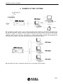
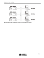
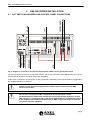
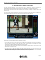
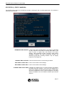
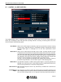
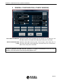
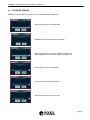
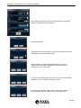
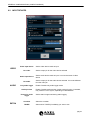
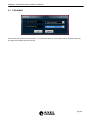
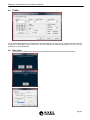
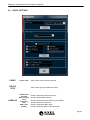
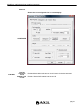
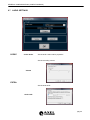
User Manual
Rel. 1.5
DML Recorder
Digital Video Logger
Via Caduti Di Sabbiuno 6/F • 40011 Anzola Emilia • Bologna • Italy +39 051 736555 • Fax. +39 051 736170
e-mail: [email protected] • web site: www.axeltechnology.com
TABLE OF CONTENTS
1 TABLE OF CONTENTS
1
2
3
4
5
6
7
8
9
10
11
12
13
14
TABLE OF CONTENTS ....................................................................................................................................2
INTRODUCTION TO DML SYSTEM ................................................................................................................3
SAFETY WARNINGS........................................................................................................................................5
EXAMPLE OF DML SYSTEMS.........................................................................................................................6
DML RECORDER INSTALLATION...................................................................................................................8
5.1 SAT TIME SYNCHRONIZER AND CONTROL PANEL CONNECTIONS .........................................8
5.2 VIDEO CONNECTIONS .....................................................................................................................9
5.3 AUDIO CONNECTIONS .....................................................................................................................9
5.4 NETWORK CONNECTIONS ..............................................................................................................9
5.5 ‘SAT TIME SYNCHRONIZER’ (GPS) RECEIVER ...........................................................................10
5.6 CONTROL PANEL............................................................................................................................10
SAT TIME SYNCHRONIZER POSITIONING .................................................................................................11
6.1 INTRODUCTION...............................................................................................................................11
6.2 SAT TIME SYNCHRONIZER POSITIONING ...................................................................................11
6.3 INSTALLATION WARNINGS............................................................................................................11
DML RECORDER - BASIC OPERATING PRINCIPLES ................................................................................13
DESCRIPTION OF BASIC FUNCTIONS ........................................................................................................14
8.1 DESCRIPTION OF MAIN WINDOW CONTROLS ...........................................................................15
8.2 STATISTICS ( ‘STATS’ WINDOW)...................................................................................................17
8.3 DML RECORDER - NAME FILE DESCRIPTION.............................................................................19
8.4 ALARMS ( ‘ALARM’ WINDOW) ........................................................................................................20
GENERAL CONFIGURATION (‘CONFIG’ WINDOW) ....................................................................................22
9.1 EZ SETUP WIZARD .........................................................................................................................24
9.2 INPUT DEVICES...............................................................................................................................27
9.3 CROSSBAR ......................................................................................................................................29
9.4 VIDEO SETTINGS ............................................................................................................................31
9.5 AUDIO SETTINGS............................................................................................................................33
9.6 ALLARMS SETTINGS ......................................................................................................................34
9.7 CALCULATOR ..................................................................................................................................34
9.8 LOAD CONFIGURATION ................................................................................................................34
9.9 SAVE CONFIGURATION .................................................................................................................34
RECORDINGS SCHEDULER.........................................................................................................................34
10.1 INSERIMENTO / MODIFICA SINGOLA PROGRAMMAZIONE .......................................................34
GRAPH CONFIGURATION WINDOW ...................................................Errore. Il segnalibro non è definito.
WATCH DOG ..........................................................................................Errore. Il segnalibro non è definito.
TECHNICAL SPECIFICATIONS .....................................................................................................................34
WARRANTY ....................................................................................................................................................34
pag.2
INTRODUCTION TO DML SYSTEM
2 INTRODUCTION TO DML SYSTEM
•
Reliable and field proven for continuous, digital recording 24 hours / 7 days a week
•
User friendly and convenient to operate for optimum utilization of all features.
•
MPEG-1, MPEG-2, MJPEG, MPEG-4, DIVX recording formats. Several additional formats available on
request.
•
Matches the need for logging of TV emissions/broadcasting or advertising certification, as required by the
laws in force in many countries
•
Suitable also in other areas of activity, such as surveillance, technical monitoring and close circuit video
cameras for patrol systems
•
User definable log periods (1 week, 1 month, 3 months, etc)
•
Low, medium or high recording resolution/quality (even at broadcast quality) according to the actual
configuration and settings
•
Automatic overwriting of oldest A/V files after the set logging period has expired
•
Variable compression/quality factor
•
Multichannel recording
•
Totally maintenance free
•
Avoids all problems related to mechanical video recorders (Time Lapses) such as tapes consumption,
cassette replacement, long time to access recordings, low A/V quality, low quality still images, etc.
•
Image Time Stamping from GPS receiver (supplied)
•
System status shown on dedicated Control Panel (optional)
•
Composite, S-VHS video and RF inputs
•
Auto-diagnostic software tools
•
Ip streaming in Windows Media Format
•
Alarm notification via email or SMS (opcioanl GPRS modem required)
•
Instant access and playback of recorded contents from any remote computer running DML–Player
application (free of charge).
•
Multiple searching criteria of recorded contents (by time, by date, etc)
•
Superimposing of recording date & time on played contents.
•
Capability to reproduce video on external Pal or NTSC monitors*
•
DML monitor software for remote monitoring of multichannel systems.
pag.3
INTRODUCTION TO DML SYSTEM
* depending on the video card installed on the Pc running the DML-Player
Optionals:
-
- Supervisor for automatic alarms management and system recovery (source switching, spare unit
activation, serial and GPI controls, etc).
BASIC TECHNICAL DATA:
Video Input: PAL / NTSC
Audio formats: Stereo, Mono
Full frame rate
Based on XP PRO o.s.
AC Main: 220 / 110 V, 50/60 Hz
pag.4
SAFETY WARNINGS
3 SAFETY WARNINGS
A correct installation and an optimum level setting are crucial for a good operating and the exploitation of all
the equipment capabilities. Please pay attention to the following notes:
The installation and servicing instructions in this manual are for use by qualified personnel only.
●
Read All Instructions. All safety and operating instructions must be read before operating the product.
They also must be retained for future reference, as it contains a number of useful hints for determining
the best combination of equipment settings for Yr particular application.
●
Heed All Warnings. All warnings on the product and those listed in the operating instructions must be
adhered to.
●
Heat. This product must be situated away from any heat sources such as radiators or other products
(including power amplifiers or transmitters) that produce heat.
●
Power Sources. This product must be operated from the type of power source indicated on the marking
label and in the installation instructions. If you are not sure of the type of power supplied to your facility,
consult your local power company. Make sure the AC main voltage corresponds to that indicated in the
technical specifications. If a different voltage (ex. 110/115 VAC) is available, open the equipment closure
and set the voltage switch on the main supply circuit, located behind the AC socket
●
Power Cord Protection. Power supply cords must be routed so that they are not likely to be walked on
nor pinched by items placed upon or against them. Pay particular attention to the cords at AC wall plugs
and convenience receptacles, and at the point where the cord plugs into the product
●
Clean only with dry cloth
●
Use only with a cart, stand, tripod, bracket, or table specified by the manufacturer, or sold with
the apparatus. When a cart is used, use caution when moving the cart/apparatus combination
to avoid injury from tip-over.
●
Lightning. For added protection for this product during a lightning storm, or when it is left unattended and
unused for long periods of time, unplug it from the AC wall outlet and the audio connections. This will
prevent damage to the product due to lightning and power line surges
●
Installation. Configuration and installation should only be carried out by a competent installation
engineer
●
Cabling. Using high quality wires, well protected. Make sure the cable integrity.
●
Equipment design. This manual images could differ a bit from the equipment actual design
This symbol alerts you to the presence of dangerous voltage inside the closure –
voltage which may be sufficient to constitute a risk of shock. Do not perform any
servicing other than that contained in the operating instructions. Refer all servicing to
qualified personnel
The exclamation point within an equilateral triangle is intended to alert the user to the
presence of important operating and maintenance (servicing) instructions in the
literature accompanying the appliance.
pag.5
EXAMPLE OF DML SYSTEMS
4 EXAMPLE OF DML SYSTEMS
Fig 1 Overview of a DML system. The Pc running the DML Player software is networked to the DML server
(i.e. the DML Recorder). If that Pc features a video board with Pal or Ntsc outputs, You may reproduce DML
contents on regular Tv monitors or record them on external video tapes. Through DVD or CD writers
(optional), DML contents may also be exported on those mobile storage devices and reproduced on
consummer home players. The printer allows for printing of selected video frames.
Fig 2 One DML Recorder is networked with three PCs running DML Player software.
pag.6
EXAMPLE OF DML SYSTEMS
Fig 3 Two DML Recorder are networked with two PCs running DML Player software.
pag.7
DML RECORDER INSTALLATION
5
LAN
PIN TO PIN
PIN TO PIN
VGA
KEYBOARD
AC SOCKET
PWS BOTTON
VOLTAGE SET
GPS RECEIVER
CONTROL PANEL
SAT TIME SYNCHRONIZER AND CONTROL PANEL CONNECTIONS
MOUSE
5.1
DML RECORDER INSTALLATION
Fig 4: diagram of connections for Sat Time Synchronizer (GPS receiver) and Control Panel
The picture shows connections of DML rear panel to Sat Time Synchronizer (GPS RECEIVER) and Control
Panel (optional) by means of 9 poles serial cable (supplied).
Audio /video connections are not shown, as they could differ, depending on the actual hardware configuration
and installed options of Yr machine.
Please connect the Sat Time Synchronizer and the Control Panel unit with DML
machine turned OFF.
Do not alter in any way the DML configuration and do not add or remove
hardware/software components without Axel Technology written permission. Proper
DML operation is guaranteed ONLY with the hardware/software configuration present
at the shipment. No authorized modifications to DML causes warranty to be void and
can yield to improper operation.
pag.8
DML RECORDER INSTALLATION
5.2
VIDEO CONNECTIONS
The video INPUT supports either S-Video or Composite video signals (Pal NTSC standards).
Video connections
•
Composite plug: connect the video source to the Composite video input through a good quality cable (75
ohm impedance) .
•
Super Video plug: connect the video source to the SVHS video input (4 PIN connector) through a suitable
cable.
•
S-Video connector pin-out:
•
Pin
Name
Description
1
2
3
4
GND
GND
Y
C
Ground (Y)
Ground (C)
Intensity (Luminance)
Color (Chrominance)
RF plug: connect the antenna source to the RF input through a good quality cable (50 ohm impedance) .
Please provide highest quality video signals, as the low-quality ones might seriously affect DML
operation.
Whenever the DML Player computer is equipped with video board featuring Pal or Ntsc video output
(f.i. Matrox G550, ATI Graphics card), You may monitor on external TV equipment the Video signal at
the input (loopback or passhrough function).
Playback of recorded contents is achievable on external PCs running DML Player application.
5.3
•
AUDIO CONNECTIONS
Audio in plug: connect the audio source to the audio input through a good quality cable .
5.4
NETWORK CONNECTIONS
The DML Recorder is equipped with Network Card with TCP/IP installed. The connection with one or more
DML Player PCs may be achieved through direct link (crossed cable) or through Hub/Switch (not crossed
cable).
For DML Recorder and DML Player networking, refer to skilled technician or to the network Administrator.
TCP /IP protocol is also used to control the DML Recorder from remote (providing Rec, Stop commands over
the network)
pag.9
DML RECORDER INSTALLATION
5.5
‘SAT TIME SYNCHRONIZER’ (GPS) RECEIVER (optional)
The GPS receiver “Sat Time Synchronizer” by AXEL TECHNOLOGY must always be connected to DML,
EVEN IF SATELLITE SIGNAL IS VERY WEAK OR NOT AVAILABLE.
On request, AXEL TECHNOLOGY provides 30 mt cable for easier receiver positioning.
The receiver must be firmly connected to DML rear panel, as shown on Picture 4.
The improper connection of GPS Receiver generates an ALARM in the ALARMS window. In the event of
ALARM, please make sure the Sat Time application is installed, configured and running.
If the STS is not correctly receiving, the related indication is showed on the DML Recorder main window.
When the STS is not receiving, DVL runs using its internal Bios clock.
5.6
CONTROL PANEL (optional)
The Control Panel unit is an optional, external unit which shows DML operating status along with current time
and date (included possible alarms).
The Control Panel is equipped with a mutable Buzzer, for more effective signalling of Alarms.
The Control Panel is connected to the DML Recorder via a supplied serial cable. Please refer to Fig 4.
ST1
INPUT
INTERFACE
SYSTEM
MONITOR
ST2
pag.10
SAT TIME SYNCHRONIZER POSITIONING
6 SAT TIME SYNCHRONIZER POSITIONING
6.1
INTRODUCTION
The GPS module receives data from various satellites belonging to the Global
Positioning System (GPS), a satellite-based locating and navigating system
that allows a user to determine his exact position on earth.
GPS satellites also transmit time data with extremely high precision. AXEL Sat
Time Synchronizer acquires exact time information and synchronizes the PC’s
clock with the received signal. The receiver has a RS232 connector for use
with PC or laptop. Power is directly supplied through a special loop connector
from PC power supply.
6.2
SAT TIME SYNCHRONIZER POSITIONING
To allow best performance receiver must have free view to the sky. Satellite signal strength strongly affects
receiver performance, but with open sky sight (best possible environment) perfect operation is guaranteed
almost wherever on the planet.
Perfect system performance may eventually be possible in common indoor environments, on condition that
the receiver is located close to large windows and the received signal be strong enough.
6.3
INSTALLATION WARNINGS
•
Before starting Sat Time Synchronizer, please make sure every connection is correct.
•
Use supplied cables only.
•
The installation must be realized by skilled technicians.
•
In case of technical problems or faults do not open the box for any reason and contact local AXEL
TECHNOLOGY representatives
•
Images on this manual could differ a bit from Sat Time Synchronizer actual design.
•
Read this instruction manual in detail and keep it for future use.
•
Always locate the receiver away from magnets and strong magnetic fields
•
Do not use serial cables longer than 25 meters
•
Do not pinch the cable, in particular with doors and windows.
•
Before connecting/disconnecting the receiver, make sure the computer is off.
pag.11
SAT TIME SYNCHRONIZER POSITIONING
•
The receiver is protected against small water drops but it is NOT water-proof. If located outside, do NOT
expose to rain and do not place in roof places which could water-filled in the event of strong rain.
Recommended position is close to walls or under protective roofs.
•
Do not expose to direct sun rays.
•
Do not expose to any acid substance or other unusual environmental conditions.
•
Warranty does not cover damage caused by improper use of the unit.
pag.12
DML RECORDER - BASIC OPERATING PRINCIPLES
7 DML RECORDER - BASIC OPERATING PRINCIPLES
DML is a 24/7 non stop AV recorder. DML captures audio and video using any Windows Directshow input
device and stores the information in files on hard disk using any audio and video software codec. Recordings
are segmented into 1 hour files (usually), until hard disk is full, and then oldest files are automatically replaced
by new ones. Common configuration implement DivX codec for video and MP3 codec for Audio, producing
industry standard files, which can be distributed to many electronic devices such as home DVD players,
handheld devices, ecc.
DML works on Windows XP SP2 operating system, and is optimized for non assisted, automatic operation.
A special Mux switching technology assures that no video or audio frames are lost between consecutive files.
The bit-rate and the audio/video compression ‘quality’ depend on various factors such as video digitizing size,
framerate, codec properties and quality of incoming signal. Computer CPU needs to be adeguate, especially
for multichannel configurations.
The amount of recording days (i.e. the target recording duration, as required by the customer) is entered in
the alarm parameters window, but essencially depends only on codec settings (datarate) and available disk
space A separate disk partition, different from OS partition, is suggested, since DML will fill up almost
completely the media target disk(s).
During the capture process, Dml automatically monitors the average Data Rate (A+V) and calculates the
projected recording time on the basis of Hard Disk capacity* (i.e. Archive capacity).
In the event the number of minimum or maximum recording days cannot be satisfied at the present datarate,
an error message will inform the operator about parameter mismatch. All alarms may also be notified by email
or SMS (optional GPRS modem is required.)
pag.13
DESCRIPTION OF BASIC FUNCTIONS
8 DESCRIPTION OF BASIC FUNCTIONS
The DML Recorder application can be launched from the Pc desktop, by clicking the relevant icon.
Installshield will automatically add an automatic start of the application in the Windows startup menu.
Once launched, the DML Recorder will automatically start recording, according to settings made in the
CONFIG mask.
The main Recorder window reproduces the video source and shows the input audio level on Vu Meters. It is
recommended to adjust the audio source volume so that meters never hit the red zone.
At the bottom, three fields display main data related to recording:
- The first filed (at the top) is active when lunching the DML Recorder application and notify about loading of
filters and software components for DML Recorder operation. It also displays error messages in the event
of malfunctioning. Double clicking this field opens the LOG window.
- The second field show current time and date. Time information is derived from Pc clock, which is kept
updated from the GPS time signal.
- The third field (on the right side) displays the target recording days (as set by the user) and the real
recording duration (switched), as calculated, second by second, on the basis of the actual compressed
video bit rate. Real recording duration will be equal or longer than the target duration.
pag.14
DESCRIPTION OF BASIC FUNCTIONS
8.1
DESCRIPTION OF MAIN WINDOW CONTROLS
It runs recording. In particular, recording is on when REC button colour is bright red, while it is
stopped (i.e the STOP button has been pressed) when REC button colour is pink (light red).
Recording is by default engaged when launching the Recorder (see also the CONFIG mask for
further settings). Every time recording task is resumed, a new A/V file is created. Clicking on
the button when in Rec mode issues a SWITCH command, which forces a new file to be
created and the old one to be closed.
It stops recording. Every time the Recorder stops, the current A/V file being recorded is closed.
When recording is stopped, REC button colour is pink/light red.
It opens a dedicated mask (STATISTICS) which shows the current status of main recording
parameters (see relevant Section). The STATS button can be pressed while recording is
engaged.
The ‘ALARM’ label blinks and changes its size whenever one or multiple problems are
detected.
If ‘ALARM’ label size is constant and it doesn’t blink, the Recorder runs properly. The ALARM
button recalls a dedicated window that displays the current status of main system parameters
(see relevant Section).
It opens the dialogue mask for general system configuration The CONFIG button is enabled
only when recording is stopped.
It opens the recording scheduler window, with the purpose of enabling automatic stop and start
of dml recording according to date and time.
Clicking on the notepad icon opens the log file of the dml recorder. As shwn in the next window.
When Windows Media Encoder is enabled in config menu, this Icon opens the dialog window for
checking encoder status, as shown in next window.
pag.15
DESCRIPTION OF BASIC FUNCTIONS
pag.16
DESCRIPTION OF BASIC FUNCTIONS
STATISTICS ( ‘STATS’ WINDOW)
The STATS button opens the STATISTICS window, showing all main recording parameters. The window is
refreshed every second.
ESTIMATED REC LENGHT It shows the actual recording days. This value is calculated
at every second on the basis of Average Data Rate. If the
value is lower or higher than user preset in the alarm
settings, DML generates an alarm. Normally, under optimal
operating conditions and VBR compression formats, the
estimated (projected) recording duration may be slightly
longer than the target one.
CURRENT REC FILE SIZE It shows the actual size of A/V file being recorded.
MUX VIDEO CODEC INFO It show current video codec settings
MUX AUDIO CODEC INFO It show current video codec settings
CURRENT REC START TIME It displays the starting time of current recording. By default,
the DML Recorder creates a new file at the beginning of
each hour (opening at XX.00.00 and closing at XX.59.59,
where XX indicates the hours). Further settings on recording
start are available from the CONFIG window (see relevant
Section).
pag.17
DESCRIPTION OF BASIC FUNCTIONS
NEXT REC START TIME. It shows the start time of next recording file, according to
settings done in the CONFIG window. By default, the DM
Recorder creates a new file at the beginning of each hour
(opening at XX.00.00 and closing at XX.59.59, where XX
indicates the hours).
NEXT RESET DEVICE TIME It show the date and time the input device will be reset. This
setting depends on the parameters in the config window. A
reset of the input device is suggested periodically (every
month or two), to reset Windows memory and close
completely capture process.
AVERAGE DATA RATE It shows the overall Data Rate (audio + video) being
transferred on disks. It is refreshed at every second on the
basis of size of file being recorded and of recording start
time. On the basis of average datarate, total disk capacity is
calculated and if out of alarm parameters, an alarm will be
issued. Alarms are issued after 10 minutes of recording to let
average parameters stabilize.
INSTANT DATA RATE It shows the overall Data Rate (audio + video) being
transferred on disks. It is refreshed at every 5 seconds on
the basis of size of file being recorded in the last 5 seconds.
An alarm will be issued if value goes below Instant Data Rate
Threshold specified in alarm settings.
MUX STATUS It show status of the capturing engine
CURRENT REC FILE NAME It shows the complete name and path of file being recorded.
It is the same name shown in the archive (see next
Paragraph).
MUX VIDEO FRAMES It shows the current count for the video frames passed to the
encoder of the current file. It shows passed/rejected/dropped
frames. Rejected and dropped frames are symptom of
unhealthy system or configuration.
MUX AUDIO PACKETS It shows the current count for the audio packets passed to
the
encoder
of
the
current
file.
It
shows
passed/rejected/dropped frames. Rejected and dropped
frames are symptom of unhealthy system or configuration.
MUX TOTAL VIDEO FRAMES It shows the current count for all the video frames passed to
the encoder since the last input device reset. It shows
passed/rejected/dropped frames. Rejected and dropped
frames are symptom of unhealthy system or configuration.
MUX TOTAL AUDIO PACKETS It shows the current count for all audio packets passed to the
encoder since the last input device reset. It shows
passed/rejected/dropped frames. Rejected and dropped
frames are symptom of unhealthy system or configuration.
SHOW ENCODER When Windows Media Encoder is enabled in config menu,
this button opens the dialog window for checking encoder
status.
CALCULATOR This button opens the DML recorder calculator window, as
described in dedicated section.
pag.18
DESCRIPTION OF BASIC FUNCTIONS
8.2
DML RECORDER - NAME FILE DESCRIPTION
The name of DML Recorder files contains various information concerning their status, date and time of
creation, duration and Recorder name. The file name format is as following:
O/X
YYYY-MM-DD
hh.mm.ss
HH.MM.SS XXXXXX.yyy
Where:
O/X
The ‘x’ mark indicates the file has been correctly created (header is complete) and denotes a
VALID recording. The ‘o’ mark
indicates an improperly created file (header uncompleted).
YYYY-MM-DD Recording date in the extended format YEAR – MONTH – DAY
hh.mm.ss Recording start time (time of file creation)
HH.MM.SS File duration in HOURS.MINUTES.SECONDS. This field is updated when closing the file.
XXXXXX It shows the DML Recorder name (or Channel ID)
.yyy File extension, as stated in the CONFIG mask
All fields are separated by double space.
NOTE: the time of recording start is expressed in GMT format (Greenwich Mean Time) / UTC (Universal Time
Conversion) as this format is Day-light season invariant.
The DML Recorder appends to each A/V file a 19 Byte field containing all data (duration, start time and data,
etc) associated with the file itself. This way, even if the file is renamed, the DML Player can always identify
files to be played and recover their time/data information
pag.19
DESCRIPTION OF BASIC FUNCTIONS
8.3
ALARMS ( ‘ALARM’ WINDOW)
The ALARM window (which is displayed when pressing the ALARM button on the main screen) shows the
status (OK or ERROR) of basic DML Recorder operating elements, according to following table, which also
serves as simple ‘troubleshooting’ guide.
GPS SIGNAL When OK, the GPS signal recovered by Sat Time Synchronizer receiver is strong
enough to get a valid time reference. The ERROR condition corresponds to having
Red and Yellow lights on traffic-light Icon on Sat Time Synchronizer control
software
VIDEO INPUT When OK, the video signal at the DML input is Valid. The DML Recorder checks
Luminance level of one pixel out of eight on the image at the input every 5 seconds.
If all Pixel luma value stays under the specified threshold and for the specified time
as in set in the alarm settings window the input video signal is considered absent.
The parameter Safe Guard Area (alarm settings window) defines the image area
where the control is applied as a horizontal band on the video window.
This way, You may prevent the Recorder from applying the luminance control to
permanent image elements, such as station Logos or Time Stamping labels.
AUDIO INPUT The Recorder analyzes Vu Meter activity (either Right or Left) and generates an
ERROR in the event there are no audio peaks beyond a stated audio threshold for
more than the specified time in the alarm settings window.
DISK ACTIVITY DML Recorder analyzes if there is any disk activity on Media drive. Otherwise an
alarm is issued.
STORAGE TOO Id the storage is to small to contain the minimum days of recording specified in the
SMALL alarm settings window, an alarm is issued. This alarm has memory, and to clear the
error the Clear storage button is to be pressed. Recording stops automatically is
pag.20
DESCRIPTION OF BASIC FUNCTIONS
corresponding parameter is set in the Config window.
ESTIMATED DAYS When OK, indicates the average A/V Data Rate does not exceed the parameters
REC set in the alarm settings window, both for minimum and maximum days range.
INSTANT DATA RATE When OK, indicates that current instant datarate is above threshold specified in
alarm settings window.
INPUT DEVICE Indicates that input capture device has been initialized correctly
BEEPER ACTIVE When OK, the Beeper built-in into the Control Panel is enabled. This Beeper
sounds as soon an Alarm (no matter of its type) is generated. To mute the Beeper,
press the encoder (rotative control) on the Control Panel.
CLEAR STORAGE When a “Storage too small” error is issued, error is retained even is datarate lowers
ERROR under the acceptable threshold. Press this button to reset error status
ALARM SETTINGS Opens the Alarm settings Window to let user configure all alarm threshold
parameters.
EMAIL RECIPIENTS Insert all email addresses to be advised when an alarm up rises. Recipients should
be separated by the “;” sign.
SMTP SERVER NAME Specify the name of the SMTP server to be used to send email notifications
TEST EMAIL Press this button to instantly send an email to the specified recipients for testing
purposes
SMS PHONE NUMBER Specify the cellular phone number to which alarm notifications will be sent
MODEM COM PORT Specify the com port to which the GPRS modem (optional) is connected.
TEST SMS Press this button to instantly send a SMS to the specified phone number for testing
purposes
pag.21
GENERAL CONFIGURATION (‘CONFIG’ WINDOW)
9
GENERAL CONFIGURATION (‘CONFIG’ WINDOW)
PATH FOR RECORDINGS Specifies the folder where all media files are captured. To view files from LAN
this folder must be in a shared drive. DML player must point to this folder.
PATH FOR STATUS AND Specifies where DML stores log files, current image, current status file. To
LOGS view status with DML monitor application, this filder must be in a shared drive.
DML monitor must point to this folder.
In order to guarantee best DML Recorder operation, it is highly recommended to save A/V files in
Partitions or Volumes distinct from the Operating System ones.
pag.22
GENERAL CONFIGURATION (‘CONFIG’ WINDOW)
LANGUAGE It sets the language used in all DML Recorder windows and masks. Restart
application for new setting to take effect.
CHANNEL ID It denotes the DML Recorder name, as it appears on all recorded files and
throughout DML Player use. Normally, it is the name of the Tv station /
broadcaster or the channel frequency being recorded (f.i., BBC ONE, CNN,
BLOOMBERG SAT, etc).
START RECORDING When selected, recording is automatically engaged when launching the DML
AUTOMATICALLY Recorder application
REC FILE TYPE It is the extension of A/V files created by the Recorder. The chosen extension
must match the audio/video coding formats.
STOP REC IF STORAGE
TOO SMALL
IF storage is too small for the selected days duration, capturing process is
stopped automatically to preserve recordings.
RESET INPUT Reset hardware device at the selected time interval. Resetting input device
stops capturing for 15/20 seconds and resets application memory usage. A
input device reset is suggested every month or two.
STOP REC AT THE HOUR When selected, DML Recorder creates a new file at the beginning of each
hour (opening at XX.00.00 and closing at XX.59.59, where XX indicates the
hours). This is the recommended operating mode (pre-set by default). The
following numeric entry defines a recording preroll to compensate capture
delays. For multichannel configurations a different negative value is suggested
so switch is never at the same time.
STOP REC EVERY n When selected, allows to set the max duration of each recording file
MINUTES
STOP REC SIZE IN MB When selected, allows to set the max size of each recording file. This may be
proven useful when creating files for removable supports such as CD ROM
and DVDs.
DISABLE VIDEO PREVIEW If selected, the preview window is not shown on main window, (less CPU
WINDOW USAGE)
REMOTE CONTROL PORT Specifies the com port for DML control panel
STREAMING WM PORT If checked, it enables the video streaming on selected port (normally 8080, the
one used by internet)
STREAMING BITRATE Sets the video stream bitrate.
pag.23
GENERAL CONFIGURATION (‘CONFIG’ WINDOW)
9.1
EZ SETUP WIZARD
EZSetup is a wizard which will guide you to the DMLRecorder configuration.
Select the language for the application
WARNING: all parameters will be overwritten.
Select the drive where you want to save recordings. It is
recommended not to choose the operating system drive.
Select log type, audio or audio/video
Select the video device used as input
Select the audio device used as input
pag.24
GENERAL CONFIGURATION (‘CONFIG’ WINDOW)
The EZsetup wizard shows the general input device configuration.
Usually no modifications are necessary.
Confirm parameters.
Select minimum amount of days you want to log. Maximum amount
automatically is set to double this value
Specify whether to install suggested applications. If this is a
multichannel configuration, installation of these application is
necessary only for first channel.
If you want to install DirectX, click on YES. If you don’t have directx
installed on your PC, DML Recorder will not work
f you want to install DivX codec, click on YES. DivX is used for
encoding Media files and is DML recorder preferred codec.
pag.25
GENERAL CONFIGURATION (‘CONFIG’ WINDOW)
If you want to install Media Encoder, click on YES. This software is
used by DML Recorder to make video streaming over IP.
If you want to install ULTRA Vnc, click on YES.
With this software you can control DML from a remote PC via LAN or
internet.
Remeber to adjust all codec settings to match desired number of days
recording.
Reboot PC
At the end of the wizard the system will reboot.
pag.26
GENERAL CONFIGURATION (‘CONFIG’ WINDOW)
9.2
INPUT DEVICES
Video input device
VIDEO
Pin video
Audio input device
Pin audio
AUDIO
Only audio logger
Audio preview
Picture for audio
logger
Crossbar
EXTRA
TUNER
Set the video device used as input
Set the output pin for the video device selected
Set the audio device used as input. It can be the same of video
device
Set the output pin for the audio device selected. It must be different
from the video pin
Enable / Disable only audio logger mode
Enable / Disable audio preview. Audio preview function, if enabled,
may cause AV out of synch, depending on MB hardware.
Set the static image used during audio logging
Select the crossbar
Select which TUNER (if available) you want to use
pag.27
GENERAL CONFIGURATION (‘CONFIG’ WINDOW)
9.3
CROSSBAR
If the device has more than one input port, you must select which one you want to use. If the device has only
one input this windows will not be shown
pag.28
GENERAL CONFIGURATION (‘CONFIG’ WINDOW)
9.4
TUNER
Tuner configuration depends on standards in use and are specific for each country. Sometimes it is necessary
to specify an equivalent country code since not all countries are correctly catalogued. For PAL use 49
(Germany) or 44 (Great Britain)
9.5
Video Size
This button will initialize video input device to specified Video Size, framerate and color space.
pag.29
GENERAL CONFIGURATION (‘CONFIG’ WINDOW)
9.6
VIDEO SETTINGS
CODEC
Codec video
FIELDS
TYPE
OVERLAY
Set the video codec and its properties
Set the fields type (for interlaced modes)
Default date
and time
Date and time
Tuner
frequency
Text
GMT Label
ID DML
Enable / Disable the standrad overlay
Enable / Disable date and time
Enable / Disable the tuner frequency (if available)
Enable / Disable a custom text
Enable / Disable the GMT Label
Enable / Disable the DML Channell id label
pag.30
GENERAL CONFIGURATION (‘CONFIG’ WINDOW)
Channel
Shows the font configuration for on screen display
CONFIGURE
EXTRA
Use DS
reference
clock
Subtitle DVD
in AVI
Enabled/disable Microsoft refernce clock (Use only for debug purposes)
Enable / Disable DVD subtitles into the AVI file
pag.31
GENERAL CONFIGURATION (‘CONFIG’ WINDOW)
9.7
AUDIO SETTINGS
CODEC
Codec Audio
Set the audio codec and its properties
Set the recording volume.
Volume
EXTRA
Set the audio shiift.
Audio shift
pag.32
GENERAL CONFIGURATION (‘CONFIG’ WINDOW)
pag.33
GENERAL CONFIGURATION (‘CONFIG’ WINDOW)
9.8
ALLARMS SETTINGS
When th recording excede these limits, it throws an allarm.
MINIMUM REC LENGHT
IN DAYS
It sets the mimumum threshold expressed in days of the recording total length
according to available hard disk space.
MAXIMUM REC LENGHT
IN DAYS
It sets the maximum threshold expressed in days of the recording total length
according to available hard disk space.
INSTANT DATARATE
THESHOLD Mb/s
It sets the minimum threshold (expressed in megabits per second) for a valid
instant Data Rate.
VIDEO THRESHOLD (in
%)
It sets the minimum threshold for a valid video signal (see also ‘ALARM’
window). NOTE: the small gray field on the right shows the current video level
at the input (f.i., the figure shows a current input level of 88, while threshold is
set to 12). For perfect threshold tuning, read out the background (‘floor’) noise
level with the video input disconnected (or with the video source in ‘fault’
condition) and set the video threshold at that level.
VIDEO ERROR TIMEOUT
SEC
It sets the timeout for Video presence alarm. After the specified number of
seconds, if video level is always below threshold, an alarm will be issued.
SAFE GUARD AREA
It defines, on each frame, the image area where the Luminance control is
applied. See also ‘ALARM’ window – Video Input item.
AUDIO THRESHOLD
It sets the minimum threshold for a valid audio signal (see also ‘ALARM’
window). NOTE: the small gray field on the right shows the current video level
at the input (f.i., the figure shows a current input level of 90, while threshold is
set to 80). For perfect threshold tuning, read out the background (‘floor’) noise
level with the audio input disconnected (or with the audio source in ‘fault’
condition) and set the audio threshold at that level.
pag.34
AUDIO ERROR TIMEOUT
SEC
It sets the timeout for audio presence alarm. After the specified number of
seconds, if audio level is always below threshold, an alarm will be issued.
pag.35
9.9
CALCULATOR
The calculator is a useful tool used to calculate recording size according to bitrate and available space
To find the result just select which parameter you want to block, than set the others parameters
pag.36
9.10 LOAD CONFIGURATION
Load a configuration file
9.11 SAVE CONFIGURATION
Save the current configuration to a file
pag.37
RECORDINGS SCHEDULER
10 RECORDINGS SCHEDULER
DML recorder schedule allows automatic STOP and START of recordings according to specified date and
time.
In the list on left, all saved schedulers are shown.
10.1 ADD / MODIFY A SCHEDULER ELEMENT
The recordings (or the end) can be activate in two ways
pag.38
RECORDINGS SCHEDULER
•
•
If you select Calendar, the element will run once on the selected day.
If you select a day, the element will run cycling on the selected weekday.
pag.39
TECHNICAL SPECIFICATIONS
11 TECHNICAL SPECIFICATIONS
•
Operating System: Microsoft Windows 2000 Professional.
VIDEO Specifications
Recording Format
Compressed Data Rate
Frame Rate
Video Standards
TV Video formats
MPEG-1, MPEG-2, MJPEG, MPEG-4 e DIVX
Variable and user-settable
30 fr/sec (NTSC) – 25 fr/sec (PAL)
PAL B/G – PAL M – PAL N - NTSC – NTSC 44 – NTSC c
PAL: 640 x 480
AUDIO Specifications
Recording Format
Mode
Bit rate
MPEG1 Layer III
Stereo
40÷192 KBits/sec
Other Specifications
Satellite Receiver
Lan Card
DML PLAYER
Sat Time Synchronizer
Power Supply
Dimensions
Weight
AXEL Sat Time Synchronizer for date and time synchronization with
GPS.
100 Mbit/sec PCI Card (RJ 45 connector)
Recording searching/ viewing software (running on Windows
98SE/NT/2000/XP)
+ 5V provided by the PC power supply
Height: 100 mm
Wide: 65 mm
Depth:38 mm
240g
12 WARRANTY
The manufacturer offers a 1-year ex works warranty.
Do not open the equipment. The warranty shall be voided if any of the warranty seals are broken.
The manufacturer shall not be liable for damage of any kind deriving from or in relation to incorrect use of the
product.
pag.40