1
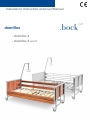
Installation Instruction and User Manual
domiflex
. domiflex 2
. domiflex 2 wash
Dear valued customer,
Thank you for purchasing a health care bed from Hermann Bock GmbH.
You made a good buying choice because this health care product has a
long product life and provides superior functionality and the highest level
of safety. Our electrically operated health care beds guarantee optimal lying comfort and allow professional care at the same time. This product
was designed with a focus on the elderly, whose confidence must be reinforced and whose life needs protection. With this health care product, we
meet these requirements.
We urge you to prevent potential malfunctions and the risk of accidents
by complying strictly with the safety and operating instructions and by
carrying out the necessary maintenance.
Sincerely yours,
Klaus Bock
2
Content
1 Preface and general instructions .............................................................................. 4
1.1
Intended use ....................................................................................................... 4
1.2
Definition of the user group ................................................................................ 5
1.3
Safety instructions............................................................................................... 5
1.4
Service life / warranty ......................................................................................... 7
1.5
Type plate (example): ......................................................................................... 8
2 General description of the functions ........................................................................ 9
3 Electric parts .......................................................................................................... 14
3.1
Drive .................................................................................................................. 14
3.2
Level adjustment drive ...................................................................................... 14
3.3
Lockable hand control (first-fault protected) .................................................... 14
3.4
Hand control (symbols) ..................................................................................... 15
3.5
Hand control (lock functions) ............................................................................ 16
3.6
Caution: Electric drive ....................................................................................... 17
4 Drives ..................................................................................................................... 18
4.1
24 Volt drives .................................................................................................... 18
4.2
Drive systems .................................................................................................... 18
4.3
The external switch mode power supply .......................................................... 18
5 Assembly and operation ......................................................................................... 19
5.1
Technical data ................................................................................................... 19
5.2
Model series domiflex 2 .................................................................................... 20
5.3
Transport system .............................................................................................. 24
5.4
Emergency lowering - back part or foot part .................................................... 26
5.5
Disassembly ....................................................................................................... 27
5.6
Transport, storage and operating conditions.................................................... 27
5.7
Function notes .................................................................................................. 27
5.8
Disposal ............................................................................................................. 27
5.9
Troubleshooting ................................................................................................ 28
6 Accessories ............................................................................................................. 29
6.1
Special dimensions ............................................................................................ 29
6.2
Assembly – bed extensions ............................................................................... 30
6.3
Assembly – accessories ..................................................................................... 31
6.4
Mattresses......................................................................................................... 33
7 Cleaning, maintenance and disinfection ................................................................ 34
7.1
Cleaning and maintenance ................................................................................ 34
7.2
Disinfection ....................................................................................................... 35
7.3
Avoidance of hazards ........................................................................................ 35
7.4
Cleaning in cleaning facilities ............................................................................ 35
8 Guidelines and manufacturer´s declaration ........................................................... 36
9 Declaration of conformity ...................................................................................... 38
10 Regular technical safety inspections with service .................................................. 39
3
1 Preface and general instructions
The various bed systems from Hermann Bock meet special requirements for the use in
care and treatment facilities as well as for home care. Reliable functionality and a long
product life make each bed particularly valuable. Our beds need little maintenance with
proper operation and care. Each bed from Hermann Bock must pass quality testing in a
final inspection before it is shipped anywhere. The beds are manufactured according to
the current standards for medically used beds and tested accordingly.
Our beds comply with Standard EN 60601-2-52:2010. The electrical building components
comply with safety standard EN 60601-1:2006 for medical devices.
These standards divide the bed in various use areas:
1.
2.
3.
4.
5.
1.1
Intensive care in a hospital; intensive care bed
Short-term care in a hospital or other medical facility;
patient bed in the hospital
Long-term care in medical environment; stationary nursing bed
Home-care bed
Home-care nursing service
Intended use
The health care bed in elderly care or nursing homes or rehabilitation facilities improves
the positioning of patients or others in need of care, who are 12 years of age or older
and having a height of at least 150 cm. It is used to alleviate a disability and/or to facilitate the lives of people who are in need of care or to make the work of their caregivers
easier. Furthermore, the health care bed was also designed as a convenient solution for
home care of frail and elderly people as well as for home care of people with disabilities
according to standard EN 60601-1-11:2010. Therefore, the health care beds are designed to be used for the application area 3 to 4. Any other use is considered improper
and is excluded from a possible liability claim.
The Trendelenburg function is a special function that is provided upon request. It is not
part of the standard equipment. It may be used under the supervision of medical professionals. The beds, which are determined for environment type 4, are equipped with a
hand control. It cannot operate the Trendelenburg function.
The nursing bed is not suitable for use in hospitals. It is also not designed to transport
patients. The beds must be only moved inside a patient’s room, for cleaning purposes or
to allow access to the patient.
4
This user manual contains safety instructions. All persons working with the beds must
be acquainted with the contents of these instructions. Improper operation can result
in personal injuries.
1.2
Definition of the user group
Operator
Operator (e.g. medical supply stores, specialist shops, facilities and budget holders) is
any natural or legal person who uses the beds or has the bed used. The briefing on the
use of the product shall generally be conducted by the operator.
User
Users are persons whose training, experience or briefing on the product allows them to
operate the health care bed or carry out works on it. The user is able to recognize possible hazards and/or to avoid them and to assess the health condition of the patient.
Patient/resident
Persons in need of care as well as disabled and fragile people who are lying in the health
care bed.
Qualified personnel
Employees of the operator are referred to as qualified personnel. They are entitled to
deliver the health care bed, assemble, dismantle and transport it, on the basis of their
training or instructions. These persons must be instructed according to the guidelines
concerning the cleaning and disinfection of the health care bed.
1.3
Safety instructions
The intended use/operation of all moving parts is as important for the safety of the person in need of care as well as for the relatives and the caregivers/nursing staff to avoid
potentially dangerous situations. This requires the correct installation and operation of
the bed. The individual physique of the person in need of care as well as type and the
extent of their disability must be taken into account by all means when operating the
bed.
Avoid dangers, accidental motor adjustments and incorrect operation by using the disabling function. When the operator, e.g. the nursing staff/caregivers or the care providing
relative leaves the room, the entire operating functions of the bed should be disabled.
This is achieved by operating the key of the hand control. First, lower the lying surface to
the lowest position and activate the lock function with a twist of the key (located in the
keylock on the backside). Remove the key and check the function of the hand control for
safety reasons. Make sure that it is indeed locked.
5
These recommendations apply particularly:
-
if the person in need of care cannot operate the hand control safely themselves
due to certain disabilities;
if the person in need of care or the caregivers could be at risk due to those accidental adjustments;
if the side rails are in a raised position and there could be danger of trapping
and crushing;
if children are unsupervised in the room with the bed.
Always make sure that the hand control (when not in use) is securely hooked in the
support hook at the bed and cannot drop.
As a general rule, the bed should be operated by instructed nursing staff/caregivers,
relatives or in attendance of instructed persons.
When adjusting the lying surface, it is particularly important to ensure that no limbs are
placed in the side rails of the adjustment range. If the side rails themselves are adjusted,
pay attention to the correct lying position of the person in need of care.
Prior to making any electrical adjustment, it should, as a general rule, be made sure that
no limbs are positioned in the adjustment range between the chassis and the head- or
foot part, especially that there are no persons/animals in the area between the floor and
the raised lying surface. The danger of being crushed is particularly high in these areas.
The permitted person’s weight depends on the total weight of the equipment that has
been mounted to the bed (mattresses and other electronic medical devices). For the
safe capacity, please refer to the type plate on the lying surface frame of the bed.
Attention: The beds come with no special connection options for a potential equalisation. Electrical medical devices connected to the patient´s intravascular or intracardiac
system must not be used. The operator of the medical products has to ensure that the
combination of the equipment meets the requirements of EN 60601-1:2006.
6
1.4
Service life / warranty
This health care bed was developed, designed and manufactured for safe operation over
a long period of time. With proper operation and maintenance, this health care bed has
an expected service life of 7 to 10 years. The service life depends on operating conditions and frequency.
Attention:
Unauthorised technical changes to the product void all warranty claims.
This product is not approved for the North American market, particularly not for the
United States of America (USA). Distribution and use of the health care bed in these
markets, including through third parties, is prohibited by the manufacturer.
7
1.5
Type plate (example):
*
(1)
Model designation
(2)
Manufacture date: Day, month and year
(3)
Serial number: Order number - running number
(4)
Mains voltage, mains frequency and power input
(5)
Duty cycle
(6)
Drive protection class
(7)
Maximum patient weight / safe capacity
(8)
Manufacturer
(9)
Symbols (located on the right side)
* IPX 4 = Standard, IPX 6 = domiflex 2 wash
Conformity mark according to the medical device directive
IPX4
IPX6
Protection of electrical equipment against splashing water
Protection of electrical equipment against strong water jet (no high pressure)
Medical application part type B
Use only in dry rooms
Protection class II (double insulation, insulated for protection)
Within the European Union, this product must be disposed in a separate waste
collection. Product may not be disposed via the separated municipal waste.
Symbol for maximum patient weight
Symbol of capacity
Symbol for observance of the user manual
8
2 General description of the functions
Construction design and function
The lying surface with 4 function areas
The lying surface standard consists of a slatted comfort frame (as an option, it can be
also provided with a metal lying surface or special suspension systems) and is divided
into four functional areas: Backrest, solid seat, upper and lower leg rest.
The comprehensive lying surface frame is welded from a steel tube and stove-enamelled
with a PES-powder coating. The variable height adjustment of the lying surface is electric
and stepless. It is carried out by 24 V DC motors and controlled by the smooth keys of
the hand control. The backrest can be adjusted electrically. The leg part consists of a
foot support that is divided into two parts. With a touch of a button on the hand control,
each individual position can be adjusted continuously. The electronic hand control also
allows an automatic 3-way function to set a stretched leg elevation and the chest and
the knee bending part. (Availability depends on the model.) The motor of the foot part
can be replaced if necessary with a manual catch mechanism. In case of power failure,
the back and/or leg part can be lowered through disconnecting the motor mountings
(locking pin).
9
The chassis
The height adjustment of the bed takes place through two height-adjustable manual
controls. The surface of the tubular steel structure is stove-enamelled with a PESpowder coating.
The side rails
Any health care bed can be equipped on both sides with integrated side rails at a special
safety height. The side rails can be lifted and lowered through a rail. The sliding pieces
run particularly smoothly and quietly with an impact damper, and the ends are fitted
with attractive looking caps. The side rails can be easily operated through an ergonomically designed release button. Depending on the model, shorter or longer partitioned
side rail variations are available.
Operation of the continuous side rails
The release button for the adjustment of the continuous side rails is located on the upper side rail shaft in the guide rail (Fig. 1).
If lowering of the side rails is desired, reach with your fingers in the gripping groove of
the upper side rail shaft, which is designed for this purpose, and lift the side rail slightly
while pressing on the one-sided release button on the head or foot part (Fig. 2). The side
rail opens at the corresponding place and can be easily lowered downwards as far as it
will go (Fig. 3). The side rail is now diagonal. To lower the other side as well, carry out
the previously described steps on the opposite end. The side rail is now in a low position.
If the side rails should be placed in the top position to aid in fall prevention, reach with
the fingers in the centre of the upper side rail shaft of the gripping groove and pull the
side rail upwards until you hear it click into place at both ends. The side rail is now in a
pulled-up position.
Fig. 1
Fig. 2
10
The side rails serve first and foremost as an aid to fall prevention. If very thin persons in
need of care are no longer sufficiently protected by the side rails, take additional protective measures, e.g. attach additional push-fit side rails padding (accessories). The distances of the continuous side rails must be less than 12 cm. When using the continuous
side rails, they may not remain in a diagonal position.
Top tip by Bock
When using mattresses of different thickness, the minimum height of 22 cm, measured from
the top edge of the side rail above the mattress without compression, must be reached. An
additional detachable rail (available as an accessory) must be used when using higher mattresses.
Hazard note by Bock
–
–
–
–
–
Use only original Bock side rails, which are available as accessories for every health care
bed.
Use only technically flawless and non-damaged side rails with the allowed gap dimensions.
Make sure that the side rails are engaged securely.
Before installation of the side rail and each new use, inspect all mechanical parts on the
bed frame and side rails, which secure the side rails, for any possible damage.
The operation of side rails should be done with great care. Fingers can be quickly
pinched between the longitudinal pieces.
11
Fig. 1: Continuous wood and steel side rails, divided into two parts
Fig. 2: Continuous wood and steel side rails, divided into three parts
All dimensions in mm.
(*) Depending on the length of the lying surface. The dimension in brackets is optional.
Legend
A:
Distance between the head part and the side rail
B:
Height 1 of the side rail
C:
Height 2 of the side rail
D:
Width 1 of the side rail
E:
Distance between the elements within the side rail
F:
Distance between the divided side rails
G:
Distance between the lying surface and the upper edge of the side rail
H:
Height of the top edge of the side rail above the mattress without compression
I:
Thickness of the mattress for the intended use
J:
Width 2 of the side rail
K:
Smallest dimension between side rail and lying surface (or panel, if any)
L:
Distance between the foot part and the side rail
12
Item numbers
Designation
item no.
Fig. 1: Continuous wood side rail, divided into two parts
Wood side rail (set)
91907
Fig. 2: Continuous wood side rail, divided into three parts
Wood side rail (set)
80410
Fig. 3: Continuous steel side rail, divided into two parts
Steel side rail (set)
91908
13
3 Electric parts
3.1
Drive
The drive unit consists of individual drives. A switching power supply with a rectifier that
converts the input voltage into low voltage power of 35 VDC (direct current) is part of
the external control. The motors and the hand control function with this non-hazardous
low voltage. The cables are double-insulated and the mains plug has a primary fuse.
Internal emergency lowering is carried out by loosening the locking pin on the motor
mountings. Furthermore, power adjustment allows for constant speed of the functions.
Therefore, the safety functions comply with protection class II and the moisture barrier
protection type IPX4 (domiflex 2 Wash = IPX6).
The maximum duty cycle is specified on the (type plate) of the bed. For example: 10% (2
min. ON / 18 min. OFF) means that any electronic adjustment can be done within maximal 2 minutes. After that, the unit switches off for 18 minutes (protection against overheating).
If the maximum setting time of two minutes is exceeded by two minutes (e.g. someone
plays continuously with the hand control), which could lead to overheating of the servomotors, the thermal fuse immediately shuts off the power supply to the bed. After a
cooling down time of approx. one hour, the power will be again automatically supplied.
3.2
Level adjustment drive
The level adjustment of the bed takes place via two manual controls with built-in individual (DC) drives. Their adjustment range is defined by an integrated control limit
switch. The level adjustment drive is connected to the control box via a helical cable.
3.3
Lockable hand control (first-fault protected)
The base functions can be controlled safely through the eight extra large keys on the
hand control. The individual keys are marked with corresponding symbols. The servomotors run until as long as a corresponding key is pressed and held. A coiled cable allows
the necessary freedom of movement while operating.
With the rear-mounted suspension unit, the hand control can be attached to the side
rail.
14
3.4
Hand control (symbols)
Back part upwards
Back part downwards
Lower leg part upwards
Lower leg part downwards
Autocontour upwards
* availability
depends on the
model
Autocontour downwards
Lying surface upwards
Lying surface downwards
Comfort sitting position upwards *
Head-lowering position
(Trendelenburg)
Standard hand control with special functions
Reset
Lightening
Floor light
Press keys “Back part upwards” and “Back part downwards” at the same time
* Comfort sitting position just goes up. All adjusted positions must be lowered separately.
Hazard note by Bock
Do not exceed the maximum duty cycle of 2 minutes. Observe a subsequent break of at
least 18 minutes by all means.
15
3.5
Hand control (lock functions)
The hand control comes with an integrated disabling function that can be activated and deactivated with the corresponding key. To disable
the entire electrical function, insert the key in
the keylock on the backside and turn the lock
function on or off with a corresponding twist of
the key.
A: Socket key
B: Release hand control keys
C: Patient function, head-lowering position
(Trendelenburg) locked*
D: Release hand control keys
* Special design
Hazard note by Bock
All drive components must not be opened!
Troubleshooting or exchanging single electrical components may be performed only by special qualified
personnel.
Hazard note by Bock
Simultaneous use of electrical appliances particularly in the vicinity of the operational bed may result in
small electromagnetic interactions of these electric devices, e.g. static noise in the radio. In such rare
events, increase the distance of the devices. Do not use the same socket or temporarily switch off the
interference source and/or the disturbed device.
If the bed should be operated with electrical medical equipment (contrary to its intended use), the functions of the bed must first be disabled via the integrated locking function in the hand control for the
duration of the application.
16
3.6
Caution: Electric drive
Hermann Bock calls the electrically operated nursing and therapy beds health care beds,
because through their multiple functions, they allow the person in need of care to support the healing process mentally and physically and relieve pain at the same time. Electrically operated beds that are medical products need special care in regards to constant
safety checks. This includes safety-conscious handling of the bed, daily inspection of
electrical equipment and proper maintenance and cleaning.
To prevent damages to the cables, wiring should be conducted outside of the area in
which damages could be caused. Furthermore, avoid touching the sharp parts. To prevent injury through an electric shock, avoid the possibilities of too high contact voltages.
These circumstances may especially be the case if the power cable is damaged, if inadmissible and excessive leakage currents exist or if liquid was spilled in the motor housing, e.g. during improper cleaning. This damage can cause malfunction of the control,
which could result in unwanted movements of single bed elements, posing a risk of injury for the operator and the person in need of care.
17
4 Drives
4.1
24 Volt drives
H. Bock GmbH equipped health care beds with the drive systems of the companies Dewert and Limoss.
4.2
Drive systems
Each drive consists always of four main components: Housing, Motor, Gear, Lift pipe and
clevis. The housing principle of the individual drive guarantees the permanent function
of all drive components. Due to a detailed interior structure, the construction of the
housing interior creates an essential prerequisite for the precise integration of the drive
technology. The individual drive is characterized through a particularly easy to follow
assembly/disassembly design and also an easy installation of the control electronics. The
drive has a primary fuse in the mains plug.
4.3
The external switch mode power supply
The plug-in part of the external switch mode power supply (SMPS) is an electronic transformer, which warms up only to a minimum degree under load and it is equipped with
electronic performance monitoring. The result is a constant voltage up to the maximum
load (no loss of speed) and a high level of protection against overloading. The external
transformer ensures safety right from the socket because it converts the voltage directly
into the safety low-voltage of 29 - 35 V. This is the voltage that operates the bed. Therefore, the health care bed has no components carrying 230 V. Only when using the hand
control, the health care bed is subjected to a low-voltage of 29 - 35 V. It is connected via
a plug coupling to the mains supply line feeder cable and can be replace separately if
defective.
The plug-in part of the external switch mode power supply complies with the future
European directives for electrical household appliances. In standby mode, it also has a
low energy consumption of maximum 0.5 Watt and can be used internationally with
variable input voltages from 100 V to 264 V. Electromagnetic alternating fields are not
measureable on the SMPS adapter and in operation still lower than mains isolation (due
to the very small DC voltage).
The external switch mode power supply
18
5 Assembly and operation
5.1
Technical data
Technical data
domiflex 2
domiflex 2
wash
Lying surface dimension: cm
Outer dimension: cm
safe capacity: kg
max. Weight of person: kg
Height adjustment: cm
max. Angle of incidence to horizontal:
90 x 200
103 x 213
190
155
39 - 80
90x200
103 x 213
190
155
39 - 80
70°
70°
- Lower leg part
18.5°
18.5°
Trendelenburg position
15°
15°
Side rail height from lying surface: cm
Side rail options:
- Continuous wood side rail
- Continuous steel side rail
Lifter space: cm
Sound level: dB(A)
Weights:
39
39
•
•
>19
< 65
n. possible
•
>19
< 65
79.5
83.3
17.6
14.1
17.9
12
15.8
n. possible
83.3
17.6
14.1
17.9
n. possible
15.8
100-240
100-240
50/60
50/60
2.1 – 0.9
100-240
50/60
2.0 – 1.2
2.1 – 0.9
100-240
50/60
2.0 – 1.2
- back part
Total incl. continuous Wood side rail: kg
Total incl. continuous Steel side rail: kg
Lying surface back part: kg
Lying surface foot part: kg
Control actuating device including motor (end piece): kg
Continuous wood side rail: kg/set
Continuous steel side rail: kg / set
Electric data
Input voltage: V
Limoss Frequency: Hz
max. Power consumption: A
Manufacturer
Input voltage: V
Dewert Frequency: Hz
max. Power consumption: A
All parts and data are subject to a constant further development and therefore may differ from
the mentioned data.
19
1 back part
2 fixed seat part
3 Upper leg rest
4 Lower leg rest
5.2
Model series domiflex 2
Domiflex model series 2, consisting of models domiflex 2 and domiflex 2 wash were
specifically designed for the requirements of daily use of the product as part of home
care. The above mentioned models provide high comfort to frail people, patients who
need care and people with disabilities. These models offer high lying comfort and support through easy operation as well as optimal care. Model series domiflex 2:
>
>
>
>
is not suitable for use in hospitals.
is not suitable for patient transport. The beds must be only moved for cleaning
purposes inside the patient’s room or to allow access to the patient.
is suitable for persons in the need of care who are at least twelve years old and
150 cm tall.
under certain circumstances can be used (if necessary) for medical purposes
with other electric medical equipment (e.g. suction devices, ultrasonic humidifier, food systems, anti-bedsore systems, oxygen concentrators and similar devices). In this event, disable all bed functions for the duration of the application
via the integrated disabling function.
Attention:
The bed has no special connection options for a potential equalisation. Electrical medical
devices connected to the patient´s intravascular or intracardiac system must not be
used. The operator of the medical products has to ensure that the combination of the
equipment meets the requirements of EN 60601-1:2006.
20
Making model series domiflex 2 ready for use
Remove all packaging from the bed and place bed
on a free and flat surface.
Remove the side rails and the divided lying surface
from the transport bracket and put aside.
Tilt the end pieces with the connected transport
bracket on an end piece. To protect the surface,
lay a blanket or cardboard underneath.
Loosen the tool-
free connection.
Stressed
Remove the upper end piece as well as the
transport bracket.
21
Released
Place the end piece with the blue marking on the
motor flat on the floor. Next, insert the frame of
lying surface head part on the mounting latches.
(You can recognise the head part easily by the
round mountings for the lifting pole).
Create a solid connection by fastening the pushand-ready handle.
Insert the frame of the lying surface foot part onto
the already assembled frame of lying surface head
part.
Create a solid connection by fastening the pushand-ready handle.
Plug the plug connector of the drive motors in the
sockets of the control box. (Observe colour coding.) Then turn the mounted lying surface with the
head end piece so that the head end piece is in a
vertical position.
Push the mountings at the foot end piece into the
lying surface. Do not push as far as it will go, allow
5 cm protrusion.
22
Insert the continuous wood or steel side rails at
the head end piece in the mountings.
Install the side rails in diagonal position on the side
rail mountings as shown in the picture. Note the
markings of side rails as they fit only on the corresponding position, either up or down. Next, slide
the upper side rail on the mounting of the foot
end piece and connect in a longitudinal direction.
Install the other side rail too.
Push the foot end piece into the lying surface as
far as it will go and fasten the push-and-ready
handle.
The plug connector of the drive motors and the
hand control are colour coded. Insert them into
the corresponding socket of the control unit. Next,
tighten the strain relief cap again. The blue
marked plug connector must be located on the
end piece of the head part.
Hazard note by Bock
Check all screw and push-and-ready connections again before operating the bed.
Is the clamping effect of the 6 eccentric clamps sufficient? If not, the lock nut possibly could use a
bit more fastening!
Hazard note by Bock
Do not squeeze/crush the cables. Adjustment of moving parts may only be used for the intended
use. Hermann Bock GmbH assumes no liability for unauthorized technical changes.
23
5.3
Transport system
Versions:
Standard = 3 health care beds on one pallet.
Transport system to be changed to the VAN
or Wash version.
To change the standard transport bracket
to the VAN or Wash version, loosen the
lower horizontal push-and-ready handle
and pull the end pieces on both sides approx. 2 cm from the connector. Remove the
attached foot and head part frames and
one end piece. Next, pull the “long connectors” from the brackets to the top and
insert them horizontally in the “short connectors”. Make sure that the welded connections point towards the side on which
the wire basked for the side rails is located.
Attach the previously removed end piece
back to the connector and establish a solid
connection with the push-and-ready handles. First, attach the foot part frame and
then the head part frame to the transport
bracket. The sprung wooden slats must
show in the cross direction to the end pieces and the head and foot support must be
placed with the bended end upwards.
24
Version: VAN or Wash
Depending on the available height,
transport the lifting pole and the side rails
separately from the bed.
Version: Eco = 3 health care beds on one
pallet.
NOT repositionable.
Can only be used for transport on pallets
with appropriate strapping.
Hazard note by Bock
Do not try to fix failures on the electrical equipment itself. It could be fatal! Either call the customer service of Hermann Bock GmbH or an authorised/licensed electrician who conducts the
troubleshooting in compliance with all relevant VDE regulations and safety regulations.
Clean and disinfect the bed before using it again. Also, at the same time, perform a visual inspection to check for any mechanical damages. You will find details hereto in our Safety Guidelines.
25
5.4
Emergency lowering - back part or foot part
In case of power or drive system failure, you
can lower the elevated back part manually.
Must be carried out always by two people!
One person lifts the back part slightly (to take
pressure off) and holds it in this position. As
next step, the second person removes the
locking pin from the motor.
The motor is now separated from the back
part and can be swivelled downwards.
Once the second person has left the danger
zone, the first person can lower gently the
back part.
Hold the back part by all means until it is fully
lowered.
Hazard note by Bock
Emergency lowering may be only carried out in an emergency by people who safely master this
operation.
26
5.5
Disassembly
Pull out the mains plug before disassembly. Disassembly of domiflex 2 takes place in
reverse order of the assembly (see manual).
Change of location
-
5.6
If the bed must be moved to another location, please follow these safety instructions:
Bring the lying surface to the lowest position.
Before proceeding pull out the mains plug and attach with the suspension device to the side rail or the end piece to secure the power cable against falling
and being crushed by anything. Make sure that the cable is not dragged over
the floor.
Before inserted the mains plug again, inspect the power cable visually for mechanical damage (dents and kinks, abrasions and bare wires).
Place the power cable in a way that it will not be rolled over or strained during the operation of the bed or could be damaged when inserting the mains plug again.
Transport, storage and operating conditions
Temperature
Relative humidity
Air pressure
5.7
Transport and storage
– Operation
0°C to +40°C
10°C to +40°C
20% to +80%
20% to +70%
800hPa to 1060hPA
Function notes
To keep the bed in one location, you must block the brakes on castors of the chassis. To
accomplish this, use your foot to move the locking lever on the chassis downwards.
If necessary, the integrated side rails must be pulled up until they lock into place. With
different mattress thicknesses, the minimum height must not be below 22 cm, taken
from the upper edge of the side rail above the mattress excluding any compression (if
the minimum height is not observed, we recommended the installation of a third detachable rail).
5.8
Disposal
Each of the components made of plastic, metal and wood are recyclable and can be
disposed/recycled in compliance with the relevant legal provisions. Please note that
electric adjustable health care beds or nursing beds are considered commercially used
electronic scrap according to the WEEE-EC directive 2012/19/EC (b2b). All replaced electrical and electronic components of the electrical adjustment system must be disposed
27
properly in accordance with the requirements of the Waste Electrical and Electronic
Equipment Act (in short: ElektroG). When disposing components, the operator has to
make sure that none of the replaced and disposed components are infectious or contaminated.
5.9
Troubleshooting
This overview helps you to detect and correct malfunctions on your own and explains,
what kind of malfunctions require the consultation of suitably qualified service personnel.
Malfunction
Potential causes
Remedy
The drive units cannot be
controlled via the hand control
Power cable is not connected
Insert power cable
No voltage in the socket
Check the socket or the fuse
box
Plug connector of the hand control not
fixed firmly
Check the plug-in connection
on the motor
Hand control or drive unit defective
Notify the operator or Bock
customer service
Disabling function or control box in the
hand control activated
Disabling function or control
box in the hand control deactivated
Remove obstruction
When buttons are pressed, the
drive units stop after a short
time
There is an obstruction in the adjustment
range
The safe capacity/working load has been
exceeded
The adjustment time or safe capacity/working load has been exceeded and
the polyswitch in the transformer of the
control unit has responded to increased
heat
Motor connector switched internally
Reduce the load
Individual drive units run in one
direction only
Hand control, drive unit or controller
defective
Notify the operator or Bock
customer service
Drive units stop and bed remains in a tilted position
Constant operation of adjustment functions
Move lying surface in bottom
or top position as this will
straighten it again horizontally.
Activate disabling function in
hand control
The drives stop after a longer
adjustment time
Opposite functions when
operating the hand control
28
Allow the drive system to cool
down sufficiently for at least
one minute
Notify the operator or Bock
customer service
6 Accessories
As it is our goal to satisfy every requirement of the person in need of care, Hermann
Bock offers practical and independence promoting accessories. The installation is done
in a quick and easy manner using the fixing points on the bed that have already been
prepared for this purpose. It goes without saying that every element of our additional
equipment range meets the special quality and safety standards of Bock. In addition to
the standard accessories included in the basic equipment, the customer can also choose
from our variety of accessories, which is available for each bed model. These optional
accessories vary depending on the bed model. They range from technical elements
around mattresses up to the occasional extra bed. A wide offer of wooden finishes and a
variety of colours allow for the harmonious integration of each health care bed with any
kind of furniture.
6.1
Special dimensions
Special dimensions make up an essential part of the manufacture at Hermann Bock.
Optimal lying comfort for persons in need of care who have a particular physique can
only be achieved by means of custom-built models. With its customized models, Hermann Bock enables customers to have their health care bed tailored to fit the individually physical requirements of the person in need of care. For body heights up from 190 cm,
Hermann Bock recommends the use of a bed extension that allows an extension of the
lying surface to a length of up to 220 cm. That way a high degree of lying comfort can
also be ensured for taller persons while the functionality remains the same.
Hazard note by Bock
Do not try to fix failures on the electrical equipment itself. It could be fatal! Either call the customer service
of Hermann Bock GmbH or an authorised/licensed electrician who conducts the troubleshooting in compliance with all relevant VDE regulations and safety regulations.
Top tip by Bock
The representative of the service hotline of Hermann Bock are looking forward to informing
you about the best retrofitting solution for your bed. Hotline no. 0180.5262500 (14 cents/min.
for calls from landline phones, 42 cents/min. for calls from mobile phones).
A wide product range of auxiliary furniture complements the various bed models up to the
complete interior design of your home. This combination creates a care and living comfort
resulting in perfect harmony.
29
6.2
Assembly – bed extensions
The delivery for a lying surface extension consists of the following parts:
-
2 adapter unit for the left and right foot part
1 extension piece for the foot part
1 set side rails
How to assembly in the simplest way:
1.
2.
3.
4.
5.
Remove the mattress from lying surface.
Loosen the foot end piece and pull slightly from the lying surface.
Dismantle the side rails.
Remove the foot end piece.
Plug adapter units into the frame of the lying surface at the foot end and fasten
with the push-and-ready handle.
6. Hang extension piece in the lower leg bracket.
7. Do not slide the foot end piece further than the centre of the frame of the lying
surface.
8. IMPORTANT: Make sure to read the labels attached on the top and bottom of
the side rails so these may not be confused with each other.
9. Hook the side rails into the pre-assembled metal guides and connect them.
10. Push the end piece into the lying surface as far as it will go and fasten the pushand-ready handle.
Hazard note by Bock
When using accessories on the bed or medically necessary devices as infusion stands in close
proximity to the bed, ensure particularly that there are no risks of crushing or shearing for the
caregiver when adjusting the back and leg rests.
30
6.3
Assembly – accessories
The following standard equipment can be combined with the bed models domiflex 2 and
domiflex 2 wash:
Side rail extension
Scope of delivery includes: Fully assembled side rail extension
Open the plastic cap, plug in the side rail extension, position it in the centre and
close the cap.
Please make sure that the release button of the side rail extension faces outwards.
Important note:
The side rail extension from Bock are designed for the use along with all wooden side rail
models from Bock. Bock assumes no liability for damages arising from the use in combination with third-party products.
Lifting pole with triangle handle, 5.5 kg
The capacity of the lifting pole is 75 kg.
Scope of delivery includes:
Lifting pole with hook-up loop, 1 piece
Triangle, 1 piece
- Place the lifting pole with triangle handle in the provided loop at
the head part and adjust it accordingly. Next, hang the triangle into
the hook-up loop.
- Use only mattress with a required mattress height as described by
company Bock. You find this information in section 6.4.
ATTENTION: The lifting pole with a triangle handle must not swivel outside of the lying
surface.
When used in line with its intended purpose, the service life of the triangle handle
should at least last 5 years. If a lifting pole with triangle handle installed to the bed, it
must be tested at each safety technical control.
Hazard note by Bock
For safety reasons use only original Bock accessories when furnishing your health care bed further. Those
accessories must be approved by company Bock for the respective bed model. You will find a detailed
overview of accessories and extras for your bed in the separate datasheet. Hermann Bock assumes no
liability for accidents, damages and hazards arising from the use of other accessories!
31
Side rail padding, 1.4 kg
Delivery includes:
1 piece covering material
1 piece padding
Open zipper of the padding and pull padding from the top over the side rails. Pull the foam padding from the inside of the bed into the fabric and close the
zipper and/or the hook and loop fastener.
Tray, 4.0 kg
Delivery includes: Tray, 1 piece
The tray is applied to the side rails and prevented
from getting out of place using two distance pieces.
Universal clamp, 0.6 kg
Delivery includes:
Clamp, 1 piece, fastening ring, 1 piece
The universal clamp is a special holding appliance
that provides flexible positioning of the modular
functional equipment.
It is optionally possible to attach fixtures for urine
bottles, infusion systems or a lamp on this clamp.
Furthermore, the universal clamp can be shifted along the side rails according to preference or requirement. The universal clamp is clamped onto the upper side of the side
rails and fixed with the fastening ring.
Assist handle with cross-bar for actuator beds 3.0 kg
Delivery includes:
Assist handle, 1 piece
Support cross bar, 1 piece
Screws 4 mm, 4 pieces
Left: Scope of delivery, right: completely mounted assist handle
Hold the support cross bar to the frame of the lying surface and
mark with a pen the drill holes on the frame.
32
Drill holes into the previously marked spots (3.5 mm) of the lying
surface frame.
Use the provided screws to fasten the cross-bar to the lying surface
frame.
Push the assist handle into the support cross-bar, adjust it to the
desired position and fasten it tightly.
6.4
Mattresses
In general, foam and latex mattresses are suitable for the Hermann Bock health care
beds. A volumetric weight of at least 35 kg/m3 is required along with the dimensions of
90 x 190 cm, 100 x 190 cm, 90 x 200 cm and 100 x 200 cm.
-
The max. height with steel-, aluminium-, spring wood lying surfaces must not
exceed 15 cm
Lying surfaces of spring systems may not exceed a height of 12 cm.
As a general rule, the mattress height must not be less than 10 cm.
An additional detachable rail (available as an accessory) must be used when using higher
mattresses. When using foam mattresses, we recommended the use of a cut foam mattress to allow a better combination with the lying surface.
33
7 Cleaning, maintenance and disinfection
The individual bed elements consist of high quality materials. The surface of the steel
tubes is covered with a durable PES-powder coating. All surfaces of the wooden parts
are surface-sealed with an ecologically coating that is low on harmful substances. All bed
elements are easy to clean and cared for using wipe and spray disinfection means according to the applicable cleaning requirements with respect to the various areas of
application. Observing the following care instructions will retain the usability and visual
appearance of your health care bed for a long time to come.
7.1
Cleaning and maintenance
Steel tubes and vanished metal parts:
Please use a wet wipe and a regular mild household detergent for the cleaning and care
of these surfaces.
Wooden-, decorative-, and plastic elements:
All standard furniture cleaners and cleaning detergents can be used. Using a wet wipe
without detergent additives for the cleaning of the plastic elements should generally be
sufficient. For care of the plastic surfaces use a product that is specifically suitable for
plastics.
Drive:
To prevent the intrusion of moisture into the motor housing, we recommended using
only a damp rag to clean outside housing.
Spring systems ripolux neo:
Use a damp rag without adding any detergents, or, if deemed necessary, a detergent
that is exclusively suitable for plastics and clean the spring elements made of plastics. In
case of heavy contamination, remove the spring elements from the supporting elements
and the supporting elements from the frame of the lying surface. The dismounted plastics elements can be rinsed or spray-washed with hot water to get them clean. For the
disinfection, the components should be sprayed with a detergent suitable for plastics.
Most of the moisture drips off the plastic surface by slightly shaking it, while the rest will
dry on its own within a very short time. Remount the elements after they have completely dried. If required, you can also remove each of the individual lying surface elements completely from the frame to clean them.
Hazard note by Bock
Clean and disinfect the bed before using it again. At the same time perform a visual inspection
to check for any mechanical damages.
34
7.2
Disinfection
All methods in accordance to the standard EN 12720 can be used for the wipe disinfection. Use only mild and gentle disinfection methods to retain the material resistance of
the plastic elements such as the drive housing, decorative elements, ripolux and ripolan
springs. Concentrated acids, aromatic and chlorinated hydrocarbons as well as detergents containing highly concentrated alcohol, ether, ester and ketone may damage the
material and should therefore be avoided.
7.3
Avoidance of hazards
Please make sure to consider the following guidelines with respect to the electrical component parts of your health care bed. These guidelines are very important to avoid hazards related to cleaning and disinfection. Non-observance of these guidelines may result
in considerable damage of the electrical lines and the drive.
1.
2.
3.
4.
5.
7.4
Pull the mains plug and position it in such a way that contact with excessive
amounts of water or detergents can be excluded.
Check all plug-connections for correct position according to the instructions.
Check the cables and electrical component parts for damage. Should you detect
any damage, do not perform any cleaning operations but first have the defects
repaired by the manufacturer or an authorised/ licensed electrician.
Before starting the operation, check the mains plug for residual moisture and
dry or blow out the device, if necessary.
On any suspicion of the intrusion of moisture into the electrical components,
disconnect the mains plug immediately and do not re-establish the connection.
Put the bed out of operation immediately, attach an appropriate visible label
and contact the manufacturer/supplier.
Cleaning in cleaning facilities
Cleaning in cleaning facilities is only possible with the model domiflex 2.
See the separately available brochure. (Item no. 890.02160)
Hazard note by Bock
Use of abrasive cleansers and/or detergents containing grinding particles, cleaning pads or
stainless steel cleaners for the cleaning is absolutely not recommended. Neither use organic
solvents such as halogenated/aromatic hydrocarbons and ketones nor detergents containing
acid or alkaline.
Never clean the bed using a water hose or high-pressure cleaner as this might lead to the
intrusion of fluid into the electrical component parts, which causes malfunctions and hazards.
35
8 Guidelines and manufacturer´s declaration
36
37
9 Declaration of conformity
Manufacturer:
Product description/model
Hermann Bock GmbH
Nickelstraße 12
33415 Verl
. domiflex 2
. domiflex 2 wash
Classification:
Choose conformity evaluation process:
Medical products class I,
norm 1 and 12 referring to appendix IX of MDD
Annex VII of MDD
Hereby we declare that the above specified products comply with the provisions of the directive
93/42/EWC concerning advice for medical products. The entire associated documentation is kept in the
premises of the manufacturer.
Applied standards:
Harmonized standards for which the proof of concordance
can be supplied:
EN 60601-1:2006
Medical electric devices - part 1:
General definitions for the safety - including the essential
performance characteristics
EN 60601-1-2:2007
Medical electric devices - part 1-2:
General definitions for the safety - including the essential
performance characteristics - collateral standard: Electromagnetic tolerance – requirements and testing.
EN 60601-1-11:2010
Medical electric devices - part 1-11:
General definitions for the safety - including the essential
performance characteristics - collateral standard: Requirements for medical electrical devices and medical electrical
systems for medical care in a home setting.
EN 60601-2-52:2010
Medical electric devices - part 2-52:
General definitions for the safety - including the essential
performance characteristics of medical beds.
EN ISO 14971:2012
Application of the risk management for medical products.
Verl, 25 June 2015
_____________________________
________________________________
Klaus Bock
(Company management)
Dr. Stefan Kettelhoit
(Company management)
38
10 Regular technical safety inspections with service
Regular safety inspections ensue the maintenance of the highest possible safety level
and are considered an important safety precaution. Medical devices must be inspected
regularly in terms of safety according to the stipulated regulations of the manufacturer
and the generally accepted rules of technology. The safety-related protection measures
are subject to different requirements and demands. This also applies to the potential
wear and tear in the daily use. To prevent such risks, constant and consistent compliance
with the deadlines for regular technical safety controls (TSC) is absolutely necessary. The
manufacturer has no influence on the operator’s adherence with respect to the observance of these regulations concerning electric beds. Bock facilitates the observance
of the necessary precautionary measures to be taken by means of their time-saving
services.
The execution of the inspection, assessment and documentation must be performed
only by or under supervision of professional persons such as electricians or electrotechnically instructed persons who have a thorough knowledge of the relevant provisions and are able to recognize possible impacts and hazards.
In case that there is no suitable person on part of the operator to perform regular functional testing, Bock’s service offers to perform the functional testing including check and
observance of the respective inspection terms for you for a fee.
The company Hermann Bock GmbH stipulates that a safety-technical inspection is to
be executed with the first use and at least once a year and with each re-use of the bed.
To facilitate the execution of all necessary safety inspections, Hermann Bock GmbH
provides you with the TSC checklist for the regular functional testing, which can be
found in the assembly and operation manual. Please make a copy of the checklist and
use it as a form for your functional testing. The checklist serves as evidence report of the
performed inspection and must be kept on file.
You can also download this TSC checklist from our website: www.bock.net.
Attention:
If you suspect or recognise an error, deterioration or malfunctions, immediately disconnect the bed from the mains, remove it from service and label it out of order.
A waiver of the annual leakage current measurement is only permitted with health care
beds of the series domiflex 2 and domiflex 2 wash (manufacture started on 1 July 2015)
by Hermann Bock GmbH, which are equipped with a 24 V drive system (SMPS) from
Dewert or Limos. All 230 volt parts of this drive system are outside of the health care
bed. In regards to the TSC, conduct visual and functional testing. If the testing was
39
passed (for the electrical components), the leakage current measurement can be omitted during the service life of the health care bed.
When conducting the visual and functional testing, pay particularly attention to cable
splits, abrasions, kinks and pressure points, porosities and exposed wires on the connection cables and plug connectors.
It is also possible for the operators of health care beds to extend the regulated deadline
to at least one safety inspection every 2 years. This applies when it is proven (e.g.
through documented error statistics, etc.) and guaranteed that the error rate (e.g. the
number of errors detected during a control check) does not exceed the 2% limit as set in
BGV (Provisions of the German Accident Prevention and Insurance Association) A3.
Very important:
If the error rate should exceed again the 2% threshold (see BGV A3), the deadline must
be reduced again to 1 x per year.
This health care bed was developed, designed and manufactured for safe operation over
a long period of time. If properly used, the expected life service life of this health care
bed is up to 10 years. The service life depends on operating conditions and frequency.
Attention:
Unauthorised technical changes to the product void all warranty claims.
Top tip by Bock
Our friendly and professional hotline service awaits your questions regarding the safety of
Bock health care beds and Bock safety technical control training. Our representatives gladly
provide you with practical advice when you face problems with the operation of our electrically operated beds.
Call our hotline service under 01805-262500 from Monday to Thursday, 8:00 am to 4:30 pm
and Fridays from 8:00 am to 1:00 pm. Our representatives will provide support and advice for
you. (14 cents/min. from a landline, up to 42 cents/min. from the mobile network).
40
TSC check list according to MPBetreibV (Medical Devices Operator
Ordinance), BGV A3 and DIN EN 62353
Test specimen
Issuing date: 1 July 2015
☐Electric bed☐Mechanic bed☐Insert frame
Model designation
Series/inventory
number:
Year of manufacture:
Manufacturer:
Hermann Bock GmbH
Visual inspection:
No. Description
General:
Type plate/sticker present on bed and legible?
1
Operating manual available?
2
Is the safe capacity/working load (weight of patient plus mattress
3
weight plus accessory weight) as mentioned on the type plate
observed?
Electric components:
Power cable, connecting cables and plug without scratches, dents,
4
kinks, porous parts or bare wires?
Strain relief firmly fastened and efficient?
5
Correct and secure cable leading and cable connections?
6
Housings of motors and hand control without damages?
7
Motor lift pipes without damages?
8
Chassis (with scissors construction beds) / end pieces (of actuator beds):
Chassis construction free of defects with no ruptured welding
9
seams?
Castors and bumper rollers (if available) without damages?
10
Plastic end caps and mechanical connecting elements (screws,
11
bolts, etc.) complete and without damages?
Lying surface and end pieces:
Sprung wooden slats, aluminium/steel bars, carrier plate or springs
12
without damages?
(No cracks, no fractures, tight fit, enough pressure, etc.)
Frame of lying surface and lifting parts free of defects with no
13
ruptured welding seams?
Plastic end caps and mechanical connecting elements (screws,
14
bolts, etc.) complete and without damages?
Bed accessories (lifting pole, stand-up help, triangle handle, etc.)
15
safely attached and without any signs of wear and tear?
Tight fit and no cracks or breakages of head and foot end pieces?
16
Side rails:
Side rails without cracks, breakages or damages?
17
Distance between side rail shafts not more than 12 cm?
18
Height of side rails above the mattress at least 22 cm?
19
Distance between end pieces and side rails and/or distance be20
tween divided side rails less than 6 cm or greater than 31.8 cm?
41
Yes
No
☐
☐
☐
☐
☐
☐
☐
☐
☐
☐
☐
☐
☐
☐
☐
☐
☐
☐
☐
☐
☐
☐
☐
☐
☐
☐
☐
☐
☐
☐
☐
☐
☐
☐
☐
☐
☐
☐
☐
☐
Remark
Name, location:
Address:
Place and postcode:
Station/room:
Name of the tester/date:
Functional testing:
No. Description
Side rails:
Smooth running of the side rail in the tracks and safe locking into
21
place?
22 Sufficient mounting and firm seat of the side rail shafts/parts?
23 Load stress test of the side rails without deformation?
Lying surface:
Back part, leg part adjustment and special functions properly and
24
without any obstacles?
Safe grid mechanism of lower leg rest (if available) in every step,
25
even under stress?
Is the clamping effect of the 6 eccentric clamps (domiflex 2 /
26 domiflex 2 wash) sufficient? If not, the lock nut possibly could use a
bit more fastening!
Chassis (with scissors construction beds) / end pieces (of actuator beds):
27 Hub adjustment properly and without any obstacles?
28 Safe braking effect, blocking and free running of wheels?
Electric components:
Testing of hand control (keys and disabling function) all working
29
properly without any defects?
Testing of battery / block battery / emergency lowering: Function
30
properly and without any defects?
Yes
No
☐
☐
☐
☐
☐
☐
☐
☐
☐
☐
☐
☐
☐
☐
☐
☐
☐
☐
☐
☐
Yes
No
Remark
Electric measuring:
No.
Description
Measured
value
Insulation resistance - (must be only measured on old models before manufacture year of 2002.)
Insulation resistance – measured value larger than 7MΩ?
31
☐
☐
Device leakage current – (It must be measured with each TSC. Only it is a domiflex 2 (item no. 271) or domiflex 2 wash
(item no. 272) with a Limoss 24 V combinatorial circuit device (SMPS) drive system or a Dewert 24 V combinatorial circuit device (SMPS):
no leakage current measurement must be carried out during the service life of the health care bed when the visual and functional testing
(electric components) was passed.)
32
☐
Device leakage current - measured value smaller than 0.5mA?
☐
Evaluation
No.
33
Description
All values/inspection within the permissible range passed?
Yes
☐
No
☐
☐Repair☐Sorting
In the event the inspection result did not pass:
Next inspection
Signature of tester
42
Remark
43
Hermann Bock GmbH
Nickelstraße 12
D-33415 Verl, Germany
Phone: +49 (0) 52 46 92 05-0
Fax: +49 (0) 52 46 92 05 -25
Internet: www.bock.net
E-Mail: [email protected]
Our SALES PARTNERS
Our business partners pursue the same strategy as we do: quality, innovation and above-average standards that
are internationally recognized. You can rely on our business partners as you can rely on us.
Please note that only our authorised personnel and our sales partners can provide training, supply of spare
parts, repairs, safety technical controls (TSC) and other services. Otherwise, all warranty claims will be void.
Here is a short list of our business partners:
Australia
Belgium
Denmark
UK
Estonia
Finland
Greece
Israel
Italy
Croatia
Lebanon
Luxembourg
New Zealand
The Netherlands
Norway
Austria
Poland
Portugal
Romania
Russia
Switzerland
Serbia
Slovenia
Slovakia
Bock Spain
Czech Republic
Ukraine
alphacare | www.alpacare.com.au
AXAMED nv-sa | www.axamed.be
Medema Danmark AS | www.medema.dk
Carebase | www.carebase.net
ITAK Ltd. | www.itak.ee
RESPECTA OY | www.respecta.fi
Wheel Rehabilitation Products | www.wheel.gr
Israel Quality of Life Center | www.iqlc.com
Enrico Spadoni | www.bock.net
BEZ LIMITA d.o.o. | www.bezlimita.hr
ALBERT MASSAAD s.a.r.l. | www.albertmassaad.com
Stoll | www.matelas.lu
Cubro Ltd. | www.cubro.co.nz
Eureva B.V. | www.eureva.nl
Medema Norge AS | www.medema.no
Reha Service GesmbH | www.rehaservice.at
Timago International Group Sp. z o.o. | www.timago.pl
MACHADOS | www.machadosmadeira.com
Donis srl | www.donis.ro
Lazerlink
Sodimed | www.sodimed.ch
Proxi-Med d.o.o | www.proxi-med.co.rs
Medimaj d.o.o. | www.medimaj.com
Servis Invo | www.servisinvo.sk
Ferran Asensio Jou | www.bock.net/es/
Ortoservis | www.ortoservis.cz
ADS Ukraine
© registered trademark
890.02174 as of: 09/2015
Subject to technical changes
44