1
USER MANUAL
Spectrum Air
Outdoor Dual Headed
Magnetic-Only Insert Reader
USB and RS232 Interface
80116501-001-C
03-14-2014
ID TECH Spectrum Air User Manual
Agency Approved
Specifications for subpart B of part 15 of FCC rule for a Class A computing device.
Limited Warranty
ID TECH warrants to the original purchaser for a period of 12 months from the date of invoice that this
product is in good working order and free from defects in material and workmanship under normal use
and service. ID TECH’s obligation under this warranty is limited to, at its option, replacing, repairing,
or giving credit for any product which has, within the warranty period, been returned to the factory of
origin, transportation charges and insurance prepaid, and which is, after examination, disclosed to ID
TECH’s satisfaction to be thus defective. The expense of removal and reinstallation of any item or
items of equipment is not included in this warranty. No person, firm, or corporation is authorized to
assume for ID TECH any other liabilities in connection with the sales of any product. In no event shall
ID TECH be liable for any special, incidental or consequential damages to Purchaser or any third party
caused by any defective item of equipment, whether that defect is warranted against or not. Purchaser’s
sole and exclusive remedy for defective equipment, which does not conform to the requirements of
sales, is to have such equipment replaced or repaired by ID TECH. For limited warranty service during
the warranty period, please contact ID TECH to obtain a Return Material Authorization (RMA)
number & instructions for returning the product.
THIS WARRANTY IS IN LIEU OF ALL OTHER WARRANTIES OF MERCHANTABILITY OR
FITNESS FOR PARTICULAR PURPOSE. THERE ARE NO OTHER WARRANTIES OR
GUARANTEES, EXPRESS OR IMPLIED, OTHER THAN THOSE HEREIN STATED. THIS
PRODUCT IS SOLD AS IS. IN NO EVENT SHALL ID TECH BE LIABLE FOR CLAIMS BASED
UPON BREACH OF EXPRESS OR IMPLIED WARRANTY OF NEGLIGENCE OF ANY OTHER
DAMAGES WHETHER DIRECT, IMMEDIATE, FORESEEABLE, CONSEQUENTIAL OR
SPECIAL OR FOR ANY EXPENSE INCURRED BY REASON OF THE USE OR MISUSE, SALE
OR FABRICATIONS OF PRODUCTS WHICH DO NOT CONFORM TO THE TERMS AND
CONDITIONS OF THE CONTRACT.
©2012 International Technologies & Systems Corporation. The information contained herein is
provided to the user as a convenience. While every effort has been made to ensure accuracy, ID TECH
is not responsible for damages that might occur because of errors or omissions, including any loss of
profit or other commercial damage. The specifications described herein were current at the time of
publication, but are subject to change at any time without prior notice.
ID TECH and Value through Innovation are registered trademarks of International Technologies &
Systems Corporation.
Copyright © 2014, International Technologies & Systems Corporation. All rights reserved.
Page 2 of 113
ID TECH Spectrum Air User Manual
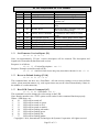
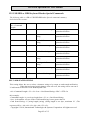
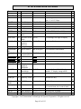
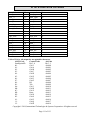
Revision History
Revision
50
A
B
C
Date
05/07/2012
08/06/2012
12/30/2012
5/5/2013
05/08/20133/14/2014
Description of Changes
Initial draft
Initial release
Updated Appendix A
Remove the TTL part
Remove conformal coated PCA from features
enumeration SN and special terminator CRLF
Clarify config 1C setting bits
Correct Original and Enhanced Encryption Format
Added Encryption Field 8 and 9 definitions
Updated HID block Size
NGA flag added to Status report 2 byte
Added Raw track prefix or sync char if KB mode
Corrected PID for standard and secure HID/HIDKB
By
Jenny W
Jenny W
Bruce K
C.H.
Bruce K
Copyright © 2014, International Technologies & Systems Corporation. All rights reserved.
Page 3 of 113
ID TECH Spectrum Air User Manual
1
2
3
4
5
6
7
8
9
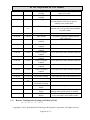
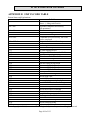
Table of Contents
INTRODUCTION ........................................................................................................... 7
FEATURES .................................................................................................................... 8
ABBREVIATIONS ......................................................................................................... 9
RELATED DOCUMENTS ............................................................................................ 11
INSTALLATION .......................................................................................................... 12
5.1
RS232 Interface .................................................................................................. 12
5.2
USB CDC Interface ............................................................................................ 12
5.3
USB HID Interface ............................................................................................. 12
5.4
USB HID Keyboard Interface .............................................................................. 12
OPERATION ................................................................................................................ 13
6.1
Operating Procedure ........................................................................................... 13
6.2
Standard Mode (Automatic Transmit) ................................................................... 13
6.3
Buffered Mode ................................................................................................... 13
SPECIFICATION ......................................................................................................... 15
CONNECTOR PINOUT ................................................................................................ 17
COMMAND PROCESS ................................................................................................ 19
9.1
Communication Structure .................................................................................... 19
9.1.1 MOIR Protocol for Sending Commands and Receiving Responses ............................ 19
9.1.2 Sending Command ............................................................................................... 19
9.1.2.1
Protocol ........................................................................................................ 19
9.1.2.2
Example of LRC Calculation .......................................................................... 20
9.1.2.3
Communication Timing .................................................................................. 20
9.2
NGA Protocol for Sending Commands and Receiving Responses ............................ 20
9.3
General Reader Commands Description ................................................................ 21
9.3.1 Get Firmware Version Report [39] ......................................................................... 22
9.3.2 Revert to Default Settings [53 18] .......................................................................... 22
9.3.3 Host LED Control Command [6C] ......................................................................... 22
9.3.4 Reader Reset Command [49] ................................................................................. 23
9.3.5 Get Copyright Information [38] ............................................................................. 23
9.4
Reader Configuration Commands Description ....................................................... 23
9.4.1 Restore Configuration Settings to Default [53 18] .................................................... 24
9.4.2 Read All Configuration Settings [52 1F] ................................................................. 25
9.4.3 Bit Setting and Clearing Commands ....................................................................... 26
9.4.4 Read Specific Configuration Setting [52 nn]............................................................ 26
9.4.5 Read Reader Serial Number [52 4E] ....................................................................... 26
9.4.6 Set Reader Serial Number [53 4E] .......................................................................... 27
9.4.7 Buffered Mode Arm to Read Command [50 01 30] .................................................. 27
9.4.8 Buffered Mode MSR Reset Command [50 01 32] .................................................... 27
9.4.9 Buffered Mode Read MSR Data Command [51 01 XX] ........................................... 28
9.4.10 MSR Configuration Commands Description............................................................ 28
9.4.11 Set MSR Transmit Mode [53 1A] ........................................................................... 29
9.4.12 Set MSR Read Direction [53 1D] ........................................................................... 29
Copyright © 2014, International Technologies & Systems Corporation. All rights reserved.
Page 4 of 113
ID TECH Spectrum Air User Manual
9.4.13 Set MSR Send Option [53 19]................................................................................ 29
9.4.14 Set MSR Data Terminator [53 21] .......................................................................... 30
9.4.15 Set MSR Data Prefix String [53 D2] ....................................................................... 31
9.4.16 Set MSR Data Postfix String [53 D3] ..................................................................... 31
9.4.17 Set Track 1 ID [53 31] .......................................................................................... 31
9.4.18 Set Track 2 ID [53 32] .......................................................................................... 31
9.4.19 Set Track 3 ID [53 33] .......................................................................................... 31
9.4.20 Set Track Selection [53 13] ................................................................................... 32
9.4.21 Set Track Separator [53 17] ................................................................................... 32
9.4.22 Set Track n Prefix [53 34] ..................................................................................... 32
9.4.23 Set Track n Suffix [53 37] ..................................................................................... 33
9.5
Magnetic Card Read Modes ................................................................................. 33
9.6
LED Handling .................................................................................................... 34
9.7
Card Status Notification [B0 xx] .......................................................................... 34
9.8
Key Loading Command ...................................................................................... 35
9.9
Set OPOS/JPOS Command .................................................................................. 36
9.10
Read MSR Options Command ............................................................................. 36
10
SECURITY FEATURES ............................................................................................... 38
10.1
Encryption Management...................................................................................... 39
10.2
Check Card Format ............................................................................................. 39
10.3
MSR Data Masking ............................................................................................ 39
10.4
Output Format .................................................................................................... 40
10.4.1 Data Format ......................................................................................................... 40
11
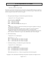
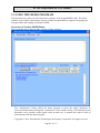
USING THE DEMO PROGRAM ................................................................................... 45
11.1
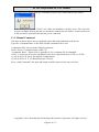
Manual Command .............................................................................................. 46
11.2
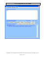
Security Level 3 Decryption ................................................................................ 48
11.3
Security Level 4 Features and Decryption ............................................................. 50
11.4
Reader Operations .............................................................................................. 53
12
Decryption Examples ..................................................................................................... 54
13
USB DATA FORMAT .................................................................................................. 59
13.1
USB Level 1 and level 2 Standard Mode Data Output Format ................................. 59
13.1.1 USB HID Data Format .......................................................................................... 60
13.1.2 Descriptor Tables ................................................................................................. 60
13.2
USB Level 1 and level 2 POS Mode Data Output Format ....................................... 63
13.3
Level 3 Data Output Format ................................................................................ 66
13.4
Level 4 Data Output Format ................................................................................ 68
13.5
Level 4 Activate Authentication Sequence ............................................................ 70
13.6
General Commands ............................................................................................. 73
13.7
RS232 Reader Special Configuration Commands ................................................. 78
13.8
USB HID Keyboard Reader Special Commands .................................................... 81
13.9
USB HID or HID Keyboard Reader Special Commands ......................................... 82
14
MAGNETIC STRIPE READER CONFIGURATION ....................................................... 86
15
USB HID KB DATA OUTPUT FORMAT ...................................................................... 90
15.1
Level 1 and level 2 POS Mode Data Output Format ............................................... 90
15.2
Level 3 Data Output Format ................................................................................ 92
Copyright © 2014, International Technologies & Systems Corporation. All rights reserved.
Page 5 of 113
ID TECH Spectrum Air User Manual
15.3
Level 4 Data Output Format ................................................................................ 92
15.4
Level 1 and 2 Buffer Mode Output Format ............................................................ 94
15.5
Level 4 Activate Authentication Sequence ............................................................ 95
APPENDIX A Setting Parameters and Values ........................................................................ 99
APPENDIX B STATUS CODE TABLE............................................................................... 104
APPENDIX C Key Code Table in USB Keyboard Interface ................................................... 106
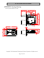
APPENDIX D Envelope Drawing ....................................................................................... 113
Copyright © 2014, International Technologies & Systems Corporation. All rights reserved.
Page 6 of 113
ID TECH Spectrum Air User Manual
1 INTRODUCTION
The Spectrum Air outdoor insert reader is designed for installations that might be subjected to
harsh environments such as fuel pumps and outdoor kiosks. This insert reader meets IP 65 rating
with dual head configurations supporting up to 3 tracks of information from ISO and AAMVA
encoded cards. A card is read by inserting it into and/or removing it out of the card slot. The
Spectrum Air utilizes TriMag III and offers encryption feature for USB and RS232 interface.
Copyright © 2014, International Technologies & Systems Corporation. All rights reserved.
Page 7 of 113
ID TECH Spectrum Air User Manual
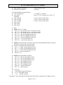
2 FEATURES
-
Dual Head Magnetic only insert reader
Interface: USB/KB, USB/HID, USB/CDC, RS232
IP 65 rating
Reads up to 3 tracks of card data
Sealed bezel and chassis – meaning that unit can allow water ingress but not allow water
to seep into the host unit
Ideal for gas pumps and outdoor kiosk applications
TDES / AES encryption
DUKPT key management
Card seated switch
OPOS & JPOS support
Support all software features current SPT MOIR supports
1 year Warranty
Gas pump mounting – compatible with UIC/Panasonic mounting
Mounting: Compatible with Panasonic ZU-1870MA8T2
Copyright © 2014, International Technologies & Systems Corporation. All rights reserved.
Page 8 of 113
ID TECH Spectrum Air User Manual
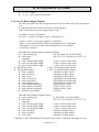
3 ABBREVIATIONS
AAMVA
American Association of Motor Vehicle Administration
ABA
American Banking Association
ACK
Acknowledge
AES
Advanced Encryption Standard
ASIC
Application Specific Integrated Circuit
BPI
Bits per Inch
CADL
California Drivers License Format (obsolete)
CE
European Safety and Emission approval authority
COM
RS232 serial communication port
CTS
Clear-To-Send
CBC
Cipher-block chaining
CDC
USB to serial driver (Communication Device Class)
DC
Direct Current
DES
Data Encryption Standard
DUKPT
Derived Unique Key per Transaction
DMV
Department of Motor Vehicle
ESD
Electro-Static Discharge
ETX
End of Transmission
FPC
Flexible Printed Circuit
FCC
Federal Communications Commission
GND
Signal Ground
Hex
Hexadecimal
HID
Human Interface Device
IPS
Inches per Second
ISO
International Organization for Standardization
JIS
Japanese Industrial Standard
JPOS
Java for Retail Point of Sale
KB
Keyboard
KSN
Key Serial Number
LED
Light Emitting Diode
LRC
Longitudinal Redundancy Check Character.
LSB
Least significant Bit
mA
Milliamperes
MAC
Message Authentication Code
MSB
Most significant Bit
msec
Milliseconds
MSR
Magnetic Stripe Reader
mV
Millivolts
NACK
Non-acknowledge
NGANext Generation ArchatectureOLE Object Linking and Embedding
OPOS
OLE for Retail Point of Sale
OTP
One Time Programmable
PAN
Primary account number
PCA
Printed Circuit Board (Assembled)
PCB
Printed circuit board bare.
PCI
Payment Card Industry
Copyright © 2014, International Technologies & Systems Corporation. All rights reserved.
Page 9 of 113
ID TECH Spectrum Air User Manual
POH
Powered On Hours
POS
Point of Sale
PPMSR
Serial Port Power Magstripe Reader
P/N
Part Number
PS/2
IBM Personal System/2 Keyboard Interface
RoHS
Restriction of Hazardous Substances
RTS
Request To Send
SHA-1
Enhance Cryptographic Hash Function
SPI
Serial Peripheral Interface
T1, T2, T3
Track 1 data, Track 2 data, Track 3 data
TDES
Triple Data Encryption Standard
USB
Universal Serial Bus
UV
Ultra Violet – spectrum of light rays
Note: many unusual words used in this document are defined in the Function ID table on
page.
Formatting to designate certain data types
‘A’
41h
41
“String”
Default
<ETX>
6913
[xxx … xxx]
[52 4E]
B0
A single character in ASCII
A single character in hexadecimal
A single character in a group of hexadecimal digits
ASCII character group if in communication group, not NULL terminated.
A default value will be bolded
A communication member, one byte in size, except the message length.
four-digit hex numbers are error status indications
Square brackets designate optional or repeated data groupings
Bold square brackets in headings are the key communication bytes for a
particular command
bit positions are all from position 0 to position 7 so if only B1 is set the value of
a byte is 02h.
Copyright © 2014, International Technologies & Systems Corporation. All rights reserved.
Page 10 of 113
ID TECH Spectrum Air User Manual
4 RELATED DOCUMENTS
ISO 7810
Identification Cards - Physical Characteristics (1995)
ISO 7811
Identification Cards -Recording Technique (1995)
AAMVA
Best Practices Guidelines for the Use of Magnetic Stripes
ISO 4909
Magnetic stripe content for track 3
ISO 7812
Identification Cards – Identification for issuers Part 1 & 2
ISO 7813
Identification Cards – Financial Transaction Cards
ANSI X9.24-2002
Retail Financial Services Symmetric Key Management
USB ORG
USB Specification Rev. 2.0
Supported Programs
Secure MOIR RS232 Demo Program
Secure MOIR USB Demo Program
Secure MOIR Configuration Program
Copyright © 2014, International Technologies & Systems Corporation. All rights reserved.
Page 11 of 113
ID TECH Spectrum Air User Manual
5 INSTALLATION
5.1 RS232 Interface
The reader is plugged into a DB9 connector on the host computer and the 5-volt power supply
connected to the DC connector on the backside of the DB9 connector.
As a standard serial interface, the host must be configured to accept the data and perform the
appropriate processing. For the RS232 interface device, the host application's RS-232
parameters (baud rate, Start/Stop characters, parity, and handshaking method) need to match
those expected by the reader. The reader by default communicates at 38.4K BAUD, 8-bit, no
parity, and 1-stop bit. The magnetic reader's output can be formatted with terminating characters
and special preamble and/or postamble character strings to match the data format expected by
the host.
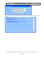
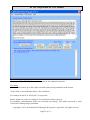
5.2 USB CDC Interface
Plug the reader into a standard USB connector on the host computer. The “found new
hardware” screen would pop up. Follow the prompts and install the USB CDC driver
80066803-004 Sftw;USBCDC inf;MM2;SM;MOIR;HIR;Win7. After the USB CDC driver is
installed, the reader would be a virtual COM device.
5.3 USB HID Interface
Plug the reader into a standard USB connector on the host computer. The reader gets all needed
power through the USB connector. The host will receive data from the reader as if it is coming
from a USB HID device. The host must be configured and be running an application ready to
accept and process the data from the reader.
5.4 USB HID Keyboard Interface
Plug the reader into a standard USB connector on the host computer and it should be ready to
operate. The reader gets all needed power through the USB connector. The host will receive
data from the reader as if it is coming from a USB keyboard.
Copyright © 2014, International Technologies & Systems Corporation. All rights reserved.
Page 12 of 113
ID TECH Spectrum Air User Manual
6 OPERATION
6.1 Operating Procedure
The Spectrum Air is easy to operate. Make sure the reader is properly connected and receiving
sufficient power. The green LED will indicate that it is ready to read. After a card is read, the
green LED will light if the read was good and after a bad card read, the red LED will light for
half a second. Note the LED changes immediately after the MSR is read in auto mode, but not
until the host requests MSR in buffered mode (in normal operation these should be similar).
The LED will be dark (that is off) when the MSR is being processed.
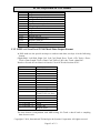
LED INDICATION
MEANING (LED controlled by reader)
Solid Amber
Solid Green
Slow Flash Green
Red for half second
Off
Reader has not connected properly to the host.
Reader is ready to read a magnetic stripe, or is idle.
Reader is in buffered mode, but has not been armed to read.
Bad magnetic stripe read.
Reader is decoding magnetic stripe data.
By default, the LED is under the control of the reader. The LED can also be under the control of
the host application. If the LED is under the control of the host, the following settings are
available:
● Turn the LED off (dark)
● Turn on the LED green, red or amber
● Set the LED flashing green, red or amber
● Set the LED slow flashing green, red or amber
6.2 Standard Mode (Automatic Transmit)
To read a Magnetic Stripe Card, follow these simple steps:
1. Insert the card into the reader until it hits a hard stop.
2. Withdraw the card in one continuous motion. The green LED will go off briefly. (The reader
by default reads the card on insert and on withdrawal and combines these reads, but only
sends the track data after withdrawal.)
3. When the card has been fully withdrawn, the LED will turn red (to indicate a bad read) or
to green (to indicate a good read). The track data is automatically sent to the host.
6.3 Buffered Mode
This is more complicated than standard mode, see the suggested steps for buffered more
application below.
When the unit is armed to read in buffer mode, decoded data is retained in reader memory and
an optional notice is sent to the host to indicate its presence. Data is held in memory until the
reader receives the next ARM TO READ or MSR RESET command, at which point all data in
memory will be erased. Please refer to the specific Buffered Mode Arm to Read Command [50
01 30] page 27ARM TO READ IN BUFFER MODE, MSR RESET IN BUFFER MODE, and
Copyright © 2014, International Technologies & Systems Corporation. All rights reserved.
Page 13 of 113
ID TECH Spectrum Air User Manual
READ MSR DATA IN BUFFER MODE commands. In buffered mode, the LED is set to slow
flashing green until the reader is armed to read then it turns solid green. It remains green when
the card track data is captured. When the host requests the buffered data the LED will briefly
go dark during track decode then return to slow flashing green if the read was successful or
turn red for .5 second if the read was unsuccessful, it will remain at slow flashing green until it
is rearmed. In normal operation the host will arm to read before the patron tries to use the
reader and will request the card track data immediately after the card is read so the LED will be
green for a successful read or red for an unsuccessful read. It will then revert to solid green
because the host immediately arms the reader to read the next card.
Suggested steps for buffered mode application:
1. Set reader to buffered mode (It only needs to be set once; use Configurator software, not
in regular application; the result will be stored in EEPROM).
53 1A 01 32
The LED will turn to a slow green flash.
2. Arm to read
50 01 30
The LED will turn green indicating okay to read a card.
3. Prompt the user to insert and remove a card
The LED will stay green but card track data was captured.
The reader by default will send out the card inserted, card removed and mag data present
statuses.
The host can discover the state of the reader by one of two methods, the host can wait for
the reader to report that it has mag data buffered (from the mag data present status) then
request that data or the host can poll the reader for the track data.
4. Poll for Read Buffered Data
51 01 30 for any track data (Or 51 01 3X if one requires specific track data)
The LED will turn off while the card track data is processed.
The LED will turn RED for .5 seconds if any of the required tracks were bad or there was
data on an optional track that did not decode properly. The LED will turn slow flashing
green otherwise. The LED will hold this setting until the reader is rearmed or put into
auto mode.
5. Process the data.
6. Display proper notification to user.
7. Go back to step 2 for next read.
Copyright © 2014, International Technologies & Systems Corporation. All rights reserved.
Page 14 of 113
ID TECH Spectrum Air User Manual
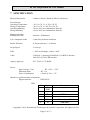
7 SPECIFICATION
Physical dimensions
: 120mm x 92mm x 48mm (LxWxH with bezel)
Environments
Operating Temperature
Storage Temperature
Operating humidity
Storage humidity
: -20 °C to 70 °C (-4 °F to 158 °F)
: -40 °C to 70 °C (-40 °F to 158 °F)
: 10% to 90% (no condensation allowed)
: 10% to 90% (no condensation allowed)
Magnetic Reading
Reading direction
: Insertion / Withdrawal
Life of magnetic heads
: 1,000,000 operations minimum
Media Thickness
: 0.76mm (tolerance +- 0.08mm)
Swipe Speed
: 3 to 60 ips
ESD
: +- 8kV air discharge, contact +-4kV
Cable
: CAB1041-1 (drawing PN 80028211) for RS232 interface
80035212-002 for USB interface
Agency Approval
: FCC Class A, CE, RoHS
Power:
Input Voltage (Vin)
Maximum Input
Power Consumption
: DC +4.5V~ +5.5V
: DC +6V
: < 20mA @ Vin = +5V
Interfaces, signals and main components:
Support interface
: USB, RS232
: USB
P1
1
Description
Chassis Ground
2
3
4
5
Signal
Chassis
GND
-D+
-Vin
6
D-
USB Data -
-USB Data +
-Power Input: 5V
Copyright © 2014, International Technologies & Systems Corporation. All rights reserved.
Page 15 of 113
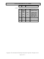
ID TECH Spectrum Air User Manual
7
GND
Power Ground
P1
1
Direction
--
Description
Chassis Ground
2
Signal
Chassis
GND
TXD
OUT
3
RXD
IN
4
5
Vin
--
---
Transmit Data:
RS232 Signal
Receive Data:
RS232 Signal
Power Input: 5V
--
6
--
--
--
7
GND
--
Power Ground
: RS232
Copyright © 2014, International Technologies & Systems Corporation. All rights reserved.
Page 16 of 113
ID TECH Spectrum Air User Manual
8
CONNECTOR PINOUT
RS232 Interface
Cable part number: CAB1041-1 (drawing PN 80028211)
Wire
Connection
J1
1
2
3
4
5
6
7
Signal
Chassis GND
TXD
RXD
Vin
RTS
CTS
GND
P1
SHELL
2
3
8
7
5
P2
-
PIN
SLEEVE
PCA PIN Assignment
P1
1
Signal
CHASSIS GND
2
3
4
5
6
7
TXD
RXD
Vin
--GND
P2
Magnetic Head
Signal
T1A
FPC Interface
1
Description
Magnetic head input A (+)
track 1
Copyright © 2014, International Technologies & Systems Corporation. All rights reserved.
Page 17 of 113
ID TECH Spectrum Air User Manual
2
T1B
3
T2A
4
T2B
5
T3A
6
T3B
7
Chassis GND
Magnetic head input B (-)
track 1
Magnetic head input A (+)
track 2
Magnetic head input B (-)
track 2
Magnetic head input A (+)
track 3
Magnetic head input B (-)
track 3
Power Ground
LED Interface
LED1
1
2
3
Signal
Red
GND
Green
Copyright © 2014, International Technologies & Systems Corporation. All rights reserved.
Page 18 of 113
ID TECH Spectrum Air User Manual
9 COMMAND PROCESS
9.1 Communication Structure
This section defines the command format for communicating with the reader.
9.1.1 MOIR Protocol for Sending Commands and Receiving Responses
Every command and response follows the same basic structure:
HEADER
DATA
TRAILER
The HEADER consists of <60> followed by <Command Length> the command length is two
bytes: most significant then least significant byte; The DATA often consists of the
command ID, Function ID, Function Length, and Function Data The TRAILER consists of
<LRC> followed by <ETX>. The maximum size of length is 768 (plus envelope bytes).
9.1.2 Sending Command
60<Length><Command ID>[<FuncID><Len><FuncData>…]<LRC><ETX>
Where:
<Length> = is a two-byte count of the bytes in the DATA field.
<Command ID> = is a one byte value identifying a specific command ID.
<FuncID> = is a one byte Function ID, which identifies the particular function or settings
affected
<Len> = is a one-byte length count for the data block “<FuncData>”
<FuncData> = is the data block for the function
<LRC> = See Calculation below
<ETX> = 03
9.1.2.1 Protocol
Host
Command
Response
Reader
Status
60 <Length> [<Response Data>] <Status> <LRC><ETX>
Where:
<Length> = is a two-byte counter from <Response Data> to the end of <Status>.
<Response Data> = is the data block associated with the Response.
<Status> is a two-byte value indicating the success or failure of a command.
The overall LRC (Modulus 2 = Exclusive OR) checksum (from 60 to LRC) should be zero. See
example of LRC calculation in the next section.
Copyright © 2014, International Technologies & Systems Corporation. All rights reserved.
Page 19 of 113
ID TECH Spectrum Air User Manual
9.1.2.2 Example of LRC Calculation
LRC = Longitudinal Redundancy Check. Calculated by taking ‘Exclusive OR’ (Modulus 2) of all
characters preceding it, total with LRC is equal to zero.
For example, the following command means "Set <Send Option> to 0x30 value”.
<60><00><04><53><19><01><30><1F><03>
<1F> is the LRC character.
It is derived from the following:
Characters
<60>
<00>
<04>
<53>
<19>
<01>
<30>
<1F>
#1(binary)
0110
0000
0000
0101
0001
0000
0011
0001
#2 (binary)
0000
0000
0100
0011
1001
0001
0000
1111 <Result of Exclusive OR>
9.1.2.3 Communication Timing
Maximum delay for the reader to respond to a write configuration command is 20ms. Typical
delay is 5ms.
During the command processing time, the reader will not respond to a new command. The reader
will accept a new command as soon as it has responded to the previous command.
Note: Maximum delay between two characters in a command is 100ms.
During command processing or the reading of a magnetic stripe, the reader will not respond to a
new command. The typical delay for the reader to respond to a setting command is less than
20ms.
Once communication between the host and the reader has been established, sending the
appropriate setup commands to the reader from the host application can enter changes into the
reader’s settings.
Following are explanations and examples of the proper format and command content to send
commands to the reader. All commands and characters are expressed in hex format and
contained in brackets.
9.2 NGA Protocol for Sending Commands and Receiving Responses
Spectrum Air also supports NGA protocol, a second protocol which is compatible with
SecureMag readers. All the command can be sent with a different envelope as described below:
Setting Command
Copyright © 2014, International Technologies & Systems Corporation. All rights reserved.
Page 20 of 113
ID TECH Spectrum Air User Manual
The setting data command is a collection of many function setting blocks and its format
is as follows.
Command: <STX><S><FuncSETBLOCK1>…<FuncBLOCKn><ETX><LRC>
Response: <ACK> or <NAK> for wrong command (invalid funcID, length and value)
Each function-setting block <FuncSETBLOCK> has following format:
<FuncID><Len><FuncData>
Where:
<FuncID> is one byte identifying the setting(s) for the function.
<Len> is the length count for the following function-setting block <FuncData>.
<FuncData> is the current setting for this function. It has the same format as in the
sending command for this function.
Get Setting Command
This command will send current setting to application.
Command: <STX> <R> <FuncID> <ETX> <LRC 1>
Response: <ACK> <STX> <FuncID> <Len> <FuncData> <ETX> <LRC 2>
<FuncID>, <Len> and <FuncData> definition are same as described above.
Where:
Characters
<STX>
<ETX>
<ACK>
<NAK>
<UnknownID>
<AlreadyInPOS>
Hex Value
02
03
06
15 for
RS232 and
USB HID
interface;
FD for USB
KB interface
16
17
<R>
<S>
<LRC>
52
53
-
Description
Start of Text
End of Text
Acknowledge
Negative Acknowledge
Warning: Unsupported ID in setting
Warning: Reader already in OPOS
mode
Review Setting
Send Setting
Xor’d all the data before LRC.
9.3 General Reader Commands Description
Reader Command Summary
Copyright © 2014, International Technologies & Systems Corporation. All rights reserved.
Page 21 of 113
ID TECH Spectrum Air User Manual
ASCII
‘8’
‘9’
‘$’
HEX
38
39
24
Name
Copyright Report
Firmware Version Report
Get Reader Status
‘F’
46
Key Loading
‘I’
49
Reader Reset
‘M’
4D
OPOS/ JPOS Command
‘P’
50
Arm/Disarm to Read
‘Q’
51
Read Buffered Data
‘R’
52
Read Reader Options
‘S’
53
Set Reader Options
‘l’
6C
LED Functions
Table 1 – Reader Command Summary
Use
Requests reader’s copyright notice
Requests version string
Determining card inserted, MSR data
present, etc.
Special command to load encryption
keys
Reset the reader. Software reset does
not resend startup string
Command to enter OPOS or JPOS
mode
Arm to Capture Buffer Mode MSR
Read Stored MSR Data
Read various reader optional settings
Set various reader optional functions
Turning on/off/flash the bicolor-LED
9.3.1 Get Firmware Version Report [39]
60 00 01 39 58 03
Note: An approximately ‘55-byte’ version description will be returned. The description and
length varies somewhat by hardware and version.
Response is as follows:
60 00 35 <Version Description> LRC 03
Response Example (mixed hex and ASCII):
60 00 35 "ID TECH TM3 Secure Mag Only Insert RS232 Reader V1.00" 63 03
9.3.2 Revert to Default Settings [53 18]
60 00 02 53 18 29 03
This command does not have any <FuncData>. All non-security settings revert to their default
values. (Some transient statuses e.g. card report timers may not be cleared immediately if done in
the middle of a card transaction).
9.3.3 Host LED Control Command [6C]
60 00 02 6C <LED State> LRC 03
This command is used to change the color setting on the LED.
Note: Reader must have the “LED” option on the reader for this command function properly.
Where <LED State> are:
‘0’
30
LED will be turned off.
‘1’
31
LED will be turned on green.
‘2’
32
LED will be turned on red.
‘3’
33
LED will be turned on amber.
‘4’
34
LED will be flashing red/amber.
‘5’
35
LED will be flashing green.
‘6’
36
LED will be flashing red.
‘7’
37
LED will be flashing amber.
Copyright © 2014, International Technologies & Systems Corporation. All rights reserved.
Page 22 of 113
ID TECH Spectrum Air User Manual
‘A’
41
LED will be slowly flashing green
‘B’
42
LED will be slowly flashing red
‘C’
43
LED will be slowly flashing amber
Example: To flash the LED green:
60 00 02 6C 35 3B 03
Command completed successfully response 9000 is as follows:
60 00 02 90 00 F2 03
Other possible response statuses:
6913 2nd byte of LED command was not 30-37, or 41-43
691D Command length is incorrect
691F host LED control not enabled. To configure the reader to support host see bit 4 in
set reader option section 11.6.
9.3.4 Reader Reset Command [49]
60 00 01 49 28 03
This allows the host to return the reader to its default state, i.e. not armed to read, no magnetic
data stored, etc. The reader remains on-line. This command is not supported on USB interface
reader.
Command completed successfully response 9000 is as follows:
60 00 02 90 00 F2 03
9.3.5 Get Copyright Information [38]
60 00 01 38 59 03
An approximately ‘26-byte’ Copyright Notice will be returned.
Response is as follows:
60 00 3F <Copyright String> LRC 03
Response Example mixed hex and ASCII:
60 00 3F Copyright (c) 2011, ID TECH LRC 03
9.4 Reader Configuration Commands Description
For RS232 device, the serial communication parameter default setting is 38400, none, 8, 1.
Setting Command
Command requests and responses are sent to and received from the device. For USB interface
devices, the commands are sent to the device using HID class specific request Set_Report (21 09
…). The response to a command is retrieved from the device using HID class specific request
Get_Report (A1 01 …). These requests are sent over the default control pipe. For RS232
interface devices, please see the commands listed below.
COMMANDS
The following table is a magnetic stripe reader commands summary described in this section:
HEAD
DATA
NAME
USAGE
Copyright © 2014, International Technologies & Systems Corporation. All rights reserved.
Page 23 of 113
ID TECH Spectrum Air User Manual
60 00 04
53 13 01 xx
60 00 04
5317 01 xx
60 00 04
5319 01 xx
60 00 04
53 1A 01
xx
MSR Reading
60 00 04
60 00 04
53 1D 01
53 xx
60 01
Decoding Method
LRC Option
60 00 04
53 61 01
60 00 04
53 62 01
60 00 04
53 63 01
60 00 04
53 64 01
60 00 04
53 65 01
60 00 04
53 66 01
60 00 04
53 67 01
60 00 04
53 68 01
60 00 04
53 69 01
Track1 7bit start
sentinel
Track1 6bit start
sentinel
Track1 5bit start
sentinel
Track2 7bit start
sentinel
Track2 5bit start
sentinel
Track3 7bit start
sentinel
Track3 6bit start
sentinel
Track3 5bit start
sentinel
Track end sentinel
60 00 04
53 21 01 xx
Terminator Setting
60 00 04
53 3n 01 xx Track 1,2, 3 ID Setting
To edit the data read from the card
xx
53 Dx xx
Preamble and
To edit the data read from the card
Postamble Settings
50 01 30 Arm to Read in Buffer To enable reading in the buffer mode
Mode
50 01 32 MSR Reset in Buffer
To return the reader to its default
Mode
settings when buffer mode is enabled
51 01 xx
Read MSR Data in To set the tracks on the magnetic stripe
Buffer
to be read while in the buffer mode
Mode
60 00 xx
60 00 03
60 00 03
60 00 03
Track Selection
Setting
Track Separator
Setting
Send Option
To select the tracks on the magnetic
stripe to be read
To format the data read from the card
To enable or disable the sentinel or
account number on Track 2 only or
sending error notification
To turn the magnetic stripe reading
function off or on in either auto-transmit
or buffer mode
To read a card in a selected direction
To enable or disable sending out the
LRC character
To set the track1 start sentinel character
To set the track1 start sentinel character
To set the track1 start sentinel character
To set the track2 start sentinel character
To set the track2 start sentinel character
To set the track3 start sentinel character
To set the track3 start sentinel character
To set the track3 start sentinel character
To set the track end sentinel character
To format the data read from the card
9.4.1 Restore Configuration Settings to Default [53 18]
60 00 02 53 18 29 03
Copyright © 2014, International Technologies & Systems Corporation. All rights reserved.
Page 24 of 113
ID TECH Spectrum Air User Manual
This command restores most settings to their default value.
Note: Executing this command does not affect the security settings, the factory
options or the serial number (page 27).
Command completed successfully response 9000 is as follows:
60 00 02 90 00 F2 03
9.4.2 Read All Configuration Settings [52 1F]
60 00 02 52 1F 2F 03
This command does not have any <FuncData>. It retrieves all current settings.
The MOIR reader sends back a <Response>.
<Response> format:
The current configuration data block is a collection of many Function-Setting
blocks <FuncSETBLOCK> as follows:
60 <Length> <FuncSETBLOCK1>…<FuncSETBLOCKn> LRC 03
Each Function-Setting block <FuncSETBLOCK> has the following format:
<FuncID> <Len> <FuncData>
Where:
<Length> is a two bytes counter, which indicates bytes of all
<FuncSETBLOCK>. The most significant byte comes first.
<FuncID> is a one byte Function ID identifies the setting(s) for the function. For a
complete list of FuncID, see Appendix A, page 99.
<Len> is a one-byte length count for the following function-setting block
<FuncData>.
<FuncData> is the current setting for this function. It has the same format as in the
Sending Command for this function. See SENDING COMMAND LIST
for details.
<FuncSETBLOCK> are in the order of their function ID <FuncID>.
Example:
60 00 B7
00 00 77
01 01 17
01 0D 24
00 37 00
01 30 44
01 03 4B
01 31 60
01 3B 66
01 3B 6E
00 D3 00
23
01
01
01
35
01
01
01
01
01
58
01
03
0D
30
00
30
2A
30
25
2B
01
30
7E
19
2F
38
45
4D
61
67
7B
31
4C
01
01
01
00
01
01
01
01
01
CD
01
34
31
00
36
30
30
25
21
30
03
31
10
1A
31
00
47
50
62
68
84
4E
01
01
01
39
01
01
01
01
01
09
30
31
00
00
11
30
25
3B
08
08
11
1B
32
41
48
55
63
69
85
00
01
01
01
01
01
01
01
01
01
00
8F
30
00
37
13
30
3B
3F
31
00
13
1D
33
42
49
5C
64
6C
86
00
01
01
01
01
01
01
01
01
01
00
30
33
00
30
06
37
25
25
07
00
14
21
34
43
4A
5D
65
6D
D2
Example Interpreted:
60 00 B7
ACK, length data: 00B7 hex or 183 decimal.
23 01 30
Copyright © 2014, International Technologies & Systems Corporation. All rights reserved.
Page 25 of 113
ID TECH Spectrum Air User Manual
4C 01
4E 09
...
10 01
11 01
...
CD 03
31
08 00 00 00 00 00 00 00 00
20
8F
LRC, ETX.
9.4.3 Bit Setting and Clearing Commands
This is a special type of setting command. For an 'S' (53) command that is setting only
one configuration byte, the first byte of the command (the 'S' or 53) can be replaced with
a '0' (31) to clear individual bits or a '1' (31) to set individual bits without changing the
other bits in that configuration byte. These commands allows one to set or clear one or
more bits of a configuration setting.
A command to clear one bit of a configuration setting is ‘0’.
Example:
30 30 01 80 will clear the highest bit in configuration byte 10
31 30 01 80 will set the highest bit in configuration byte 10
31 30 01 81 will set the lowest and highest bits of configuration byte 10
This simplifies the setting commands for those not familiar with hexadecimal values;
there is no need to read the setting before writing the setting; and it reduces the chance
of changing another setting when setting a bit value.
Limitations
It can only be used on a one byte configuration setting.
This cannot be used on special fields like the security level, that is no 30 7E 01
02
This cannot be used to simultaneously turn some bits on and some bits off, so no
changing 31 to 32 which is necessary to change TDES to AES.
9.4.4 Read Specific Configuration Setting [52 nn]
60 00 02 52 <Configuration> LRC 03
The <Configuration> byte corresponds to the byte from a specific configuration value.
All MSR reader Read Configuration Commands are listed in the following format:
60 00 02 52 <FuncID> LRC 03
For example to read the “Card Option” configuration, send
60 00 02 52 10 20 03
9.4.5 Read Reader Serial Number [52 4E]
60 00 02 52 4E 7E 03
Note: An ‘8 to 10-byte’ string of serial number will be returned.
Response is as follows:
60 00 0B 4E 09 08 <Serial Number (8 bytes)> LRC 03
Serial number can be 8 to 10 characters
60 00 0D 4E 0B 0A <Serial Number (10 bytes)> LRC 03
Copyright © 2014, International Technologies & Systems Corporation. All rights reserved.
Page 26 of 113
ID TECH Spectrum Air User Manual
9.4.6 Set Reader Serial Number [53 4E]
60 00 0C 53 4E 09 08 <Serial Number (8 bytes)> LRC 03
Serial Number is an eight to ten-byte field containing the serial number in ASCII.
Example:
60 00 0C 53 4E 09 08 31 32 33 34 35 36 37 38 78 03
Note the byte following the 4E is serial number length +1, then the serial number length.
Command completed successfully response 9000 is as follows:
60 00 02 90 00 F2 03
9.4.7 Buffered Mode Arm to Read Command [50 01 30]
60 00 03 50 01 30 02 03
This command enables the MSR to be ready to capture a card insertion and/or removal in
buffered mode.
Any previously read data will be erased and reader will wait for the next insertion or removal.
As the user inserts or removes a card, the data will be saved, but will not be sent to the host. The
reader holds the data until receiving the next “Arm to Read” or “MSR Reset” command.
A notification will be sent to inform host of magnetic data presence after user card insertion
and/or removal if the corresponding bit in Reader Option byte has been set. See section 11.6.
Successful response is as follows:
60 00 02 90 00 F2 03
Problem response is as follows:
E0 00 02 xxxx LRC 03
Other possible response statuses:
6912 'P' command length must be 1
6916 'P' command data must be 0x30 or 0x32
6920 Reader not configured for buffered mode
6922 Reader not configured for magstripe read
9.4.8 Buffered Mode MSR Reset Command [50 01 32]
60 00 03 50 01 32 00 03
This command will disable MSR read and clear any magnetic data in buffered mode. The reader
enters to a disarmed state and will ignore MSR data.
Successful response is as follows:
60 00 02 90 00 F2 03
Problem response is as follows:
E0 00 02 xxxx LRC 03
Other possible response statuses:
6912 'P' command length must be 1
6916 'P' command must be 0x30 or 0x32
6920 Reader not configured for buffered mode
6922 Reader not configured for magstripe read
Copyright © 2014, International Technologies & Systems Corporation. All rights reserved.
Page 27 of 113
ID TECH Spectrum Air User Manual
9.4.9 Buffered Mode Read MSR Data Command [51 01 XX]
60 00 03 51 01 <Track Selection Option> LRC 03
The <Track Select Option> byte is defined as follows:
‘0’
Any Track
‘1’
Track 1
‘2’
Track 2
‘3’
Track 1 and Track 2
‘4’
Track 3
‘5’
Track 1 and Track 3
‘6’
Track 2 and Track 3
‘7’
Track 1, Track 2 and Track 3
‘8’
Track 1 and/or Track 2
‘9’
Track 2 and/or Track 3
This command requests card data information while in buffered mode.
The selected MSR data is sent to the host with or without envelope format, according to the
operation mode setting.
This command does not erase the data.
Note: In security level 3 and 4 all track data is sent no matter which tracks are requested.
Response is as follows:
60 00 02 <Len_H><Len_L><MSR Data> LRC 03
Problem response is as follows:
E0 00 02 xxxx LRC 03
Other possible response statuses:
6911 'Q' command length must be 1
6921 reader not configured for buffered mode
C000 no magstripe data available
Use of Buffered Mode with Security Level 4
When the reader is used in both buffered mode and Security level 4 it is possible to vary the order
of commands and still have the reader work. The reader needs to be both armed to read and
security authenticated before the card track data will be sent to the host computer as an encrypted
message. In order to assure proper function reading a card under these conditions the transaction
should proceed in the following sequence (assuming the reader is already configured for Security
Level 4 and configured for buffered mode): Send the Act auth command (52 80), then send the
act reply command (53 82) so the reader is now allowed to send a level 4 transaction, then send
an arm to read command (50 01 30). Depending on the configuration settings of the reader the
host can poll the reader to determine if card data has been captured by asking for the reader status
(24 and looking at the setting of B4) or asking the reader for the authentication status (52 83) and
observing that the current status is 0 and the status antecedent is 2. The host computer can then
request the encrypted buffered track data (50 01 30). The buffered data should not need to be rerequested, but if it is the KSN will be updated one time for each request.
9.4.10 MSR Configuration Commands Description
All MSR reader Configuration Commands are listed in the following format:
Copyright © 2014, International Technologies & Systems Corporation. All rights reserved.
Page 28 of 113
ID TECH Spectrum Air User Manual
60 <Length> 53 <FuncID> <Len> <FuncData> LRC 03
Length is a two bytes counter, which indicates length of data from 53 to end of <Func Data>. The
most significant byte comes first.
Success Response in all cases 60 00 02 90 00 F2 03
Note: Default settings are in BOLD print
9.4.11 Set MSR Transmit Mode [53 1A]
60 00 04 53 1A 01 <MSR Transmit Mode> LRC 03
The <MSR Transmit Mode> byte is defined as follows:
‘0’
MSR Reading Disable
‘1’
MSR Reading Auto Transmit Mode
‘2’
MSR Reading in Buffered Mode.*
Example to enable MSR reading auto transmit mode
60 00 04 53 1A 01 31 1D 03
9.4.12 Set MSR Read Direction [53 1D]
60 00 04 53 1D 01 <Read Direction> LRC 03
The <Read Direction> byte is defined as follows:
‘1’
Read on both insertion and withdrawal
‘2’
Read on insertion only
‘3’
Report on withdrawal
‘4’
Read on withdrawal only
Example: 60 00 04 53 1D 01 03 28 03
report on withdrawal
Note: Unless the users are trained or the reader is a partial insert reader, about
20% of the population will not insert a card smoothly enough to be read during
insertion. Nearly everyone extracts a card smoothly, but report on withdrawal
feature captures, both insert and withdrawal and combines them into one read.
Note: If the reader is in Secure Level 3 or 4 the card data is sent in the same
format always. These options “do not apply”. The only exception is a keyboard
reader can send a MSR data prefix or postfix string around the data so that the host
can recognize that the data came from the MOIR rather than from the keyboard.
9.4.13 Set MSR Send Option [53 19]
60 00 04 53 19 01 <Send Option> LRC 03
The <Send Option> byte is defined as follows.
Bit Position ‘0’
‘1’
B0
No Start/End Sentinel
Send Start/End Sentinel
B1
All Data on track 2
Account Number on track 2
B2
no bad track error report
report error on bad track
B3
KB reader only
Send std control codes
send alt control codes
B4-B7 Unused
Copyright © 2014, International Technologies & Systems Corporation. All rights reserved.
Page 29 of 113
ID TECH Spectrum Air User Manual
The MOIR can be set to either send, or not send, the Start/End sentinels, and to
send either the Track 2 account number only, or all the encoded data on Track 2.
(The Track 2 account number setting does not affect the output of Track 1 and
Track 3.)
<30> Do not send Start/End sentinel, do send all data on all tracks. No error
notification.
<31> Send Start/End sentinel and all data on all tracks. No error notification.
<32> Do not send Start/End sentinel for any track, but do send account number
on Track 2 only.No error notification.
<33> Send Start/End sentinel on Track 1 & only account number on Track 2 for a
credit card, or Send Start/End sentinel on Tracks 1 and 3 for a standard card. No
error notification.
<34> Do not send Start/End sentinel, but do send all data on all tracks. Send the
error notification.
<35> Send Start/End sentinel and all data on all tracks. Send the error notification.
<36> Do not send Start/End sentinel for any track, but do send account number
on
Track 2 only.Send the error notification.
<37> Send Start/End sentinel on Track 1, and account number on Track 2 only for
a credit card, or Send Start/End sentinel on Tracks 1 and 3 for a standard card.
Send the error notification.
<38> through <3F>
Send keyboard control codes in the standard form, or send the alternate control
codes.
The default setting for RS232 reader is 0x31, and the default setting for
USB_HID_KB reader is 0x35.
The response will be: <60><00><02><90><00><F2><03>
Note: If the reader is configured to send an error notification on a bad track and it
is desired to suppress the start and or end sentinels on the error notification see
t1ErrStart (6C), t2ErrStart (6D), and 13ErrStart (6E) and t1End (69) to set the
reader not to send these.
9.4.14 Set MSR Data Terminator [53 21]
60 00 04 53 21 01 <Terminator Setting> LRC 03
The <Terminator Setting> byte is any one byte except 0x00:
The default is 0x0D, which is Carriage Return (CR), If 0x00 is set the reader will
send no terminator.
Example to set to send Line Feed (LF=0x0A) after the last MSR data
60 00 04 53 21 01 0A 27 03
The terminator value 30 is special it will send out two
characters CRLF or OD and OA
A Value of 0x00 means do not send any MSR data terminator.
Copyright © 2014, International Technologies & Systems Corporation. All rights reserved.
Page 30 of 113
ID TECH Spectrum Air User Manual
9.4.15 Set MSR Data Prefix String [53 D2]
60 <length> 53 D2 <Len> <Prefix String> LRC 03
Where:
<Prefix String> = {string length}{string}
{String length} is one byte, maximum value 15
<Len> is the number of bytes of Prefix string including string length
<length> is a two bytes counter, which indicates the number of bytes in command
from 53 to the end of <Prefix String>. The most significant byte comes first.
Example to set the prefix to “TRK”
60 00 07 53 D2 04 03 54 52 4B AC 03
9.4.16 Set MSR Data Postfix String [53 D3]
This command works on unencrypted mode only.
60 <length> 53 D3 <Len> <Postfix String> LRC 03
Where:
Postfix String = {string length}{string}
String length is one byte, maximum 15
Len is the number of bytes of Postfix string including string length
Length is a two bytes counter, which indicates the number of bytes in command
from 53 to the end of the <Postfix String>. The most significant byte comes first.
Example to put a ‘]’ at the end of the MSR data
60 00 05 53 D3 02 01 5D BB 03
9.4.17 Set Track 1 ID [53 31]
This command works on unencrypted mode only.
60 00 04 53 31 01 <Track 1 ID> LRC 03
<Track 1 ID>: ASCII code set as Track 1 ID, NULL for None.
Example: 60 00 04 53 31 01 00 07 03 Send no Track 1 ID
9.4.18 Set Track 2 ID [53 32]
This command works on unencrypted mode only.
60 00 04 53 32 01 <Track 2 ID> LRC 03
<Track 2 ID>: ASCII code set as Track 2 ID, NULL for None.
Example: 60 00 04 53 32 01 32 36 03 Send Track 2 ID of ASCII ‘2’
9.4.19 Set Track 3 ID [53 33]
This command works on unencrypted mode only.
60 00 04 53 33 01 <Track 3 ID> LRC 03
<Track 3 ID>: ASCII code set as Track 3 ID, NULL for None.
Example: 60 00 04 53 33 01 03 06 03 Send Track 3 ID of Hex ‘3’
Copyright © 2014, International Technologies & Systems Corporation. All rights reserved.
Page 31 of 113
ID TECH Spectrum Air User Manual
9.4.20 Set Track Selection [53 13]
This command works on unencrypted mode only.
60 00 04 53 13 01 <Track_Selection> LRC 03
<Track_Selection>:
‘0’
Any Track
‘1’
Track 1 Only
‘2’
Track 2 Only
‘3’
Track 1 & Track 2
‘4’
Track 3 Only
‘5’
Track 1 & Track 3
‘6’
Track 2 & Track 3
‘7’
All Three Tracks
‘8’
Track 1 and/or 2
‘9’
Track 2 and/or 3
Example to select all 3 tracks and all must have data:
60 00 04 53 13 01 07 22 03
Note: If a track selected above (as opposed to any track), that track ‘must’ be
present and good or the reader does not transmit any track information.
9.4.21 Set Track Separator [53 17]
This command works on unencrypted mode only.
60 00 04 53 17 01 <Track_Separator> LRC 03
<Track_Separator> is one ASCII byte:
The default value is CR (Hex 0D).
Example to set the track separator to CR (carriage return)
9.4.22 Set Track n Prefix [53 34]
This command works on unencrypted mode only.
Characters can be added to the beginning of a track data. These can be special characters
to identify the specific track to the receiving host, or any other character string. Up to six
ASCII characters can be defined.
60 00 03 53 <n><Len><Prefix> LRC 03
Where:
n is 34h for track 1; 35h for track 2 and 36h for track 3
Len = the number of bytes of prefix string
Prefix = {string length}{string}
NOTE: String length is one byte, maximum six.
Example:
60 00 09 53 34 06 05 “Trk1=” LRC 03
Problem with configure command
Copyright © 2014, International Technologies & Systems Corporation. All rights reserved.
Page 32 of 113
ID TECH Spectrum Air User Manual
E0 00 02 69 1E 95 03
9.4.23 Set Track n Suffix [53 37]
This command works on unencrypted mode only.
Characters can be added to the end of track data. These can be special characters to
identify the specific track to the receiving host, or any other character string. Up to six
ASCII characters can be defined.
60 00 LenL 53 <n><Len><Suffix> 03 LRC
Where:
n is 37h for track 1; 38h for track 2 and 39h for track 3
Len = the number of bytes of suffix string
Suffix = {string length}{string}
NOTE: String length is one byte, maximum six.
Example:
60 00 09 53 38 06 05 “<End1” LRC 03
9.5 Magnetic Card Read Modes
The Secure MOIR supports two MSR modes.
“Auto Transmit mode” – Reader sends data as soon as the data is available. When using “Auto
Transmit Mode”, the application program needs to be ready to receive data. This is the default
mode. The track data is cleared as soon as it is sent.
“Buffered Mode” – The application program first sends an “Arm to Read” command to enable
the magnetic stripe reading. The user inserts and/or removes a card, the decoded data is stored,
the readers notifies the host a magstripe read occurred, and MSR is disarmed. The application
program then sends a “Read MSR Data” command to retrieve the data from the buffer.
To read a magnetic stripe card, just follow these simple steps, LED indication describes LED
status change when it is under the control of the reader:
Insert a card, magnetic stripe down, into the reader until it hits a hard stop, (note if reader is
configured for read on insert (the default is on withdrawal) it is important to insert the card in one
continuous motion to insure proper reading of the data). As soon as the reader detects data from
magnetic stripe, the green LED indicator will go off.
Withdraw the card in one continuous motion. The green LED will go off. (The reader by default
will read the magnetic stripe on both insertion and withdrawal, but only report the track data after
the card has been withdrawn. We call this report on withdrawal.)
If the reader controls the LED, the LED will turn red (to indicate a bad read) or green (to indicate
a good read) meaning it is ready for another transaction.
Configuring the reader to support auto transmit mode or buffered mode is done with Set MSR
Transmit Mode [53 1A] page 29.
Report on Withdrawal Mode With this reader IDTECH introduces the new standard default
MSR reading option “report on withdrawal” This option is designed to maximize card read
success rate. The card is read on the way in and on the way out and the two reads combined and
the combination reported after the card has been removed. It is currently only supported in autotransmit mode, it is not currently compatible with buffered mode.
Copyright © 2014, International Technologies & Systems Corporation. All rights reserved.
Page 33 of 113
ID TECH Spectrum Air User Manual
9.6 LED Handling
LED handling can be under the control of the reader or under the control of the host computer.
The default operation is to have the LED under the control of the reader.
On powering on the reader, the LED will flash red then green to indicate a successful
startup.
The LED will turn green after read a magstripe card to indicate a good read.
The LED will turn red briefly after read a magstripe card to indicate a bad read.
The LED will turn solid amber if USB connection to host is in process or incomplete.
The LED will flash amber on start-up if the configuration EEPROM has a problem.
If the LED is under the command of the host, the following settings are available.
Turn the LED off
Turn the LED on Green
Turn the LED on Red
Turn the LED on Amber
Set the LED to Green flashing
Set the LED to Red flashing
Set the LED to Amber Flashing
Set the LED to flashing Red and Amber
Set the LED to slow flashing Green
Set the LED to slow flashing Red
Set the LED to slow flashing Amber
Flashing rate is approximately .25 seconds on and .25 seconds off. Regardless of whether the
LED is under the command of the host it will still signal certain errors and start up conditions. If
configured for RS232 and Plug-and-Play, the LED will be amber until the reader has sent its
plug-and-play string to the host or if a USB reader until the enumeration process has completed.
If there is a problem on first start up with configuring the EEPROM, the LED will hang flashing
amber. In the slow flash mode, the reader lights the LED for .12 seconds every 3 seconds.
To Configure the reader to support host controlled LED commands use the Set Reader Option
command, section 11.6.
RED then GREEN after Power On Self-Test.
Solid AMBER if USB until connected.
Solid GREEN almost always after good start up in auto mode.
DARK during track decoding
Slow flashing GREEN if MSR read disabled.
Slow flashing GREEN if reader in buffered mode, but not to armed to read.
RED for .5 second after bad card read indication in auto mode.
If in auto mode, the LED color is determined by track options vs. card tracks.
RED for .5 second after bad card read in buffered mode when host requests buffered data
Flashing RED: if DUKPT key is exhausted (a million secure card transactions).
9.7 Card Status Notification [B0 xx]
There are six notifications the reader can issue. One is an error notification, the other five are
optional card seated and card unseated notification, optional card present and card removed
notification and optional buffered magnetic stripe data available.
Copyright © 2014, International Technologies & Systems Corporation. All rights reserved.
Page 34 of 113
ID TECH Spectrum Air User Manual
The reader can issue a card notification (60 00 02 B0 XX C2 03), if card seated, card
unseated, card present, card removed, buffered magnetic stripe data available notification. Or
there is a card that was inserted but was never seated, or that was seated and withdrawn but never
fully removed from the reader. See get reader status on page 19. Each bit in the status byte holds
specific information. Configuring the reader to send or not send status data is done with the
Options configurations setting byte and the Options 2 configuration setting byte.
9.8 Key Loading Command
Note: This command is normally only used by a key loading facility. This protocol is completely
different from the normal reader protocol.
The Encrypted read supports TDES and AES encryption standards for data encryption.
Encryption can be turned on via a command. TDES is the default.
If the reader is in security level 3, for the encrypted fields, the original data is encrypted using the
TDES/AES CBC mode with an Initialization Vector starting at all binary zeroes and the
Encryption Key associated with the current DUKPT KSN.
KSN and Device Key loading commands and responses protocol:
When DUKPT key management is used, it is necessary to load Key Serial Number (KSN) and
Initially Loaded Device Key before transaction.
The encryption key is TDES with 128-bit keys or AES encryption with double length keys (128bit keys including parity).
KSN and Device Key loading commands and responses protocol:
Command:
<STX><’F’><’F’><Command Data (BASE64)><0x0D><0x0A><ETX><LRC>
Response:
<ACK/NAK><STX><’F’><’F’>< Respond Data(BASE64)><0x0D><0x0A><ETX> <LRC>
STX: 0x02
ETX: 0x03
ACK: 0x06
NAK: 0x15
BASE64: Data encoded with base64 algorithm
LRC: Xor’d all the data before LRC except STX.
A successful key loading process includes the following steps:
Get Key status
Command Data: <FF><13><01><02><LRC>
Response Data: <FF><00><01><04><LRC>
For Example:
Command: \02\46\46\2F\78\4D\42\41\75\38\3D\0D\0A\03\LRC
Response: \06\02\46\46\...............\0D\0A\03\LRC
Copyright © 2014, International Technologies & Systems Corporation. All rights reserved.
Page 35 of 113
ID TECH Spectrum Air User Manual
Load KSN
Command Data: <FF><0A><11><KSN#><KSN bytes><LRC>
Response Data: <FF><00><06><RESPONSE CODE><LRC>
<KSN#>: TDES: 0x32
DES: 0x0A
<KSN bytes>: 16 bytes ASCII for KSN
<RESPONSE CODE>: 6 bytes data in ASCII format, which is converted from the first 3 cipher
hex data. These cipher data are generated by encrypting KSN bytes and "00 00 00 00 00 00 00
00".
For Example:
Command:
\02\46\46\2F\77\6F\52\4D\6B\5A\47\52\6B\59\35\4F\44\63\32\4E\54\51\7A\4D\6A\45\77\52\54\
43\69\0D\0A\03\5D
Response: \06\02\46\46\..............\0D\0A\03\LRC
Load Encryption Key
Command Data: <FF><0A><LENGTH><KEY#><KEY bytes><LRC>
Response Data: <FF><00><06><RESPONSE CODE><LRC>
<LENGTH>: TDES: 0x21 DES: 0x11
<KEY#>: TDES: 0x33
DES: 0x0B
<KEY bytes>: TDES: 0x20 DES: 0x10
<RESPONSE CODE>: 6 bytes data in ASCII format, which is converted from the first 3 cipher
hex data. These cipher data are generated by encrypting KEY bytes and "00 00 00 00 00 00 00
00".
For Example:
Command:
\02\46\46\2F\77\6F\68\4D\7A\5A\42\51\7A\49\35\4D\6B\5A\42\51\54\45\7A\4D\54\56\43\4E\4
5\51\34\4E\54\68\42\51\6A\4E\42\4D\30\51\33\52\44\55\35\4D\7A\4E\42\6C\51\3D\3D\0D\0A\
03\2D
Response: \06\02\46\46\..............\0D\0A\03\LRC
9.9 Set OPOS/JPOS Command
There are three forms of the command:
60 00 03 4D 01 30 7D 03
60 00 03 4D 01 31 7C 03
60 00 03 4D 01 32 7F 03
Enter Standard Mode (Exit OPOS Mode)
Enter OPOS Mode
Enter JPOS Mode (raw mode OPOS)
Response is as follows:
692B Reader already in OPOS Mode
6939 Command failure (wrong length or wrong parameter)
9000 Success
9.10 Read MSR Options Command
60 00 02 52 1F 03 LRC
Copyright © 2014, International Technologies & Systems Corporation. All rights reserved.
Page 36 of 113
ID TECH Spectrum Air User Manual
<Response> format:
The current setting data block is a collection of many function-setting blocks
<FuncSETBLOCK> as follows:
<STX><FuncSETBLOCK1>…<FuncSETBLOCKn><ETX><CheckSum>
Each function-setting block <FuncSETBLOCK> has the following format:
<FuncID><Len><FuncData>
Where:
<FuncID> is one byte identifying the setting(s) for the function.
<Len> is a one-byte length count for the following function-setting block <FuncData>
<FuncData> is the current setting for this function. It has the same format as in the sending
command for this function.
<FuncSETBLOCK> are in the order of their Function ID<FuncID>
Copyright © 2014, International Technologies & Systems Corporation. All rights reserved.
Page 37 of 113
ID TECH Spectrum Air User Manual
10 SECURITY FEATURES
The Secure MOIR Reader features configurable security settings. Before encryption feature can
be enabled, Key Serial Number (KSN) and Base Derivation Key (BDK) must be loaded before
encrypted transactions can take place. The keys are to be injected by certified key injection
facility.
There are five security levels available on the reader as specified in the followings:
Security Level 0
Security Level 0 is a special case where all DUKPT keys have been used and is set
automatically when it runs out of DUKPT keys. The lifetime of DUKPT keys is 1
million. Once the key’s end of life time is reached, user should inject DUKPT
keys again.
Security Level 1
By default, the readers from factory are configured to have this security level.
There is no encryption process, no key serial number transmitted with decoded
data. The reader would function as a non-encrypting reader and have decoded
track data same as level 1.
Security Level 2
Key Serial Number and Base Derivation Key have been injected but the
encryption process is not yet activated. The reader would send out decoded track
data in default format.
Security Level 3
Both Key Serial Number and Base Derivation Keys are injected and encryption
mode is turned on. For payment cards, both encrypted data and masked clear text
data are sent out. Users can select the data masking area; however, the encrypted
data format cannot be modified.
Security Level 4
When the reader is at Security Level 4, a correctly executed Authentication
Sequence is required before the reader sends out data for a card. Commands that
require security must be sent with a four byte Message Authentication Code
(MAC) at the end. Note that data supplied to MAC algorithm should NOT be
converted to ASCII-Hex, rather it should be supplied in its raw binary form.
Calculating MAC requires knowledge of current DUKPT KSN, this could be
retrieved using Get DUKPT KSN and Counter command.
Default reader properties are configured to have security level 1 (no encryption). In order to
output encrypted data, the reader has to be key injected with encryption feature enabled. Once the
reader has been configured to security level 2, 3 or 4, it cannot be reverted to a lower security
level.
Copyright © 2014, International Technologies & Systems Corporation. All rights reserved.
Page 38 of 113
ID TECH Spectrum Air User Manual
10.1 Encryption Management
The Encrypted read supports TDES and AES encryption standards for data encryption.
Encryption can be turned on via a command. TDES is the default.
If the reader is in security level 3, for the encrypted fields, the original data is encrypted
using the TDES/AES CBC mode with an Initialization Vector starting at all binary
zeroes and the Encryption Key associated with the current DUKPT KSN.
10.2 Check Card Format
ISO/ABA (American Banking Association) Card (card type 0)
Encoding method
Track1 is 7 bits encoding.
Track1 is 7 bits encoding. Track2 is 5 bits encoding. Track3 is 5 bits encoding.
Track1 is 7 bits encoding. Track2 is 5 bits encoding.
Track2 is 5 bits encoding.
Additional check
Track1 2nd byte is ‘B’.
There is only one ‘=’ in track 2 and the position of ‘=’ is between 12th ~ 20th
character.
Total length of track 2 should above 21 characters.
AAMVA (American Association of Motor Vehicle Administration) Card
Encoding method
Track1 is 7 bits encoding. Track2 is 5 bits encoding. Track3 is 7 bits encoding.
Others (Customer card)
10.3 MSR Data Masking
For encrypted ABA cards, both encrypted data and clear text data are sent.
Masked Area
The data format of each masked track is ASCII.
The clear data include start and end sentinels, separators, first N and last M
digits of the PAN, and cardholder name (for Track1).
The rest of the characters should be masked using mask character.
Set PrePANClrData (N), PostPANClrData (M), MaskChar (Mask Character)
N and M are configurable and default to 4 first and 4 last digits. They follow the
current PCI constraints requirements (N 6, M 4 maximum).
Mask character default value is ‘*’.
Set PrePANClrDataID (N), parameter range 00h ~ 06h, default value 04h
Set PostPANClrDataID (M), parameter range 00h ~ 04h, default value 04h
MaskCharID (Mask Character), parameter range 20h ~ 7Eh, default value 2Ah
Copyright © 2014, International Technologies & Systems Corporation. All rights reserved.
Page 39 of 113
ID TECH Spectrum Air User Manual
DisplayExpirationDataID, parameter range ‘0’~’1’, default value ‘0’
10.4 Output Format
Generally, the output format is the same between the RS232, USB HID and USB HID KB. The
output that follows is the RS232 reader because it is a subset of the other two reader interface
types. The USB HID reader output is padded with zeros at the end of the secure MSR output until
the length is 580 bytes. The USB HID KB reader is identical to the RS232 output described
below except it is preceded by the keyboard output header and the Keyboard sends all fields that
are not in ASCII in two bytes for each hex character.
The secure output is in either one of two protocols the MOIR (the default protocol) or the NGA
protocol. These will be described below.
The HID KB header is:
Right Shift make
Right Shift break
Left Shift make
Left Shift break
Right Ctrl make
Right Ctrl break
Left Ctrl make
Left Ctrl break
10.4.1 Data Format
Original Encryption Reader Data Structure
Offset
Usage Name
.
If MOIR protocol envelope
0
60
1
Data Length high byte
2
Data Length low byte
End MOIR protocol envelope header
If NGA protocol envelope
0
STX
1
Data Length low byte
2
Data Length high byte
End NGA protocol envelope header
3
Card Encode Type
4
Track 1-3 Status
5
T1 data length
6
T2 data length
7
T3 data length
8
Mask/Clear Status
(1 byte, see definition and example)
9
Encrypt/Hash Status (1 byte, see definition and example)
10
T1 data (masked if card type 0) (omitted if card type 4)
T2 data (masked if card type 0) (omitted if card type 4)
T3 data unencrypted (omitted if card type 4)
Copyright © 2014, International Technologies & Systems Corporation. All rights reserved.
Page 40 of 113
ID TECH Spectrum Air User Manual
Encrypted section
T1-T2 data encrypted (if card type 0 or 4, else omitted)
T3 data encrypted (only if card type 4)
Session ID (8 bytes) (Only if security level 4 & card type 0 or 4)
End encrypted section
T1-T3 hashed (if card type 0 or 4) (20 bytes each)
KSN (10 bytes) only if card type 0 or 4)
If MOIR protocol envelope
LRC
ETX
End MOIR protocol envelope header
If NGA protocol envelope
LRC
Check Sum
ETX
End NGA protocol envelope header
Notes:
Offset to the fields can be determined by adding the field length using the track
data for the track field lengths. Fields are packed in the next available location.
T1, T2 or T3 Data Length: Each byte value indicates how many bytes of decoded
card data are in the track data field. This value will be zero if there was no data on
the track or if there was an error decoding the track.
The encrypted section is padded with 0 to the block size of the encryption type, 8
bytes for TDES and 16 bytes for AES.
The hashed data may optionally be omitted.
Card Encode Type:
Value Encode Type
0
ISO/ABA
1
AAMVA
3
Other
4
Raw
Description
ISO/ABA encode format
AAMVA encode format
The card has a non-standard format. For
example, ISO/ABA track 1 format on track 2
The card data is sent in Raw encrypted format. All tracks
are encrypted and no mask data is sent
T1, T2 or T3 data: The length of each track data field varies by the length of valid data
in each field is determined by the track data length field that corresponds to the track
number. The track data includes all data string starting with the start sentinel and ending
with the end sentinel and track LRC.
ID TECH Reader Data Structure
This is the format for a non-encrypted card, when encryption is enabled, and the reader
is set for the original encryption structure.
Offset
Usage Name
.
0
STX
1
Data Length low byte
2
Data Length high byte
Copyright © 2014, International Technologies & Systems Corporation. All rights reserved.
Page 41 of 113
ID TECH Spectrum Air User Manual
3
4
5
6
7
8
Card Encode Type (not 0 or 4)
Track 1-3 Status
T1 data length
T2 data length
T3 data length
T1 data unencrypted including SS, ES and LRC
T2 data unencrypted including SS, ES and LRC
T3 data unencrypted including SS, ES and LRC
ETX
LRC
Note track formatting (preamble, prefix, separator, etc.) is not available in a reader set
to send encrypted track data. The track data is always sent in the same format.
Enhanced Encryption Format for MOIR (This is the default)
Offset
Usage Name
.
If MOIR protocol envelope
0
60
1
Data Length high byte
2
Data Length low byte
End MOIR protocol envelope header
If NGA protocol envelope
0
STX
1
Data Length low byte
2
Data Length high byte
End NGA protocol envelope header
3
Card Encode Type
4
Track 1-3 Status
5
T1 data length
6
T2 data length
7
T3 data length
8
Mask/Clear Status
(1 byte, see definition and example)
9
Encrypt/Hash Status (1 byte, see definition and example)
10
T1 data (masked if card type 0) (omitted if card type 4)
T2 data (masked if card type 0) (omitted if card type 4)
T3 data unencrypted (omitted if card type 4)
Encrypted section
T1-T2 data encrypted (if card type 0 or 4, else omitted)
T3 data encrypted (only if card type 4)
Session ID (8 bytes) (Only if security level 4 & card type 0 or 4)
End encrypted section
T1-T3 hashed (if card type 0 or 4) (20 bytes each)
KSN (10 bytes) only if card type 0 or 4)
If MOIR protocol envelope
LRC
ETX
End MOIR protocol envelope header
If NGA protocol envelope
LRC
Copyright © 2014, International Technologies & Systems Corporation. All rights reserved.
Page 42 of 113
ID TECH Spectrum Air User Manual
Check Sum
ETX
End NGA protocol envelope header
This mode is used when all tracks must be encrypted, or encrypted OPOS support is required, or
when the tracks must be encrypted separately or when cards other than type 0 (ABA bank cards)
must be encrypted or when track 3 must be encrypted.
1. Encryption Option Setting: (for enhanced encryption format only)
Command: 53 84 01 <Encryption Option>
Encryption Option: (default 08h)
bit0: 1 – track 1 force encrypt
bit1: 1 – track 2 force encrypt
bit2: 1 – track 3 force encrypt
bit3: 1 – track 3 force encrypt when card type is 0
Note:
1) When force encrypt is set, this track will always be encrypted, regardless of card type.
No clear/mask text will be sent.
2) If and only if in enhanced encryption format, each track is encrypted separately.
Encrypted data length will round up to 8bytes for DES or 16 bytes for AES.
3) When force encrypt is not set, the data will be encrypted in original encryption format,
that is, only track 1 and track 2 of type 0 cards (ABA bank cards) will be encrypted.
2. Hash Option Setting:
Command: 53 5C 01 <Hash Option>
Hash Option: (‘0’ – ‘7’)
Bit0: 1 – track1 hash will be sent if data is encrypted
Bit1: 1 – track2 hash will be sent if data is encrypted
Bit2: 1 – track3 hash will be sent if data is encrypted
3. Mask Option Setting: (for enhanced encryption format only)
Command: 53 86 01 <Mask Option>
Mask Option: (Default: 0x07)
bit0: 1 – tk1 mask data allow to send when encrypted
bit1: 1 – tk2 mask data allow to send when encrypted
bit2: 1 – tk3 mask data allow to send when encrypted
When mask option bit is set – if data is encrypted (but not forced encrypted),
Copyright © 2014, International Technologies & Systems Corporation. All rights reserved.
Page 43 of 113
ID TECH Spectrum Air User Manual
the mask data will be sent; If mask option is not set, the mask data will not be sent under
the same condition.
Copyright © 2014, International Technologies & Systems Corporation. All rights reserved.
Page 44 of 113
ID TECH Spectrum Air User Manual
11 USING THE DEMO PROGRAM
The Spectrum Air reader uses the same demo software as the SecureMOIR reader. The demo
software is provided to demonstrate features of the Encrypted MSR. It supports decrypting the
encrypted data and sending command to MSR.
Overview of Secure MOIR Demo
The screenshot may reflect an older version of demo software.
The “Synchronize” button allows the demo program to query the reader determine its
security/communication setting and “synchronize” to the readers setting. This button does not
determine every possible reader feature such as baud rate, it assumes the reader is able to
communicate with the demo program.
Copyright © 2014, International Technologies & Systems Corporation. All rights reserved.
Page 45 of 113
ID TECH Spectrum Air User Manual
When the RS232 demo starts up, it attempts to open COM 1 and connect to the reader,
If this dialog box displays COM 1 was either not installed or already in use. Just select the
correct port under the port tab and you should be connected to the reader. A check mark next
to the port and to open indicates that the port is connected.
11.1 Manual Command
The demo software allows users to manually input and send commands to the device.
Type the <Command Data> in the field, and the command will be sent
Command will be sent out in the following structure:
60 00 <LenL><Command_Data><LRC> 03
<Command_Data> : Please refer to Appendix A for a complete list of commands
<LRC> is a one-byte Xor value calculated for the above data block from <STX> to <ETX>.
e.g. 60 00 02 53 18 4A 03 (Set Default Configuration)
e.g. 60 00 02 52 22 71 03 (Read Firmware Version)
Press “Send Command”, the input and output would be shown in the lower text box.
Copyright © 2014, International Technologies & Systems Corporation. All rights reserved.
Page 46 of 113
ID TECH Spectrum Air User Manual
Copyright © 2014, International Technologies & Systems Corporation. All rights reserved.
Page 47 of 113
ID TECH Spectrum Air User Manual
11.2 Security Level 3 Decryption
The encrypted data will show in the Manual Command / Encrypted Data textbox after a card is
inserted and/or removed. By default, the cursor is in Manual Command / Encrypted Data textbox
NOTE: In order to allow the demo to know that the reader is in secure mode, Select the
synchronize button. The decrypt button will not work until this is done unless the demo is
configured to match the reader.
To get the decrypted data, press the “Decrypt” button and the decrypted card data will be
displayed in the lower box.
The default initial key is 0123456789ABCDEFFEDCBA9876543210. If the reader is
programmed with a user-defined key, load the same key to the demo software by pressing the
“Input Initial Key” button. Type the initial key in the box, and press OK when finished.
Copyright © 2014, International Technologies & Systems Corporation. All rights reserved.
Page 48 of 113
ID TECH Spectrum Air User Manual
The Key Value, KSN and Decrypted Data will be shown in the command output/ decrypted data
textbox
Copyright © 2014, International Technologies & Systems Corporation. All rights reserved.
Page 49 of 113
ID TECH Spectrum Air User Manual
11.3 Security Level 4 Features and Decryption
When the reader is set to security level 4, an authentication process is required to capture and
decode the data from a card insertion or removal.
Activate Authentication Command
The “ACT AUTH” button sends the Activate Authentication Command. To enable card track
data capture in security level 4, first click on the ACT AUTH button. Then go to the Activation
Challenge Reply Command.
Activation Challenge Reply Command
Click the ACT REPLY button after an Activate Authentication Command is sent. After an
<ACK> (06h) is received, the reader is ready to receive a card insertion and/or removal.
Copyright © 2014, International Technologies & Systems Corporation. All rights reserved.
Page 50 of 113
ID TECH Spectrum Air User Manual
Copyright © 2014, International Technologies & Systems Corporation. All rights reserved.
Page 51 of 113
ID TECH Spectrum Air User Manual
Deactivate Authentication Mode Command
Clicking the DEACT RPLY button exits or cancels the authenticated mode.
Get Status
The Get Status button gives the reader activation status and precondition in the format:
<83h><02h><Current Reader Status><Pre-condition>
For example 60 00 02 83 02 02 LRC 03 represents:
Reader Status: the reader is waiting for a card insertion and/or removal
Pre-condition: authentication mode was activated successfully. The reader processed a valid
Activation Challenge Reply command.
Copyright © 2014, International Technologies & Systems Corporation. All rights reserved.
Page 52 of 113
ID TECH Spectrum Air User Manual
For more details on the authentication process, please refer to Section 10.5 of the manual.
11.4 Reader Operations
The demo software can be used to display the card data and send reader commands. To view the
card data on screen, place the cursor in the “manual command/ reader output” text box and insert
and/or remove the card. To send a reader command, type the appropriate command in the text
box and press the “Send Command” button.
General Setting
Provide options such as reader default settings, firmware version, and buffered mode options.
MSR Security
The security is enabled by selecting TDES or AES. Once the encryption is enabled, the reader
cannot be changed back to non-encrypted mode.
Port
Select Com port and open/ close port.
Help
Provides version information of the demo software.
Copyright © 2014, International Technologies & Systems Corporation. All rights reserved.
Page 53 of 113
ID TECH Spectrum Air User Manual
12 Decryption Examples
Key for all examples is
0123456789ABCDEFFEDCBA9876543210
Example Security Level 3 Decryption with default settings
Example of decryption of a three-track ABA card with the enhanced encryption format with
TDES. Enhanced encryption format can be recognized because the high bit of the fourth byte
underlined (80) is 1. If the reader is set to default, it will send out the card insertion and removed
status that will precede and trail the encrypted card transaction data. The card status messages
have been placed into separate lines in the message below to simplify interpretation. This is the
block of data received from the reader that must be interpreted and decrypted.
600002B008DA03
600002B00AD803
600002B008DA03
600198803F48236B03BF252A343236362A2A2A2A2A2A2A2A393939395E4255534
8204A522F47454F52474520572E4D525E2A2A2A2A2A2A2A2A2A2A2A2A2A2A2A2A
2A2A2A2A2A2A2A2A2A2A2A2A2A2A2A3F2A3B343236362A2A2A2A2A2A2A2A39393
9393D2A2A2A2A2A2A2A2A2A2A2A2A2A2A2A3F2A26B03F2BD327CA087C159DEA3E
77974A36B6E89CB5BC85EF92D08FB01152089099FE2A348DF2BA8D7AFEF16A1F5
F2CEA46946A92CDC2AB3B750D1AEF8127995EE6A944E12F9DF40E46607F06C68E
057DA05CC3BBB2BD68ECE1D7D89A4671423C4F649082106A785A62D9382968BCF
4CFD0ECE3CF33449F265542CB4AE6240F99CDACD08E92744FFC04C683834EB4D0
4C9CB9D2A4B4A4FFE15F7C70169C89288097C4B8BB42C67D33073CFEE68B95D0F
88C6CF82F86BF8E7FE5909D153710399940C9DAD8BD26E929EE98BEBFA9D3C19A
AC047B61E8ED56BE52D4A7F8B5FFFA013418AC88F65E1DB7ED4D10973F99DFC84
63FF6DF113B6226C4898A9D355057ECAF11A5598F02CA31688861C157C1CE2E0F
72CE0F3BB598A614EAABB1629949011A000BE00003D703
600002B000D203
MOIR protocol example separated into parts and explained:
Card present detected status
600002B008DA03
Card present and card seated status
600002B00AD803
Card present detected status
600002B008DA03
Actual start of the encrypted transaction
60, length(MSB, LSB), card type, track status, length track 1-length track 2- length track 3, mask
clear status, crypt hash status
60 0198 80 3F 48-23-6B 03BF
0198 Total message length in hexadecimal
3F
Track 1-3
found and properly decoded
Copyright © 2014, International Technologies & Systems Corporation. All rights reserved.
Page 54 of 113
ID TECH Spectrum Air User Manual
48
Length of track 1 data is 48h (72 decimal) bytes
23
Length of track 2 data is 23h (35 decimal) bytes
6B
Length of track 3 data is 6Bh (107 decimal) bytes
03 indicates tracks 1 and 2 as masked
BF
Tracks 1-3 are encrypted
Tracks 1-3 are hashed
the KSN is included
Track one masked track data displayed in hexadecimal
252A343236362A2A2A2A2A2A2A2A393939395E42555348204A522F47454F52474
520572E4D525E2A2A2A2A2A2A2A2A2A2A2A2A2A2A2A2A2A2A2A2A2A2A2A2A2A2A
2A2A2A2A2A3F2A
Track two masked track data displayed in hexadecimal
3B343236362A2A2A2A2A2A2A2A393939393D2A2A2A2A2A2A2A2A2A2A2A2A2A2A2
A3F2A
Track one encrypted track data displayed in hexadecimal
26B03F2BD327CA087C159DEA3E77974A36B6E89CB5BC85EF92D08FB011520890
99FE2A348DF2BA8D7AFEF16A1F5F2CEA46946A92CDC2AB3B750D1AEF8127995E
E6A944E12F9DF40E
Track two encrypted track data displayed in hexadecimal
46607F06C68E057DA05CC3BBB2BD68ECE1D7D89A4671423C4F649082106A785A
62D9382968BCF4CF
Track three encrypted track data displayed in hexadecimal
D0ECE3CF33449F265542CB4AE6240F99CDACD08E92744FFC04C683834EB4D04C
9CB9D2A4B4A4FFE15F7C70169C89288097C4B8BB42C67D33073CFEE68B95D0F8
8C6CF82F86BF8E7FE5909D153710399940C9DAD8BD26E929EE98BEBFA9D3C19A
AC047B61E8ED56BE52D4A7F8B5FFFA01
First 20-bytes of track one data hashed
3418AC88F65E1DB7ED4D10973F99DFC8463FF6DF
First 20-bytes of track two data hashed
113B6226C4898A9D355057ECAF11A5598F02CA31
First 20-bytes of track three data hashed
688861C157C1CE2E0F72CE0F3BB598A614EAABB1
KSN
629949011A000BE00003
LRC and ETX
D7 03
Card Removed from reader status
600002B000D203
Copyright © 2014, International Technologies & Systems Corporation. All rights reserved.
Page 55 of 113
ID TECH Spectrum Air User Manual
Key Value: 14 81 3F 2E DA E0 EF C0 46 0B 08 AB FA D7 95 87
KSN: 62 99 49 01 1A 00 0B E0 00 01
Decrypted Data:
%B4266841088889999^BUSH JR/GEORGE W.MR^0809101100001100000000046000000?!
;4266841088889999=080910110000046?0
;33333333337676760707077676763333333333767676070707767676333333333376767607070
776767633333333337676760707?2
Clear/Masked Data displayed in ASCII:
Track 1: %*4266********9999^BUSH JR/GEORGE
W.MR^*******************************?*
Track 2: ;4266********9999=***************?*
Key Value: 1A 99 4C 3E 09 D9 AC EF 3E A9 BD 43 81 EF A3 34
KSN: 62 99 49 01 19 00 00 00 00 02
Decrypted Data displayed in ASCII:
%B4266841088889999^BUSH JR/GEORGE W.MR^0809101100001100000000046000000?!
;4266841088889999=080910110000046?0
;33333333337676760707077676763333333333767676070707767676333333333376767607070
776767633333333337676760707?2
Track 1 decrypted data in hex including padding zeros (but there are no pad bytes here)
2542343236363834313038383838393939395E42555348204A522F47454F52474
520572E4D525E3038303931303131303030303131303030303030303030343630
30303030303F21
Track 2 decrypted data in hex including padding zeros
3B343236363834313038383838393939393D30383039313031313030303030343
63F300000000000
Track 3 decrypted data in hex including padding zeros
3B333333333333333333333736373637363037303730373736373637363333333
33333333333333736373637363037303730373736373637363333333333333333
33333736373637363037303730373736373637363333333333333333333337363
7363736303730373F320000000000
Example Security Level 4 decryption
Example of decryption of a three-track ABA card with the enhanced encryption format with
AES. This example does not include the card status reports.
6001B8803F48236B03FF252A343236362A2A2A2A2A2A2A2A393939395E4255534
8204A522F47454F52474520572E4D525E2A2A2A2A2A2A2A2A2A2A2A2A2A2A2A2A
2A2A2A2A2A2A2A2A2A2A2A2A2A2A2A3F2A3B343236362A2A2A2A2A2A2A2A39393
9393D2A2A2A2A2A2A2A2A2A2A2A2A2A2A2A3F2ADBD7EFAF49EE84708053F744F2
88916E851789A445843030809C0E253E6900EEA0FFD078D51B9A7840AA5F98CC2
DEADB2497DF29D6C848645E8241D4ED80AA92ACA5D09E0F1F3669CE77D4BE332B
Copyright © 2014, International Technologies & Systems Corporation. All rights reserved.
Page 56 of 113
ID TECH Spectrum Air User Manual
DCE2E1295C13ADF4BE7793FA7FA24128171796A45E39404F4A4DE137B4BA165F6
7719BC633087F11330F4DB2323618CEAAA40DB37773676888FF493D82F8F9757E
8148F9C05EC1BB2D2D54FB8F320C793C1F3C7D8916C693F97970DFAED98F1ECAC
6AF24BBA783BE7EDA1EB897D0CF737C6B95AF16BD15C6AE99C2C7B99EB079F2E1
9877DF3482A0CE5ABD8A8DDFED106C07A3244F0C932BF691B07023D671656B2AA
B5A5B65170A895BE90610DA284394723418AC88F65E1DB7ED4D10973F99DFC846
3FF6DF113B6226C4898A9D355057ECAF11A5598F02CA31688861C157C1CE2E0F7
2CE0F3BB598A614EAABB1629949011A0003A000130003
Actual start of the encrypted transaction
60, length(MSB, LSB), card type, track status, length track 1-length track 2-length track 3, mask
clear status, crypt hash status
60 01B8 80 3F 48-23-6B 03FF
01B8 Total message length in hexadecimal
80
Enhanced encryption structure (default) with ABA card
3F
Track 1-3
found and properly decoded
48
Length of track 1 data is 48h (72 decimal) bytes
23
Length of track 2 data is 23h (35 decimal) bytes
6B
Length of track 3 data is 6Bh (107 decimal) bytes
03 indicates tracks 1 and 2 as masked
FF
Tracks 1-3 are encrypted
Tracks 1-3 are hashed
The KSN is included
The Session ID is included
Track one encrypted track data displayed in hexadecimal (length rounded upto next length evenly
divisible by 16 (the AES block size)
DBD7EFAF49EE84708053F744F288916E851789A445843030809C0E253E6900EE
A0FFD078D51B9A7840AA5F98CC2DEADB2497DF29D6C848645E8241D4ED80AA92
ACA5D09E0F1F3669CE77D4BE332BDCE2
Track two encrypted track data displayed in hexadecimal (length rounded upto next length evenly
divisible by 16 (the AES block size)
E1295C13ADF4BE7793FA7FA24128171796A45E39404F4A4DE137B4BA165F6771
9BC633087F11330F4DB2323618CEAAA4
Track three encrypted track data displayed in hexadecimal (length rounded upto next length
evenly divisible by 16 (the AES block size)
0DB37773676888FF493D82F8F9757E8148F9C05EC1BB2D2D54FB8F320C793C1F
3C7D8916C693F97970DFAED98F1ECAC6AF24BBA783BE7EDA1EB897D0CF737C6B
95AF16BD15C6AE99C2C7B99EB079F2E19877DF3482A0CE5ABD8A8DDFED106C07
A3244F0C932BF691B07023D671656B2A
Session ID encrypted data displayed in hexadecimal
AB5A5B65170A895BE90610DA28439472
First 20-bytes of track one data hashed (20 bytes)
3418AC88F65E1DB7ED4D10973F99DFC8463FF6DF
Copyright © 2014, International Technologies & Systems Corporation. All rights reserved.
Page 57 of 113
ID TECH Spectrum Air User Manual
First 20-bytes of track two data hashed (20 bytes)
113B6226C4898A9D355057ECAF11A5598F02CA31
First 20-bytes of track three data hashed (20 bytes)
688861C157C1CE2E0F72CE0F3BB598A614EAABB1
KSN (10 bytes)
629949011A0003A00013
LRC and ETX
00 03
Clear/Masked Data in ASCII:
Track 1: %*4266********9999^BUSH JR/GEORGE
W.MR^*******************************?*
Track 2: ;4266********9999=***************?*
Key Value: 8A DA 61 2E C2 8F B1 81 96 DA 34 3F CB 32 95 7E
KSN: 62 99 49 01 1A 00 03 A0 00 13
Session ID: AA AA AA AA AA AA AA AA
Decrypted Data in ASCII all three tracks:
%B4266841088889999^BUSH JR/GEORGE
W.MR^0809101100001100000000046000000?!
;4266841088889999=080910110000046?0
;3333333333767676070707767676333333333376767607070776767633333333
3376767607070776767633333333337676760707?2
Track 1 decrypted data in hex including padding zeros
2542343236363834313038383838393939395E42555348204A522F47454F52474
520572E4D525E3038303931303131303030303131303030303030303030343630
30303030303F210000000000000000
Track 2 decrypted data in hex including padding zeros
3B343236363834313038383838393939393D30383039313031313030303030343
63F3000000000000000000000000000
Track 3 decrypted data in hex including padding zeros
3B333333333333333333333736373637363037303730373736373637363333333
33333333333333736373637363037303730373736373637363333333333333333
33333736373637363037303730373736373637363333333333333333333337363
7363736303730373F320000000000
Copyright © 2014, International Technologies & Systems Corporation. All rights reserved.
Page 58 of 113
ID TECH Spectrum Air User Manual
13 USB DATA FORMAT
The USB version of the reader can operate in two different modes:
- HID ID TECH mode (herein referred to as “HID mode”)
- HID with Keyboard Emulation (herein referred to as “KB mode”).
When the reader is operated in the HID mode, it behaves as a vendor defined HID device. A
direct communication path can be established between the host application and the reader without
interference from other HID devices.
13.1 USB Level 1 and level 2 Standard Mode Data Output Format
Card data is only sent to the host on the interrupt-in-pipe using an Input Report. The reader will
send only one Input Report per card insertion and/or removal. If the host requests data from the
reader when no data is available, the reader will send a NAK to the host to indicate that it has
nothing to send.
Data Format Setting:
- USB HID Data Format, Product ID: 06 40
-USB Keyboard Format, Product ID: 06 20
- Secure HID ID TECH Structure, Product ID 25 10
- Secure HID Keyboard, Product ID 25 20
When the reader is plugged in, the firmware will read the "Data Format Setting" from nonvolatile memory and send current Product ID in enumeration. After the setting is changed, the
firmware will save the setting then do enumeration process.
Copyright © 2014, International Technologies & Systems Corporation. All rights reserved.
Page 59 of 113
ID TECH Spectrum Air User Manual
13.1.1 USB HID Data Format
ID TECH HID Reader Data Structure
Offset
Usage Name
0
T1 decode status
1
T2 decode status
2
T3 decode status
3
T1 data length
4
T2 data length
5
T3 data length
6
Card encode type
7, 8
Total Output Length
9-HIDSIZE* Output Data
.
In this approach, the reader will keep all of the ID TECH data editing and other features
like preamble, postamble, etc. The output data is always HIDSIZE* bytes; the "Total
Output Length" field indicates the valid data length in the output data
Note*: HIDSIZE (580 bytes as described in USB enumeration. HIDSIZE is subject to
change. Software should auto adjust in case enumeration changes).
13.1.2 Descriptor Tables
Device Descriptor:
Field
Length
Des type
BCD USB
Device Class
Sub Class
Device Protocol
Max Packet Size
VID
PID
BCD Device Release
i-Manufacture
i-Product
i-Serial-Number
# Configuration
Value
12
01
00 02
00
00
00
08
0A CD
06 40
06 20
25 10
25 20
00 01
01
02
00
01
Description
USB 2.0
Unused
Unused
Unused
HID ID TECH Structure
HID Keyboard
Secure HID ID TECH Structure
Secure HID Keyboard
Configuration Descriptor:
Field
Value Description
Length
09
Des type
02
Total Length
22 00
Copyright © 2014, International Technologies & Systems Corporation. All rights reserved.
Page 60 of 113
ID TECH Spectrum Air User Manual
No. Interface
Configuration Value
iConfiguration
Attributes
Power
Interface Descriptor:
Field
Length
Des type
Interface No.
Alternator Setting
# EP
Interface Class
Sub Class
Interface Protocol
iInterface
HID Descriptor:
Field
Length
Des type
bcdHID
Control Code
numDescriptors
DescriptorType
Descriptor Length
End Pointer Descriptor:
Field
Length
Des Type
EP Addr
Attributes
MaxPacketSize
bInterval
01
01
00
80
32
Bus power, no remove wakeup
100 mA
Value
09
04
00
00
01
03
01
01
00
Description
Value
09
21
11 01
00
01
22
37 00
3D 00
52 00
Description
Value
07
05
83
03
40 00
01
Description
HID
HID
Number of Class Descriptors to follow
Report Descriptor
HID ID TECH format
HID Other format
HID Keyboard format
End Point
EP3 – In
Interrupt
Report Descriptor: (USB-HID)
Value
Description
06 00 FF
Usage Page (MSR)
09 01
Usage(Decoding Reader Device)
A1 01
Collection (Application)
15 00
Logical Minimum
26 FF 00
Logical Maximum
75 08
Report Size
Copyright © 2014, International Technologies & Systems Corporation. All rights reserved.
Page 61 of 113
ID TECH Spectrum Air User Manual
09 20
09 21
09 22
09 28
09 29
09 2A
09 38
95 07
81 02
09 30
95 02
82 02 01
09 31
96 3B 02
82 02 01
09 20
95 08
B2 02 01
C0
Usage (Tk1 Decode Status)
Usage (Tk2 Decode Status)
Usage (Tk3 Decode Status)
Usage (Tk1 Data Length)
Usage (Tk2 Data Length)
Usage (Tk3 Data Length)
Usage (Card Encode Type)
Report Count
Input (Data,Var,Abs,Bit Field)
Usage (Total Sending Length)
Report Count (2)
Input (Data, Var, Abs, Bit Field)
Usage (Output Data)
Report Count (512 + 59=571+9=580)
Input (Data, Var, Abs, Bit Field)
Usage (Command Message)
Report Count
Feature (Data,Var, Abs, Buffered Bytes)
End Collection
Report Descriptor: (USB KB)
Value
Description
05 01
Usage Page (Generic Desktop)
09 06
Usage(Keyboard)
A1 01
Collection (Application)
05 07
Usage Page (Key Codes)
19 E0
Usage Minimum
29 E7
Usage Maximum
15 00
Logical Minimum
25 01
Logical Maximum
75 01
Report Size
95 08
Report Count
81 02
Input (Data,Variable,Absolute)
95 01
Report Count (1)
75 08
Report Size
81 01
Input Constant
95 05
Report Count
75 01
Report Size
05 08
Usage Page (LED)
19 01
Usage Minimum
29 05
Usage maximum
91 02
Output(Data Variable Absolute)
95 01
Report Count
75 03
Report Size
91 01
Output (Constant)
95 06
Report Count
75 08
Report Size
Copyright © 2014, International Technologies & Systems Corporation. All rights reserved.
Page 62 of 113
ID TECH Spectrum Air User Manual
15 00
25 66
05 07
19 00
29 66
81 00
06 2D FF
95 01
26 FF 00
15 01
75 08
09 20
95 08
B2 02 01
C0
Logical Minimum
Logical Maximum (102)
Usage Page (key Code)
Usage Minimum
Usage Maximum (102)
Input(Data, Array)
Usage Page (ID TECH)
Report Count
Logical maximum (255)
Logical Minimum
Report Size (8)
Usage (Setup data byte)
Report Count (8)
Feature (Data Var, Abs)
End Collection
13.2 USB Level 1 and level 2 POS Mode Data Output Format
In POS mode use the special envelope to send out card data, envelope is in the following
format:
[Right Shift, Left Shift, Right Ctrl, Left Ctrl,] Read Error, Track x ID; Track x Error;
Track x Data Length; Track x Data; Card Track x LRC code; Track x data LRC.
Reader will send out card data in Alt mode if its ASCII code less than H’20’.
Byte No.
0
1
2
3
4
5
6
7
8
9
10
10 + Track len -1
10 + Track len
10 + Track len +1
10 + Track len + 2
….
Name
Right Shift
Left Shift
Right Ctrl
Left Ctrl
Read Error 1
Read Error 2
Track x ID
Track x Error
Track x Length 1
Track x Length 2
Track Data (no extra
Track ID for raw data)
…
Card Track x LRC
Track x LRC
0x0D
Track x ID
Repeat Track
The data format is independent with MSR setting. No Track x data if track x sampling
data does not exist.
Copyright © 2014, International Technologies & Systems Corporation. All rights reserved.
Page 63 of 113
ID TECH Spectrum Air User Manual
OPOS header:
Only HID KB interface has [Right Shift, Left Shift, Right Ctrl, Left Ctrl] under POS mode.
Read Error:
Read Error 1 byte bits:
MSB
LSB
0
B6
B5
B4
B3
B2
B1
B0
B0
1: Track 1 sampling data exists (0: Track 1 sampling data does not exist)
B1
1: Track 2 sampling data exists (0: Track 2 sampling data does not exist)
B2
1: Track 3 sampling data exists (0: Track 3 sampling data does not exist)
B3
1: Track 1 decode success (0: Track 1 decode fail) (1 if track doesn’t exist).
B4
1: Track 2 decode success (0: Track 2 decode fail) (1 if track doesn’t exist).
B5
1: Track 3 decode success (0: Track 3 decode fail) (1 if track doesn’t exist).
B6
0: if b0 to b5 are all 1, otherwise 1 (make it printable)
Read Error byte 2:
MSB
LSB
0
1
B12
B11
B10
B9
B8
B7
B7
0: Track 4 sampling data does not exist
B9, B10, B11
000: ISO Card (7, 5) or (7, 5, 5) encoding
010: AAMVA Card (7, 5, 7) encoding
110: OPOS Raw Data Output
B12 0: Reserved for future use
Decode flag will set to 1 (B3, B4 and B5 all set to 1) in OPOS raw data mode.
Track ID
Track ID is a byte of ID, it will be '1', '2' and '3' for track 1, 2 and 3; it is not accurate to
use start sentinel to identify track.
Track x Error
Track x error is a byte of flags,
Track x Error is set to 0x20 in OPOS raw data mode.
0x20
Success
0x30
Insufficient track data
0x21
Bad Start Sentinel
0x24
Character parity error
0x22
Bad End Sentinel
0x28
Bad track LRC or insufficient trailing synch bits
Track Length
Assume actual "Track x Data Length" is hex code xy; the Track x data length for OPOS
mode output will be hex code 3x, 3y.
Track x data length does not include the byte of "Track x data LRC", it is <30> <30> in
case of read error on track x.
Track Data
“Card Track x LRC code” is track x card data.
Copyright © 2014, International Technologies & Systems Corporation. All rights reserved.
Page 64 of 113
ID TECH Spectrum Air User Manual
Track x LRC
“Track x data LRC” is a LRC to check track x data communication; XOR all characters
start from "Track x ID" to “Track x data LRC” should be 0.
Copyright © 2014, International Technologies & Systems Corporation. All rights reserved.
Page 65 of 113
ID TECH Spectrum Air User Manual
13.3 Level 3 Data Output Format
For ISO card, both clear and encrypted data are sent. For other card, only clear data is
sent at the default encryption setting. If the reader is in Raw mode, all tracks are sent as
encrypted data.
A card insertion and/or removal returns the following data:
Note: if all tracks are bad, an empty packet is sent.
Card data is sent out in format of
60 <LenH><LenL><Card Data><LRC><CheckSum> 03
<LenL><LenH> is a two byte length of <Card Data>.
<LRC> is a one byte Exclusive-OR sum calculated for all <Card Data>.
<CheckSum> is a one byte Sum value calculated for all <Card data>.
<Card Data> format is
ISO/ABA Data Output Enhanced Format:
card encoding type
(80: ISO/ABA, 84: for Raw mode)
track status
(bit 0,1,2:T1,2,3 decode, bit 3,4,5:T1,2,3
sampling)
track 1 unencrypted length
(1 byte, 0 for no track1 data)
track 2 unencrypted length
(1 byte, 0 for no track2 data)
track 3 unencrypted length
(1 byte, 0 for no track3 data)
Mask/Clear Status
(1 byte, see definition Field 8)
Encrypt/Hash Status
(1 byte, see definition Field 9)
track 1 masked
(Omitted if in raw mode)
track 2 masked
(Omitted if in raw mode)
track 3 data
(Omitted if in raw mode)
track 1 encrypted
(AES/TDES encrypted data)
track 2 encrypted
(AES/TDES encrypted data)
track 1 hashed
(20 bytes SHA1-Xor)
track 2 hashed
(20 bytes SHA1-Xor)
track 3 hashed (optional)
(20 bytes SHA1-Xor)
DUKPT serial number
(10 bytes)
ISO/ABA Data Output Original Format:
card encoding type
(0: ISO/ABA, 4: for Raw mode)
track status
(bit 0,1,2:T1,2,3 decode, bit 3,4,5:T1,2,3
sampling)
track 1 unencrypted length
(1 byte, 0 for no track1 data)
track 2 unencrypted length
(1 byte, 0 for no track2 data)
track 3 unencrypted length
(1 byte, 0 for no track3 data)
track 1 masked
(Omitted if in raw mode)
track 2 masked
(Omitted if in raw mode)
track 3 data
(Omitted if in raw mode)
track 1 & 2 encrypted
(AES/TDES encrypted data)
track 1 hashed
(20 bytes SHA1-Xor)
track 2 hashed
(20 bytes SHA1-Xor)
Copyright © 2014, International Technologies & Systems Corporation. All rights reserved.
Page 66 of 113
ID TECH Spectrum Air User Manual
track 3 hashed (optional)
DUKPT serial number
(20 bytes SHA1-Xor)
(10 bytes)
Non ISO/ABA Data Output Format:
card encoding type
track status
sampling)
track 1 length
track 2 length
track 3 length
track 1 data
track 2 data
track 3 data
(1: AAMVA, 3: Others)
(bit 0,1,2:T1,2,3 decode, bit 3,4,5:T1,2,3
(1 byte, 0 for no track1 data)
(1 byte, 0 for no track2 data)
(1 byte, 0 for no track3 data)
Note:
Field 4: Track 1-3 Status
bit 0: if 1—tk1 decode success or no data on track
bit 1: if 1—tk2 decode success or no data on track
bit 2: if 1—tk3 decode success or no data on track
bit 3: if 1—tk1 has sampling data present
bit 4: if 1—tk2 has sampling data present
bit 5: if 1—tk3 has sampling data present
Bit 6: if 1—reserved for future use
Bit 7: if 1— reserved for future use
Field 8 (Clear/mask data sent status) and field 9 (Encrypted/Hash data sent status)
will only be sent in new encrypt structure.
Field 8: Clear/mask data sent status byte:
bit 0: 1--- if TK1 clear/mask data present
bit 1: 1--- if TK2 clear/mask data present
bit 2: 1--- if TK3 clear/mask data present
Bit 3:0—0 reserved future use
Bit 4-7:0—0 “
Field 9: Encrypted data sent status
bit 0: if 1—tk1 encrypted data present
bit 1: if 1—tk2 encrypted data present
bit 2: if 1—tk3 encrypted data present
bit 3: if 1—tk1 hash data present
bit 4: if 1—tk2 hash data present
bit 5: if 1—tk3 hash data present
Bit 6: if 1—session ID present
Bit 7: if 1—KSN present
Card Type:
Value Encode Type Description
0 / 80 ISO/ABA format
1 / 81 AAMVA format
Copyright © 2014, International Technologies & Systems Corporation. All rights reserved.
Page 67 of 113
ID TECH Spectrum Air User Manual
3 / 83
4 / 84
Other
Raw; un-decoded format.
13.4 Level 4 Data Output Format
For ISO card, both clear and encrypted data are sent. For other card, only clear data are
sent.
A card insertion and/or removal returns the following data:
Note: if all tracks are bad, an empty packet is sent.
Card data is sent out in format of
60<LenL><LenH><Card Data><LRC><CheckSum> 03
<LenL><LenH> is a two byte length of <Card Data>.
<LRC> is a one byte Exclusive-OR sum calculated for all <Card Data>.
<CheckSum> is a one byte Sum value calculated for all <Card data>.
<Card Data> format is
ISO/ABA Data Output Enhanced Format (default):
card encoding type
(80: ISO/ABA, 84: for Raw Mode)
track status
(bit 0,1,2:T1,2,3 decode, bit 3,4,5:T1,2,3
sampling)
track 1 unencrypted length
(1 byte, 0 for no track1 data)
track 2 unencrypted length
(1 byte, 0 for no track2 data)
track 3 unencrypted length
(1 byte, 0 for no track3 data)
Mask/Clear Status
(1 byte, see definition and example)
Encrypt/Hash Status
(1 byte, see definition and example)
track 1 masked
(Omitted if in Raw mode)
track 2 masked
(Omitted if in Raw mode)
track 3 data
(Omitted if in Raw mode)
track 1 encrypted
(AES/TDES encrypted data)
track 2 encrypted
(AES/TDES encrypted data)
sessionID encrypted
(AES/TDES encrypted data)
track 1 hashed (optional)
(20 bytes SHA-1-Xor)
track 2 hashed (optional)
(20 bytes SHA-1-Xor)
track 3 hashed (optional)
(20 bytes SHA-1-Xor)
DUKPT serial number
(10 bytes)
ISO/ABA Data Output Original Format:
card encoding type
track status
sampling)
track 1 unencrypted length
track 2 unencrypted length
track 3 unencrypted length
track 1 masked
track 2 masked
track 3 data
(0: ISO/ABA, 4: for Raw Mode)
(bit 0,1,2:T1,2,3 decode, bit 3,4,5:T1,2,3
(1 byte, 0 for no track1 data)
(1 byte, 0 for no track2 data)
(1 byte, 0 for no track3 data)
(Omitted if in Raw mode)
(Omitted if in Raw mode)
(Omitted if in Raw mode)
Copyright © 2014, International Technologies & Systems Corporation. All rights reserved.
Page 68 of 113
ID TECH Spectrum Air User Manual
track 1 & 2 encrypted
sessionID encrypted
track 1 hashed (optional)
track 2 hashed (optional)
track 3 hashed (optional)
DUKPT serial number
(AES/TDES encrypted data)
(AES/TDES encrypted data)
(20 bytes SHA-1-Xor)
(20 bytes SHA-1-Xor)
(20 bytes SHA-1-Xor)
(10 bytes)
Non ISO/ABA Data Output Format:
card encoding type
track status
sampling)
track 1 length
track 2 length
track 3 length
track 1 data
track 2 data
track 3 data
(1: AAMVA, 3: Others)
(bit 0,1,2:T1,2,3 decode, bit 3,4,5:T1,2,3
(1 byte, 0 for no track1 data)
(1 byte, 0 for no track2 data)
(1 byte, 0 for no track3 data)
Description:
Track 1 and Track 2 unencrypted Length
This one-byte value is the length of the original Track data. It indicates the number of
bytes in the Track masked data field. It should be used to separate Track 1 and Track 2
data after decrypting Track encrypted data field.
Track 3 unencrypted Length
This one-byte value indicates the number of bytes in Track 3 masked data field.
Track 1 and Track 2 masked
Track data masked with the MaskCharID (default is ‘*’). The first PrePANID (up to 6 for
BIN, default is 4) and last PostPANID (up to 4, default is 4) characters can be in the clear
(unencrypted). The expiration date is masked by default but can be optionally displayed.
Track 1 and Track 2 encrypted
This field is the encrypted Track data, using either TDES-CBC or AES-CBC with initial
vector of 0. If the original data is not a multiple of 8 bytes for TDES or a multiple of 16
bytes for AES, the reader right pads the data with 0.
The key management scheme is DUKPT and the key used for encrypting data is called
the Data Key. Data Key is generated by first taking the DUKPT Derived Key exclusive
or’ed with 0000000000FF0000 0000000000FF0000 to get the resulting intermediate
variant key. The left side of the intermediate variant key is then TDES encrypted with the
entire 16-byte variant as the key. After the same steps are preformed for the right side of
the key, combine the two key parts to create the Data Key.
How to get Encrypted Data Length
Track 1 and Track 2 data are encrypted as a single block (in original encryption format or
in separate blocks in enhanced encryption format). In order to get the number of bytes for
Copyright © 2014, International Technologies & Systems Corporation. All rights reserved.
Page 69 of 113
ID TECH Spectrum Air User Manual
encrypted data field, we need to get Track 1 and Track 2 unencrypted length first. The
field length is always a multiple of 8 bytes for TDES or multiple of 16 bytes for AES.
This value will be zero if there was no data on both tracks or if there was an error
decoding both tracks. Once the encrypted data is decrypted, all padding 0 need to be
removed. The number of bytes of decoded track 1 data is indicated by track 1 unencrypted
length field. The remaining bytes are track 2 data, the length of which is indicated by
track 2 unencrypted length filed.
Track 1, 2 and 3 hashed
MOIR reader uses SHA-1 to generate hashed data for both track 1, track 2 and track 3
unencrypted data. It is 20 bytes long for each track. This is provided with two purposes in
mind: One is for the host to ensure data integrity by comparing this field with a SHA-1
hash of the decrypted Track data, prevent unexpected noise in data transmission. The
other purpose is to enable the host to store a token of card data for future use without
keeping the sensitive card holder data. This token may be used for comparison with the
stored hash data to determine if they are from the same card.
13.5 Level 4 Activate Authentication Sequence
The security level changes from 3 to 4 when the device enters authentication mode
successfully. Once the security level is changed to level 3 or 4, it cannot go back to a lower
level.
Activate Authentication Mode Command
When the reader is in security level 4, it will only transmit the card data when it is
Authenticated.
Authentication Mode Request
When sending the authentication request, the user also needs to specify a time limit for the
reader to wait for the activation challenge reply command. The minimum timeout duration
required is 120 seconds. If the specified time is less than the minimum, 120 seconds would be
used for timeout duration. The maximum time allowed is 3600 seconds (one hour). If the
reader times out while waiting for the activation challenge reply, the authentication failed.
Device Response
When authentication mode is requested, the device responds with two challenges: Challenge
1 and challenge 2. The challenges are encrypted using the current DUKPT key exclusiveor’ed with <F0F0 F0F0 F0F0 F0F0 F0F0 F0F0 F0F0 F0F0>.
The decrypted challenge 1 contains 6 bytes of random number followed by the last two bytes
of KSN. The two bytes of KSN may be compared with the last two bytes of the clear text
KSN sent in the message to authenticate the reader. The user should complete the Activate
Authentication sequence using Activation Challenge Reply command.
Command Structure
Host -> Device:
60 00 <LenL><R><80h><02h><Pre-Authentication Time Limit><LRC> 03
Device -> Host:
Copyright © 2014, International Technologies & Systems Corporation. All rights reserved.
Page 70 of 113
ID TECH Spectrum Air User Manual
60 00 <LenH><Device Response Data><LRC><ETX>(success)
E0 00 02 6931 <LRC> 03 (fail—invalid DUKPT activation challenge)
Pre-Authentication Time Limit: 2 bytes of time in seconds
Device Response Data: 26 bytes data, consists of <Current Key Serial Number><Challenge
1><Challenge 2>
Current Key Serial Number: 10 bytes data with Initial Key Serial Number in the leftmost 59
bits and Encryption Counter in the rightmost 21 bits.
Challenge 1: 8 bytes challenge used to activate authentication. Encrypted using the key
derived from the current DUKPT key.
Challenge 2: 8 bytes challenge used to deactivate authentication. Encrypted using the key
derived from the current DUKPT key.
Activation Challenge Reply Command
This command serves as the second part of an Activate Authentication sequence. The host
sends the first 6 bytes of Challenge 1 from the response of Activate Authenticated Mode
command, two bytes of Authenticated mode timeout duration, and eight bytes Session ID
encrypted with the result of current DUKPT Key exclusive- or’ed with <3C3C 3C3C 3C3C
3C3C 3C3C 3C3C 3C3C 3C3C>.
The Authenticated mode timeout duration specifies the maximum time in seconds, which the
reader would remain in Authenticated Mode. A value of zero forces the reader to stay in
Authenticated Mode until a card insertion and/or removal or power down occurs. The
minimum timeout duration required is 120 seconds. If the specified time is less than the
minimum, 120 seconds would be used for timeout duration. The maximum time allowed is
3600 seconds (one hour).
If Session ID information is included and the command is successful, the Session ID will be
changed.
The Activate Authenticated Mode succeeds if the device decrypts Challenge Reply response
correctly. If the device cannot decrypt Challenge Reply command, Activate Authenticated
Mode fails and DUKPT KSN advances.
Command Structure
Host -> Device:
60 00 0B <S><82h><08h><Activation Data><LRC><ETX>
Device -> Host:
60 00 02 90 00 LRC 03 (success)
E0 00 02 xx xx LRC 03 (fail xxxx has the code for the reason for the failure)
Activation Data: 8 or 16 bytes, structured as <Challenge 1 Response> <Session ID>
Challenge 1 Response: 6 bytes of Challenge 1 random data with 2 bytes of Authenticated
mode timeout duration. It’s encrypted using the key derived from the current DUKPT key.
Copyright © 2014, International Technologies & Systems Corporation. All rights reserved.
Page 71 of 113
ID TECH Spectrum Air User Manual
Session ID: Optional 8 bytes Session ID, encrypted using the key derived from the current
DUKPT key.
Deactivate Authenticated Mode Command
This command is used to exit Authenticated Mode. Host needs to send the first 7 bytes of
Challenge 2 (from the response of Activate Authenticated Mode command) and the
Increment Flag (0x00 indicates no increment, 0x01 indicates increment of the KSN)
encrypted with current DUKPT Key exclusive- or’ed with <3C3C 3C3C 3C3C 3C3C 3C3C
3C3C 3C3C 3C3C>.
If device decrypts Challenge 2 successfully, the device will exit Authenticated Mode. The
KSN will increase if the Increment flag is set to 0x01. If device cannot decrypt Challenge 2
successfully, it will stay in Authenticated Mode until timeout occurs or when customer inserts
and/or removes a card.
The KSN is incremented every time the authenticated mode is exited by timeout or card
insertion and/or removal action. When the authenticated mode is exited by Deactivate
Authenticated Mode command, the KSN will increment when the increment flag is set to
0x01.
Command Structure
Host -> Device:
1.
60 00 0B <S><83h><08h><Deactivation Data><LRC><ETX>
Device -> Host:
60 00 02 90 00<LRC><ETX> (success)
E0 00 02 XX XX<LRC><ETX> (fail)
<Deactivation data>: 8-bytes response to Challenge 2. It contains 7 bytes of Challenge 2 with
1 byte of Increment Flag, encrypted by the specified variant of current DUKPT Key
Get Reader Status Command
Command Structure
Host -> Device:
60 00 02 <R><83h><LRC><ETX>
Device -> Host:
60 00 02 <STX><83h><02h><Current Reader Status><Pre-condition><LRC> <ETX>
(success)
<NAK> (fail) [6931] invalid DUKPT activation challenge
Current Reader Status: 2-bytes data with one byte of <Reader State> and one byte of <PreCondition>
Reader State: indicates the current state of the reader
Copyright © 2014, International Technologies & Systems Corporation. All rights reserved.
Page 72 of 113
ID TECH Spectrum Air User Manual
0x00: The reader is waiting for Activate Authentication Mode Command. The command
must be sent before the card can be read.
0x01: The authentication request has been sent, the reader is waiting for the Activation
Challenge Reply Command.
0x02: The reader is waiting for a card insertion and/or removal.
Pre-condition: specifies how the reader goes to its current state as follows
0x00: The reader has no card insertion or removal and has not been authenticated since it
was powered up.
0x01: Authentication Mode was activated successfully. The reader processed a valid
Activation Challenge Reply command.
0x02: The reader receives a good card insertion and/or removal.
0x03: The reader receives a bad card insertion and/or removal or the card is invalid.
0x04: Authentication Activation Failed.
0x05: Authentication Deactivation Failed.
0x06: Authentication Activation Timed Out. The Host fails to send an Activation
Challenge Reply command within the time specified in the Activate Authentication Mode
command.
0x07: insertion and/or removal Timed Out. The user fails to insertion and/or removal a
card within the time specified in the Activation Challenge Reply command
13.6 General Commands
The following table is a summary of the general commands described in this section:
HEADER
DATA
NAME
60 00 01
24
Get Reader Status
60 00 01
39
Get Version
60 00 01
49
Reset the Reader
60 00 03
50 01 30
60 00 03
50 01 32
Arm to Read in Buffer
Mode
MSR Reset in Buffer
Mode
USAGE
To get reader status in the form
of a single byte
To get the version of the reader's
firmware
To reset the reader to its default
state, No configuration change
To enable reading in the buffer
mode
To return the reader to its default
settings when buffer mode is
enabled
Copyright © 2014, International Technologies & Systems Corporation. All rights reserved.
Page 73 of 113
ID TECH Spectrum Air User Manual
60 00 03
60 00 02
60 00 02
60 00 02
60 00 xx
51 01 xx
Read MSR Data in
Buffer
Mode
Review All Settings
Get Setting
52 1F
52
<FunctionID>
53 18
Default All
60 00 04
53[<FuncID>
<Len><Func
Data>]…
53 10 01 xx
60 00 04
Send Setting
To set the tracks on the magnetic
stripe to be read while in the
buffer mode
To retrieve all current settings
Getting various reader optional
settings
Setting reader optional functions
to default
Setting various reader optional
functions
Set Terminal Type
Set terminal type of the reader
53 11 01 xx
Set Reader Option
60 00 04
53 2F 01 xx
Set Reader Option 2
60 00 02
6C
Set the switch notifications, LED
control, Data Envelope and Raw
Data Decoding
Set the notification of no data,
media detect, card in slot and
incomplete insertion; NGA
To
set the LED to be controlled
mode
by host
LED Control
GET READER STATUS
<60><00><01><24><LRC><ETX>
The response will be: <60><00><01><Reader Status><LRC><ETX>
For RS232 and USB-KB readers, a single-byte reader status will be returned.
Bit Position
B0
B1
B2
B3
B4
B5
B6
B7
0
Others
Card not seated*
Others
Card not present*
No magnetic data*
All other conditions
All other conditions
Unused
1
No data in a reader*
Card seated*
Media detected*
Card present*
Magnetic data present*
Card in Slot*
Incomplete Insertion*
* Flags are available only when optional features are supported by the reader. The flag will
always be 0 if an option is not supported.
BUFFER MODE COMMANDS
<60><00><03><50><01><30><LRC><ETX>
<60><00><03><50><01><32><LRC><ETX>
<60><00><03><51><01><Track Select Byte><LRC><ETX>
Copyright © 2014, International Technologies & Systems Corporation. All rights reserved.
Page 74 of 113
ID TECH Spectrum Air User Manual
These commands are executed only when the MSR READING SETTING is in <32>
MSR Reading Buffered mode. If the host sends these commands to the reader in MSR AutoTransmission mode, the reader will send back an “E0 00” response package.
For more specific information, please refer to the descriptions under the ARM TO READ IN
BUFFER MODE, MSR RESET IN BUFFER MODE, and READ MSR DATA IN BUFFER
MODE commands.
SET TERMINAL TYPE
This command sets terminal type for the reader. It is only used on a reader with a PS/2
connector and is meant to select the keyboard type.
<60><00><04><53><10><01 ><Terminal Type ><LRC><ETX>
A terminal type is defined as follows:
<30> PC AT keyboard interface reader
<31> Scan Code Set 1 KB interface reader
<32> Scan Code Set 3 KB interface reader
The response will be: <60><00><02><90><00><LRC><ETX>
SET READER OPTION
<60><00><04><53><11><01><Setting><LRC><ETX>
A single-byte setting is defined as follows:
Bit Position
B0
B1
B2
B3
B4
B5
B6
B7
0
Card Seated Off
Card Removed Off
Card In Off
MSR Data Envelope Off
LED Controlled by Reader
Magnetic Data Present Off
Standard Decoder
Card Out Off
1
Card Seated On
Card Removed On
Card In On
MSR Data Envelope On
LED Controlled by Host
Magnetic Data Present On
Raw Data Decoder
Card Out On
The response will be: <60><00><02><90><00><LRC><ETX>
For RS232 reader, the default value is 0xAF. For HID and HID KB the default is 0x23
The Raw Data Decoder enables raw data to be sent to the host for further processing. Two
ASCII characters represent each raw data byte: The first ASCII character is for the high nibble
of the hex code. The second ASCII character is for the low nibble of the hex code. For example,
the characters "4" and "B" represent raw data "4Bh" (01001011).
If "Raw Data Decoder" has been set, all data will be treated as a bit string and will be sent out
in hex format. Leading or trailing zeros (depending on whether the reader reads on insertion or
Copyright © 2014, International Technologies & Systems Corporation. All rights reserved.
Page 75 of 113
ID TECH Spectrum Air User Manual
withdrawal) will not be sent (except in KB mode where 4 bytes of trailing zeros are sent). All
read track data is sent with no regard to track designation or separation. No error checking is
performed. In all except KB mode a track prefix will be sent to identify which track the raw
data is from. The track prefix will be 0x01 for track 1; 0x02 for track 2 and 0x03 for track 3.
The "Magnetic Data Present" option is only available when the unit has been set to buffered
mode.
After a good read, the magnetic stripe data will be sent out with an envelope if "MSR Data
Envelope" is ON
<60><Len_H> <Len_L> <Card data indication 1 > <Card data indication 2> <Magstripe data>
<LRC> <ETX>
Otherwise, magnetic stripe data will be sent out without an envelope (<Magstripe Data>).
<Card data indication 1 > (<Cx>) is an ID to indicate magnetic data. Bit
Position
B0-B3
B4
B5
B6
B7
Value
Unused
‘0'
‘0'
‘1’
‘1’
<Card data indication 2> flags the current read.
Bit Position
B0
B1
B2
B3
B4
B5
B6-B7
‘0’
Track 1 decode fail
Track 2 decode fail
Track 3 decode fail
No Track 1 data
No Track 2 data
No Track 3 data
Unused
‘1’
Track 1 decode success
Track 2 decode success
Track 3 decode success
Track 1 data exists
Track 2 data exists
Track 3 data exists
Note: Track x decode flag available only when track x data exist.
For RS232 interface reader, after an insertion or withdrawal, a Magnetic Data Present
Notification (<60><00><02><B0><Card Status><LRC><ETX>) will be issued if the
“Magnetic Data Present” bit has been set to ON and magnetic data in current read direction
enabled by reader. And a "Card Switch Change” notification (<60><00><02><B0><Card
Status><LRC><ETX>) will be issued by the reader if "Card Seated On”, “Card Removed
On”, “Card In On”, or "Card Out On" has been set to ON and the card switch have changed.
For USB_HID_KB interface reader, a Magnetic Data String will be issued if the “Magnetic
Data Present” bit has been set to ON and magnetic data in current read direction enabled by
reader. The default string is "[Tab]Magnetic Data[Tab]". And a card notification string (Card
Seated String, Card Removed String, Card Present String or Card Out String) will be issued
by the reader if "Card Seated On”, “Card Removed On”, “Card In On”, or "Card Out On"
Copyright © 2014, International Technologies & Systems Corporation. All rights reserved.
Page 76 of 113
ID TECH Spectrum Air User Manual
has been set to ON and the card switch was changed.
SET READER OPTION 2
<60><00><04><53><2F><01 ><Setting><LRC><ETX>
A single-byte setting is defined as follows:
Bit Position
B0
B1
B2
B3
B4
B5--B7
0
Media Detected Off
No Data Off
No Card in Slot
No Incomplete Insertion
MOIR Protocol for
secure Output
Reserved
1
Media Detected On
No Data On
Card in Slot On
Incomplete Insertion
NGA protocol for
OUtputsecure
Secure
output output
The response will be: <60><00><02><90><00><LRC><ETX>
For RS232 reader, the default value is 0x00. For USB_HID_KB reader, the default value is
0x03.
After an insertion or withdrawal, a NO DATA notification will be issued if its setting is ON.
That means no data on selected tracks (if Read Direction is enabled) and no magnetic data after
an insertion or withdrawal time out.
After an insertion or withdrawal, a MEDIA DETECTED notification will be issued if its setting
is ON and magnetic data in the current read direction is disabled by reader.
After a withdrawal, a CARD IN SLOT notification will be issued if CARD PRESENT is still
ON 2 seconds after withdrawal.
After an insertion, an INCOMPLETE INSERTION notification will be issued if CARD
SEATED is still OFF 2 seconds after insertion.
For RS232 interface reader, a STATUS CHANGE notification (<60><00><02><B0><Card
Status><LRC><ETX>) will be issued by the reader if "Media Detected”, “No Data”, “Card In
Slot”, or "Incomplete Insertion" has been set to ON and the according status was changed.
For USB-HID-KB interface reader, a notification string (No Data String, Media Detected
String, Card In Slot String or Incomplete Insertion String) will be issued by the reader if
"Media Detected”, “No Data”, “Card In Slot”, or "Incomplete Insertion" has been set to ON
and the according status was changed.
Note: If the NGA bit is set the encrypted track output will always be in NGA protocol (that is
New Generation Archetecture) or SecureMag protocol. If this bit is set and the host has not
communicated with the reader the readers output in non secure mode will also be in NGA
mode. If the host has communicated with the reader, the reader will use the protocol that the
host used to communicate.
Copyright © 2014, International Technologies & Systems Corporation. All rights reserved.
Page 77 of 113
ID TECH Spectrum Air User Manual
13.7 RS232 Reader Special Configuration Commands
The following table is a summary of the RS232 reader special commands to configure the
reader communication described in this section:
HEAD
DATA
NAME
USAGE
60 00 04 53
41 01 xx
Set Baud Rate
60 00 04 53
43 01 xx
Set Data Parity
60 00 04 53
44 01 xx
60 00 04 53
45 01 xx
Set Hand Shake
Method
Set Stop Bits
60 00 04 53
47 01 xx
Set Xon Character
To set Stop Bits for input
character frame
To set Xon Character
60 00 04 53
48 01 xx
Set Xoff Character
To set Xoff Character
To set baud rate for RS232
interface reader
To set Data Parity for input
character frame
To set handshake method
SET BAUD RATE
The default baud rate is 38400 bits/sec. Reader will turn to the setting baud rate after send back a
response for this setting command. Application should turn to the setting baud rate after receiving
the response to ensure the communication between application and hybrid reader.
Set Baud Rate Command
<60><00><04><S><41><01><Baud Rate Setting ><LRC> <ETX>
The command is used to set the baud rate of serial communication between application and
hybrid reader, where:
Baud Rate Setting:
‘2’:1 200 bits/sec
‘3’: 2400 bits/sec
‘4’: 4800 bits/sec
‘5’: 9600 bits/sec
‘6’: 19200 bits/sec
‘7’: 38400 bits/sec
‘8’: 57600 bits/sec
‘9’: 115200 bits/sec
The response will be: <60><00><02><90><00><F2><03>
The response is sent before the BAUD rate is changed
Copyright © 2014, International Technologies & Systems Corporation. All rights reserved.
Page 78 of 113
ID TECH Spectrum Air User Manual
SET DATA PARITY
An optional parity bit follows the data bits in the character frame. This parity bit is included as a
simple means of error handling. This command is used to set the data parity method of the
transmission.
Set Data Parity Command
<60><00><04><S><43><01><Data Parity Setting ><LRC> <ETX>
The default Data Parity value is None.
Data Parity Setting:
‘0’: None
‘1’: Even
‘2’: Odd
‘3’: Mark
‘4’: Space
The response will be: <60><00><02><90><00><F2><03>
Copyright © 2014, International Technologies & Systems Corporation. All rights reserved.
Page 79 of 113
ID TECH Spectrum Air User Manual
SET HANDSHAKE METHOD
<60><00><04><S><44><01><Handshake Setting ><LRC> <ETX>
The command is used to set the Handshake (Flow Control) of serial communication between
application and Magnetic Stripe Insert reader, where:
Handshake Setting:
‘0’: No Handshake
‘1’: Hardware Handshake
‘2’: Software Xon/Xoff Handshake
The response will be: <60><00><02><90><00><F2><03>
SET STOP BITS
The stop bit identifying the end of a data frame can have two different numbers: 1or 2 bits.
This command is used to set the number of stop bits in a character frame.
Set Stop Bits Command
<60><00><04><S><45><01><Stop Bits Setting ><LRC> <ETX>
The default Stop Bits value is 1 bit.
Stop Bits Setting:
‘0’: 1 Bit
‘1’: 2 Bits
The response will be: <60><00><02><90><00><F2><03>
SET XON ID
This setting allows the user to select any single character to be used as the XOn ID
character.
<60><00><04><53><47><01 ><XOn ID Character><LRC><ETX>
The XOn ID can be any single ASCII character desired.
The default value is 0x11.
The response will be: <60><00><02><90><00><F2><03>
Copyright © 2014, International Technologies & Systems Corporation. All rights reserved.
Page 80 of 113
ID TECH Spectrum Air User Manual
SET XOFF ID
This setting allows the user to select any single character to be used as the XOff ID
character.
<60><00><04><53><48><01 ><XOff ID Character><LRC><ETX>
The XOff ID can be any single ASCII character desired.
The default value is 0x13.
The response will be: <60><00><02><90><00><F2><03>
13.8 USB HID Keyboard Reader Special Commands
The following table is a special command only for keyboard interface reader:
HEAD
DATA
NAME
USAGE
60 00 04
5312 01 xx
Set Character Delay
Set inter-character delay time for
KB reader
Copyright © 2014, International Technologies & Systems Corporation. All rights reserved.
Page 81 of 113
ID TECH Spectrum Air User Manual
13.9 USB HID or HID Keyboard Reader Special Commands
The following table is a KB or USB/HID/KB Reader Special commands summary
described in this section:
HEAD
<60><Command
Length>
60 00 xx
DATA
NAME
USAGE
53 26 xx
Set Card Seated String
To edit the string for the
optional notification
60 00 xx
53 27 xx
Set Card Removed
String
To edit the string for the
optional notification
60 00 xx
53 28 xx
Set Card Present
String
To edit the string for the
optional notification
60 00 xx
53 29 xx
Set Card Out String
To edit the string for the
optional notification
60 00 xx
53 2A xx
Set No Data String
To edit the string for the
optional notification
60 00 xx
53 2B xx
Set Media Detected
String
To edit the string for the
optional notification
60 00 xx
53 2C xx
Set Magnetic Data
String
To edit the string for the
optional notification
60 00 xx
53 2D xx
Set Card In Slot String
To edit the string for the
optional notification
60 00 xx
53 2E xx
Set Partial In String
To edit the string for the
optional notification
SET CARD SEATED STRING
This setting allows the user to select a character string to be output as card-seated notification.
When the card seated switch changes from off to on, this string will be sent out if
"Card Seated On and Off" bit in ReaderOptID is set.
<60><Command Length><53><26><Len><Card Seated String><LRC><ETX> In
this example:
<Command Length> is a two-byte length from <53> to <Card Seated String>
<Len> is the number of bytes of the Card Seated String, but no greater than 24
<Card Seated String> is {string length}{string} (String length is one byte, maximum 23. ) The
response will be: <60><00><02><90><00><F2><03>
Copyright © 2014, International Technologies & Systems Corporation. All rights reserved.
Page 82 of 113
ID TECH Spectrum Air User Manual
SET CARD REMOVED STRING
This setting allows the user to select a character string to be output as card removed notification.
When the card-seated switch changes from on to off, this string will be sent out if "Card
Removed On and Off" bit in ReaderOptID is set.
<60><Command Length><53><27><Len><Card Removed String><LRC><ETX> In
this example:
<Command Length> is a two-byte length from <53> to <Card Removed String>
<Len> is the number of bytes of the Card Removed String, but no greater than 24
<Card Removed String> is {string length}{string} (String length is one byte, maximum
23.)
The response will be: <60><00><02><90><00><F2><03>
SET CARD PRESENT STRING
This setting allows the user to select a character string to be output as card present notification.
When the card front switch changes from off to on, this string will be sent out if "Card In On and
Off" bit in ReaderOptID is set.
<60><Command Length><53><28><Len><Card Present String><LRC><ETX> In
this example:
<Command Length> is a two-byte length from <53> to <Card Present String>
<Len> is the number of bytes of the Card Present String, but no greater than 24
<Card Present String> is {string length}{string} (String length is one byte, maximum 23. ) The
response will be: <60><00><02><90><00><F2><03>
SET CARD OUT STRING
This setting allows the user to select a character string to be output as card out notification.
When the card front switch changes from on to off, this string will be sent out if
"Card Out On and Off" bit in ReaderOptID is set.
<60><Command Length><53><29><Len><Card Out String><LRC><ETX> In
this example:
<Command Length> is a two-byte length from <53> to <Card Out String>
<Len> is the number of bytes of the Card Out String, but no greater than 24
<Card Out String> is {string length}{string} (String length is one byte, maximum 23. ) The
response will be: <60><00><02><90><00><F2><03>
SET NO DATA DETECTED STRING
This setting allows the user to select a character string to be output as no data notification. When
mismatch of data edit formula, no data on selected tracks, no magnetic data after an insertion or
withdraw time out, this string will be sent out if "No Data On and Off" bit in ReaderOpt2ID is
Copyright © 2014, International Technologies & Systems Corporation. All rights reserved.
Page 83 of 113
ID TECH Spectrum Air User Manual
set.
<60><Command Length><53><2A><Len><No Data String><LRC><ETX> In
this example:
<Command Length> is a two-byte length from <53> to <No Data String>
<Len> is the number of bytes of the No Data String, but no greater than 24
<No Data String> is {string length}{string} (String length is one byte, maximum 23.)
The response will be: <60><00><02><90><00><F2><03>
SET MEDIA DETECTED STRING
This setting allows the user to select a character string to be output as media detected
notification. When magnetic data in current read direction disabled by reader, this string will
be sent out if " Media Detected On and Off" bit in ReaderOpt2ID is set.
<60><Command Length><53><2B><Len><Media Detected String><LRC><ETX> In
this example:
<Command Length> is a two-byte length from <53> to < Media Detected String>
<Len> is the number of bytes of the Media Detected String, but no greater than 24
< Media Detected String> is {string length}{string} (String length is one byte, maximum
23. )
The response will be: <60><00><02><90><00><F2><03>
SET CARD IN SLOT STRING
This setting allows the user to select a character string to be output as card in slot notification.
When the card withdraws from the card seated switch and the card front switch is still on
after 2s, this string will be sent out if "Card In Slot On and Off" bit in ReaderOpt2ID is set.
<60><Command Length><53><2D><Len><Card In Slot String><LRC><ETX> In
this example:
<Command Length> is a two-byte length from <53> to <Card In Slot String>
<Len> is the number of bytes of the Card In Slot String, but no greater than 24
<Card In slot String> is {string length}{string} (String length is one byte, maximum 23.)
The response will be: <60><00><02><90><00><F2><03>
SET PARTIAL INSERTION STRING
This setting allows the user to select a character string to be output as partial in
notification.When the card insert through the card front switch and the card-seated switch is still
off after 2s, this string will be sent out if "Incomplete Insertion On and Off" bit in ReaderOpt2ID
is set.
<60><Command Length><53><2E><Len><Incomplete Insertion String><LRC><ETX>
Copyright © 2014, International Technologies & Systems Corporation. All rights reserved.
Page 84 of 113
ID TECH Spectrum Air User Manual
Where
<Command Length> is a two-byte length from <53> to < Incomplete Insertion String>
<Len> is the number of bytes of the Incomplete Insertion String, but no greater than 24
< Incomplete Insertion String> is {string length}{string} (String length is one byte,
maximum 23.)
The response will be: <60><00><02><90><00><F2><03>
SET MAGNETIC DATA STRING
This setting allows the user to select a character string to be output as magnetic data
notification. After an insertion or withdrawal if in buffer mode, the magnetic data in current
read direction was enabled by reader, this string will be sent out if "Magnetic Data On and Off"
bit in ReaderOptID is set.
<60><Command Length><53><2C><Len><Magnetic Data String><LRC><ETX>
Where
<Command Length> is a two-byte length from <53> to < Magnetic Data String>
<Len> is the number of bytes of the Magnetic Data String, but no greater than 24
< Magnetic Data String> is {string length}{string} (String length is one byte, maximum 23.)
The response will be: <60><00><02><90><00><F2><03>
Copyright © 2014, International Technologies & Systems Corporation. All rights reserved.
Page 85 of 113
ID TECH Spectrum Air User Manual
14 MAGNETIC STRIPE READER CONFIGURATION
SET TRACK 1 7-BIT START SENTINEL
This setting allows the user to select any single character to be output as the Track 1 start
sentinel if the magnetic card’s Track 1 data is 7-bit encoded.
<60><00><04><53><61><01><Track1 7Bit Start Sentinel ><LRC><ETX> The
response will be: <60><00><02><90><00><F2><03>
SET TRACK 1 6-BIT START SENTINEL
This setting allows the user to select any single character to be output as the Track 1 start
sentinel if the magnetic card’s Track 1 data is 6-bit encoded.
<60><00><04><53><62><01><Track1 6Bit Start Sentinel ><LRC><ETX>
The response will be: <60><00><02><90><00><F2><03>
SET TRACK 1 5-BIT START SENTINEL
This setting allows the user to select any single character to be output as the Track 1 start
sentinel if the magnetic card’s Track 1 data is 5-bit encoded.
<60><00><04><53><63><01><Track1 5Bit Start Sentinel ><LRC><ETX>
The response will be: <60><00><02><90><00><F2><03>
SET TRACK 2 7-BIT START SENTINEL
This setting allows the user to select any single character to be output as the Track 2 start
sentinel if the magnetic card’s Track 2 data is 7-bit encoded.
<60><00><04><53><64><01><Track2 7Bit Start Sentinel ><LRC><ETX>
The response will be: <60><00><02><90><00><F2><03>
SET TRACK 2 5-BIT START SENTINEL
This setting allows the user to select any single character to be output as the Track 2 start
sentinel if the magnetic card’s Track 2 data is 5-bit encoded.
<60><00><04><53><65><01><Track2 5Bit Start Sentinel ><LRC><ETX>
The response will be: <60><00><02><90><00><F2><03>
SET TRACK 3 7-BIT START SENTINEL
This setting allows the user to select any single character to be output as the Track 3 start
sentinel if the magnetic card’s Track 3 data is 7-bit encoded.
Copyright © 2014, International Technologies & Systems Corporation. All rights reserved.
Page 86 of 113
ID TECH Spectrum Air User Manual
<60><00><04><53><66><01><Track3 7Bit Start Sentinel><LRC><ETX>
The response will be: <60><00><02><90><00><F2><03>
SET TRACK 3 6-BIT START SENTINEL
This setting allows the user to select any single character to be output as the Track 3 start
sentinel if the magnetic card’s Track 3 data is 6-bit encoded.
<60><00><04><53><67><01 ><Track3 6Bit Start Sentinel ><LRC><ETX>
The response will be: <60><00><02><90><00><F2><03>
SET TRACK 3 5-BIT START SENTINEL
This setting allows the user to select any single character to be output as the Track 3 start
sentinel if the magnetic card’s Track 3 data is 5-bit encoded.
<60><00><04><53><68><01><Track3 5Bit Start Sentinel><LRC><ETX>
The response will be: <60><00><02><90><00><F2><03>
SET TRACK END SENTINEL
This setting allows the user to select any single character to be output as the track end
sentinel.
<60><00><04><53><69><01><Track End Sentinel><LRC><ETX>
The response will be: <60><00><02><90><00><F2><03>
SET PREAMBLE
This setting allows the user to select a character string to be added to the beginning of magnetic
stripe data. If a character string is defined, it will be sent out before any track ID or start sentinel.
If no character string is defined, nothing will be sent out ahead of the track ID or start sentinel.
<60><Command Length><53><D2><Len><Preamble String><LRC><ETX>
Where:
<Command Length> is a two-byte length from <53> to <Preamble String>
<Len> is the number of bytes of the Preamble String, but no greater than 0x10
<Preamble String> is {string length}{string} (String length is one byte, maximum 15. )
The response will be: <60><00><02><90><00><F2><03>
SET POSTAMBLE
This setting allows the user to select a character string to be output at the end of magnetic stripe
data. If a character string is defined, it will be sent out after the terminator ID. If no character
string is defined, nothing will be sent out after the terminator ID.
Copyright © 2014, International Technologies & Systems Corporation. All rights reserved.
Page 87 of 113
ID TECH Spectrum Air User Manual
<60><Command Length><53><D3><Len><Postamble String><LRC><ETX>
In this example:
<Command Length> is a two-byte length from <53> to <Postamble String>
<Len> is the number of bytes of Postamble String, but no greater than 0x10
<Postamble String> is {string length}{string} (String length is one byte, maximum 15. )
The response will be: <60><00><02><90><00><F2><03>
ENVELOPE FOR UNENCRYPTED MAGNETIC STRIPE DATA
This command adds the ID TECH envelope to magnetic stripe data before it is sent to the host.
<60><Len_H><Len_L><card data indication 1><card data indication 2>[Track 1
data][Track2 data][Track 3 data]<LRC><ETX>
<card data indication 1 >(<Cx>) is an ID to indicate magnetic data. Bit
Position
B0-B3
B4
B5
B6
B7
<card data
Bit
Position
B0
B1
B2
B3
B4
B5
B6-B7
Unused (set to 0)
‘0'
‘0'
‘1’
‘1’
indication 2> is to indicate reading status.
‘0'
Track 1 decode fail
Track 2 decode fail
Track 3 decode fail
No Track 1 data
No Track 2 data
No Track 3 data
Unused (set to 0)
‘1’
Track 1 decode success
Track 2 decode success
Track 3 decode success
Track 1 data exists
Track 2 data exists
Track 3 data exists
Note: The Track x decode flag will be 0 if Track x data does not exist.
Note: The order of magnetic data and switch change notification depends on the order in which
they come to the microcontroller.This is not fixed.
SET ARM TO READ IN BUFFER MODE
This command sets the reader to read magnetic stripe data and store it in memory.
<60> <00> <03> <50> <01 > <30> <LRC> <ETX>
The response will be: <60> <00> <02> <90> <00> <LRC> <03>
If the reader controls the LED, the LED will turn green and the reader will send an ACK
response to the host. Previously read data will be erased, and the reader will wait for the next card
Copyright © 2014, International Technologies & Systems Corporation. All rights reserved.
Page 88 of 113
ID TECH Spectrum Air User Manual
insertion or withdraw, depend on decoding method command. If an MSR RESET command is
received, all data will be erased from memory.
When a card is inserted and withdrawn, the decoded data will be saved in memory and not sent to
the host. If the reader controls the LED, the LED will turn slow flashing green. (If there was no
data to read, the LED will briefly turn red and then go slow flashing green.) A notification will
be sent to the host to indicate the presence of magnetic data. Data will be held until receiving the
next ARM TO READ or MSR RESET command.
While in Buffer Mode, the reader will continue to allow the normal commands (e. g. status, LED
commands).
MSR RESET IN BUFFER MODE
This command will disable MSR reading and clear any magnetic data stored in the buffer. The
reader will enter a disarmed state and ignore MSR data.
<60> <00> <03><50> <01><32> <LRC> <ETX>
The response will be: <60> <00> <02> <90><00> <LRC> <03>
Any stored magnetic data will be erased. The reader will send an ACK response to the host.
If the reader is configured automatically to transmit magnetic data, the reader will respond that
the command is not supported.
The LED will be slow flashing green.
READ MSR DATA IN BUFFER MODE
There are up to three tracks of encoded data on a magnetic stripe. This setting selects the tracks
to be read in Buffer Mode.
<60> <00> <03> <51 > <01 > <Track Select Byte> <LRC> <ETX>
Track Selection Settings:
<30> Any Track
<31> Track 1
<32> Track 2
<33> Track 1 & Track 2
<34> Track 3
<35> Track 1 & Track 3
<36> Track 2 & Track 3
<37> All Three Tracks
<38> Track 1 &/or Track 2
<39> Track 2 &/or Track 3
The data on the selected track(s) will be sent to the host either in envelope format or not,
according to the Card Notification Setting, or in RAW format. The data will not be erased after
this command.
Copyright © 2014, International Technologies & Systems Corporation. All rights reserved.
Page 89 of 113
ID TECH Spectrum Air User Manual
15 USB HID KB DATA OUTPUT FORMAT
15.1 Level 1 and level 2 POS Mode Data Output Format
In POS mode use the special envelope to send out card data, envelope is in the
following format:
[Right Shift, Left Shift, Right Ctrl, Left Ctrl,] Read Error, Track x ID; Track x Error;
Track x Data Length; Track x Data; Card Track x LEC code; Track x data LRC.
Reader will send out card data in Alt mode if its ASCII code less than H’20’.
Byte NO.
0
1
2
3
4
5
6
7
8
9
10
10 + Track len -1
10 + Track len
10 + Track len +1
10 + Track len + 2
….
Name
Right Shift
Left Shift
Right Ctrl
Left Ctrl
Read Error 1
Read Error 2
Track x ID
Track x Error
Track x Length 1
Track x Length 2
Track Data (no extra
Track ID for raw data)
…
Card Track x LRC
Track x LRC
0x0D
Track x ID
Repeat Track
The data format is independent with MSR setting. No Track x data if track x sampling
data does not exist.
OPOS header:
Only HID KB interface has [Right Shift, Left Shift, Right Ctrl, Left Ctrl] under POS
mode.
Read Error:
Read Error 1 byte bits:
MSB
LSB
0
B6
B5
B4
B3
B2
B1
B0
B0
1: Track 1 sampling data exists (0: Track 1 sampling data does not exist)
B1
1: Track 2 sampling data exists (0: Track 2 sampling data does not exist)
B2
1: Track 3 sampling data exists (0: Track 3 sampling data does not exist)
B3
1: Track 1 decode success (0: Track 1 decode fail)
B4
1: Track 2 decode success (0: Track 2 decode fail)
Copyright © 2014, International Technologies & Systems Corporation. All rights reserved.
Page 90 of 113
ID TECH Spectrum Air User Manual
B5
B6
1: Track 3 decode success (0: Track 3 decode fail)
0: if b0 to b5 are all 1, otherwise 1 (make it printable)
Read Error byte 2:
MSB
0
1
LSB
B12
B11
B10
B9
B8
B7
B7
0: Track 4 sampling data does not exist
B8
0
B9, B10, B11
000: ISO Card (7, 5) or (7, 5, 5) encoding
010: AAMVA Card (7, 5, 7) encoding
110: OPOS Raw Data Output
B12
Reserved for future use
Decode flag will set to 1 (B3, B4 and B5 all set to 1) in OPOS raw data mode.
Track ID
Track ID is a byte of ID, it will be '1', '2' and '3' for track 1, 2 and 3; it is not accurate to
use start sentinel to identify track.
Track x Error
Track x error is a byte of flags, it will be in format of: 0 0 1 b4, b3, b2 b1 b0
b0
1: Start sentinel error (0: Not start sentinel error)
b1
1: End sentinel error (0: Not end sentinel error)
b2
1: Parity error (0: Not parity error)
b3
1: LRC error (0: Not a LRC error)
b4
1: Other error (0: Not other error)
Track x Error is set to 0x20 in OPOS raw data mode.
Track Length
Assume actual "Track x Data Length" is hex code xy; the Track x data length for OPOS
mode output will be hex code 3x, 3y.
Track x data length does not include the byte of "Track x data LRC", it is <30> <30> in
case of read error on track x.
Track Data
“Card Track x LRC code” is track x card data.
Track x LRC
“Track x data LRC” is a LRC to check track x data communication; XOR all characters
start from "Track x ID" to “Track x data LRC” should be 0.
Copyright © 2014, International Technologies & Systems Corporation. All rights reserved.
Page 91 of 113
ID TECH Spectrum Air User Manual
15.2 Level 3 Data Output Format
For ISO card, both clear and encrypted data are sent. For other card, only clear data
are sent.
A card insertion and/or removal returns the following data:
Card data is sent out in format of
<STX><LenL><LenH><Card Data><CheckLRC><CheckSum><ETX>
<STX> = 02h, <ETX> = 03h
<LenL><LenH> is a two byte length of <Card Data>.
<CheckLRC> is a one byte Exclusive-OR sum calculated for all <Card Data>.
<CheckSum> is a one byte Sum value calculated for all <Card data>.
<Card Data> format is
ISO/ABA Data Output Original Encrypted Format
card encoding type
(0: ISO/ABA)
track status
(bit 0,1,2:T1,2,3 decode, bit 3,4,5:T1,2,3
sampling)
track 1 unencrypted length
(1 byte in binary, 0 for no track1 data)
track 2 unencrypted length
(1 byte in binary, 0 for no track2 data)
track 3 unencrypted length
(1 byte in binary, 0 for no track3 data)
track 1 masked
track 2 masked
track 3 data
track 1 encrypted
(AES/TDES encrypted data, bytes)
track 2 encrypted
(AES/TDES encrypted data, bytes)
track 1 hashed
(20 bytes SHA1-Xor)
track 2 hashed
(20 bytes SHA1-Xor)
DUKPT serial number
(10 bytes)
Non ISO/ABA Data Output (Non-Encrypted) Format
card encoding type
(1: AAMVA, 2: CADL, 3: Others)
track status
(bit 0,1,2:T1,2,3 decode, bit 3,4,5:T1,2,3
sampling)
track 1 length
(1 byte in binary, 0 for no track1 data)
track 2 length
(1 byte in binary, 0 for no track2 data)
track 3 length
(1 byte in binary, 0 for no track3 data)
track 1 data
track 2 data
track 3 data
15.3 Level 4 Data Output Format
For ISO card, both clear and encrypted data are sent. For other card, only clear data
are sent.
A card insertion and/or removal returns the following data:
Card data is sent out in format of
Copyright © 2014, International Technologies & Systems Corporation. All rights reserved.
Page 92 of 113
ID TECH Spectrum Air User Manual
MOIR Protocol (the default)
<60><LenH><LenL><Card Data><CheckLRC><ETX>
NGA Protocol
<STX><LenL><LenH><Card Data><CheckLRC><CheckSum><ETX>
<STX> = 02h, <ETX> = 03h
<LenL><LenH> is a two byte length of <Card Data>.
<CheckLRC> is a one byte Exclusive-OR sum calculated for all <Card Data>.
<CheckSum> is a one byte Sum value calculated for all <Card data>.
<Card Data> format is
ISO/ABA Data Output Original Encrypted Format
card encoding type
(0: ISO/ABA)
track status
(bit 0,1,2:T1,2,3 decode, bit 3,4,5:T1,2,3
sampling)
track 1 unencrypted length
(1 byte in binary, 0 for no track1 data)
track 2 unencrypted length
(1 byte in binary, 0 for no track2 data)
track 3 unencrypted length
(1 byte in binary, 0 for no track3 data)
track 1 masked
track 2 masked
track 3 data
track 1 encrypted
(AES/TDES encrypted data, bytes)
track 2 encrypted
(AES/TDES encrypted data, bytes)
sessionID encrypted
(AES/TDES encrypted data, bytes)
track 1 hashed
(20 bytes SHA1-Xor)
track 2 hashed
(20 bytes SHA1-Xor)
DUKPT serial number
(10 bytes)
Non ISO/ABA Data Output (Non-Encrypted) Format
card encoding type
(1: AAMVA, 3: Others)
track status
(bit 0,1,2:T1,2,3 decode, bit 3,4,5:T1,2,3
sampling)
track 1 length
(1 byte in binary, 0 for no track1 data)
track 2 length
(1 byte in binary, 0 for no track2 data)
track 3 length
(1 byte in binary, 0 for no track3 data)
track 1 data
track 2 data
track 3 data
Track 1 Encrypted Data Length
This value indicates the number of bytes in the Track 1 encrypted data field. The field is
always a multiple of 8 bytes in length. This value will be zero if there was no data on
the track or if there was an error decoding the track. Once the encrypted data is
decrypted, there may be fewer bytes of decoded track data than indicated by this field.
The number of bytes of decoded track data is indicated by the track 1 unencrypted
length. The field is always a multiple of 8 bytes in length. This value will be zero if
there was
Copyright © 2014, International Technologies & Systems Corporation. All rights reserved.
Page 93 of 113
ID TECH Spectrum Air User Manual
Track 2 Encrypted Data Length
This value indicates the number of bytes in the Track 2 encrypted data field. The value
will be zero if there was no data on the track or if there was an error decoding the track.
Once the encrypted data is decrypted, there may be fewer bytes of decoded track data
than indicated by this field. The number of bytes of decoded track data is indicated by
the track 2 unencrypted length.
The key management scheme is DUKPT and the key used for encrypting data is called
the Data Key. Data Key is generated by first taking the DUKPT Derived Key exclusive
or’ed with 0000000000FF0000 0000000000FF0000 to get the resulting intermediate
variant key. The left side of the intermediate variant key is then TDES encrypted with
the entire 16-byte variant as the key. After the same steps are preformed for the right
side of the key, combine the two key parts to create the Data Key.
Track 1 unencrypted Length
This one-byte value indicates the number of useable bytes in the Track 1 Encrypted
Data field and Track 1 masked Data field after decryption.
Track 2 unencrypted Length
This one-byte value indicates the number of useable bytes in the Track 2 Encrypted
Data field and Track 2 masked Data field after decryption.
Track 3 unencrypted Length
This one-byte value indicates the number of useable bytes in the Track 3 masked Data
field.
15.4 Level 1 and 2 Buffer Mode Output Format
Buffer Mode Operation
Buffer Mode Output
50 01 30: Arm to Read
50 01 32: Buffer mode reset
51 01 <Track Selection Option>: Read MSR Data
Track Selection Option:
0x30 – Any Track
0x31 – Track 1 Only
0x32 – Track 2 Only
0x33 – Track 1 & Track 2
0x34 – Track 3 Only
0x35 – Track 1 & Track 3
0x36 – Track 2 & Track 3
0x37 – All Three Tracks
0x38 – Track 1 &/or Track 2
0x39 – Track 2 &/or Track 3
Copyright © 2014, International Technologies & Systems Corporation. All rights reserved.
Page 94 of 113
ID TECH Spectrum Air User Manual
15.5 Level 4 Activate Authentication Sequence
The security level changes from 3 to 4 when the device enters authentication mode
successfully. Once the security level is changed to level 3 or 4, it cannot go back to a lower
level.
Activate Authentication Mode Command
When the reader is in security level 4, it would only transmit the card data when it is in
Authenticated Mode.
Authentication Mode Request
When sending the authentication request, the user also needs to specify a time limit for the
reader to wait for the activation challenge reply command. The minimum timeout duration
required is 120 seconds. If the specified time is less than the minimum, 120 seconds would
be used for timeout duration. The maximum time allowed is 3600 seconds (one hour). If the
reader times out while waiting for the activation challenge reply, the authentication failed.
If the timeout time is set to zero, then this request has no timeout.
Device Response
When authentication mode is requested, the device responds with two challenges:
Challenge 1 and challenge 2. The challenges are encrypted using the current DUKPT key
exclusive- or’ed with <F0F0 F0F0 F0F0 F0F0 F0F0 F0F0 F0F0 F0F0>.
The decrypted challenge 1 contains 6 bytes of random number followed by the last two
bytes of KSN. The two bytes of KSN may be compared with the last two bytes of the clear
text KSN sent in the message to authenticate the reader. The user should complete the
Activate Authentication sequence using Activation Challenge Reply command.
Command Structure
Host -> Device:
60 00 04 <R><80h><02h><Pre-Authentication Time Limit><LRC><ETX>
Device -> Host:
60 00 01 <Device Response Data><LRC><ETX> (success)
Pre-Authentication Time Limit: 2 bytes of time in seconds
Device Response Data: 26 bytes data, consists of <Current Key Serial Number>
<Challenge 1> <Challenge 2>
Current Key Serial Number: 10 bytes data with Initial Key Serial Number in the leftmost
59 bits and Encryption Counter in the rightmost 21 bits.
Challenge 1: 8 bytes challenge used to activate authentication. Encrypted using the key
derived from the current DUKPT key.
Challenge 2: 8 bytes challenge used to deactivate authentication. Encrypted using the key
derived from the current DUKPT key.
Activation Challenge Reply Command
This command serves as the second part of an Activate Authentication sequence. The host
sends the first 6 bytes of Challenge 1 from the response of Activate Authenticated Mode
command, two bytes of Authenticated mode timeout duration, and eight bytes Session ID
Copyright © 2014, International Technologies & Systems Corporation. All rights reserved.
Page 95 of 113
ID TECH Spectrum Air User Manual
encrypted with the result of current DUKPT Key exclusive- or’ed with <3C3C 3C3C 3C3C
3C3C 3C3C 3C3C 3C3C 3C3C>.
The Authenticated mode timeout duration specifies the maximum time in seconds, which
the reader would remain in Authenticated Mode. A value of zero forces the reader to stay in
Authenticated Mode until a card insertion and/or removal or power down occurs. The
minimum timeout duration required is 120 seconds. If the specified time is less than the
minimum, 120 seconds would be used for timeout duration. The maximum time allowed is
3600 seconds (one hour).
If Session ID information is included and the command is successful, the Session ID will be
changed.
The Activate Authenticated Mode succeeds if the device decrypts Challenge Reply
response correctly. If the device cannot decrypt Challenge Reply command, Activate
Authenticated Mode fails and DUKPT KSN advances.
Command Structure
Host -> Device:
60 00 0A <S><82h><08h><Activation Data><LRC><ETX>
Activation Data: 8 or 16 bytes, structured as <Challenge 1 Response> <Session ID>
Challenge 1 Response: 6 bytes of Challenge 1 random data with 2 bytes of Authenticated
mode timeout duration. It’s encrypted using the key derived from the current DUKPT key.
Session ID: Optional 8 bytes Session ID, encrypted using the key derived from the current
DUKPT key.
Deactivate Authenticated Mode Command
This command is used to exit Authenticated Mode. Host needs to send the first 7 bytes of
Challenge 2 (from the response of Activate Authenticated Mode command) and the
Increment Flag (0x00 indicates no increment, 0x01 indicates increment of the KSN)
encrypted with current DUKPT Key exclusive- or’ed with <3C3C 3C3C 3C3C 3C3C 3C3C
3C3C 3C3C 3C3C>.
If device decrypts Challenge 2 successfully, the device will exit Authenticated Mode. The
KSN will increase if the Increment flag is set to 0x01. If device cannot decrypt Challenge 2
successfully, it will stay in Authenticated Mode until timeout occurs or when customer
inserts and/or removes a card.
The KSN is incremented every time the authenticated mode is exited by timeout or card
insertion and/or removal action. When the authenticated mode is exited by Deactivate
Authenticated Mode command, the KSN will increment when the increment flag is set to
0x01.
Command Structure
Copyright © 2014, International Technologies & Systems Corporation. All rights reserved.
Page 96 of 113
ID TECH Spectrum Air User Manual
Host -> Device:
60 00 0A<S><83h><08h><Deactivation Data><LRC><ETX>
<Deactivation data>: 8-bytes response to Challenge 2. It contains 7 bytes of Challenge 2
with 1 byte of Increment Flag, encrypted by the specified variant of current DUKPT Key
Get Reader Authentication Status Command
Command Structure
Host -> Device:
60 00 02 <R><83h><LRC><ETX>
Device -> Host:
60 00 04<83h><02h><Current Reader Status><Pre-condition><LRC><ETX> (success)
Current Reader Status: 2-bytes data with one byte of <Reader State> and one byte of <PreCondition>
Reader State: indicates the current state of the reader
0x00: The reader is waiting for Activate Authentication Mode Command. The
command must be sent before the card can be read.
0x01: The authentication request has been sent, the reader is waiting for the Activation
Challenge Reply Command.
0x02: The reader is waiting for a card insertion and/or removal.
Pre-condition: specifies how the reader goes to its current state as follows
0x00: The reader has no card insertion or removals and has not been authenticated since
it was powered up.
0x01: Authentication Mode was activated successfully. The reader processed a valid
Activation Challenge Reply command.
0x02: The reader receives a good card insertion and/or removal.
0x03: The reader receives a bad card insertion and/or removal or the card is invalid.
0x04: Authentication Activation Failed.
0x05: Authentication Deactivation Failed.
0x06: Authentication Activation Timed Out. The Host fails to send an Activation
Challenge Reply command within the time specified in the Activate Authentication
Mode command.
Copyright © 2014, International Technologies & Systems Corporation. All rights reserved.
Page 97 of 113
ID TECH Spectrum Air User Manual
0x07: insertion and/or removal Timed Out. The user fails to insert and/or remove a card
within the time specified in the Activation Challenge Reply command
Copyright © 2014, International Technologies & Systems Corporation. All rights reserved.
Page 98 of 113
ID TECH Secure MOIR User Manual
APPENDIX A Setting Parameters and Values
Following is a table of default setting and available settings (value within parentheses) for each
function ID.
Function ID Hex Description
Default Setting Description
HTypeID*
10 Terminal Type
'0'
PC/AT, Scan Code Set 2, 1, 3, PC/AT
(‘0’~’2’,'4'~'6')
with external Keyboard and PC/AT
without External Keyboard
ReaderOptID 11 Reader Option
AFh (RS232)
Any
/23h (KB)
ChaDelayID 12 Character Delay ‘0’ (‘0’-’5’)
2 ms inter-character delay
*
TrackSelectI 13 Track Selection ‘0’ (‘0’-’9’)
Any Track 0-any; 1-7—bit 1 tk1, bit 2
D
tk2; bit 3 tk3. ‘8’—tk1-2; ‘9’ tk2-3
PollingInterv 14 Polling Interval 1 (1 ~ 255)
USB HID Polling Interval
alID
DataFmtID
15 Data Output
‘0’ (‘0’~’2’)
ID TECH Format;
Format
FmtOptionID 16 UIC, Mag-Tek
H’59’
Refer to MiniMag RS232 User’s
Manual
TrackSepID
17 Track Separator CR/Enter
CR for RS232, Enter for KB any
character supported except 00, which
means none.
DefaultAllID 18 Default All
SendOptionI 19 Send Option
‘1’ (‘0’~0x3F)
Sentinel and Account number control
D
‘5’ for KB
MSRReading 1A MSR Reading
‘1’ (‘0’~’2’)
Enable MSR Reading ‘0’ MSR
ID
disable; ‘2’ Buffer Mode
DTEnableSe 1B DT Enable
‘0’(‘0’,’1’,’3’)
Data Editing Control
ndID*
Send
CustomEquip 1C custom
0x00, 0x20,
bit 5=0: single head; bit 5=1: 0x20
ID
equipment
0x40 or 0x60
dual head; bit 6=1: 0x40 support JIS
setting
Unaffected by reset all
DecodingMet 1D MSR Read
‘3’ (‘1’~’4’)
‘1’-both ‘2’-read on insert ‘3’-report
hodID
Direction
on withdrawal ‘4’-read on withdrawal
ReviewID
1F Review All
None
Settings
TerminatorI
21 MSR
CR/Enter
CR for RS232, Enter for KB; 0 for
D
Terminator
none; any value legal
FmVerID
22 Firmware
Version
USBHIDFmt 23 USB HID Fmt
‘0’ USB HID ‘8’ ‘0’ for USB HID
ID
KB (‘0’,’8’)
‘8’ for USB HID KB
Copyright © 2014, International Technologies & Systems Corporation. All rights reserved.
Page 99 of 113
u
k
k
u
-
-
u
r
ID TECH Secure MOIR User Manual
ForeignKBI
D
CardSeatedSt
rID
CardRemove
dStrID
CardInStrID
24
Foreign KB
'0' ('0' -0x3A)
Foreign Keyboard
26
29
2A
No Data String
MediaDetect
edStrID
MagDataStrI
D
CardInSlotSt
r
PartialInStr
2B
ReaderOpt2I
D
CustSetID
2F
30
MediaDetected
String
Magnetic Data
String
Card In Slot
String
Incomplete
Insertion String
Reader Option
2
custom setting
[tab]Card
Seated[tab]
[tab]Card
Removed[tab]
[tab]Card
Present[tab]
[tab]Card
Out[tab]
[tab]No
Data[tab]
[tab]Media
Detected[tab]
[tab]Magnetic
Data[tab]
[tab]Card In
Slot[tab]
[tab]Incomplete
Insertion[tab]
00h(RS232)/03h
(KB)
0
Any String (<= 23 characters)
CardOutStrI
D
NoDataStrID
Card Seated
String
Card Removed
String
Card Present
String
Card Out String
Track1ID
Track2ID
Track3ID
CustomSetID
*
31
32
33
30
Track 1 ID
Track 2 ID
Track 3 ID
Custom settings
NULL
NULL
NULL
0
ReaderResetI
D*
Track1Prefix
ID
Track2Prefix
ID
Track3Prefix
ID
Track1Suffix
ID
Track2Suffix
ID
Track3Suffix
32
27
28
2C
2D
2E
Any String (< = 23 characters)
Any String (<= 23 characters)
Any String (<= 23 characters)
Any String (<= 23 characters)
Any String (<= 23 characters)
Any String (<= 23 characters)
Any String (<= 23 characters)
Any String (<= 23 characters)
Any Character
0-none; bit2—send serial # with
encrypted transactions
Any ASCII Code
Any ASCII Code
Any ASCII Code
if bit 2 high include serial number
when sending enhanced encrypted
tracks
None
-
-
34
Track 1 Prefix
0
No prefix for track 1, 6 char max
35
Track 2 Prefix
0
No prefix for track 2, 6 char max
36
Track 3 Prefix
0
No prefix for track 3, 6 char max
37
Track 1 Suffix
0
No suffix for track 1, 6 char max
38
Track 2 Suffix
0
No suffix for track 2, 6 char max
39
Track 3 Suffix
0
No suffix for track 3, 6 char max
Copyright © 2014, International Technologies & Systems Corporation. All rights reserved.
Page 100 of 113
k
ID TECH Secure MOIR User Manual
ID
KeyTypeID
EpVerID*
BaudID
3E
40
41
Key Type
ParityID
HandID
StopID
XOnID
XOffID
PrePANID
43
44
45
47
48
49
‘0’ (‘0’~’4’)
‘0’ (‘0’~’1’)
‘0’ (‘0’~’1’)
DC1
DC3
4 (0-6)
PostPANID
4A
4 (0-4)
# of trailing PAN digits to display
MaskCharID
4B
‘*’ 20-7E
any printable character
CrypTypeID
SerialNumbe
rID
DispExpDate
ID,
CapsCaseID*
DataSeqID*
StartCharID*
SessionID
4C
4E
Data Parity
Hand Shake
Stop Bit
XOn Character
XOff Character
lead PAN to not
mask
trail PAN to not
mask
mask the PAN
with this
character
encryption type
device serial #
38,400 bps, ‘2’ is 1200, ‘5’ is 9600
bps; ‘9’ is 115.2 kbps
None
Software (Xon/Xoff) hand shake
1-bit (1 or 2 stop bits)
0x11 as XOn (0x11 or 0x13)
0x13 as XOff (0x11 or 0x13)
# leading PAN digits to display
‘1’ (‘0’-‘2’)
any 8-10 bytes
‘0’—none; ‘1’ 3DES; ‘2’ AES
8-10 character serial number
mask or display
expiration date
'0'; '0'-'1'
‘1’ don’t mask expiration date
always init to all ‘FF’
Mod10ID
55
DesKeyID
56
8 byte hex not
stored in
EEPROM
include mod10
check digit
DES Key Value
None
None
None
None
AesKeyID
57
50
51
52
53
54
KeyManageT 58
ypeID
HashOptID,
5C
HexCaseID,
LRCID
T17BStartID
5D
60
61
Baud Rate
0
None
‘7’ (‘2’~’9’)
0—data key; ‘Z’—pin key
0
don’t include mod10, ‘1’ display
mod10, ‘2’ display wrong mod10
internal use only
AES Key Value
0
internal use only
DUKPT
‘1’(‘0’-‘1’)
‘0’ fixed key
'7' (‘0’-‘7’)
Send tk1-3 hash bit 0:1 send tk1 hash; bit
1:1 send tk2 hash; bit2:1 send tk3 hash.
LRC character
Track 1 7 Bit
'0' '0'-'2'
'1' (‘0’-‘1’)
‘0’ (‘0’~’1’)
‘%’
s
s
s
s
s
r
r
r
n
r
n
k
Without LRC in output
‘%’ as Track 1 7 Bit Start Sentinel
Copyright © 2014, International Technologies & Systems Corporation. All rights reserved.
Page 101 of 113
s
ID TECH Secure MOIR User Manual
Start Char
T15B Start
Track 2 7 Bit
Start Char
T25BStart
Track 3 7 Bit
Start Char
T35BStart
AnyTrack End
Sentinel
Track 1 error
code
Track 2 error
code
Track 3 error
code
Send or not
track LRC in
secure mode
JIS T12 SS/ES
JIS T3 SS/ES
feature option
setting
check for track
sync bits
‘;’
‘%’
‘;’ as Track 1 5 Bit Start Sentinel
‘%’ as Track 2 7 Bit Start Sentinel
‘;’
‘%’
‘;’ as Track 2 5 Bit Start Sentinel
‘%’ as Track 3 7 Bit Start Sentinel
‘;’
‘?’
‘%’
‘;’ as Track 3 5 Bit Start Sentinel
‘?’ as End Sentinel—Used for all
tracks
start sentinel if track 1 error report
‘;’
start sentinel if track 2 error report
‘+’
start sentinel if track 3 error report
‘1’ (‘0’-‘1’)
‘1’ send track LRC in secure mode;
‘0’ don’t send it
0
0
0-7
NOT SUPPORTED
NOT SUPPORTED
Reader firmware configuration
‘2’ (‘0’-2’)
check leading & trailing sync bits on
track data (if poorly encoded card)
‘0’ key exhausted; ‘1’ non-encrypted;
‘1’ key loaded non encrypted
‘3’ encrypted; ‘4’
bit 0 encrypt trk1; bit 1 encrypt trk2;
bit 2 encrypt trk3; bit 3 encrypt trk3 if
card type 0; bit 4 mask track 3 is ISO
4909 with PAN
‘0’ original; ‘1’ enhanced; if 85 is not
an option then always enhanced struct
bit 0 send clear/mask trk1 bit 1 send
clear/mask trk2 bit 2 send clear/mask
trk3
34- or 36 are the two normal values on
30-39 allowed
if bit4 high send serial number during
enumeration
No Preamble, 15 char max
T15BStartID
T27BStartID
63
64
T25BStartID
T37BStartID
65
66
T35BStartID
T1EndID
68
69
T1ERRSTA
RTID
T2ERRSTA
RTID
T3ERRSTA
RTID
SecureLRCI
D
6C
T28BStartID
T38BStartID
EquipFwID
72
73
77
SyncCheckI
D
SecurityLeve
lID
7B
EncryptOptI
D
84
encryption
options
8 encrypt trk 3 if
card type 0; (01F)
EncryptStrID
85
'0'
MaskOptID
86
encrypt
structure
clear / mask
data options
Tk3ExpDate
PosID
Equip2ID
89
Trk3 expire
date position
AE special settings
34
PrefixID
D2
0
6D
6E
6F
‘1’ or ‘3’
7E
Preamble
7
00 (any)
Copyright © 2014, International Technologies & Systems Corporation. All rights reserved.
Page 102 of 113
-
n
r
n
r
ID TECH Secure MOIR User Manual
PostfixID
D3 Postamble
0
No Postamble, 15 char max
*Unused entries in this table were left for completeness even though unused in the MOIR reader to
avoid conflicting definitions between products.
Note not all function ID are present in different hardware version of the MOIR, the last column above
has some codes:
‘-‘ feature not currently supported; exists for compatibility
‘s’ feature available on in the RS232 serial version of the reader
‘u’ feature available only in the USB version;
‘k’ feature available on in the keyboard version
‘r’ reset all does not affect this value
‘n’ not directly settable
Most function ID settings that relate to the content of formatting of the track output do not work in
secure mode. Exceptions to this are Preamble and Postamble in keyboard mode only.
Copyright © 2014, International Technologies & Systems Corporation. All rights reserved.
Page 103 of 113
ID TECH Secure MOIR User Manual
APPENDIX B STATUS CODE TABLE
Return Status and Explanations
Code
<B0><XX>*
<90><00>
<81><00>
<69><00>
<29><00>
<2A><00>
<C0><XX>*
6908
690E
6911
6913
6915
6916
691E
691F
6920
6921
6922
6923
692B
692D
692E
692F
6930
6931
6932
6933
6934
6935
6936
6937
6938
6939
693A
693B
Definition
Card status (switch, no data, media
detect…) change notification
Operation completed successfully
(all operations)
Time out
Command not supported
Unknown ID warning
Command received correctly, but could
not be completed
Magnetic card data with envelope
cmd subtype invalid
"invalid cmd" response
'Q' cmd length must be 1
2nd byte of LED cmd must be 30-39
invalid erasing string
'P' cmd must be 0x30 or 0x32
problem with config command
host LED control not enabled
Rdr not config for buff mode
rdr not config for buff mode
rdr not config for buff mode
rdr not config for buff mode
already in OPOS/JPOS mode
invalid session ID length
invalid SFR value
invalid SFR selection
len must be 1 or securityLevel<3
invalid DUKPT activation challenge
authentication failure
load device key failure
invalid deactivation command
deactivation authorization failed
invalid challenge command
challenge command failure
inform of failure to execute cmd
warn: bad command ignored
invalid configure string
authentication failure
Copyright © 2014, International Technologies & Systems Corporation. All rights reserved.
Page 104 of 113
ID TECH Secure MOIR User Manual
693C
693D
693E
69XX
load device key failure
deactivation cmd disallowed
invalid deactivation cmd len
command not supported
Copyright © 2014, International Technologies & Systems Corporation. All rights reserved.
Page 105 of 113
ID TECH Secure MOIR User Manual
APPENDIX C Key Code Table in USB Keyboard Interface
For most characters, "Shift On" and "Without Shift" will be reverse if Caps Lock is on.
Firmware needs to check current Caps Lock status before sending out data.
For Function code B1 to BA, if "Num Lock" is not set, then set it and clear it after finishing sending
out code.
For Function code BB to C2, C9 to CC, if "Num Lock" is set then clear it and set it after finishing
sending out code.
Keystroke
Ctrl+2
Ctrl+A
Ctrl+B
Ctrl+C
Ctrl+D
Ctrl+E
Ctrl+F
Ctrl+G
BS
Tab
Ctrl+J
Ctrl+K
Ctrl+L
Enter
Ctrl+N
Ctrl+O
Ctrl+P
Ctrl+Q
Ctrl+R
Ctrl+S
Ctrl+T
Ctrl+U
Ctrl+V
Ctrl+W
Ctrl+X
Ctrl+Y
Ctrl+Z
ESC
Ctrl+\
Hex
Value
00
01
02
03
04
05
06
07
08
09
0A
0B
0C
0D
0E
0F
10
11
12
13
14
15
16
17
18
19
1A
1B
1C
Functional
Code
\bs
\tab
\enter
\esc
USB KB Code
1F Ctrl On
04 Ctrl On
05 Ctrl On
06 Ctrl On
07 Ctrl On
08 Ctrl On
09 Ctrl On
0A Ctrl On
2A
2B
0D Ctrl On
0E Ctrl On
0F Ctrl On
28
11 Ctrl On
12 Ctrl On
13 Ctrl On
14 Ctrl On
15 Ctrl On
16 Ctrl On
17 Ctrl On
18 Ctrl On
19 Ctrl On
1A Ctrl On
1B Ctrl On
1C Ctrl On
1D Ctrl On
29
31 Ctrl On
Copyright © 2014, International Technologies & Systems Corporation. All rights reserved.
Page 106 of 113
ID TECH Secure MOIR User Manual
Ctrl+]
Ctrl+6
Ctrl+SPACE
!
"
#
$
%
&
'
(
)
*
+
,
.
/
0
1
2
3
4
5
6
7
8
9
:
;
<
=
>
?
@
A
B
C
D
E
1D
1E
1F
20
21
22
23
24
25
26
27
28
29
2A
2B
2C
2D
2E
2F
30
31
32
33
34
35
36
37
38
39
3A
3B
3C
3D
3E
3F
40
41
42
43
44
45
30 Ctrl On
23 Ctrl On
2D Ctrl On
2C
1E Shift On
34 Shift On
20 Shift On
21 Shift On
22 Shift On
24 Shift On
34
26 Shift On
27 Shift On
25 Shift On
2E Shift On
36
2D
37
38
27 Shift On
1E Shift On
1F Shift On
20 Shift On
21 Shift On
22 Shift On
23 Shift On
24 Shift On
25 Shift On
26 Shift On
33 Shift On
33
36 Shift On
2E
37 Shift On
38 Shift On
1F
04 Shift On
05 Shift On
06 Shift On
07 Shift On
08 Shift On
Copyright © 2014, International Technologies & Systems Corporation. All rights reserved.
Page 107 of 113
ID TECH Secure MOIR User Manual
F
G
H
I
J
K
L
M
N
O
P
Q
R
S
T
U
V
W
X
Y
Z
[
\
]
^
_
`
a
b
c
d
e
f
g
h
i
j
k
l
m
n
46
47
48
49
4A
4B
4C
4D
4E
4F
50
51
52
53
54
55
56
57
58
59
5A
5B
5C
5D
5E
5F
60
61
62
63
64
65
66
67
68
69
6A
6B
6C
6D
6E
09 Shift On
0A Shift On
0B Shift On
0C Shift On
0D Shift On
0E Shift On
0F Shift On
10 Shift On
11 Shift On
12 Shift On
13 Shift On
14 Shift On
15 Shift On
16 Shift On
17 Shift On
18 Shift On
19 Shift On
1A Shift On
1B Shift On
1C Shift On
1D Shift On
2F
31
30
23 Shift On
2D Shift On
35
04
05
06
07
08
09
0A
0B
0C
0D
0E
0F
10
11
Copyright © 2014, International Technologies & Systems Corporation. All rights reserved.
Page 108 of 113
ID TECH Secure MOIR User Manual
o
p
q
r
s
t
u
v
w
x
y
z
{
|
}
~
DEL
F1
F2
F3
F4
F5
F6
F7
F8
F9
F10
F11
F12
Home
End
→
←
↑
↓
PgUp
PgDn
Tab
bTab
Esc
6F
70
71
72
73
74
75
76
77
78
79
7A
7B
7C
7D
7E
7F
81
82
83
84
85
86
87
88
89
8A
8B
8C
8D
8E
8F
90
91
92
93
94
95
96
97
\f1
\f2
\f3
\f4
\f5
\f6
\f7
\f8
\f9
\fa
\fb
\fc
\home
\end
\right
\left
\up
\down
\pgup
\pgdn
\tab
\btab
\esc
12
13
14
15
16
17
18
19
1A
1B
1C
1D
2F Shift On
31 Shift On
30 Shift On
35 Shift On
2A
3A
3B
3C
3D
3E
3F
40
41
42
43
44
45
4A
4D
4F
50
52
51
4B
4E
2B
2B Shift On
29
Copyright © 2014, International Technologies & Systems Corporation. All rights reserved.
Page 109 of 113
ID TECH Secure MOIR User Manual
Enter
Num_Enter
Delete
Insert
Backspace
SPACE
Pause
Ctrl+[
Ctrl+]
Ctrl+\
Left_Ctrl_Break
Left_Ctrl_Make
Left_Shift_Break
Left_Shift_Make
98
99
9A
9B
9C
9D
9C
9F
A0
A1
A2
A3
A4
A5
\enter
\num_enter
\del
\ins
\bs
\sp
\ps
\ctr1
\ctr2
\ctr3
\l_ctrl_bk
\l_ctrl_mk
\l_shift_bk
\l_shift_mk
Left_Windows
Left_Alt_Break
Left_Alt_Make
Right_Ctrl_Break
Right_Ctrl_Make
Right_Shift_Break
Right_Shift_Make
A6
A7
A8
A9
AA
AB
AC
\l_windows
\l_alt_bk
\l_alt_mk
\r_ctrl_bk
\r_ctrl_mk
\r_shift_bk
\r_shift_mk
Right_Windows
Right_Alt_Break
Right_Alt_Make
Num_Lock
Num_0
Num_1
Num_2
Num_3
Num_4
Num_5
Num_6
Num_7
Num_8
Num_9
Num_Home
Num_PageUp
Num_PageDown
AD
AE
AF
B0
B1
B2
B3
B4
B5
B6
B7
B8
B9
BA
BB
BC
BD
\r_windows
\r_alt_bk
\r_alt_mk
\num_lock
\num0
\num1
\num2
\num3
\num4
\num5
\num6
\num7
\num8
\num9
\num_home
\num_pgup
\num_pgdn
28
58
4C
49
2A
2C
48
2F Ctrl On
30 Ctrl On
31 Ctrl On
Clear Ctrl Flag
Set Ctrl Flag for following char(s)
Clear Shift Flag
Set Shift Flag for following
char(s)
E3 (left GUI)
Clear Alt Flag
Set Alt Flag for following char(s)
Clear Ctrl Flag
Set Ctrl Flag for following char(s)
Clear Shift Flag
Set Shift Flag for following
char(s)
E7 (right GUI)
Clear Alt Flag
Set Alt Flag for following char(s)
53
62 Num Lock On
59 Num Lock On
5A Num Lock On
5B Num Lock On
5C Num Lock On
5D Num Lock On
5E Num Lock On
5F Num Lock On
60 Num Lock On
61 Num Lock On
5F
61
5B
Copyright © 2014, International Technologies & Systems Corporation. All rights reserved.
Page 110 of 113
ID TECH Secure MOIR User Manual
Num_End
Num_↑
Num_→
Num_↓
Num_←
Print_Scrn
System_Request
Scroll_Lock
Pause
Break
Caps_Lock
Num_/
Num_*
Num_Num_+
Num_.
Num_DEL
Num_INS
Delay_100ms
BE
BF
C0
C1
C2
C3
C4
C5
C6
C7
C8
C9
CA
CB
CC
CD
CE
CF
D0
\num_end
\num_up
\num_right
\num_down
\num_left
\prt_sc
\sysrq
\scroll
\menu
\break
\caps_lock
\num_/
\num_*
\num_\num_+
\num_.
\num_del
\num_ins
\delay
59
60
5E
5A
5C
46
9A
47
76
39
54
55
56
57
63 Num Lock On
63
62
Delay 100 ms
Table of Ctrl or Alt output for non printable characters
ASCII Code
Control Code
Alt Code
SendOptionID
Bit 3: 0
Bit 3: 1
00:
Ctrl-2
Alt-000
01:
Ctrl-A
Alt-001
02:
Ctrl-B
Alt-002
03:
Ctrl-C
Alt-003
04:
Ctrl-D
Alt-004
05:
Ctrl-E
Alt-005
06:
Ctrl-F
Alt-006
07:
Ctrl-G
Alt-007
08:
BS
Alt-008
09:
Tab
Alt-009
0A:
Ctrl-J
Alt-010
0B:
Ctrl-K
Alt-011
0C:
Ctrl-L
Alt-012
0D:
Enter
Alt-013
0E:
Ctrl-N
Alt-014
0F:
Ctrl-O
Alt-015
10:
Ctrl-P
Alt-016
11:
Ctrl-Q
Alt-017
12:
Ctrl-R
Alt-018
Copyright © 2014, International Technologies & Systems Corporation. All rights reserved.
Page 111 of 113
ID TECH Secure MOIR User Manual
13:
14:
15:
16:
17:
18:
19:
1A:
1B:
1C:
1D:
1E:
1F:
Ctrl-S
Ctrl-T
Ctrl-U
Ctrl-V
Ctrl-W
Ctrl-X
Ctrl-Y
Ctrl-Z
ESC
Ctrl-\
Ctrl-]
Ctrl-6
Ctrl--
Alt-019
Alt-020
Alt-021
Alt-022
Alt-023
Alt-024
Alt-025
Alt-026
Alt-027
Alt-028
Alt-029
Alt-030
Alt-031
Copyright © 2014, International Technologies & Systems Corporation. All rights reserved.
Page 112 of 113
ID TECH Secure MOIR User Manual
APPENDIX D Envelope Drawing
unit: mm, general tolerance: ±0.2mm
Copyright © 2014, International Technologies & Systems Corporation. All rights reserved.
Page 113 of 113