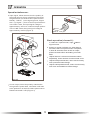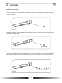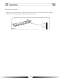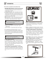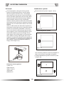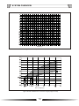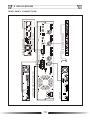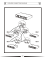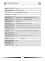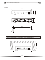
1
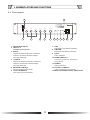
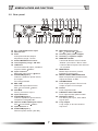
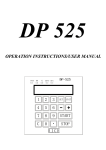
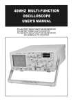
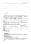
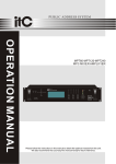
PUBLIC ADDRESS SYSTEM
OPERATION MANUAL
T-10ALP
MIXER LOOP AMPLIFIER
5
1
T-10ALP
MIXER LOOP AMPLIFIER
+6 dB
0 dB
10
OUTPUT CURRENT
POWER
-6 dB
-20 dB
-40 dB
INPUT 2
INPUT 1
4
5
6
4
7
3
8
2
9
1
0
10
5
INPUT 3
6
4
7
3
8
2
9
1
0
10
5
BASS
6
-1
7
3
8
2
9
1
0
10
0
-1
+2
+3
-3
+4
-4
-5
+5
MASTER
TREBLE
+1
-2
0
4
+2
+3
-3
+4
-4
-5
5
6
+1
-2
3
7
1
9
ON
8
2
LOOP
AGC
INTEGRITY
LIMITER FAULT OFF
+5
0
10
Please follow the instructions in this manual to obtain the optimum results from this unit.
We also recommend that you keep this manual handy for future reference.
TABLE OF CONTENTS
1. SAFETY PRECAUTIONS .............................................................................................3
2. FEATURES ........................................................................................................... .... .5
3. NOMENCLATURE AND FUNCTIONS
3 .1 Front Panel .......................................................................................................... 6
3. 2 Rear Panel............................................................................................................7
4. OPERATION INSTRUCTION
4.1 Operation before use............................................................................................. 8
4.2 Basic operation (channel 1)....................................................................................9
4.3 Function operation...............................................................................................10
4.4 Function operation introduction.............................................................................13
4.5 Guidance of excluding errors.................................................................................14
5. SYSTEM OVERVIEW
5 .1 Principle.............................................................................................................15
5.2 Assistive listening device.....................................................................................15
5.3 Quadrature system...............................................................................................15
5.4 Expanded quadrature systems..............................................................................16
5.5 Low-spill system..................................................................................................16
5.6 Induction loops....................................................................................................17
5.7 Magnetic field strength.........................................................................................17
6. APPLICATIONS.........................................................................................................19
7. DEVICES CONNECTION DIAGRAM ..........................................................................20
8. BLOCK DIAGRAM......................................................................................................21
9. SPECIFICATIONS..................................................................................................... 22
10. DIMENSION FIGURE...............................................................................................23
2
1. SAFETY PRECAUTIONS
Be sure to read the instructions in this section carefully before use.
Make sure to observe the instructions in this manual as the conventions of safety symbols and messages
regarded as very important precautions are included.
We also recommend you keep this instruction manual handy for future reference.
Safety Symbol and Message Conventions
Safety symbols and messages described below are used in this manual to prevent bodily injury and property
damage which could result from mishandling. Before operating your product, read this manual first and
understand the safety symbols and messages so you are thoroughly aware of the potential safety
Indicates a potentially hazardous situation which, if mishandled, could
result in death or serious personal injury.
Indicates a potentially hazardous situation which, if mishandled, could
result in moderate or minor personal injury, and/or property damage.
When Installing the Unit
When Installing the Unit
Do not expose the unit to rain or an environment
where it may be splashed by water or other liquids,
as doing so may result in fire or electric shock.
Should the following irregularity be found during
use, immediately switch off the power, disconnect
Use the unit only with the voltage specified on
the unit.Using a voltage higher than that which
is specified may result in fire or electric shock.
attempt to operate the unit in this condition as this
may cause fire or electric shock.
If you detect smoke or a strange smell coming
from the unit.
If water or any metallic object gets into the unit
If the unit falls, or the unit case breaks
If the power supply cord is damaged (exposure
of the core, disconnection, etc.)
If it is malfunctioning (no tone sounds.)
the power supply plug from the AC outlet and contact
y our nearest ITC dealer. Make no further
Do not cut,kink otherwise damage nor modify the
power supply cord. In addition, avoid using the
power cord in close proximity to heaters, and never
place heavy objects - including the unit itself - on
the power cord, as doing so may result in fire or
electric shock.
To prevent a fire or electric shock, never open nor
remove the unit case as there are high voltage
components inside the unit. Refer all servicing
to your nearest ITC dealer.
Be sure to replace the unit's terminal cover after
connection completion. Because high voltage
is applied to the speaker terminals, never touch
these terminals to avoid electric shock.
Do not place cups, bowls, or other containers of
liquid or metallic objects on top of the unit. If they
accidentally spill into the unit, this may cause a
fire or electric shock.
Be sure to ground to the safety ground (earth)
terminal to avoid electric shock. Never ground
to a gas pipe as a catastrophic disaster may result.
Do not insert nor drop metallic objects or flammable
materials in the ventilation slots of the unit's cover,
as this may result in fire or electric shock.
Avoid installing or mounting the unit in unstable
locations, such as on a rickety table or a slanted
surface. Doing so may result in the unit falling
down,causing personal injury and / or property
damage.
3
When Installing the Unit
When Installing the Unit
Never plug in nor remove the power supply plug
with wet hands, as doing so may cause electric
shock.
Do not place heavy objects on the unit as this may
cause it to fall or break which may result in personal
injury and/or property damage. In addition, the object
itself may fall off and cause injury and/or damage.
When unplugging the power supply cord, be sure
to grasp the power supply plug; never pull on the
cord itself. Operating the unit with a damaged
power supply cord may cause a fire or electric
shock.
Make sure that the volume ontrol is set to minimum
position before power is switched on. Loud noise
produced at high volume when power is switched
on can impair hearing.
When moving the unit, be sure to remove its power
supply cord from the wall outlet. Moving the unit
with the power cord connected to the outlet may
cause damage to the power cord, resulting in fire or
electric shock. When removing the power cord, be
sure to hold its plug to pull.
Do not operate the unit for an extended period of
time with the sound distorting. This is an indication
of a malfunction, which in turn can cause heat to
generate and result in a fire.
Do not block the ventilation slots in the unit's cover.
Doing so may cause heat to build up inside the unit
and result in fire.
Contact your ITC dealer as to the
cleaning. If dust is allowed to accumulate in the
unit over a long period of time, a fire or damage
to the unit may result.
Avoid installing the unit in humid or dusty locations,
in locations exposed to the direct sunlight, near the
heaters, or in locations generating sooty smoke or
steam as doing otherwise may result in fire or
electric shock.
If dust accumulates on the power supply plug or in
the wall AC outlet, a fire may result. Clean it periodically. In addition, insert the plug in the wall outlet
securely.
Due to product upgrades, while some of the
features and specification in the user manual
does not match the actual functions, sorry for
any inconvenience and thanks for your kind
understanding!
Switch off the power, and unplug the power supply
plug from the AC outlet for safety purposes when
cleaning or leaving the unit unused for 10 days or
more. Doing otherwise may cause a fire or electric
shock.
An all-pole mains switch with a contact separation of at least 3 mm in each pole shall be incorporated in
the electrical installation of the building.
4
2. FEATURES
1. 3 Mic/Line Inputs.
2. Individual Volumn Control.
3. 240W /10A Output.
4. Build-in Low-pass 5KHz/10KHz.
5. Built-in AGC, limiter metal compensation circuit metal.
6.Built-in signal level, the current level indicator.
7. 2 levels of priorities: Input 1 higher than input 2-3. Fire alarm 100V input higher than input 1-3.
8. Faulty output feature.
9. Auxiliary 0 C phase oupput and 90 C phase output automatically adjusts.
5
3. NOMENCLATURE AND FUNCTIONS
3.1 Front panel
13
12
5
1
+6 dB
0 dB
10
OUTPUT CURRENT
POWER
-6 dB
-20 dB
-40 dB
INPUT 2
INPUT 1
4
5
6
4
7
3
9
1
0
10
INPUT 3
6
4
7
3
8
2
5
9
1
0
10
BASS
6
-1
7
3
8
2
5
9
1
0
10
-1
+2
+3
-3
+4
-4
+5
-5
MASTER
TREBLE
+1
-2
8
2
0
0
4
+2
-2
+3
-3
+4
-4
-5
5
3
7
1
9
2
3
ON
8
2
LOOP
AGC
INTEGRITY
LIMITER FAULT OFF
+5
10
0
1
6
+1
4
1. EARPHONE INPUT
2. INPUT1-3
volumn control knob
3. BASS
Adjust the bass response, clockwise
rotation,Increa se the bass output,
whereas reduced.
4. TREBLE
Adjust the treble response, clockwise
rotation,Increase the treble output,
whereas reduced.
5. MASTER CONTROL
Control all the output level.
6. LOOP INTEGRITY
Full output circuit indicator.
5
6
7
8
9
10
11
7. AGC
Automatic gain status indicator
8. LIMITER
Pressure limit status indicator.
9. FAULT
Fault indicator.
10.POWER SWITCH
Turn on by press up, Turn off by
press down.
11.POWER
Power indicator.
12. OUTPUT CURRENT
Loop output current indicator.
13.BUILT-IN SIGNAL LEVEL INDICATOR
6
NOMENCLATURE AND FUNCTIONS
3.2 Rear panel
37 36
39 38
LOOP
OUT
35 34
33 32 31 30
PRIORITY INPUT
COM
100V
FAULT
0
MASTER IN
VULED
SLAVE OUT
90
0
SUPERVISION
NO
LINE OUT
C
ON
NC
INPUT 1
OFF
MASTER
SLAVE
MATAI LOSS
COMPENSATION
INPUT 2
INPUT 3
2
2
AGC
2
AGC LIMITER
5K
10K
1
3
PHANTOM
1
3
PHANTOM
1
3
PHANTOM
USE ONLY WITHA 250V FUSE
ON
14
15
16 17 18 19
OFF
MIC
LINE
VOX
MIX
20 21 22 23
14. AC ~115V-230V Power input
15. Radiator Fan
16. AGC
AGC potentiometer,Output
adjustment range: 1V-28V
17. AGC/LIMITER Gain Control
18. Low frequency range : 5K-10K
19. LINE OUT
Pre-line balanced output, standard
output of about 500mV
20. Input channel 1
Balanced input signal is 385mV
21. PHANTOM( Input 1)
Channel 1 phantom power switch,
the output
DC voltage DC48V
22. MIC LINE
MIC/LINE Input switch button
MIC: 2.5mV/LINE: 385mV
23. VOX MIX
Priority control for input 1
24. Input Channel 2
25. PHANTOM( Input 2)
Channel 2 phantom power switch,
Output DC voltage DC48V
26. Channel 2 MIC/LINE input switch
MIC: 2.5mV/LINE: 385mV
27. Input Channel 3
28. PHANTOM( Input 1)
Phantom power switch (48V DC)
ON
24
OFF
MIC
LINE
25 26 27
ON
OFF
MIC
LINE
28 29
29. MIC/LINE Input switch
MIC: 2.5mV/LINE: 385mV
30. Auxiliary 90 C phase oupput
31. Auxiliary 0 C phase output
32. MASTER /SLAVE
It works as 'Master' when it shows
" Master " ;it works as 'Slave' when
it shows " Slave " Inputs from channel
1-3 is invalid.
33. MASTER IN
Master input terminal (775mV
unbalance signal input)
34. MATAI LOSS COMPENSATION
Metal compensation potentiometer,
adjust the effect :0-8dB.
35. SUPERVISION
Fault output optional: Short circuit
output or Open circuit output.
36. FAULT
Fault output terminal.
37. PRIORITY INPUT VOLUME
Prior input terminal poteniometer.
38. PRIORITY INPUT
Fire alarm prior input, 100V alarm
signal input.
39. Loop output
Loop output, to be connected to
loop load.
7
4. OPERATION
Operation before use:
Please check whether the power voltage is
consistent with the local network before turn on
the power, then set the control elements as the
below table (Figure 1):
!
Note:
After setting the following switchs and
control parts, then input signal source, and
then connected to the circuit output load.
figure 1
Defult Configuration:
FUNCTION
NUMBER
SET
Power
10
Turn Off
Master Volume
5
" " scale
Trebel
4
Middle
Bass
3
Input channel 1-3
2
" "scale
Master/Slave Switch:
32
Master
Automaticly Gain Control
17
Limiter
Low-frequency Control:
18
Music 10K, Mic 5K Prior
Metal Compensator
34
Turn right to the maximum
Phantom Power Switch
21 25 28
Turn Off
Line Input Selector
22 26 29
Line
8
Middle
OPERATION
Operation before use:
Input signal, follow the match on the polarity of
the signal source wiring, otherwise it will cause
the generation of machine failure phenomenon.
Namely: "INPUT" 1) foot signal ground; Signal
the"+";2) Signal "-" pole. Channel input selection:
in the "MIC" state, the input signal voltage is
approximately: 5mV or so. Channel output options:
in the "LINE" state, the input signal voltage is
approximately 775mV (Figure 2).
figure 3
Basic operation (channel 1):
In channel 1 input terminal, input
signal source.
385mV
Switch on, power indicator on, after about 5
seconds, there is output function in amplifier,
if after 30 seconds, there is still no output,
please recheck switch and setting of control
knob.
Adjust channel 1 volume and master volume
separately, users can hear loud and clear voice.
Adjust bass potentiometer, users can obviously
feel a powerful bass change.
Adjust treble potentiometer, users can obviously
feel clear and melodious treble change.
figure 2
Circuit output, follow the polarity matches the
wiring and the power load, otherwise it will lead
to the production of machine failure phenomenon.
Rated load: 240W / 3 EU (Figure 3)
9
OPERATION
Function operation
Panel indicators introduction as below:
" LOOP " indicator---Completed loop indicators, the indicators are green. when there is output
prompt in left level indicators, but the right "LOOP" indicator is off,it means opened status.
(Refer to figure 4)
L00P
INTEGRITY
figure 4
" AGC " indicator---In automatic gain status, the indicators are green. when automatic gain effect
in max status, indicators will be dark, but it will not affect "AGC" function. (Refer to figure 5)
AGC
figure 5
" LIMITER " indicator---Pressure limit indicator, the indicators are orange, it means output signal
in pressure limit status. (refer to figure 6)
LIMITER
figure 6
10
OPERATION
Function operation
" FAULT " indicator---Faulty indicator, the indicators are red, it means thereis faulty in the device.
(refer to figure 7)
FAU LT
figure 7
" POWER " indicator--- Power indicator, the indicators are blue, it means the device is in working
status. (refer to figure 8)
POWER
figure 8
" OUTPUT CURRENT" indicator---Output power indicator, it need to connect with overload, the
indicators will show the amplifier output working current, range from 1-10A. (refer to figure 9)
1
5
OUTPUT CURRENT
figure 9
11
10
OPERATION
Function operation
"Built in signal level"indicator---power indicator, No.+6 indicator is red, it means device output
signal source exceeds standard status. (Refer to figure 10)
+6 dB
0 dB
-6 dB
-20 dB
-40 dB
figure 10
12
OPERATION
Function operation introduction:
Automatic gain function: When automatic gain
is dialed on AGC position, choose automatic gain,
it can adjust Gain Potentiometer and choose
output range: 1V-28V.
Low pass function: When low pass frequency
is dialed on 10K position, signal frequency start
toattenuate above 10K, range about 3dB; dialed
on 5K position, signal frequency start toattenuate
above 5K, range about 3dB.
Mute function : There is 2 level priority function,
the first priority is 100V fire alarm signal input,
then input 1 is priority than input 2, input 3.
!
NO
figure 11
Note:
When the device is used as slave, all the
Metal compensation function: When signal
source is in 3KHZ frequency, adjust "Metal
compensation" potentiometer, it will show
treble changes.
priority function is invalid.
When Priority Select:
1)When in vox, input1 is priority than input 2
and input 3.
2)In mix, input 1, input 2 and input 3 mix input.
Fire alarm first priority function: When in
priority input terminal input 100V fire alarm sig nal
source, device is in first priority level, users can
adjust Priority volume potentiometer,choose the
size of input signal.
!
NC
C
Master and Slave function:1)When "Master
& Slave selection" is in "MASTER", the device
is inmaster working status, it can operate
normally, 2)When "Master & Slave selection"
is in "SALVE", the device is in slave working
status. 3) When in slave status, these terminals
"PRIORITYINPUT","NPUT1", "NPUT2" , "INPUT3"
are invalid, all are shielded. It can only input
about 775mV signal in Master input.
Note:
When the device is in slave status,
the function is invalid (means no output).
Faulty output function
1)" SUPERVISION " is "ON", "FAULT" terminal, in
device normal working status, "C" foot and "NC"
foot is in short circuit status, when there is faulty
in device, it is in opened status, it means "C "foot
and "NC "foot is opened.
2) " SUPERVISION " is off, in device normal
working status, "FAULT DUANK" , "C" foot and
"NC" foot is in opened status, when there is faulty
in device, it is in short circuit status, it means "C"
foot and "NC" foot is short circuit. (refer to figure
11)
AUX output: There is Aux 90 phase position
about 1V signal and Aux 0 phase position
about 1V signal output in Aux output.
Earphone function: Front panel earphone
jack parallel output balanced signal 1.2V.
Pre output function: " LINE OUT" output
balanced signal about 500mV(refer to figure
12).
figure 12
13
OPERATION
GUIDANCE OF EXCLUDING ERRORS
CAUSE
PHENOMENA
All the wires are connected well but no
voice output
1
2
3
4
No power or wrong plug connection
Fuse is burned
Volume is town off
No input signal
Power on but alarming signal
1 Overloading or short circuit
2 Voltage is not stable, too high or low
No voice output in normal condition
1 Machine is in protection condition in case of high
temperature
2 Wrong wire connection
14
5.SYSTEM OVERVIEW
Principle
Quadrature system
The loop amplifier changes incoming audio
signalin an alternating electric current that is
sent through the induction loop. The strength
and frequency of the electric current varies with
the tone and the amplitude of the incoming audio
signal and generates and alternating magnetic
field inside the induction loop. People with
assistive listening devices who are located inside
the induction loop,can put their assistive listening
devices in the T or MT mode to listen to the audio
signals.
In the T or MT mode, the internal microphone of
the assistive listening devices is switched off and
a little coil is activated (T standsfor "Tele-coil").
The coil receives the alternating magnetic field
and changes it into an alternating voltage, which
the assistive listening devices change into an
audio signal. This audio signal is not entirely the
same asthe incoming audio signal of the loop
amplifier, because the assistive listening devices
also compensate for individual hearing disabilities
(for example, signal strength and frequency
range, refer to figure 13).
Brief introduction (refer to figure 14/15)
figure 14
Simple single loop system
figure 15
Simple multiple loop system
One of the key features of the loop amplifier is
that it can be used in quadrature systems.
A simple Quadrature system consist of (refer
to figure 16)
figure 13
Assistive listening device
1)Tele-coil
2)Microphone
3)Gain control
4)Amplifier
5)Earphone
figure 16
15
SYSTEM OVERVIEW
A master loop amplifier (M) with one induction
loop.
A slave loop amplifier (S) with one induction loop.
(refer to figure 16)
To cover larger areas, create a basic system with
multiple induction loops (refer to figure 17).
figure 18
Low-spill system:
figure 17
A master loop amplifier(M) with multiple induction
loops. A slave loop amplifier (S) with multiple
induction loops.
!
Note:
All master and slave induction loops
must have the same size.
Expanded quadrature systems:
To cover very large areas, create an expanded
quadranture system (refer to figure 18 for an
example). Such a system consist of: a master
loop amplifier (M) with one or more induction
loops. All master induction loops must have the
same size. An odd number of slave amplifiers
(S1, S2, S3, etc.) with one or more induction
loops. All slave induction loop must have the
same size.
16
A special type of quadrature systems is the
low-spill system (refer to figure 19). a low-spill
system makes sure that the magnetic field
strength drops even more rapid to zero beyond
the borders of the covered area. Such a system
consist of:a master loop amplifier(M) with one
or more induction loops. All master induction
loops must have the same size. An odd number
of slave amplifier (S1 in this example) with one
or more induction loops. All slave induction
loops must have the same size. Two slave
amplifier(S2 and S3 in this example) with one
induction loop. The width of the induction loops
must be between 50 and 60% of the width of the
master induction loop.
SYSTEM OVERVIEW
When the distance between the floor and the
induction loop is too small (less than 8% of the
width) or too large (more than 20% of the width),
refer to figure 20. The figure 21 shows the extra
power that the loop amplifier needs to make the
correct magnetic field. The numbers next to the
curves show the distance from the floor to the
induction loop in % of the width (W) of the room.
figure 19
Induction loops:
Introduction When you make an induction loop,
you must take a number of parameters into
consideration. However, sometimes there are
special situations, which make the design and
panning of the induction loop even more important. a number of potential problems and solutions
will be discussed later.
Position For the best audio quality and the
smallest variation in the magnetic field strength,
the distance between the induction loop and the
listening planemust be between 12 and 15% of
the width of the room(refer to figure 20).
Wire diameter
For the best audio quality, the DC(direct current) resistance of the induction loop must be
between1 and 3 . The DC resistance depends
on the wire diameter and the wire length.
Do as follows:
1)Calculate the wire length. The wire length
depends on the size of the induction loop.
2)Use figure 22 to get the allowed wire diameter. for example, in a rectangular room with a
width (W) of 10m and a length (L) of 30m, the
wire length is 80m. According to figure 22, the
wire diameter must be between 0.77 and 1.34
mm. Thus, you can use AWG20 wire or a wire
with a standard diameter of 1.00mm.
Magnetic field strength :
For the best audio quality, the vertical component of the magnetic field must be 100 mA/m
3dB at 1.2m above the floor inthe area that
is surrounded by an induction loop. The
strength of the magnetic field depends on the
electric current through theinduction loop.
Peaks in the strength of themagnetic filed must
be less than 40 mA/m at 1.2m above the floor
in the area that is surrounded by the induction
loop.
figure 20
For example, in a room with a width (W) of 10M,
the induction loop should be installed 0 to 0.4 m
below or 2.4 to 2.8 m above the floor for the best
audio quality and the smallest variation in the
magnetic field strength. Typically, you will install
the induction loop in the floor in the ceiling of a
room.
17
SYSTEM OVERVIEW
Width(%)
figure 21 Extra power vs.the width of the room
Wire length(m)
figure 22 Wire diameter vs. the wire length (copper wires)
18
70V 100V
+
EMC INPUT
MUTE
MIC 2
MIC 3
MIC3
MIC2
LINE INPUT
AUX1
INPUT
AUX2
INPUT
MIX
OUT
19
USE ONLY WITHA 250VFUSE
LIFT
GND
AMPLIFIER
USE ONLY WITHA 250V FUSE
OUTPUTS
COM COM COM 4-16
70V 100V
2
3
1
AGC LIMITER
5K
10K
100V
LINE OUT
COM
LOOP
OUT
http://www.lineartechnologie.fr
AGC
CONDUCTING WIRE IN THE SAME WAY
USE ONLY WITHA 250V FUSE
OUTPUT
COM COM COM 4-16
0
2
3
1
INPUT 1
ON
MIC
C
10K
LINE OUT
100V
0
2
3
1
INPUT 1
ON
OFF
PHANTOM
PRIORITY INPUT
MIC
NO
LINE
NC
VOX
MIX
ON
OFF
2
3
1
INPUT 2
MATAI LOSS
COMPENSATION
SUPERVISION
ON
OFF
PHANTOM
MIC
LINE
LINE
NC
GND
PRIORITY
CHIME
LED PWR
7
6
1
3 1
524
2
3
MIC INPUT
P.T.T 1
4
5
6
7
MIC 4
GAIN 4
MIC 3
2
3
1
GAIN 3
MIC 2
GAIN 2
MIC 1
VOX
+48V PHANTOM
2
ON
ON
1 2 3 4
ON
ON
ON
OFF OFF OFF OFF
MIC1 MIC2 MIC3 MIC4
GAIN 1
2
EMC
3
3
1
INPUT 2
MATAI LOSS
COMPENSATION
ON
OFF
PHANTOM
1
AUX 3
0
MIC
90
LINE
INPUT
AUX 2
ON
AUX 1
OFF
REC
2
1
90
OFF
LINE
ON
1
3
2
MIC
+
DC 24V
PHANTOM
OUTPUT
MIC
3
0
SLAVE OUT
INPUT 3
SLAVE
VULED
MASTER
MASTER IN
PHANTOM
SLAVE OUT
OFF
INPUT 3
SLAVE
MIX
ON
SUPERVISION
VULED
MASTER
MASTER IN
C
FAULT
FAULT DETECTION HOST
FAULT
NO
5K
http://www.lineartechnologie.fr
AGC LIMITER
COM
PRE-AMPLIFIER/MICROPHONE
OFF
PHANTOM
PRIORITY INPUT
USE ONLY WITHA 250V FUSE
AGC
OUT
LOOP
MIXER LOOP AMPLIFIER
LINE
6. APPLICATIONS
REAR PANEL CONNECTIONS
7. DEVICES CONNECTION DIAGRAM
20
8. BLOCK DIAGRAM
21
9. SPECIFICATIONS
Model
T-10ALP
Frequency response
50Hz-10KHz(+1/-3dB)
Distortion
<1% (Rated output power) 1KHz
Bass control
10dB,100Hz
Treble control
10dB,10kHz
Mic/line input
3 roads XLR connectors, balanced mic/line level (switchable)
Sensitivity
5mV/0.775V(mic/line) impedance 1K ohms
Phantom power
+48V switchable
VOX function
input 1 road (switchable) mute input 2-3 roads
100V connectors priority
input balance input, impedance >10K ohms, priority input 1-3 roads
Mina input
1 road connector 6.3 phone jack, rated level 1V impedance 10K ohms
Line output
XLR balanced connectors, rated level 1V impedance 200 ohms
Aux output
connector 6.3 phone jack 0 or 90, rated level 1V impedance 200 ohms
SNR
63dB
Loop output
rated current 6A
Maximum output current is 10A
Current
AC 230V/115V 10
Max power consumption
500VA
Dimension(mm)
484X390X88
Weight
10.3kg
,50/60Hz
22
10. DIMENSION FIGURE
Unit:mm
484
5
1
+6 dB
0 dB
10
OUTPUT CURRENT
POWER
88
-40 dB
INPUT 2
INPUT 1
4
5
6
4
7
3
9
1
0
10
5
INPUT 3
6
BASS
-1
5
4
6
+1
ON
8
2
+3
+4
-4
7
3
+2
-3
+5
-5
0
-2
+3
+4
-4
MASTER
TREBLE
+2
-3
10
0
+1
-2
8
9
1
10
0
-1
7
2
9
0
6
3
8
2
1
5
4
7
3
8
2
LOOP
AGC
INTEGRITY
9
1
94
-6 dB
-20 dB
LIMITER FAULT OFF
+5
-5
10
0
436
LOOP
OUT
PRIORITY INPUT
100V
COM
FAULT
0
MASTER IN
VULED
SLAVE OUT
90
0
C
ON
NC
INPUT 1
LINE OUT
OFF
MASTER
SLAVE
84
SUPERVISION
NO
MATAI LOSS
COMPENSATION
INPUT 2
INPUT 3
AGC
2
5K
AGC LIMITER
1
10K
2
1
PHANTOM
3
2
PHANTOM
3
1
3
PHANTOM
USE ONLY WITHA 250V FUSE
ON
OFF
MIC
LINE
VOX
MIX
ON
OFF
MIC
LINE
ON
OFF
MIC
LINE
321
84
25
6
The loop amplifier should keep 10cm distance with the objects which block the
air circulation, in order to avoid internal device temperature rise.
10
OUTPUT CURRENT
Over 100
5
1
+6 dB
0 dB
POWER
-6 dB
-20 dB
-40 dB
INPUT 2
INPUT 1
4
5
6
4
7
3
9
1
0
10
5
6
4
7
3
8
2
INPUT 3
9
1
0
10
5
6
-1
7
3
8
2
BASS
9
1
0
10
0
+1
-1
+2
-2
8
2
+3
-3
+4
-4
-5
+5
MASTER
TREBLE
0
4
+3
ON
7
8
2
9
1
LOOP
AGC
INTEGRITY
LIMITER FAULT OFF
+5
0
Over 100
6
3
+2
+4
-4
-5
5
+1
-2
-3
10
Over 100
23
PUBLIC ADDRESS SYSTEM
PUBLIC ADDRESS SYSTEM
VersionV0.3