1
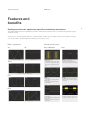
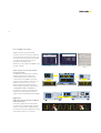
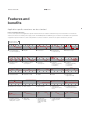
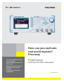
How can you replicate
real world signals?
Precisely
tç)[UP.)[7QQ
PSDIBOOFMT
t*OUVJUJWFPQFSBUJPOXJUIBw
LCD screen
FG400 Series
Arbitrary/Function Generator
t4ZODISPOJ[FVQUPVOJUTUP
QSPWJEFVQUPPVUQVU
DIBOOFMT
t"WBSJFUZPGTXFFQTBOE
modulations
Bulletin FG400-01EN
Features and benefits
FG400 Series
Features and
CFOFýUT
&BTJMZHFOFSBUFCBTJDBQQMJDBUJPOTQFDJýDBOEBSCJUSBSZXBWFGPSNT
The FG400 Arbitrary/Function Generator provides a wide variety of waveforms as standard and generates signals
simply and easily.
There are one channel (FG410) and two channel (FG420) models. As the output channels are isolated, an FG400
can also be used in the development of floating circuits. (up to 42 V)
Basic waveforms
4JOF
Advanced functions
4XFFQ.PEVMBUJPO
DC
0.01 μHz to 30 MHz
±10 V/open
4RVBSF
Burst
Frequency sweep
Setting items
start/stop frequency, time, mode
(continuous, single, gated single),
function (one-way/shuttle, linear/
log)
"VUP
Oscillation and stop are
automatically repeated with the
respectively specified wave number.
18.
Setting items
carrier duty, peak duty deviation
Output duty
the range of carrier duty ±peak
duty deviation
Trigger
Oscillation with the specified wave
number is done each time a trigger
is received.
".
Setting items
carrier amplitude, modulation depth
Output amp.
the range of amp./2 × (1 ±mod.
Depth/100)
Gate
Oscillation is done in integer cycles
or half cycles while the gate is on.
0.01 μHz to 15 MHz, variable duty
Pulse
0.01 μHz to 15 MHz, variable leading/trailing edge time
Ramp
0.01 μHz to 5 MHz, variable symmetry
2
3
For trouble shooting
Arbitrary waveforms (16 bits amplitude
resolution) of up to 512 K words per waveform
can be generated. 128 waveforms with a total
size of 4 M words can be saved to the internal
non-volatile memory. Waveforms can be
selected from the displayed list.
Waveforms can be created in the FG400 or with
the editor software.
The list of arbitrary waveforms
Editing screen in the FG400
Editing screen of the editor
software
"DRVJSFTJHOBMOPJTFJOUIFýFMEBOEUIFO
SFDSFBUFJUJOUIFMBC
The FG400 can generate signals as arbitrary
waveforms that have been acquired by
measuring instruments. Trouble shooting
is made easier as the FG400 can generate
waveforms that are difficult to reproduce. For
example noise that only occurs on site.
With the XviewerLITE software (freeware),
waveform (binary data) that is acquired using
a YOKOGAWA DL850E or DLM4000 can
be analyzed on the PC to find the abnormal
waveform. This abnormal part can then be
clipped, saved and generated using the FG400.
<"QQMJDBUJPO>
$MJQQJOHUIFBCOPSNBMTJHOBMUIFOBEEJOHJU
UPUIFOPSNBMTJHOBM
Connect the clipped abnormal signal output
of channel 2 to the additional input terminal of
channel 1, and then press the Manual trigger
key. The abnormal signal is added to the normal
pulse waveform that is set on channel 1.
Generation
Acquisition
addition
Features and benefits
FG400 Series
Features and
CFOFýUT
4
Application-specific waveforms are also standard
1BSBNFUFS7BSJBCMF8BWFGPSNT
In some cases engineers need application-specific waveforms like those needed to evaluate the response characteristics of mechanical/
electrical circuits and to emulate power supply circuits. The FG400 provides 25 different types of waveform as standard. As the parameters
of application-specific waveforms can be changed like those of basic waveforms, waveforms are quicker and easier to generate.
Waveform name
t7BSJBCMF1BSBNFUFST
1
6OCBMBODFETJOF
2
t'JSTUIBMGBNQMJUVEF
t4FDPOEIBMGBNQMJUVEF
6
.VMUJDZDMFTJOF
(BVTTJBOQVMTF
4JOY
Y
$'DPOUSPMMFETJOF
4
t$SFTUGBDUPS
$POEVDUJPOBOHMF
DPOUSPMMFETJOF
5
7
0OQIBTFDPOUSPMMFETJOF
8
t$PNQMFUFPOQIBTF
t0OTMPQFUJNF
12
-PSFOU[QVMTF
17
&YQPOFOUJBMSJTF
0GGQIBTFDPOUSPMMFETJOF
9
t0GGQIBTF
t0GGTMPQFUJNF
13
t)BMGWBMVFPGXJEUI
t/VNCFSPG[FSPDSPTTJOHT
t/VNCFSPGTUFQT
)BWFSTJOF
18
&YQPOFOUJBMGBMM
10
t0OQIBTF
t/VNCFSPGDIBUUFSJOH
t0OTUBUFUJNF
t0GGTUBUFUJNF
14
t8JEUI
t5JNFDPOTUBOU
$IBUUFSJOHPOTJOF
)BMGTJOFQVMTF
15
t8JEUI
19
t5JNFDPOTUBOU
4FDPOEPSEFS-1'
TUFQSFTQPOTF
0TDJMMBUJPOTVSHF
t0TDJMMBUJPOGSFRVFODZ
t%BNQJOHUJNFDPOTUBOU
t5SBJMJOHUJNFDPOTUBOU
22
1VMTFTVSHF
t3JTJOHUJNF
t%VSBUJPOUJNF
23
5SBQF[PJEXJUIPGGTFU
t-FBEJOHEFMBZ
t3JTJOHTMPQFXJEUI
t6QQFSCBTFXJEUI
t'BMMJOHTMPQFXJEUI
t0GGTFU
24
)BMGTJOFFEHFQVMTF
t-FBEJOHFEHFUJNF
t5SBJMJOHFEHFUJNF
t%VUZ
$IBUUFSJOHPGGTJOF
t0GGQIBTF
t/VNCFSPGDIBUUFSJOH
t0OTUBUFUJNF
t0GGTUBUFUJNF
5SBQF[PJEQVMTF
t4MPQFXJEUI
t6QQFSCBTFXJEUI
20
%BNQFEPTDJMMBUJPO
t0TDJMMBUJPOGSFRVFODZ
t%BNQJOHUJNFDPOTUBOU
t-1'OBUVSBMGSFRVFODZ
t-1'2
21
4UBJSDBTF4JOF
t$POEVDUJPOBOHMF
t4UBOEBSEEFWJBUJPO
16
3
t$MJQSBUF
t/VNCFSPGDZDMFT
t4UBSUQIBTF
11
$MJQQFETJOF
25
#PUUPNSFGFSFODFESBNQ
t4ZNNFUSZ
5
Manually program waveform patterns
4FRVFODFGVODUJPO
Sequences of different waveform patterns can be generated
by programming the parameters. Complex sequences can
be easily created using the “Sequence Edit Software”.
Available parameters include:
waveform, frequency, phase, amplitude, DC offset,
square wave duty, step time, hold operation,
jump destination, number of jumps, step stop phase,
branch operation, step termination control,
step sync code output
Step
Waveform
Frequency
Offset
Sweep
1
Sine
1 kHz
0V
—
2
Sine
1 kHz
1.5 V
—
3
Sine
1 kHz
3V
—
4
DC
—
0V
ON
When 2 channels are linked (FG420 only)
In the FG420 the two output channels can be linked.
In this mode, both output signals vary when either channel
is adjusted.
t Independent: Independent setting
t 2- phase: Holds the same frequency
GSFRVFODZ
amplitude
t Constant frequency difference:
Holds the frequency difference as a constant value
t Constant frequency ratio:
Holds the frequency ratio as a constant value
%$PGGTFU
Example of the differential output
t Differential output:
Same frequency, amplitude, and DC offset. Reverse
phase waveform
When you need more than 2 channels
By synchronizing multiple FG410 and FG420s, a generator
of up to 12 phases (using six FG420s) can be created.
The phase of each channel is synchronized to the master
unit and can be individually adjusted.
Greater accuracy and stability
The FG400 has an external input terminal to increase
frequency accuracy and stability by using a frequency
reference with better accuracy than the built-in reference (for
example, a rubidium frequency standard).
Master unit
10 MHz
REF IN
REF
OUT
Slave unit
10 MHz
REF IN
Use of external
T divider
reference possible
Slave unit
REF
OUT
10 MHz
REF IN
Slave unit
REF
OUT
10 MHz
REF IN
50 Ω
termination
resistor
T divider
Connection method 1 (up to 6 units)
Master unit
10 MHz
REF IN
REF
OUT
Slave unit
10 MHz
REF IN
REF
OUT
REF
OUT
Slave unit
10 MHz
REF IN
Use of external
reference possible
Connection method 2 (up to 4 units)
REF
OUT
Input/output terminal and Specification of FG400
FG400 Series
*OQVUPVUQVUUFSNJOBM
'(DI
6
7
8
9
7
8
9
4
'(DI
4
$)*0UFSNJOBMT
$PNNPO*0UFSNJOBMT
$)*0UFSNJOBMT
Waveform output
External 10 MHz frequency reference input
Waveform output
Sync/sub-output
Frequency reference output
Sync/sub-output
external modulation/addition input
7
Multi-I/O connector
external modulation/addition input
4
external trigger input
8
GPIB connector
external trigger input
9
USB connector
Specification of FG400
0VUQVUBOE0TDJMMBUJPO.PEFT
Number of channels
FG410: 1 channel
Sync/sub output
Output voltage Sync signals:
TTL level
Internal modulation signal: −3 V to +3 V/open
Sweep X drive:
0 V to +3 V/open
FG420: 2 channels
Output waveforms
Sine, square, pulse, ramp, parameter-variable waveform,
noise (Gaussian distribution), DC, arbitrary waveform
Oscillation modes
Continuous, modulation, sweep, burst, sequence
4JOFXBWF
Amplitude frequency
characteristics*1
Frequency
Oscillation mode
Continuous, modulation,
Sweep
(Continuous, Single-Shot)
Sine
0.01 μHz to 30 MHz
Sweep
(Gated Single-Shot),
Burst
Sequence
0.01 μHz to10 MHz
0.01 μHz to10 MHz
0.01 μHz to10 MHz
Square
0.01 μHz to 15 MHz
0.01 μHz to10 MHz
Pulse
0.01 μHz to 15 MHz
0.01 μHz to10 MHz
0.01 μHz to 5 MHz
0.01 μHz to 5 MHz*2
Parameter-variable
waveform
0.01 μHz to 5 MHz
0.01 μHz to 5 MHz*2
Frequency setting invalid
Arbitrary
0.01 μHz to 5 MHz
Frequency setting
resolution
0.01 μHz
Frequency accuracy*1
±(3 ppm of setting + 2 pHz), Aging rate*1 ±1 ppm/year
Phase setting range
−1800.000° to +1800.000°
DC offset
Output impedance
Harmonic spurious
Non-harmonic
spurious*1
Fixed to 26 MHz equivalent bandwidth
DC
0VUQVU$IBSBDUFSJTUJDT
Amplitude
10 Hz to 20 kHz:
*1
not usable
Ramp
Noise
Total harmonic
distortion*1
Setting range
0 Vp-p to 20 Vp-p/open, 0 Vp-p to 10 Vp-p/50 Ω
AC+DC ≤ ±10 V/open
Setting
resolution
999.9 mVp-p or lower 4 digits or 0.1 mVp-p
1 Vp-p or higher 5 digits or 1 mVp-p
Accuracy*1 *4
±(1% of amplitude setting [Vp-p] + 2 mVp-p)/open
Setting units
Vp-p, Vpk, Vrms, dBV, dBm
Resolution
Approx. 14 bits (36 mVp-p/open or higher)
100 kHz or lower: ±0.1 dB
100 kHz to 5 MHz: ±0.15 dB
5 MHz to 20 MHz: ±0.3 dB
20 MHz to 30 MHz: ±0.5 dB (±0.8 dB at 2.8 Vp-p/50 Ω or higher)
(50 mVp-p to 10 Vp-p/50 Ω, reference frequency 1 kHz)
4RVBSFXBWF
Duty
Normal
range
Extended
range
0.5 Vp-p to 2 Vp-p/50 Ω
2 Vp-p to 10 Vp-p/50 Ω
1 MHz or lower
−60 dBc or lower
−60 dBc or lower
1 MHz to 10 MHz
−50 dBc or lower
−43 dBc or lower
10 MHz to 30 MHz
−40 dBc or lower
−30 dBc or lower
1 MHz or lower
−60 dBc or lower
1 MHz to 10 MHz −50 dBc or lower
10 MHz to 30 MHz −45 dBc or lower
(0.5 Vp-p to 10 Vp-p/50 Ω)
0.0100% to 99.9900%
Upper limit (%): 100 − frequency (Hz) / 300,000
Lower limit (%): frequency (Hz) / 300,000
Jitter:
300 ps rms or less typ.
0.0000% to 100.0000%
Jitter:
2.5 ns rms or less typ.
Rising/falling time*1
17 ns or less
Overshoot
5% or less typ.
1VMTFXBWF
Pulse width
0.2% or less (0.5 Vp-p to 10 Vp-p/50 Ω)
Duty setting range:
Time setting range:
Leading edge time,
trailing edge time
Setting range
0.0170% to 99.9830%
25.50 ns to 99.9830 Ms
15.0 ns to 58.8 Ms (3 digits or 0.1 ns resolution)
Leading/trailing edge time independently settable
Minimum setting value Largest of either 0.01% of period or 15 ns
Setting range
±10 V/open, ±5 V/50 Ω
Overshoot
5% or less typ.
Resolution
±499.9 mV or lower 4 digits or 0.1 mV
±0.5 V or higher 5 digits or 1 mV
Jitter
500 ps rms or less typ. (10 kHz or higher) 2.5 ns rms or less typ. (under 10 kHz)
Accuracy*1
±( | 1% of DC offset setting [V] | + 5 mV + 0.5% of amplitude setting
[Vp-p])/open (Sine, 10 MHz or lower, 20ºC to 30 ºC)
50 Ω, unbalanced
3BNQXBWF
Symmetry setting range 0.00% to 100.00%
1BSBNFUFSWBSJBCMFXBWFGPSN
Waveform group
Waveform name
Unbalanced sine, Clipped sine, CF controlled sine, Conduction angle controlled sine,
Staircase sine, Multi-cycle sine
Transient sine group
On-phase controlled sine, Off-phase controlled sine, Chatteringon sine,
Chatteringoff sine
Equivalent setting,
same operation
Set two channels at the same time.
Pulse group
Gaussian pulse, Lorentz pulse, Haversine, Half-sine pulse, Trapezoid pulse, Sin(x)/x
Frequency difference
setting range
0.00 μHz to less than 30 MHz (0.01 μHz resolution)
CH2 frequency − CH1 frequency
Transient response
group
Exponential rise, Exponential fall, Second order LPF step response,
Damped oscillation
Surge group
Oscillation surge, Pulse surge
Frequency ratio N:M
setting range
1 to 9,999,999 (for each of N and M)
N:M = CH2 frequency:CH1 frequency
Other waveform group
Trapezoid with offset, Half-sine edge pulse, Bottom referenced ramp
Phase synchronization
Automatically executed during channel mode switching
"SCJUSBSZXBWFGPSN
Waveform length
7
DIBOOFMHBOHFEPQFSBUJPO'(POMZ
Channel modes
Independent, 2-phase (holds same frequency), Constant frequency difference,
Constant frequency ratio, Differential output (Same frequency, amplitude, and DC
offset. Reverse phase waveform.)
Steady sine group
4 K to 512 K words (2n, n = 12 to 19) or 2 to 10,000 control points
(linear interpolation between control points)
Total waveform saving
capacity
Up to 128 waveforms or 4 M words (combined total for channels 1 and 2) saved to
non-volatile memory
Amplitude resolution
16 bits
Sampling rate
120 MS/s
.PEVMBUJPO
Type
FM
Carrier waveform:
Peak deviation:
FSK
Carrier waveform:
Hop frequency:
PM
Carrier waveform:
Peak deviation:
PSK
Standard waveform other than noise, pulse wave and DC, and
arbitrary waveform
0.00 μHz to less than 15 MHz
Standard waveform other than noise, pulse wave and DC, and
arbitrary waveform
Within settable carrier waveform frequency range
Standard waveform other than noise and DC, and arbitrary
waveform
0.000° to 180.000°
Deviation:
Carrier waveform:
Modulation depth:
Standard waveform other than DC, and arbitrary waveform
0.0% to 100.0%
DC offset
Carrier waveform:
Peak deviation:
Standard waveform and arbitrary waveform
0 V to 10 V/open
PWM
Carrier waveform:
Peak deviation
Square wave:
Square wave, pulse wave
Pulse wave:
Normal variable duty range 0.0000% to 49.9900%
Extended variable duty range 0.0000% to 50.0000%
0.0000% to 49.9000%
Internal modulation
waveform
Other than FSK, PSK: Sine wave, square wave (50% duty),
triangular wave (50% symmetry), rising ramp wave,
falling ramp wave, noise, arbitrary wave
FSK, PSK:
Square wave (50% duty)
Internal modulation
frequency
Other than FSK, PSK: 0.1 mHz to 100 kHz (5 digits or 0.1 mHz)
FSK. PSK:
0.1 mHz to 1 MHz (5 digits or 0.1 mHz)
4XFFQ
Sweep types
Sweep functions
Frequency, phase, amplitude, DC offset, duty
One-way (ramp waveform shape), shuttle (triangular waveform shape) (selectable)
Linear, log (frequency sweep only) (selectable)
Sweep range setting
Start value and stop value specification or Center value and span value specification
Sweep time setting
range
0.1 ms to 10,000 s (4 digits or 0.1 ms)
Sweep mode
Continuous, single-shot, gated single-shot (selectable)
During gated single-shot, oscillation occurs only during sweep execution
Trigger source
Internal, external (selectable)
Internal trigger oscillator Period setting range: 100.0 μs to 10,000 s (5 digits or 0.1 μs)
Stop level setting
Sweep I/O
Burst
Burst mode
Specification of signal level while oscillation is stopped during gated single-shot sweep
Setting range: −100.00% to +100.00% of amplitude full scale or off
Sweep sync/marker output, Sweep X drive output, Sweep external control input,
Sweep external trigger input
Auto burst, Trigger burst, Gate,
Triggered gate (Gate oscillation switched on/off by gate upon trigger)
for synchronizing multiple FG410, FG420 units.
External addition input
Function to add the external signal to the waveform output signal.
1 cycle, 0.5 cycles (selectable)
Phase setting range
−1800.000° to +1800.000°
Stop level
Specification of signal level when oscillation is stopped.
Setting range:
−100.00% to +100.00% of amplitude full scale or off
When the stop level is set to off, stop occurs at the set oscillation start/stop
phase.
Trigger source
Internal, external (selectable). Manual trigger possible
×2/×10/off selectable
The maximum output voltage range is fixed to 4 Vp-p (×2)
or 20 Vp-p (×10).
Voltage/waveform
−1 V to +1 V, DC to 10 MHz (−3 dB)
Input impedance
10 kΩ, unbalanced
Used for sweep and sequence control.
Synchronization of
multiple units
Sync operation is possible. Up to 6 units can be connected with BNC cables in the
form of master/slave connections, using the frequency reference output and external
10 MHz frequency reference input.
User-Defined Unit
Sets and displays the value in any unit, using a specified conversion expression.
Setting target
Frequency, period, amplitude, DC offset, phase, and duty
Conversion
expression
[(Setting target value) + n] × m,
or [log10 (setting target value) + n] × m
Specification of conversion expression and values of n and m
Unit character string
Up to 4 characters
Setting saving capacity
10 settings (saved to non-volatile memory)
Interface
GPIB, USBTMC (SCPI-1999, IEEE-488.2)
(FOFSBM$IBSBDUFSJTUJDT
Display
3.5 inch TFT color LCD
Input/output ground
- The signal grounds for waveform output, sync/sub output and external modulation/
addition input are insulated from the housing. (42 Vpk max. These signal grounds
are common within the same channel.)
- The signal ground for the external 10 MHz frequency reference input is insulated
from the housing. (42 Vpk max.)
- Each signal ground for CH1, CH2 and external 10 MHz frequency reference input
is independent.
Power supply
AC 100 V to 230 V ±10% (250 V max.)
50 Hz/60 Hz ±2 Hz
Power consumption
FG410 50 VA or less
FG420 75 VA or less
Operating temperature/ 0ºC to +40ºC, 5%RH to 85%RH
humidity range
(Absolute humidity of 1 g/m3 to 25 g/m3, no condensation)
Weight
Approx. 2.1 kg (main unit excluding accessories)
Dimensions
216 (W) × 88 (H) × 332 (D) mm (excluding protrusions)
4FRVFODF&EJUPS
Editing functions
t*OJUJBMJ[FTDPQJFTQBTUFTJOTFSUTBOEEFMFUFTTUFQT
t4BWFTBOESFBETTFRVFODFEBUBUPGSPNBýMF
t4FRVFODFDBOCFFEJUFEXJUIPVUDPOOFDUJOHUIFEFWJDF
Displaying functions
t&EJUJOHTDSFFO-JTUTQBSBNFUFSTGPSFBDITUFQ
t4FRVFODFWJFXTDSFFO(SBQITDIBOHFTPGVQUPýWFQBSBNFUFST
Transferring functions
t5SBOTGFSTBOESFBETTFRVFODFEBUBUPGSPNUIFEFWJDF
t5SBOTGFSTUPUIFEFWJDFUIFBSCJUSBSZXBWFGPSNVTFEJOUIFTFRVFODF
Device control functions t0VUQVUPOPGG
t4UBSUTTUPQTBOEIPMETUIFTFRVFODF
t$BONPOJUPSUIFFYFDVUJPOTUBUVTPGTFRVFODF
Operating environment
t8JOEPXT91
t64#JOUFSGBDF
t/*7*4"GSPN/BUJPOBM*OTUSVNFOUT64#ESJWFSSFRVJSFE
"SCJUSBSZ8BWFGPSN&EJUPS
Editing functions
t(FOFSBUJPOTUBOEBSEXBWFGPSNBOEBNBUIFNBUJDBMFYQSFTTJPO
t*OUFSQPMBUJPOTUSBJHIUMJOFTQMJOFBOEDPOUJOVPVTTQMJOF
t.BUIPQFSBUJPOBEEJUJPOTVCUSBDUJPONVMUJQMJDBUJPOBOEEJWJTJPOPGXBWFGPSN
t$POUSBDUJPOBOEFYUFOTJPOWFSUJDBMBOEIPSJ[POUBMEJSFDUJPOT
t$VUTDPQJFTBOEQBTUFTTPNFQBSUPGXBWFGPSN
t6OEPGVODUJPO
t4BWFTBOESFBETBSCJUSBSZXBWFGPSNEBUBUPGSPNBýMF
t8BWFGPSNTDBOCFFEJUFEXJUIPVUDPOOFDUJOHUIFEFWJDF
t;PPNJOPVU
t4DSPMM
t%JTQMBZVOJUDPPSEJOBUFT
TFMFDUBCMF
t$VSTPS(A, B)
TTL level
Input impedance 10 kΩ (pulled up to +3.3 V), unbalanced
Transfer function
t5SBOTGFSTBOESFBETBSCJUSBSZXBWFGPSNEBUBUPGSPNUIFEFWJDF
Device control function
t.BKPSQBSBNFUFSTFUUJOH
Panel key operation
Operating environment
* Same as the operating environment for the Sequence Editor.
Trigger delay
0.00 μs to 100.00 s (5 digits or 0.01 μs)
Latent delay of 0.55 μs, Only valid for trigger burst
External trigger input
4FRVFODF
Step control
parameters
1 Vp-p/50 Ω square wave, 10 MHz
Display functions
Internal trigger oscillator 1.0 μs to 1,000 s (5 digits or 0.1 μs)
Manual trigger
Voltage/waveform
Multi input/output
Number of Mark/Space 0.5 cycles to 999,999.5 cycles, in 0.5-cycle units
Oscillation stop unit
during gate
0.5 Vp-p to 5 Vp-p, Sine wave or square wave
Frequency reference
output
Addition gain
Standard waveform other than noise and DC, and arbitrary
waveform
−1800.000° to +1800.000°
AM
Carrier waveform:
0UIFSGVODUJPOT
External 10 MHz
Voltage/waveform
frequency reference input
Step time, hold operation, jump destination, number of jumps, step stop phase,
branch operation, step termination control, step sync code output
Intra-step channel
parameters
Waveform, frequency, phase, amplitude, DC offset, square wave duty
Usable waveforms
- Sine wave, square wave, noise, DC, and arbitrary wave
- Ramp wave and parameter-variable waveform can be used through saving as
arbitrary waveforms.
Maximum number of
usable waveforms
128
Number of saved
sequences
10 sequences (saved to non-volatile memory)
Number of steps
Maximum of 255 steps per sequence
Step time
0.1 ms to 1,000 s (4 digits or 0.01 ms)
In-step operations
Constant, keep, linear interpolation (except waveform switching)
Jump count
1 to 999 or infinite
Branch operation
Upon branch input, branching to specified destination step
9WJFXFS-*5&
Functions
Operating environment
t3FBETUIFXBWFGPSNEBUB87'8%'GPSNBU
t%JTQMBZTUIFXBWFGPSNNBJO[PPNIJTUPSZBOE9:
t4BWFTUIFXBWFGPSNEBUBUPBTDJJBOEUFYU
t%JTQMBZTUIFXBWFGPSNQBSBNFUFSWBMVF
t$VSTPS
t8JOEPXT91 7JTUB
t64#JOUFSGBDF64#ESJWFS
t6OMFTTPUIFSXJTFTQFDJýFEUIFWBMVFBTTVNFTUIFGPMMPXJOHDPOEJUJPOTDPOUJOVPVTPTDJMMBUJPOMPBEPGû%$
offset setting of 0 V, auto range, waveform amplitude range of ±FS, external addition turned off; the AC voltage is
rms value.
*1: Guaranteed numerical value. Other numerical values are nominal or typcal (typ.) values.
*2: Used after converted into arbitrary waveform.
*3: It can be downloaded from the web site.
*4: Condition: 1 kHz sine, amplitude setting of 20 mVp-p/open or higher.
Model
Related Products
Suffix Code Description
FG410
Arbitrary/Function Generator: 1-Channel, 30 MHz
FG420
ScopeCorder
DL850E/DL850EV
Arbitrary/Function Generator: 2-Channel, 30 MHz
Power cord
-D
-F
-R
-Q
-H
-N
UL/CSA standard, PSE
VDE standard
AS standard
BS standard
GB standard
NBR standard
tUZQFTPGQMVHJONPEVMFTWPMUBHF
temperature, strain, acceleration,
frequency, logic, CAN, LIN)
t)JHITQFFEVQUP.4T
High resolution (up to 16-bit),
Isolated (up to 1 kV)
4UBOEBSE"DDFTTPSJFT
Power cord (1 set), User’s manuals and application software (1 set)
Model/
parts number
Product
Description
705928
Multi input/output cable
For sweep/sequence control
751537-E2
Rack mount kit
Inch rack mounting (for 1 unit)
751537-J2
Rack mount kit
Millimeter rack mounting (for 1 unit)
751538-E2
Rack mount kit
Inch rack mounting (for 2 units)
751538-J2
Rack mount kit
Millimeter rack mounting (for 2 units)
t$)WPMUBHFUFNQFSBUVSF
128-bit logic measurement
Mixed Signal Oscilloscope
DLM4000
tBOBMPHDIBOOFMTBOBMPHDIBOOFMT
+ 8-bit logic
Unit: mm
t.)[.)[BOBMPHCBOEXJEUI
t-BSHFJODI-$%EJTQMBZ
99
Mixed Signal Oscilloscope
DLM2000
11
88
t-POHNFNPSZ6QUP.QPJOUT
t-JHIUXFJHIUBOEDPNQBDU
216
t.)[.)[.)[BOBMPH
bandwidth
tBOBMPHDIBOOFMTBOBMPHDIBOOFMT
+ 8-bit logic
t-POHNFNPSZ6QUP.QPJOUT
Notice
10
332
Before operating the product, read the user’s manual thoroughly for proper and safe
operation.
8
If this product is for use with a system requiring safeguards that directly involve personnel
safety, please contact the Yokogawa offices.
350
This is a Class A instrument based on Emission standards EN61326-1, and is designed for
an industrial environment.
Operation of this equipment in a residential area may cause radio interference, in which case
users will be responsible for any interference which they cause.
Any company’s names and product names mentioned in this document are trade names,
trademarks or registered trademarks of their respective companies. The User's Manuals of
this product are provided by CD-ROM.
Sensorik
Messtechnik
A-8010 Graz, Riesstraße 146
Tel.: +43 316 40 28 05, Fax: 40 25 06
YOKOGAWA METERS & INSTRUMENTS CORPORATION
Global Sales Dept. / Phone: +81-42-534-1413 Fax: +81-42-534-1426
Email: [email protected]
http://tmi.yokogawa.com
YOKOGAWA CORPORATION OF AMERICA
YOKOGAWA EUROPE B.V.
YOKOGAWA ENGINEERING ASIA PTE. LTD.
Phone: (1)-770-253-7000
Phone: (31)-88-4641000
Phone: (65)-62419933
Handelsgesellschaft m.b.H.
Subject to change without notice.
©2014, Yokogawa Meters & Instruments Corporation
Fax: (1)-770-254-0928
Fax: (31)-88-4641111
Fax: (65)-62412606
(Ed:01/b) Printed in Japan, 403(KP)