1
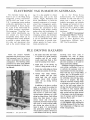
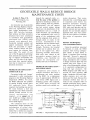
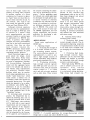
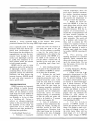
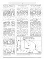
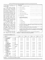
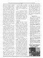
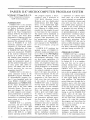
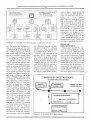
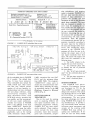
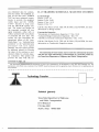
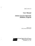
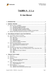
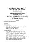
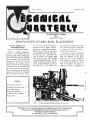
Vol. 4, Issue 3, October 1988. ,.all AN EXCHANGE OF IDEAS Editor: Kathleen M. Jones INNOVATIVE GUARD RAIL PLACEMENT by Steve Golding, P.E., and Kathleen Jones Division 10, Research Section District 11, Lufkin, is enthusias tic about a new method for con structing guard fences. During the 1988 construction season, the Dis trict contracted to have 18,946 feet of guard rail on SH 147 removed and replaced. The contract was let with an estimate of the percentage of reusable rail, but stipulated the use of new nuts, bolts, and posts . Marcus Construction Corporation, an out-of-state firm with a regional office in Cedar Hill, Texas, under- bid all the conventional-method operators with a highly efficient, innovative construction method. With a crew of four to five and a truck-mounted drilling and pile driving rig, this contractor was able to remove and replace 1000 feet of rail per day. (The average conventional-method crew of five might be able to remove and re place around 500 feet per day.) Reusable rail in the 18,946 feet was estimated at 80 percent. Mar cus' bid was 50 cents a lineal foot to remove old rail, and $9.00 a lineal foot to place new . Currently , many contractors drill or excavate holes much larger than the diameter of the posts, align the rail on jigs (hangers), then attach the posts to the rail and backfill the postholes. Often with this method, the posts are difficult to keep in alignment as INSIDE ... Pile Driving Hazards.... .. ..... J !Australian Electronic Tags .. .. 3 Ceotextiles Reduce Bridge Maintenance .. ........... 4 Troubleshooting HRWRs .. .... 7 Passer /1-87 ............ ...... .... 12 FIC.l: II Truck-mounted drilling and pile-driving rig. Published by the Texas State Department of Highways and Public Transportation, Transportation Planning Division, Research and Development Section, Technology Transfer Subsection P.O. Box 5051, Austin, TX 78763-5051. II 2 they are being backfilled; this sometimes results in poor align ment of the rail. Another problem with this method is that the posts settle unevenly over a period of a few months, pulling the rail out of alignment. The new method over corries both of these problems by aligning the rail first on hangers, pile driving the posts into holes near to; or slightly smaller than, post diameter, and then attaching the rail to the posts. Little or no backfilling is necessary. After each 25-foot section of rail is placed on a pair of jigs (hangers) in proper horizontal and vertical alignment, a truck with a trailer load of posts follows. A crew unloads four posts per sec tion to the back of the rail. Next in the sequence is the truck mounted drilling and pile-driving rig. The operator drives the rig along the guard rail, until the per son on the ground, who places the posts, signals to the operator to stop. The post placer helps the operator position the auger so it aligns with a bolt hole in the rail. A hole, slightly smaller than the post, is drilled. The post placer picks up a post and sticks a metal rod through the hole in the post. He then positions the post onto the posthole. The operator uses the pile driver on the rig to drive the post. The post placer stops him when the metal rod in the post comes to the correct eleva tion. The post placer removes the metal dummy and pushes the ac tual bolt through the post and rail. He hand-tightens the nut at the back. A third crew member fol lows with a power torque wrench tightening the bolts on the posts and lap slices. A fourth crew member checks the soil at the base of the posts, tamping it with a shovel when necessary. The procedure is very precise, with no time wasted trying to bolt a rail to a post that is too far away. It takes about one minute to drill the posthole, drive the post, and then bolt the post to the rail. District 11 videotaped seg ments of the construction method. Watching the videotape, through many consecutive post settings, it is obvious that this procedure worked very well. Every post was placed quickly and accurately, without a single post having to be pulled up. For more information, contact Mr. Walter Hearnsberger, San Augustine Resident Engineer, District 11, (409) 275-2541. A copy of the unedited, un-narrated video footage is available on loan from the D-10R Technology Transfer Library, TEX-AN 241-7644, (512) 465-7644. FIG.2: Aligning auger with rail hole. Drawing from videotape FIG.3A & B: Driving the post to correct elevation. 3 ELECTRONIC TAG IS MADE IN AUSTRALIA The electronic license tag af fixed to cars in the Hong Kong congestion pricing experiment (AITO:4 :86) was made in the U.K. A competing version seeking world-wide appl ications has now been developed in South Austra lia , a part of the world noted for its public transport innovations . The proprietary "TransiTag" elec tronic vehicle identification sys tem , consists of a fixed onboard transponde.r device which can be interrogated from remote locations to provide a unique vehicle iden tity code and operational data such as the current mileage read- ing. It is also possible to obtain variable data , such as the load content , weight, destination and driver identification , to build the essential components of a comput erized fleet management system . The electronic license plate makes possible the automation of fuel dispensing, weigh bridges, parking garage access and timekeeping. In the case of public transport and emergency services, the developers of the TransiTag system note that it can be interlocked with traffic light controllers to provide inter section priority for buses, ambu lances and police cars. As in the Hong Kong demonstration, the TransiTag transmits its code and data as it passes over a detector loop. A roadside interrogator unit decodes the message and converts it into a computer-readable format which can be sent over a phone or cable system to the fleet management mainframe. From AASHTO International Transportation Observer, Washing ton, D.C: The American A ssoci ation of State Highway and Transportation Officials, April 1987. Used by permission. PILE DRIVING HAZARDS There are certain hazards associated with pile driving of which field personnel must be aware in order to avoid injury or more serious consequences. The following safety precautions are taken from SDHPT Construction Bulletin C-8, Pile Driv ing Manual: ' 1. Be certain that boiler and steam or air lines are in good operating conclition and do not contin uously stand near them as they may fail causing serious injury. 2. Stand clear of the driving rig while it is being moved or set up. 3. Stand clear while piling are being hoisted into position for driving. 4. Always wear safety helmets, safety goggles and any other safety gear that will protect against Injury while working under the rig during driving operations. FIGURE I: Are you at risk? In addition to the above, working under a rig should be avoided by inspection personnel if at all possi ble. Pieces of concrete or steel have been known to spall from piling, driving helmets, hammers, etc. while piling are being driven. Such falling pieces have been known to cause serious injury and even death. Inspection personnel should arrange their work to avoid. working under pile driving rigs where the risk of injury is great. It is recommended that penetration readings be taken with the aid of a transit or level set up a safe clistance from the rig. Various methods have been used to accomplish this, such as taking readings from a gauge attached to the pile or hammer or by marking the pile with increments to be used for taking penetration readings. Sometimes it might be necessary to work within a cofferdam. If so, try to perform the necessary work or measurements from the area farthest away from the rig to avoid falling objects; but if at all possible try to perform all inspections from outside the cofferdam when driving opera tions are in progress. Ear plugs should be used when working within a cofferdam to prevent injury to the ears by the loud noises caused by driving. Stay alert amf.look for signs of failure or other hazards which may cause injury; if any are noticed, alert workers and any other persons of the danger; stop the driving opera tions if necessary until the hazard is removed. Play it safe! From SDHPT Bridge Tips, No. 1 (13 DECEMBER 1985), published by the Bridge Division (D-5) of the Texas State Department of Highways and Public Transportation. r 4 GEOTEXTILE WALLS REDUCE BRIDGE MAINTENANCE COSTS by John T. Price, P .E. beneath the approach slabs, i.e., Price and Company , Inc. Wyoming , MI treat the cause of the problem as An innovative use of geotextiles by the Wyoming Highway Depart ment has significantly reduced their bridge maintenance costs. Since 1983 , forty-five Interstate, State primary and State secondary structures have been constructed or retrofitted with geosynthetic reinforced soil (GRS) walls beneath each approach slab. Geotextile inclusion enabled soil support continuance beneath the slabs and prevented or signifi cantly reduced lateral soil pres sures against the adjacent abut ment walls. The result: (1) not one of the 90 approach slab-bridge deck junctions has required " level ing" to improve serviceability and safety , and (2) none of the expan sion joints have required replace ment due to closure as a result of abutment movement. PROBLEM IDENTIFICATION APPROACH SLAB Correcting bridge end "bumps" represented a costly maintenance program to the Wyoming Highway Department (WHO). For years, the WHO addressed this problem by placing leveling courses above the approach slabs . When required, mud jacking was used to fill voids between a slab and embankment soil. Both treatments offered limited success as con tinued maintenance was required - at an annual cost of over $1,600 per bridge wherever the slab/deck unconformity oc cu rred (1985 fi gu re ). The continued drain on the Department's budget prompted an investigation to review alter natives. The investigation con cluded that a method was required to prevent a loss in soil support rection alternatives. Their review indicated that a contributing agent to expansion joint failure was abutment movement resulting from lateral soil pressure. Since GRS walls could provide total lat eral soil restraint and were already planned for use beneath adjacent approach slabs, they were consid ered the best solution to elimina te this origin of expansion joint failure . opposed to mending a surface con dition resulting from the problem . Unfortunately, the soil support loss had several origins, among which were (1) densification of the embankment soils as a result of traffic vibrations, (2) consolidation of the embankment soils, and (3) piping of the embankment soils into the subgrade drain system or through joints or cracks in the structure . Consolidation of the foundation soils was deemed negli gible due to their type and strength. Therefore , the remedial method had to address three ori gins of soil support loss . After reviewing available alternatives , G RS walls were chosen as the preventative measure based on reliability, cost, flexibility (to account for site-specific con straints) and ease of installation. DESIGN TECHNIQUES AND CONSIDERATIONS Using the guidelines presented by Steward, et al.[l], the WHO analyzed walls having configura tions similar to those shown in Figure 1 (reprinted from working drawings) . Steward's approach uses conventional geotechnical design assumptions and is suitable to design structures both with and without wing walls . Figure 2 pro vides a three-dimensional schemat ic of a geotextile configuration for wing wall type structures. The WHO designed each GRS wall to account for local geometry (fi;If height, foundation soillrockslope, surface contours, etc.), soil con ditions and live loads. Because this analytical method does not ac count for the composite effect of multiple reinforcing layers, conser vatism inherently results. Full-scale l. PROBLEM IDENTlFICATlON EXPANSION JOINT Expansion joint closure or reduced movement had been a troublesome and costly problem for the WHO . At a replacement cost of approximately $25 ,000 for each device (1985 figure) and a frequency greater th a n expected , the WHO again reviewed the problem causes and available cor ' " (Min, ~ FIGURE 1: 10 cr.l af £ In~eri Representative wall configuration. 5 FIG U R E 2. Typical Layer of Fabric (Near side wing wall not shown for clarity). field research[2] verifies this con servatism. In essence, the analysis provides direction to the following unknowns: (1) number of rein forcing layers required; (2) tensile strength necessary for each rein forcement member; (3) length of each reinforcement member; and (4) distance between reinforce ment layers. These four design elements are mutually depen dent - altering one has an effect on the others. Once the wall ele ments are determined, the com posite structure of soil and reinforcement material is analyzed as a rigid body for resistance to rotational and sliding failures. Finally, a review of the foundation soil's bearing capability is made. While the Steward approach provides details of wall component placement and structural require ments, several incalculable benefits are derived from using GRS walls. Specifically, multiple reinforce ment layers significantly increase the overall fill stiffness[3]. With greater stiffness, better compaction is possible and less traffic-induced settlements result. The increased density also translates into greater shear strength for cohesionless soils. Therefore, loads are distrib uted more quickly and evenly, reducing differential consolidation. Geotextiles placed as shown in Figure 1 confine, separate and fil ter the embankment's cohesionless soils . Migration of particles into the subsurface drain systems or through joints in the structure is prevented. Therefore, GRS walls inherently prevent this contrib uting cause of soil support loss. GRS walls are normally con structed without the presence of abutments or wing walls; they have the capability to sustain all lateral soil pressures. However, soil movement is required to activate the reinforcement mem ber's tensile strength. Research[3] at Glenwood Canyon, Colorado, indicates that less than 3 inches of lateral soil movement is necessary to stabilize a 1S-foot high GRS wall in an unrestrained (no abut ment) condition . Since one of the WHD objectives was to achieve an unrestrained condition (no soil pressure on the abutment), 3-inch thick polystyrene panels were placed between the geotextile and abutment (or wing wall). The pan els would compress with lateral soil movement and reduce or eliminate soil pressure against the abutment and wing wall. CONSTRUCTION For both retrofitted and new structures, the abutment and wing walls were used as "forms" for constructing each reinforced lift. As shown in Figure 1, the founda tion soils were prepared by cutting a slope toward the abutment foot ing. An underdrain system (pipe and drain stone) was placed, bringing the fill height to approxi mately the height of the abutment footing top. Three-inch thick poly styrene boards were positioned on the soil side of the abutment and wing walls. With the styrene in place, the first geotextile layer was positioned. The re-embedment "tail" of the geotextile was tem porarily tacked to the polystyrene to allow subsequent fill placement and compaction. Granular fill was then placed and compacted to a depth equal to one-half the dis tance between the reinforcement layers, except immediately adja cent to the abutment and wing walls. At these locations, the full depth of fill (between geotextile layers) was placed. The embed ment "tail" was then positioned and the remaining fill added to achieve proper elevation (to the level of the next geotextile layer). This embedment "tail tucking" procedure was used to enhance geotextile-to-soil friction and thus reduce the possibility of a local reinforcement member "pull-out" failure. The sequence of geo textile-fill placement was repeated until the approach slab elevation was achieved. COSTS AND BENEFITS INVOLVED (/985 FIGURES) Once the foundation soils were prepared, the installed cost of the geotextile reinforced system was approximately $12,000 per bridge or $6,000 per end. For com parison, a conventional, un-rein forced approach slab embankment typically costs approximately $3,200. The $2,800 difference was attributed to additional granular fill requirements and geotextile costs as well as increased construc tion time requirements. Justification for this initial capital outlay resulted from elimi- ".. nation of the $1,600 annual main- r tenance cost for "leveling" at many locations. Public conve nience and increased safety contributed significantly to offset the cost differential. Finally, the elimination of the replacement of just one explansion },oint offset the increase in construttion cost of eight GRS walls . Therefore, geosynthetic reinforced soil walls were considered justified and have become the design alternative pre ferred by the Wyoming Highway Department for approach slab embankments. CONCLUSIONS Forty-five Wyoming bridges (90 approach slab embankments) have been constructed or retrofitted with geosynthetic reinforced soil walls since 1983. The structures 6 have withstood a wide range of internal and traffic loadings. Since the installation of the GRS walls, the Wyoming Highway Depart ment has not made repairs to any of the 90 embankments or ap proach slabs as a result of soil support loss . Similarly, the State has not been required to replace any expansion joints associated with these bridges . COMMENTS The use of geosynthetic rein forced soil walls is an effective means to reduce approach slab and expansion joint maintenance costs . The Federal Highway Administration and U .S. Forest Service as well as many State transportation departments recog nize GRS walls as a genuine tool for use by engineers. Since the ini tial WHO installations and the subsequent cost figures reported previously, more realistic (less conservative) analytical tools are now available which reduce the strength and embedment lengths of the reinforcement members. Therefore, significantly lower cost walls may be constructed. Geo synthetic reinforced embankments may be properly constructed by contractors inexperienced in this application. An update from the Wyoming State Highway Department's Chief Engineering Geologist, W.F. Sher man, P.E.: "We utilize the fabric reinforced design in areas where settlement is anticipated within the fill. We do not utilize the reinforcement where the settlement is in the foundation below the fill or where the fill material is not susceptible to settlement. "At the present time the Uni versity of Wyoming has instrumented an installation west of Cheyenne for the Dep artment. This project was completed last fall [1987] and we have received no definitive information at this time. " Dr. Tom Edgar of the Univer sity of Wyoming is the research contact for this project. The D-lOR Technology Transfer Li brary has been placed on a list to receive data on the project as it becomes available. REFERENCES 1. Steward, John E., Williamson, R . , and Mohney, John, Guide lines for Use of Fabrics in Construction and Maintenance of Low-Volume Roads, United States Department of Agricul ture , Forest Service, Portland, Oregon; June 1977 . 2 . Guido, V.A. , Chang, D.K., and Sweeney , M.A . , Bearing Capacity of Shallow Founda tions Reinforced With Geogrids and Geotextiles, Preprint Volume, Second Canadian Symposium on Geotextiles and Geomem branes ; Edmonton, Alberta; Septem ber 1985; pp. 71-78 . 3. Bell , J.R., Barrett, R.K ., and Ruckman, A.C ., Geotextile Earth Reinforced Retaining Wall Tests: Glenwood Canyon, Colorado , Transportation Re search Board; Washington, D.C.; January 1983. 4. Price, John T . and Sherman, William F., " Geotextiles Elimi nate Approach Slab Settle ment, " Public Works, Volume 117, No.1, January 1986, pp. 58-59. EDITOR'S NOTE The author of "Geotextile Walls Reduce Bridge Maintenance Costs, " John T. Price, is a well respected civil engineer specializ ing in Geotechnical Engineering. He presents either design or in formational workshops on geotextiles and geosynthetics . The design workshops are geared pri marily toward project engineers. The informational ones focus on giving a detailed introduction to the design and installation aspects of using geosynthetics . If enough Departmental personnel express interest, Mr. Price could come and give a workshop on usink geotextiles to reduce approaCh slab fill settling . If you are inter ested in such a workshop, call the TQ editor, Kathleen Jones at TEX-AN 241-7947, (512) 465-7947, and say so . Y. TROUBLESHOOTING HIGH-RANGE WATER-REDUCERS by Kathleen Jones 0-10 Research Section Technology Transfer Group INTRODUCTION High-range water-reducers (HRWR), also known as super plasticizers, are chemical admix .tures which can be added to portland cement concrete mixtures to produce high slump concrete , or to produce high strength (above 6000 psi) concrete, depending on the mix proportions. HRWRs increase workability by dispersing individual cement particles through the paste . Because they increase workability, superplasticizers are capable of reducing the water con tent of a concrete mix by 15 to 30 percent without reducing slump or of producing a high slump in con crete without changing the wa ter/cement ratio. HRWRs differ chemically from regular water re ducers. The three primary materi als from which HRWRs are made are: 1. sulfonated naphthalene formaldehyde condensates; 2. sulfonated melamine form aldehyde condensates; and 3. modified lignosulfonates . All superplasticizers must meet ASTM C 494 Type F or Type G standards . By definition, admix 7 tures of these types reduce the quantity of mixing water required to produce concrete of a given consistency by 12 percent or great er. Type F does not retard the set. Type G does retard the set [2]. At the moment, only Type F has been tested and approved by Ma terials and Tests Division (D-9). Although relatively expensive (the total cost of a superplasticizer may be as high as $4 .00 per yard of concrete in a typical 5-sack mix), superplasticizers can yield economic benefits in certain types of applications [1] . HRWR con cretes, in general, offer higher strengths and lower permeabilities than can be had with conventional concretes . Also , they are often more abrasion resistant [1]. HRWR admixtures should never be used as a substitute for good concreting practice , however. Good concreting begins with a good, plastic mix design. Avoid harsh, rocky mixes. Rocky mixes don't superplasticize well and will be prone to segregation, bleeding, and honeycombing . Optimum coarse and fine aggregate factors need to be selected and tested in trial batches using representative job materials . Another major problem which may be encoun tered using superplasticizers is un usually "rapid slump loss ," which really means a sudden loss of workability within what should be acceptable placing time . The rapid slump loss appears to be an inher ent difficulty with ASTM Type F admixtures . It can be controlled , but not eliminated, by some prac tical steps explained later in the "Guidelines" section. To encourage good concreting practice , the Department has in cluded the following data note on the special provision sheet to Item 437: "High-range water-reducers will be used o.nly to meet special requirements and will require the written approval of the Engineer on each specific project. A sat isfactory work plan for control shall be submitted by the Contrac tor for approval , and evaluation of • the concrete containing the admix ture will be performed by the En gineer." Certain guidelines must be followed and a work plan must be developed for each job (to cov er natural variations in chemistry of different mix materials and dif fering job conditions) to avoid ma jor problems associated with the use of HRWR. This article will give a brief account of some typi cal HRWR applications and will outline information and provide guidelines for developing a suit able work plan for its use. APPLICATIONS Some main applications of HRWR are: I. Adjusting strength. 1. Increasing the strength of a 4- to 6-sack concrete mix with out increasing cement content. The water-reducing capacity of superplasticizers is used to pro duce a high strength concrete of normal workability from standard, good quality materials (Fig. 1). 2. Producing workable, high strength concrete (greater than 6000 psi) with very low wa ter/cement ratio, with an increased cement content (a 7- to 9-sack mix), and with no exotic materials such as silica fume. Water content can be reduced by up to 30 percent. In fact , concretes with water/cement ratios as low as 0.28 have been designed and placed successfully [3 , p235]. Precasting of prestressed ele ments is an area where special high strength requirements often occur (Fig . 2) . High strength mixes achieve release strength ear lier allowing earlier form removal, resulting in increased production and reduced fuel costs associated with steam curing. II. Adjusting slump without increasing water content . 1. Producing high slump, normal strength concrete . The ce ment-particle-dispersing properties of superplasticizers enable the mix to be made more workable with out changing the water/cement ra tio . 2. Producing high slump, high strength concrete. Super plasticizers can be used with high strength mix designs to increase the workability from stiff through normal to extremely plastic. Fresh high slump HRWR con crete is cohesive and can be con solidated with limited vibration - two useful properties in a prestressed casting operation. High slump, high strength con- FIG URE 1: A possible application for stronger-than-average concrete: Bridge rails to contain and redirect 80,000 lbs trucks . 8 FIGURE 2: V-wing segmental bridge in San Antonio. Most precast, prestressed elements were cast using HRWR high strength concrete. crete is especially useful in bridge structures which have heavily con gested steel reinforcement. Re search shows that the addition of a superplasticizer can raise the steel concrete bond strength in both normal and lightweight concrete [3, p2S0]. Fine dispersion of ce ment particles makes the increase in bond strength possible. HR WR can be used in many applications such as the production of lightweight concrete , concrete containing fibers, fly ash concrete, pumpable concrete for underwater placement, and blast furnace slag concrete; however , HRWR should be used only when necessary to meet a specific need. TROUBLESHOOTING HR WR concretes are frequently more difficult to handle because they can suffer rapid loss of work ability. Do not attempt to correct rapid slump loss by the addition of retempering water, by over-vigor ous finishing, or by use of water as a finishing aid. Trying to achieve an adequate-appearing surface in this way will only harm the durability of the critical top quarter-inch. Try to avoid rapid slump loss and other problems by following these guidelines: • A voiding Rapid Slump Loss 1. Estimate a reasonable transit time from the location of the ready mix plant to the job site . Use this estimate to establish a time for the initial dose of superplasticizer to be added to the fresh concrete. (The HRWR is to be added to the concrete at the job site within a certain time, as specified by the work plan, to aid in controlling rapid slump loss.) [1]. 2. Add retarding admixture at the plant if the reasonable time for addition of HRWR is estimat ed at more than 30 minutes. 3. Evaluate the trial batch slump test results, plotting a slump-Ioss-versus-time and a tem perature-versus-time curve. Limit ready mix truck loads to a volume that may be placed and consoli dated within the time frame for continuing acceptable workability as determined by the slump-Ioss versus-time and the temperature versus-time curves. To ensure adequate mixing, it is recommend ed that the ready mix trucks will need to be limited to 7S percent of their rated capacity [7]. 4. Loss of workability is lessened at lower temperatures [3]. During hot we'ather, retarding ad mixtures should be used with superplasticizers. Retarders help offset rapid slump loss by slowing the initial set [1]. Also, if changing conditions threaten to raise the concrete temperature above the work plan's specified maximum, hot weather concreting measures have to be taken to ensure that the concrete mix temperature re mains at or below the maximum. S. Redose the fresh con crete with HRWR if it does not reach design slump with the initial dose (this does not apply to air entrained mixtures) . With the ex ception of air-entrainment , a second dose of superplasticizer will not harm concrete properties. It may, however, extend the setting times noticeably. This would not be a problem with formed fin ishes, such as columns [1]. The concept of a sequence of doses at specified intervals (determined during trial batching) is useful in avoiding rapid slump loss during hot weather HRWR concreting [3, p239]. 6. Plan placing and finishing operations for maximum efficiency. Quick, competent han dling avoids leaving concrete wait ing in the mixing trucks. The less time that passes, the less time the concrete has to stiffen. • A voiding Segregation, Bleeding, and Finishing Difficulties 1. Design a mix that is ~ propriately proportioned for the intended superplasticizer applica tion . To prevent bleeding in lean to medium cement-content mixes, an increase in sand-to-total-aggre gate is usually necessary. In rich mixes, the normal ratio is usually satisfactory , bu . if the trial batch is sticky and difficult to finish, a slight decrease in sand-to-total-ag gregate ratio may eliminate the problem [4, p33]. Failure to achieve an optimum fines content may result in segregation and ob vious bleeding [3, p230]. 2 . Use the minimum amount of HRWR needed to achieve the specified w/c ratio and slump . The dosage to attain a giv en slump will depend, in part, on the initial slump . Mixes with low intial slumps of 1 to 2 inch will require higher dosages of HRWR 9 than will mixes with greater initial slumps . In general , the slump gain _. increases as the amount of HRWR increases, up to a maximum effec tive dose. Past this dose, increases in superplasticizer do not yield more benefi t [3, p228]. Excessive amounts of HRWR, in addition to being uneconomical, may result in segregation, bleeding, and loss of entrained air [8]. Excess super plasticizer bleeding to the surface will leave an oily residue that will not· allow another layer of con crete to bond properly . The sur face of an over-superplasticized mix may also show unusual crust ing. 3 . Keep in mind that HRWR high slump concrete re sponds very quickly to vibration . Vibration should be kept to the minimum necessary for adequate consolidation or overvibration may result [8]. • A voiding Undesirable Chemical Admixture Interactions 1. Concrete must be thor oughly mixed before adding HR WR or the HR WR will be ab sorbed irreversibly, leaving only small amounts to act properly as a dispersant. Add any hold water specified by design before the ad dition of the HRWR . After the addition of hold water, the con crete should be mixed a specified minimum number of revolutions [1]. Introducing HRWR after all the mix water has been added in sures that the correct amount of admixture will be left in solution to cause dispersion and raise initial slump to the desired slump [1 ;3, p219] . 2. Be aware that naphtha lene-based superplasticizer can sig nificantly reduce the effectiveness of neutralized vinsol resin and oth er specifically developed air-en training agents. In high slump concrete, it is often more difficult to retain entrained air. If air loss is a problem, it may be necessary to reproportion the mix to achieve the desired results [1]. Maintaining Quality Control WORK PLAN DEVELOPMENT The main objective in developing a detailed work plan is to establish a procedure and prac tice that will allow the consistent production of superplasticized con crete in agreement with the con crete specifications and specific conditions of the job, including materials selection, proportioning, batching, mixing , and casting . The developed work plan should include the following [from reference 2 , unless oth e rwise indicated] : 1. Purpose/Reason for using a superplasticizer. Here , the con tractor will justify its use . 2 . Information relating to the materials and concrete mix de sign. Proposed procedure recom mends that the contractor/supplier should prepare and test small vol ume batches containing HRWR and record this information in a manner similar to Figures 4 and 5; specification slump range should be used . It is desirable that a SDHPT representative witness these tests. Note: . A small por table-type mixer capable of mixing enough concrete to . perform the tests outlined in . Figures 4 and 5 should suffice . Materials and Tests Division (D-9) recommends a mix- 1. Use approved D-9 sources to assure that cement, ag gregates, and admixtures have consistent physical and chemical properties. 2. Inspect all mixing trucks prior to use. Trucks with worn blades, build-up on mixing blades, or other deficiencies that will reduce mixing efficiency should not be used to mix HRWR con crete [8]. 3 . Disperse HRWR onto the bulk of the mix, rather than the blades of the mixer , by using a rigid extension attached to the dis pensing hose [1 ,2]. 4. Conduct intermittent slump and air content tests, moni toring fresh concrete temperature, and casting cylinders and/or flexural strength beams. These tests will detect a temperature rise in the concrete, and will ensure that minimum strength specifica tions are met [1]. 5. Mix the concrete thor oughly, for the amount of time specified by the work plan, after the addition of superplasticizer. Placement should begin immedi ately . 6. Use standard, good con creting practice throughout. Hypothetical Slump-Loss-Versus-Time Curve, concrete temp. 95°F, measurements taken every 15 minutes from initial addition ofHRWR. ~8 Desired Slump Range ~\.,. '. 6 .<:: t.> .5 ~ First Redose 4 E ::s en 2 Initial ~.-----. Slump. l Ratarder Added At Plant o Initial Dose of HRWRatJobSite 30 45 I • 60 Time Elapsed, mins. 75 90 Maximum Time Allowed By Specification FIGURE 3: For this mix at 95°F, with only one redose allowed, the placement time limit would be 80 minutes. r: 10 er also capable of operating at an agitating speed. 3. Batch design and equip ment. A copy of the batch design should be included. Construction form 309 may be used to show all the pertinent information. Pro posed procedure suggests that the contractor/supplier prepare and test at least one full-sized batch using the equipment and batch de sign to be used on the job . To ensure adequate mixing, recom mend the batch should be no more than 75 percent of the mixer capacity. SDHPT personnel should witness all tests, preferably with the project inspection team. 4. Botching sequence. Any admixtures to be added at the plant and their dosages, and HRWR dosage rate and addition method should be included in the work plan. When recommending the HRWR addition rate and method, the slump range in which the admixture will be added must also be identified . 5. Slump-loss-versus-time curve and temperature-versus-time curve. Include in the work plan I. General Data A. Project No ., Control No. , & County B. Structure Name(s) C. Structural Element(s) D. Contractor E. Concrete Supplier F. Cement Type and Brand G. Course Agg. Source a nd Grade H. Fine Agg. Source I. J. Admixtures (Brand Name) & Recommended Dosage Range I. Air 2. Retarder 3. Water Reducer 4. High Range WR Narrative on recommended charging sequence and mixing times at plant and job site, maximum batch size , dosage rates, maximum and desired slump, special procedures to control segregation. K. If pumping is proposed, the slump before and after pumping and the air content before and after pumping should be considered and documented. L. If multiple dosing with HRWR is allowed at site, this procedure should be modeled and tested on the full volume trial batch with appropriate air and slump testing , including air and slump loss with time. The re-dose dosage rate must be specified and included in the narrative. M . Include a graph showing the slump loss vs. time and concrete temperature . FIGURE 4: Outline for mix design using HRWR. II. MIX DESIGN USING HRWR (continued) BASE MIX TRIAL A. Course Aggregate B. Fine Aggregate C. Cement D. Water E. Admixtures 1. Air 2. Retarder 3. Water Reducer 4. High Range WR F. Cement Factor G. Workability Factor H. Cement Water Ratio I. Slump (initial) J. Air Content K Concrete Temperature L. Air Temperature M. Strength 1. 7 Day Beam 2 28 Day Cylinder N. Slump Loss 1. Initial + 15 min . 2. Initial + 30 min. 3. Initial + 45 min. o. Timeto Set P. Air Content I + 30 min . FIGURE 5: -- # TRIAL -- # TRIAL -- # TRIAL Ibs. Ibs. Ibs. Ibs. oz . oz. oz. oz. sacks/yards gal/sack in . % F F psi psi in. in. in. hrs. % Mix design using HRWR continued. '. -- # 11 that the concrete used to develop these curves be batched under the most critical temperature condi tions anticipated (Fig. 3). In order to have a meaningful curve, the slump and temperature should be taken every 15 minutes. The slump-loss-versus-time curve will be used to establish placement time limits for the anticipated maximum concrete temperature. Establishing placement time limits for a mix at a given temperature helps to eliminate any placement, consolidation, and finishing prob lems which may arise from the use of HRWR. Data provided on the curve will indicate the range of temperatures (the maximum tem perature down to 60°) and maxi mum placement time that the specific concrete can be handled adequately in the field. 6. Temperature control. The maximum acceptable concrete temperature must be given in the work plan. It must be based on standard specifications or slump loss-versus-time at the maximum anticipated temperature curve, whichever is lower. In trial batches, if one batch exceeds the anticipated maximum temperature, run a time-versus-temperature curve for that temperature and document the concrete's behavior. If the concrete does not show un usually rapid slump loss or finish ing difficulties, it may be possible to use the newly established curve as the maximum temperature. 7. Concrete strength. Com pressive or flexural strength, de pending on job requirements, should be performed on the con crete being used to develop the slump-loss-versus-time and tem perature-versus-time curves. 8. Mixing time . The mixing time/mixing revolutions prior to and after the addition of HRWR must be specified . 9. Redose. Any conditions that may require a redose of HRWR, if allowed, should be in dicated. Also include the redose dosage, permissible slump range , and the mixing time after redose. 10. Air content. Air content, if required, should be taken be fore and after the addition of HRWR. If redoses are allowed, it should also be checked after the redoses. work plan. The approved work plan, like a plan note, should su persede SDHPT highway specifica tions. Suggested guidelines and ideas for developing such a work plan have been outlined in this article. For more information, 11. Contractor's precon contact Mr. Gerald Lankes (0-9) : struction responsibilities . Speci fy T E X A N 241- 73 31, (512) that the contractor is to plan, 465-7331 ; or Mr. Berry English hold, and document a special (0-5): TEX-AN 245-5093, (512) preconstruction and training con 371-5093 . ference to discuss the results of testing, the proposed mix design, REFERENCES the anticipated site conditions, and I. Eckert, William C. and Carrasquillo , potential problems. SDHPT pro Ramon L. (Preliminary Draft), Re· ject personnel responsible for ma search Report 1117-2. Austin: Univer sity of Texas (CTR), June 1988. terial control are to participate. SUMMARY High-range water-reducers (HRWR), also known as super plasticizers, are chemical admix tures that can reduce water content in concrete mixes by up to 30 percent. They are used in the production of high strength (great er than 6000 psi) concrete of nor mal workability, high slump concrete of normal strength and high workability , and high strength, high slump concrete. They act by dispersing individual cement particles throughout the paste suspension. Analysis of har dened concrete made with super plasticizer often shows finer particles and denser structure within the cement paste. If properly proportioned and placed, concrete made with a HRWR is of good durability and low permeability. However, there are problems associated with the use of HRWR; careful consider ation of the intended application and job site must be made and, like any admixture, HR WR must not be used in place of good con creting practice . The problems of either segregation and bleeding or sticky, difficult finishing can be overcome by carefully adjusting the HRWR dosage and by care fully proportioning the mix (par ticularly selecting an optimum fines content). Other problems can be dealt with by following guide lines and by developing a practical 2. Lankes, Gerald D. "Admixtures for Concrete. " Paper presented at the 32d Annual District Laboratory and Engi neering Personnel Meeting, Abilene , Texas, March 23-24 , 1988. 3. Ramachandran, V.S. and Malhotra, V.M . " Chapter 4: Superplasticizers, " Concrete Admixtures Handbook. Park Ridge , New Jersey: Noyes Publica tions, 1984. 4. Schutz, Raymond J. "Proportioning Concrete for High Range Water Re ducers," Paper presented at National Readymix Association Concrete Troubleshooting Conference, Milwa u kee , Wisconsin , May 17-20, 1987. 5. Texas State Department of Highways and Public Transportation (TSDHPT) . Bridge Division. Concrete Construction Manual, Construction Bulletin C-I. Austin : TSDHPT, 1982. 6. TSDHPT. Construction Division. Con struction Mallual. rev. ed. Austin: SDHPT , 1986. ~ 7. TSDHPT. "Item 360.1, Water Cement Ratio," " [tem 420, Concrete Struc tures ," and "[tem 437, Concrete Ad mixtures. " 1982 Stalldard Specificatiolls for Construction of Highways, Streets and Bridges. Austin : SDHPT,1982 8. Whiting , D. and Schmitt, J. Durability of In-Place COllcrete Contaillillg High Range Water-Reduci"g Admixtures, NCHRP Program Re"port 296. Wash ington, D.C.: Transportation Research Board, 1987. Good Advice Before Doing Anything ... THI NK ~~ - - ,.. 'j.. -:- ~ .~ ~:~ r'·· • --~ ~' t. • •' " , I \ -·9 ~. ":>... 12 PASSER 11-87 MICROCOMPUTER PROGRAM SYSTEM by Edmond COp Chang, Ph.D., P.E. Texas Transportation Institute A& M University System INTRODUCTION PASSER 11-87 is the acronym for frogression Analysis and ~ig nal ~ystem ~valuation Routine. PASSER II was originally devel oped by the Texas Transportation Institute (TTl) for the Dallas Cor ridor Project. The Texas State Department of Highways and Pub lic Transportation (SDHPT) has sponsored the subsequent develop ment of PASSER II on both mainframe computers and micro computers [1]. The theory, model structure , methodology , and logic of PASSER 11-87 have been eval uated and documented. PASSER II has received widespread usage because of its ability to easily se lect multiple phase sequences by adjusting the background cycle length and progression speeds to find the optimal timing plans, such as cycle, green split, phase se quence, and offsets, that can effi ciently maximize the two-way progression bands [2]. PASSE R II -87 is the most re cently enhanced version of the PASSER II program. PASSER 11 87 microcomputer program Ver sion 1.0 was completed under the Texas HP&R 2-18-86-467 study , Enhancements to PASSER /1-84, by the Texas Transportation In stitute (TTl) of the Texas A&M University System. This n.ew pro gram was designed for ready use by traffic engineers and transpor tation professionals to optimize or to evaluate the isolated signalized intersection or coordinated arterial street system of up to 20 signal ized intersections. PASSER 11-87 is a powerful, easy-to-use, and user friendly sig nal-timing program for IBM PC/XT/ AT/386 or compatible microcomputers having the PC DOS or MS DOS 2.1 or higher diskette operating systems (DOS). • The program requires a micro computer with a minimum of 512K RAM (R a ndom Access Memory) and two double-sided double-density (OS DO) floppy drives, or one double-sided high density (OS HD) floppy diskette drive . However, it is highly recom mended that the program be used on hard disks for fast execution. The system will be distributed to SDHPT personnel with the main program , input preprocessor, out put postprocessor, optional help information, and microcomputer user's manual for the PASSER 11 87 microcomputer program system. PASSER 11-87 combines the updated version of PASSER II, advanced analysis procedures simi lar to those in the 1985 Highway Capacity Manual , and the latest microcomputer technology. There are three major applications: (1) isolated intersection timing eva lu ations, (2) progression signal tim ing optimization, and (3) "Existing Timing Evaluation" or "Simulation Evaluation ." The program assumes the isolated evaluation as the de fault if the input data pertain to only one intersection. On the oth er hand, this program assumes progression if the input data in clude more than one intersection in the system. In progression, PASSER 11-87 seeks to maximize two-way bands and minimize sig nal delay based on the combina tion of traffic volumes, saturation flows, and minimum phase times under a given cycle length range. To analyze an isolated intersec tion, traffic turning movements and intersection approach satura tion flow rates are needed. Mini mum phase times for each movement must also be provided. PASSER 11-87 can optimize the signal phasings ranging from the simplest two-phase operations to the most complex, variable se quence, multiphase coordination . The signal phasing is described on a "permitted" or "allowed move ment" basis. Up to four possible arterial phasings are permitted at anyone intersection, whereas each cross street can have only one of four possible phase sequences. In addition to the normal protected or permitted left turn phasing, it can further analyze the complicat ed permi tted/protected or protect ed/permitted "combined phase" left turn sequences. The system employs the most advanced high way capacity technology. There fore, PASSER 11-87 may also be used as a traffic planning or capac ity analysis tool if volumes , satura tion flows , intersection geometrics and signal timing are known [3]. PROGRAM FEATURES PASSER 11-87 has a complete stand-alone microcomputer user interface for the interactive arterial progression and intersection capac ity analysis [1]. It is an engineer ing tool that can be used to produce minimal delay and good arteri a l progression . TTl and SDHPT have designed the microcomputer input/output sys tem so that an engineer who is no ~ too familiar with a microcomputer can still effectively start the system to solve signal timing and evalu ation problems. The input/output process helps users through the in teractive query with data input guidelines and sets of help menus in the data input process. Routine data coding checks will help the users to modify the data without having to exit the PASSER 11-87 system. After all the input has been completed, the system exam ines the input data, automatically stores it in a data file,executes the program, and then allows the user to review or to print out spe cific output as needed. PASSER 11-87 (Fig. 1) com prises the most advanced micro computer technology with an intelligent, user-friendly menu in terface in the input/output proces 13 HPR 2-18-86-467 STUDY PASSER II -87 AI PROGRAM ON-LINE HELP MENU SYSTEM r=:1 a::::J r USE CURSOR KEY TO MOVE AROUND <CR> ORRETURN KEY <ESC> TO TOGGLE SCREENS ALT-C TO EXIT THE SYSTEM ~ ~ INPUT optimal signal tlmlllg plans for each intersection (INT.SUMY), a series of level-of-service evalua tibns for each phase (BEST.SOLN), total arterial sys tem performance (ART.MOE), signal controller phase interval set ting report (PIN.SET), and the optimal time-space diagram (TS.DIAGM), if requested. The implementation of the optimal timing plans can be greatly facili tated through the use of phase in terval tables with respect to the system master intersection for the microprocessor-based, traffic-actu ated signal equipment (Fig.2) [3] . FIGURE J: PASSER 11-87 Microcomputer system menu structure. sor . The system was developed so that it would accept all the exist ing PASSER II or PASSER II-84 data without requiring any manual user modification . The data can be entered or modified through either the full-screen, cursor keyboard, or mouse interface. The operator can exit the current state at any time by pressing the "escape" key. The built-in help windows are pro vided by pressing the FUNCTION KEY [Fl] OR [F2] . In addition, users can even tailor the content of the global help screen according to their own agency-specific re quirements through the use of the global PASSER 11-87 help menu by using the FUNCTION KEY [F6]. Two other utility functions , like those available in many com mercial packages, are also pro vided in PASSER 11-87 to assist users in providing efficient traffic analysis . The FILE DIRECTORY function can be reached at any time by pressing the FUNCTION KEY [F4] for reviewing and pro viding the needed file manage ment. More importantly, the EXTERNAL DOS SHELL func tion can be activated by pressing the FUNCTION KEY [FS] to al low users to reach the Diskette Operating System (DOS) com mand line interface level. The user can perform all the file mainten ance functions, such as formatting new diskettes, backing up files, and performing other analyses, without even having to exit from the PASSER 11-87 system. PASSER II-87 provides an ex ceptional list of output features . The output is headed by an echo of arterial parameters (COYER) , a listing of system embedded data (EMBED .DATA), an intersection input (INPUT.DATA), and an er ror report (ERROR .MSG). The optimized solution output provides a listing of the optimal timings for the arterial street (ART.SUMY), PROGRAM IMPLEMENTAT/ON The program permits the engi neers to interact with the overall analysis process while relieving them from the tedious and repet itive manual calculations. Several program runs and some engineer ing judgment in the selection of proper input parameters may be needed before the final signal tim ing solutions can be produced. In response to the user desire to modify the embedded input data used in analysis, new features have also been added to let users adjust PASSER 1\ -87 OFFSET REFERENCE OTHER INTERSECTING ARTERIAL MASTER INTERSECTION REFERENCE INTERSECTION CURRENT ARTERIAL U NDE~~ ANALYSIS REFERENCED MOVEMENT MOVEMENT6 r' MOVEMENT 2 REFERENCED PERIOD BEGIN, END. FIGURE 2: PASSER 11-87 offset reference . 14 PASSER 11-87 EMBEDDED DATA INPUT SCREEN Pretimed or Actuated (P or A) = P Ideal Saturation Flow = 1800 pcphgpl Analysis Period, T = 15 minutes Sneakers, S = 2.0 Phase Lost Time, L = 4.0 Left Turn P + P(A or R) = A LOS Delay Criteria : Total Delay, Multiplier M = 1.3 * M = 6.5 C : 25 * M = 32.5 E : 60 * M 78.0 * M = 19.5 D : 40 * M 52.0 F > 60 * M 78.0 > TexasA&M Analytical Model < Model Form: Negative Exponential Australian Analytical Model Univ.ofTexas Simulation Model Your Own Model Same Model Form A : B: 5 15 (vph) (sec) VO - Opp Sat Flow T -LTCriticalGap H - LT Headway SL = = = 1750 4.5 2.5 (sec) = Exponential Function of(VO, T, H) "p" for Pretimedr"A"~ o o r Actuated FIGURE 3: PASSER 1/-87 embedded data screen. STREET NAME 4 VOLUMES 566 SAT FLO 5250 MIN PHS 16 II 5 [5J 2 VOLUMES 88 SAT FLO 1700 MIN PHS 10 VOLUMES 267 SAT FLO 3500 MIN PHS 21 ] NEMA VEHICLE MOVEMENT MocKingbIrd / j c v 7[5J 43 1700 10 .J L r, , c VOLUMES 1114 SAT FLO 3500 MIN PHS 21 6 ARTERIAL NAME SK i I I man Avenue / .J r, VOLUM S 240 SAT FLO 1700 MIN PHS 10 3[5J I A 1 N < /1 > INTERSECTION , VOLUMES 51 1 [5J SAT FLO 1700 MIN PHS 10 1 /'5J 5250 16 6 TRAFFIC VOLUME CALCULATION LT BAY. "PROTECTED PHASE" OPERATION NEED: VOLUMES, SAT FLO. MIN PHS LEFT TURN TRAFFIC (VPH) = 86 FIGURE 4: PASSER 1/-87 movement data screen. all the embedded data in PASSER II, if needed. The default data (Fig. 3) have been prepared. These embedded data include the traffic control type, ideal satura tion flow rate, analysis period , number of left turn sneakers, in dividual phase lost time, combined left turn phase reference, delay level-of-service evaluation, total de I a y ad jus t men t factor, basic HCM delay criteria, permitted left turn models, and the recommend ed left turn model coefficients. Another new feature in PASSER 11-87 is the addition of the data input "ASSISTANT" function for assisting users to input the traffic movement-related information graphica lIy, such as the turning traffic movement volume (VOL- UME), saturation flow rate (SAT FLO), and the minimum phase time (MIN PHS). The program's "ASSIST ANT" allows users to analyze the movement-based infor mation freely, fOllowing the analy sis procedures similiar to the 1985 Highway Capacity Manual (HCM) (Fig. 4). LEFT TURN SIGNAL TREATMENTS Due ·to the need for assisting users in analyzing different left turn signal treatments under co ordinated progression analysis, PASSER II-87 has been signifi cantly enhanced . These improve ments include the data input procedure, input data structure, green split calculations, progres sion calculations, and program output evaluations. PASSER II-87 left turn input uses the minimum amount of input information to generate the possible left turn treatments as well as the allowable signal phase sequences. The input data was designed to simplify the user's input for '1nalyzing the var ious possible left turn signal treat ments. First, the program will ask the user to provide the needed in formation concerning the use of the protected left turn bay for the corresponding left turn traffic movements. Then, the program will automatically generate the ap propriate treatments according to the user's input for the different left turn and through traffic move ments. The intelligence imple mented in the PASSER 11-87 program will allow the user to de termine the proper types of left turn signal treatments from their input. The system will inquire and infer from the conditio'ns in the following steps: 1. Use traffic volume to dis tinguish the use of left turn bay; 2. Use minimum phase time to indicate the use of protected left turn phases; 3. Ask "Is left turn protected only?" for the combined phase op~ eration; and 4. Use the phase sequence to select "which" combined phase . SYSTEM SUMMARY The PASSER 11-87 Micro computer Environment System was developed by TTl for the Texas SDHPT to facilitate signal design and evaluation. The system was developed for use on the IBM PC/XTI AT/386 or compatible microcomputer. The new system has many advantages over the ex isting PASSER II-84 program be ing distributed [2]. It provides a very user-friendly menu interface, full-screen cursor movements, and accepts all the existing coded PASSER 11-84 data without re quiring user modification. If de sired, the user can freely modify /5 any embedded data for analysis, and the system will faithfully re port all the data used. PASSER 11-87 has been enhanced tremen dously to provide the graphical traffic input and the "ASSIS TANT" function to help users with the 1985 HCM capacity ana lysis . The system can analyze all the commonly available left turn signal treatments, either with or without protected left turn phases or protected left turn bays. The system can also investigate the operational effects of the "com bined phase," i.e., "protected plus permitted" or the "permitted plus protected" left turn signal phasings . The new system provides an improved scheme for allowing the input of the existing or user selected offsets for arterial capac ity evaluation . The system will provide the user with the im- D-13 TRAINING SCHEDULE, SELECTED COURSES Levell/Design 1, Oct. 3-7 2, Oct. 24-28 1, Nov . 14-18 2, Dec. 5-9 Session Session Session Session Call Mr. Ron Petter (0-13), TEX-AN 241-3093, (512) 465-3093, for more information on Design courses . Construction Inspection "Introduction to Construction Inspection 1," Nov. 14-18 " Advanced Bridge Construction Inspection," Dec. 5-9 "Hot Mix & Concrete Construction Inspection," Dec. 11-16 Call Mr. Dell Wood (0-13), TEX-AN 241-3094, (512) 465-3094, for more information on Construction Inspection courses. The mentioning of brand names used is strictly for informational purposes and does not imply endorsement or advertisement of a particular product by the Texas State Department of Highways and Public Transportation. Continued on page... 16 The information contained herein is experimental in nature and is published for the development of new ideas and technology only . Any discrepancies with official views or policies of the TSDHPT should be discussed with the appropriate Austin Division prior to implementation of the procedures. Tech Transfer Technical Quarterly Texas State Department of Highways and Public Transportation D-10 Research P.O. Box 5051 Austin, ,"Texas 78763-5051 16 PASSER 1/-87 Con't. from page 15 proved user-specified controller Phase Interval Setting (PIN .SET) report and an enhanced optimal Time-Space diagram (TSDIAGM) . A " Microcomputer User's Guide" has been written to be dis tributed with the program pack age. It was developed for those users who are already familiar with the PASSER II program and desire to use the PASSER 11-87 microcomputer program to analyze arterial signal system design prob lems [3J . Any questions concern ing how the PASSER II program operates or what type of data in put it needs will be best answered in the "PASSER II User's Man ual." Please address all written correspondence or requests to the State Department of Highways and Public Transportation, File D-18STO (PASSER 11-87), 11th and Brazos Streets, Austin, Texas 78701-2483, (512) 465-8353 or TEX-AN 258-8353. REFERENCES 1. Chang, E . c., C. J . Messer, and B . G. Marsden. Analysis of Reduced-delay Optimization and Other Enhancements to PASSER 11-80 - PASS ER -- Final Report, FHWArrX-84/50+375-IF. Col lege Station : Texas Transporta tion Instititute , April 1984. 2. "ADDENDUM, PASSER version 3.0, Microcomputer Environment System -- User Instructions ." Austin : Texas State Department of Highways and Public Transportation. September 1986 . 3. Chang, E . c., J . C. Lei, and C. J. Messer. Arterial Signal Timing Optimization Using PASSER 11-87 -- Micro computer User's Guide, FHWA/TX-88/467-1. College Station: Texas Transportation Instititute, July 1988. T2 STAFF Director: Cindy King (512) 465-7682 Ass 't. Director: Debbie Hall (512) 465-7684 Editorrrech. Writer: Kathleen Jones (512) 465-7947 Information Specialist: Jim Manning (512) 465-7644 Librarian: Liz Humphrey (512) 465-3082 Our TEX-AN exchange # is·241. - - - _ ._ - - - - - - - - - - - - - - - - - - - - - - - - - - - SECOND NOTICE The State Appropriations Act requires all state newsletters and other periodicals to present a notice in three consecutive issues indicating "That anyone desiring to continue to receive the publication must so indicate in writing. The agency shall furnish future publications only to those persons requesting." This does not apply to department employees who receive their issues through departmental distribution channels other than the U.S. mail. To remain on the mailing list for Technical Quarterly , all others must respond by returning the notice , properly signed and dated, to : t. Technical Quarterly Kathleen M. Jones P.O . Box 5051 Austin, TX 78763-5051 Signature Date ___________________________________ Address ___________________________________________________________________________________