1
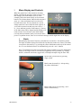
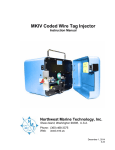
Northwest Marine Technology, Inc.
Air Driven Elastomer Injection System
User’s Manual
Table of Contents
1.
Introduction ........................................................................................................................ 1
2.
Contents of the Air Driven Elastomer Injection System ................................................. 2
3.
Control Box Description .................................................................................................... 3
A.
B.
C.
D.
E.
F.
G.
H.
I.
J.
K.
L.
M.
N.
4.
4
4
4
4
4
4
4
4
5
8
8
8
8
9
Handpiece Description ...................................................................................................... 9
A.
B.
C.
D.
E.
F.
5.
AIR COMPRESSOR QUICK CONNECT
AIR PRESSURE REGULATOR KNOB
BLOW-OUT PLUGS
DEBIT BUTTON
DRIP CONTROL KNOB
FRONT PANEL LED
HANDPIECE CABLE CONNECTOR
HANDPIECE AIR QUICK CONNECT
MENU DISPLAY AND CONTROLS
ERROR MESSAGES
ON/OFF BUTTON
POWER CONNECTOR
TOKEN PORT
VACUUM VENT PORT
CYLINDER BODY
FINGER SWITCH
HANDPIECE AIR HOSE
HANDPIECE CABLE
PISTON
SYRINGE HOUSING
9
9
9
9
9
10
Equipment Assembly....................................................................................................... 10
A.
B.
C.
D.
E.
ASSEMBLING THE HANDPIECE
SETTING UP THE AIR DRIVEN ELASTOMER INJECTOR
MIXING ELASTOMER FOR THE AIR DRIVEN ELASTOMER INJECTION SYSTEM
STORING VIE
RELOADING ELASTOMER
10
12
15
16
16
6.
Maintenance ..................................................................................................................... 17
7.
Disinfection....................................................................................................................... 17
8.
Repairs .............................................................................................................................. 18
9.
Troubleshooting/FAQs .................................................................................................... 18
10.
VIE Documentation .......................................................................................................... 19
11.
Contacting NMT ................................................................................................................ 20
GEV 02.2014
iii
1.
Introduction
The Air Driven Elastomer Injection System (ADEIS) was developed to improve accuracy, speed, and
ease of applying Visible Implant Elastomer (VIE) tags. Tag application rates as high as 600 animals per
hour are obtainable by a skilled operator using this system. VIE tags are implanted beneath transparent or
translucent tissues but remain externally visible. VIE tags are widely used for marking fish, crustaceans,
reptiles, and amphibians. VIE is a biocompatible,
two-part material that is mixed immediately before
use and then injected as a liquid that cures to a
pliable solid. VIE tags are ideal for batch
identification, but by combining different colors,
multiple tags per animal, and multiple tag
locations, many individual codes can be created.
VIE is available in six fluorescent colors (red,
orange, green, yellow, pink, blue) and four nonfluorescent colors (brown, black, purple, white).
The visibility of the fluorescent colors is greatly
enhanced with Northwest Marine Technology’s
(NMT) VI Light.
Proper color selection is a vital part of good
experimental design. Your choice depends on how
much contrast you need with the background
pigmentation and how many different colors you
VIE in ambient light (left) and illuminated by
require. Certain color combinations can be difficult
the VI Light (right).
to distinguish. In particular, we do not recommend
that green and yellow be combined in a study
because they are difficult to distinguish when fluoresced or when placed under pigmented tissue. Please
contact Biological Support (email: [email protected]) if you would like assistance with your project.
Before using Visible Implant Elastomer, available reference materials should be reviewed. We
recommend the VIE Project Manual which along with many other references can be found at
(www.nmt.us). If references are lacking, experiments to evaluate suitable tag locations, retention rates,
and tag visibility should precede applied uses.
Most clear or translucent tissue is a suitable target if there are
no associated pores or cavities through which the material can
exit. The adipose eyelids of salmonids and some other fishes,
as well as the spaces between fin rays are examples of
potential targets. Other possible targets are along fin margins
of flatfish, and the abdominal area of shrimps. Elastomer tags
can be placed under pigmented skin where they are difficult to
see in ambient light, but quite visible when fluoresced.
GEV 02.2014
1
2.
Contents of the Air Driven Elastomer Injection System
Supplies provided with the purchase or rental of an ADEIS:
•
•
•
•
•
•
•
•
•
•
•
•
Control box (4.25” high x 8” wide x 8” long)
Power supply. NMT can supply either a domestic or international power supply based on your
local power needs.
Handpiece
Multiport hose
Distribution hose (10’)
Water separator
Female quick connect fitting (Hansen 3000)
Safety goggles
Warning: Wear safety goggles whenever operating or working near the ADEIS.
VI Light. For rental units, this light must be returned with the rest of the rental equipment. VI
Lights can be purchased from NMT if they are needed for tag recovery.
Warning: Do not look directly into the VI Light. Do not shine the light into the eyes of others.
Keep out of reach of children.
Sharps container for used needles (supplied with a purchased unit only)
VIE Color Standard
Instruction manual
The approximate shipping weight of all supplies for one unit is 18 lbs.
Supplies you must purchase separately from NMT:
•
Token charged with tag credits. The number of tags the ADEIS can dispense is controlled by the
number of “credits” purchased. These credits are stored on a token. One credit is removed each
time the ADEIS is cycled (i.e. every time the tag injection button is pressed). An appropriate
amount of VIE elastomer material, injection syringes and mixing supplies are provided with the
charged token. Each token is programmed with a small number of extra “credits” to account for
normal operational waste of elastomer.
Supplies you must provide:
•
2
Air compressor – NMT recommends the following as minimum system requirements. Please
contact us with any questions about air compressor capability.
o Two gallon air tank.
o Air delivery capacity of 1.9 cubic feet per minute at 80 psi.
o Note: A water separator (provided) must be used with this equipment. Failure to do so
may damage the control box and will void the warranty.
GEV 02.2014
3.
Control Box Description
Figure 1: Control box for the
Air Driven Elastomer
Injection System
Token Port
Air Compressor
Quick Connect
On/Off
Button
Drip Control
Knob
Handpiece Cable
Connector
Air Pressure
Regulator Knob
Power
Connector
Debit Button
Menu Display
Control
Buttons
Vacuum
Vent Port
GEV 02.2014
Front Panel LED
Handpiece
Air Quick
Connect
3
3.
Control Box Description
A.
Air Compressor Quick Connect
This quick connect is used to attach the hose from the air compressor to the control box.
B.
Air Pressure Regulator Knob
This knob is used to control the air pressure in the control box. Pull the knob out to turn it, then
press it in again to lock the pressure at the desired level. The air pressure should never exceed 80
psi. Doing so will void the warranty and could damage the unit and cause injury.
C.
Blow-out Plugs
(Not pictured). These two white plugs on the bottom of the control box prevent too much pressure
from building up if an internal component fails. When properly installed, both plugs would be
flush with the bottom of the control box. If either plug is blown out of its hole, water can enter the
case and damage the electronics. If the machine appears to be functioning correctly despite a
missing plug, you can continue to use it, but you should keep it out of any water and return it to
NMT for repair as soon as is convenient. If the blow-out was the result of an internal component
failure, the machine will likely not work correctly, and you will need to return it to NMT for
repair before using it again. Please contact us if you need assistance.
D.
Debit Button
The yellow debit button is used to remove one injection cycle from the batch count each time it is
pressed. This function is a convenient way for the machine operator to maintain an accurate count
of the number of animals tagged should it be necessary to re-tag an animal or load a new syringe
of elastomer.
E.
Drip Control Knob
The drip control knob provides a way to limit the amount of elastomer that drips from the needle
tip between injecting animals. A slight vacuum is created in the machine by turning the knob
counterclockwise. The vacuum is turned off when the knob is turned fully clockwise. A hissing
sound can be heard when the vacuum is being applied.
F.
Front Panel LED
The red LED on the front of the control box lights each time the machine is activated with the
finger switch. It stays on for as long as the finger switch is pressed or for the length of time set in
the Timed mode.
G.
Handpiece Cable Connector
This cable connector is used to attach the handpiece cable to the control box.
H.
Handpiece Air Quick Connect
This quick connect is used to attach the clear hose from the handpiece to the control box and
delivers compressed air to the handpiece.
4
GEV 02.2014
I.
Menu Display and Controls
When the control box is first turned on, the menu
display will show the program version (version 5 in
this example) and serial number (194-01 in this
example). Below the menu display are four control
Scroll
button
buttons. The leftmost button, marked with an upward
arrow (↑), is the scroll button and is used to move
between menu items. The next buttons are used to
change numerical values within the menu options. If
you scroll to a menu item and press one of the (←, +
or –) keys and then press the scroll button (↑), the rest
of the menu items will be skipped and the display will
return to batch. You will not see the initial display
(version and serial number) until you next turn on the
power. If a problem occurs, there are several error messages which might show on the display.
i.
Batch
Batch displays the count of injector cycles that have occurred (i.e. the number of times
the finger switch has been pressed) since the last time the counts were cleared. The batch
count can be decreased by 1 by pressing the yellow debit button on the top of the control
box. To reset the batch count to 0, simultaneously press the + and – buttons.
Note: To maintain an accurate count of the fish tagged, remember to use the debit button
whenever the finger switch is activated but a tagged fish is not generated (e.g. loading
needles, accidental activations, tagged culls, or multiple attempts to tag the same fish.)
Injector has cycled 6 times by pressing
finger switch.
Batch count decreased by 1 after pressing
the yellow debit button.
Batch count reset to 0 by pressing + and –
buttons simultaneously.
GEV 02.2014
5
ii.
Credit
Credit displays the number of credits (i.e. control box injection cycles) in the machine
and in the token mounted in the token port. The number in parentheses is the number of
credits available on the token. The number outside the parentheses is the number of
credits stored within the control box. During normal tagging (with a token inserted into
the token port), the control box automatically draws 100 credit cycles from the token
whenever it’s balance is less than 100. If no token is present or if the token is exhausted,
the display will begin to flash and will stop operating when the credit cycles reach zero.
A charged token will be necessary to continue tagging.
Several machines can share credits from one token by transferring credit cycles (using the
+ button) from the token into the control box. Each time the + button is pressed, 100
credit cycles are transferred. Similarly, the – button will remove 100 credit cycles from
the control box to the token each time it is pressed. Holding either of these buttons down
will cause a continuous credit cycle transfer. Once the desired number of credit cycles is
reached, the token can be removed and used on another machine.
Note: Never remove the token while transferring credit cycles. To do so risks damaging
the token and loss of credit cycles.
To remove the token, grasp the black plastic tab of the token and carefully pull up. Once
removed, the display will only show the number of credit cycles held in the control box.
Occasionally, the black plastic tab will come loose leaving the token stuck in the token
port. If this happens, use a small flat-tipped screwdriver to gently spring it loose. It
should then easily snap back into the plastic tab and be ready for further use.
With the token in the token port, the display shows
that there are 69,700 credits on the token and 192
credits in the control box.
100 credits have been removed from the token and
added to the number of credits in the control box.
With the token removed from token port, the display
shows how many credits are left in the control box.
iii.
Pressure
Pressure displays the air pressure that the control box’s internal regulator exerts on the
elastomer injector piston. Pressure is regulated using the air pressure regulator knob. The
air pressure regulator knob is locked when pushed in. To adjust the pressure, unlock the
air pressure regulator knob by pulling it out; rotate it clockwise to increase pressure or
counterclockwise to decrease pressure. Rotate the knob until the desired pressure is
6
GEV 02.2014
displayed on the control box panel, lock the knob. For most applications, 40 psi to 60 psi
is recommended. The air pressure setting and the injection duration (controlled by using
Timed, see below) determine the amount of material injected each time the finger switch
is pressed.
Pressure adjusted to 50 psi
Safety Warnings:
• Never exceed 80 psi. Doing so will void the warranty and could damage the unit and cause injury.
• Even when disconnected from the air compressor, the control box can still hold some pressure.
Failure to ensure that the air pressure to the control box is off may lead to injury.
iv.
Timed
Timed displays how long air pressure will be applied to the handpiece piston and
therefore, how long elastomer will be injected once the finger switch is activated. If the
display reads “Timed: No”, the flow of elastomer will be continuous as long as the finger
switch is being pressed. Push the + button to switch to the “Timed: Yes” mode. The set
time durations available for “Timed: Yes” range from 0 to 9.999 seconds.
Elastomer will flow for as long as the finger switch
is pressed.
When the finger switch is pressed, elastomer will
flow for 0.2 sec.
If “Timed: Yes” is set to 0.00, no elastomer will
flow when the finger switch is pressed, but a credit
will be removed from the control box.
The timer setting can be changed by pressing the left arrow button (←). This will cause
the rightmost digit to flash indicating that it is ready to change. This digit can be
increased or decreased using the + or – buttons. Continue to change the other digits using
the ←, + and – buttons. Although typical injection times are less than a second, four
digits are available.
v.
Total
Total displays the total number of times the machine has cycled since it was built. This
count cannot be altered. It is used by NMT when servicing a control box.
The control box has cycled 145,908 times since it
was built.
vi.
Token
Token displays the token identification number if there is a token in the token port.
GEV 02.2014
7
The token in the control box is identified as
number 9.
J.
Error Messages
These displays indicate that something has gone wrong during normal operations. If you cannot
solve your problem using this manual (see troubleshooting), please call our Technical Support at
360-468-3375 or e-mail [email protected].
vii.
?Credit Lost?
Credit lost indicates that the control box lost contact with the token in the middle of a
credit transfer and 100 units of credit may have been lost. This error can be avoided by
allowing the token to rest for several seconds after being active and before removing it
from the token port. If this happens call technical support at 360-468-3375.
viii.
Power Down
Power down indicates that the flow of electrical power temporarily became weak or was
briefly interrupted but did not go off completely and so did not reset the machine. This
message will clear itself and the machine will return to service after several seconds.
Turing off the power and then on again will also clear this message. The control box has
a memory unit which preserves its settings when the power is off.
ix.
Memory Weak
Memory weak indicates that the memory unit in the control box has given early warning
that it may fail. The control box will still function properly once this error message has
been displayed and may or may not reappear when it is turned off and then back on. Once
this message has been observed, you should immediately contact NMT (360-468-3375,
[email protected]). If not serviced soon, the memory will fail and the machine will not
operate properly.
x.
Memory Failed
Contact NMT immediately (360-468-3375, [email protected]) and return the control
box for service. It will not function properly once this error message has been displayed.
K.
On/Off Button
This button is used to switch the power to the control box and handpiece on and off.
L.
Power Connector
This power connector is used to attach the cable from the NMT power supply to the control box.
M.
Token Port
The number of tags the control box can dispense is controlled by the number of “credits”
purchased. These credits are stored on a token which must be inserted into the token port before
tagging. One credit is removed each time the finger switch button is pressed. An appropriate
amount of mixing supplies and VIE material are supplied with the token. Each token is
programmed with some extra “credits” to account for normal operational waste and set up.
8
GEV 02.2014
N.
Vacuum Vent Port
Air vents through this port when the drip control knob is turned counterclockwise and a vacuum
is being applied.
4.
Handpiece Description
Finger Switch
Handpiece Air Hose
Handpiece Cable
Syringe Housing
Piston
Handpiece for the Air
Driven Elastomer System
A.
Cylinder Body
The cylinder body provides an airtight fit with the piston. Compressed air comes into the body
through the hose, puts pressure on the piston which then pushes elastomer from the syringe into
the needle.
B.
Finger Switch
The finger switch controls the flow of elastomer. Each time it is pressed, compressed air will
force elastomer from the needle tip. If the timer is set (see Timer), elastomer will be injected for
the set time. If the timer is set to NO, elastomer will be injected for the entire time the switch is
pressed. One credit is removed each time the switch is pressed. If the timer is set to YES 0.00,
no elastomer will flow, but one credit will be removed.
C.
Handpiece Air Hose
This hose delivers compressed air from the control box to the cylinder body. It is connected to the
control box by the handpiece air quick connect.
D.
Handpiece Cable
The cable controls activation of the finger switch. It is connected to the control box at the
handpiece cable connector.
E.
Piston
Pressure from the compressed air pushes the piston into the syringe and forces elastomer out of
the needle.
GEV 02.2014
9
F.
Syringe Housing
The syringe housing holds the syringe of elastomer.
5.
Equipment Assembly
A.
Assembling the Handpiece
Safety warning: Do not connect the handpiece cable or air hose to the control box until it is completely
assembled. Doing so may lead to an accidental discharge of air pressure which could cause the syringe
housing to shoot off resulting in injury.
1. Disconnect the handpiece from the handpiece air
hose.
2. Unscrew the syringe housing by holding the syringe
housing stationary in one hand while rotating the
cylinder body counterclockwise. Remove the piston.
3. Fill a 1.0 ml injection syringe about 1/2 full of
elastomer (see mixing instructions in Section 5C).
Special care should be taken to avoid an air gap
between the piston and the elastomer. This can be
accomplished by continuing to discharge elastomer
into the injection syringe while withdrawing the 12
ml loading syringe. An air gap will cause the
elastomer to ooze from the needle tip between tag
cycles resulting in waste and slower tagging.
4. Insert the metal piston into the syringe until the
elastomer has reached the syringe tip. The maximum
fill level is 0.65 ml. Eject any excess elastomer. If
overfilled, the cylinder body and syringe housing
will not thread together properly.
5. Securely attach a needle to the injection syringe.
10
GEV 02.2014
6. Insert the assembled injection syringe into the syringe
housing insuring that the injection syringe wings are
properly seated into the wing grooves.
Observe how the injection syringe mounts into the wing
grooves of the syringe housing. With this in mind, adjust
the needle tip bevel to accommodate each tagger’s
preference. This orientation will vary depending on how
the handpiece and animal to be tagged are held. It may be
helpful to tag a few animals to determine the preferred bevel orientation.
To adjust the bevel, remove the injection syringe from the syringe housing and adjust the
orientation of the needle tip bevel. Do not adjust the needle while still loaded in the syringe
housing because this can loosen the needle. Reload the injection syringe and retry. When satisfied,
note the needle position relative to the wings of the syringe or some other syringe feature (e.g. the
bevel was in line with the center of one of the syringe wings). This will assist with rapid loading of
subsequent syringes.
7. Check that there is silicone lubricant on the o-rings
on the piston. Insert the piston base into the cylinder
body until there is resistance then attach the
handpiece air hose to the back of the cylinder body.
This releases the air pressure on the piston so that it
will slide all the way into the cylinder body.
8. Hold the syringe housing and screw the cylinder
body to it. The air hose connection fitting will rotate
so the air hose will not tangle.
9. Continue with steps 8 through 10 of the instructions for “Setting up the Air Driven Elastomer
Injector”, next section.
GEV 02.2014
11
B.
Setting up the Air Driven Elastomer Injector
1) Plug the power supply directly into a grounded
power outlet. Attach the black connector at the
end of the power supply cord to the power
connector on the back of the control box. Do not
turn the power on.
2) Ensure that the air pressure to the control box is
off (i.e. that you haven’t connected the
compressor yet!). Then:
a) Unlock the air pressure regulator knob by
pulling it out.
b) Turn the air pressure regulator knob
counterclockwise as far as it will go.
c) Lock the air pressure regulator knob by
pushing it in.
12
GEV 02.2014
3) Attach the water separator to the air compressor.
Compressor
4) If you are using a single control box, attach the
distribution hose (10’) to the water separator. If
needed, an extension hose can be attached
between the water separator and the distribution
hose.
5) Up to12 control boxes can be used with a single
compressor. Attach the multiport hose to the
water separator. Then attach the distribution
hoses to the connectors on the multiport hose. If
needed, an extension hose can be attached
between the water separator filter and the
multiport hose, or between the multiport hose
and the distribution hose.
Water
Separator
Multiport Hose
Distribution
Hose
6) Attach the distribution hose to the air
compressor quick connect on the back of the
control box.
7) Insert a charged token into the token port on the
side of the control box.
8) Attach the completely assembled handpiece (see
section 4 for instructions) to the control box by
connecting the clear air hose to the handpiece air
quick connect on the front of the control box and
the black handpiece cable to the handpiece
connector on the back of the control box.
GEV 02.2014
13
9) Turn on the power to the control box using the
green on/off button.
10) Set the air pressure and activate the finger
switch.
a) First, set the air pressure to 20 pounds psi as
follows:
i) Cycle the control box menu to
“pressure” using the up arrow key (↑).
ii) Unlock the air pressure regulator knob
by pulling it out.
iii) Turn the air pressure regulator knob
clockwise to increase the pressure until
20 psi is reached.
iv) Lock the air pressure regulator knob by
pushing it in.
b) Press the finger switch once to engage the
handpiece piston.
14
GEV 02.2014
11) Increase the air pressure to a normal operating level between 40 psi and 80 psi. (Unlock the
air pressure regulator knob by pulling it out; set the air pressure to the desired level; relock
the air pressure regulator knob by pushing it in.)
Most applications can be accomplished with a moderate pressure setting (60 psi).
Typically, cold environments require lower pressures (50 psi to 60 psi) than hot
environments (60 psi to 70 psi).
As the elastomer begins to cure, it will become more viscous and the rate at which it passes
through the needle will decrease. It may be possible to extend the working time by increasing the
air pressure. However, NEVER exceed 80 psi. Doing so may cause equipment failure and injury.
C.
Mixing Elastomer for the Air Driven Elastomer Injection
System
An appropriate amount of elastomer and mixing supplies is supplied with each token/credit cycle
purchase. These directions must be followed accurately to insure proper curing of the elastomer
tags and optimal tag retention.
Contents (the amount of each item will vary depending on the number of credit cycles/tags
purchased)
• Token with purchased amount of credit cycles (plus extra credit cycles for setup and syringe
changes)
• Colored elastomer packaged in 6 ml syringes with blue caps
• 15 ml jar containing 1 cc of curing agent per 6 ml syringe of elastomer.
• Wooden stirring sticks
• 12 ml loading syringes
• 1 ml injection syringes
• Needles
1. Before mixing, set the jars of curing agent upright for 5 minutes so that the curing agent
settles to the bottom of the jar. Dispense all of the material from a 6 ml syringe (the colored
elastomer) into the 15 ml jar with the curing agent. Use a wooden stirring stick to thoroughly
mix the elastomer for 1 minute; scraping the sides will help ensure the elastomer is well
mixed.
2. Hold the 12 ml syringe with the tip down and pour in the mixed elastomer. Start the plastic
syringe plunger into the 12 ml syringe; turn the syringe tip up and let the elastomer settle
against the plunger. Once the elastomer has settled, press the plunger upward to remove all
air leaving only elastomer. Wipe the tip of the syringe clean.
3. Fit the tip of the 12 ml syringe tightly into the barrel of a 1.0 ml injection syringe. Hold the
injection syringe nearly horizontal and load the syringe as close to the opening (opposite the
needle end) as possible to facilitate removal of air. Fill the injection syringe about ½ full.
Additional injection syringes can be filled at this time. At room temperature (70 ˚F) the material
will provide about 1 hour of working time. Because the curing process is heavily temperature
dependent, you can greatly extend the working time by putting the additional syringes or stock
solution in the refrigerator or freezer until you are ready to use them. Smaller amounts of
elastomer can be mixed; refer to Instructions for 10:1 Visible Implant Elastomer on our website
at www.nmt.us.
GEV 02.2014
15
D.
Storing VIE
The shelf life of unmixed elastomer is at least 12 months from the date of purchase when properly
stored. NMT recommends that unmixed VIE be stored in a refrigerator to ensure constant
temperature. If this is not available, store the unmixed VIE in a cool, dark place. Do not freeze
unmixed VIE. Exposure to fluctuating temperatures, such as on the dashboard of a car, will
decrease the shelf life. Prolonged exposure to sunlight may fade the color. The VIE Color
Standard should also be stored out of direct sunlight.
Elastomer components older than one year may still be useable. You can test this by mixing a
small quantity and observing whether it cures properly. Thoroughly mix a small quantity of the
two components. If it remains workable for about 45 to 60 minutes at room temperature and has
cured to a rubbery solid within 24 hours, the material is useable. Otherwise, discard it and contact
NMT.
E.
Reloading Elastomer
When the rate of tagging drops below acceptable levels or tag quality diminishes (e.g. tags appear
thin and stringy), discard that syringe and reload with some VIE from either an “on ice” or freshly
mixed stock. Please refer to the instructions for mixing elastomer, above.
1. Turn off the power to the control box using the
green on/off button.
2. Disconnect the handpiece air hose from the
control box.
Safety Warning: Failure to turn off the power and/or
disconnect the air hose from the control box may
lead to an accidental discharge of air pressure which
could cause the syringe housing or tag needle to
shoot off resulting in injury.
3. Disassemble the handpiece.
a. Disconnect the handpiece from the
handpiece air hose.
16
GEV 02.2014
b. Hold the syringe housing firmly in one hand
while rotating the cylinder body counter
clockwise.
c. Once the threads have separated, pull the
cylinder body and the syringe housing apart
and remove the injection syringe with needle
and piston. Occasionally, the injection
syringe will stick in the syringe housing. It
can be dislodged by pushing down at the
base of the needle against a flat surface such
as the edge of a table or flat edge of a screw
driver.
d. Remove the piston from the injection syringe
and clean all of the elastomer residue from
the piston. Discard the injection syringe in an
appropriate container. Dispose of the needle
in the sharps container.
4. Continue with step 4 though 10 of the instructions for “Assembling the Handpiece”, above
in section 1 of Equipment Assembly.
6.
Maintenance
At the end of each tagging day, the control box and handpiece should be thoroughly wiped down to
remove any elastomer or dirt that has accumulated. Disinfectant hand wipes are effective at this task. The
handpiece should be disassembled and cleaned. Q-tips are useful to clean inside the handpiece syringe
housing. Any cracked or worn o-rings should be replaced to prevent elastomer leaks (and big messes!).
Carefully use a razor or scalpel blade to cut the old o-ring off making sure not to knick the piston and
slide a new o-ring into its place. Lubricate the o-rings with silicone. At the end of the tagging project, all
the equipment should be thoroughly cleaned and disinfected before removal from the tagging site.
Follow the manufacturer’s instructions for maintaining the compressor. This usually involves releasing
stored air and draining accumulated moisture from the holding tank.
7.
Disinfection
The possibility of spreading animal diseases between culture facilities and watersheds is of concern to
both the customer and Northwest Marine Technology. Although NMT is unaware of any cases where this
tagging equipment, moved between locations, served as a vector in spreading disease, the consequences
of such occurrences call for stringent preventative measures. Disinfecting procedures should also be
implemented between groups of animals within a facility. Tagging should not be conducted during a
severe outbreak of disease.
GEV 02.2014
17
Before using any disinfectant, please read and understand the Materials Safety Data Sheet (MSDS) for
each product. Be sure you have and use the proper safety equipment as prescribed by the MSDS.
We recommend using a chlorine solution for disinfecting the Air Driven Elastomer Injection System.
Commonly used sources of chlorine are calcium hypochlorite (HTT) and solutions of sodium
hypochlorite (bleach). Household bleach standard solution is usually about a 5% concentration. To
achieve the proper concentration requires diluting 1 ounce of bleach into 2 gallons of water (1:250).
Stronger solutions may be available at animal rearing facilities so that a lesser proportion of material
would be required to achieve the desired concentration of active ingredient (200 mg/l). An alternative
disinfectant is a solution of chlorine dioxide (sold under a variety of names including Oxine [CH2O
International]). This material appears to be less corrosive and less hazardous than the previously
mentioned chloride solutions.
Calcium hypochlorite and sodium hypochlorite solutions are highly toxic to animals but can be
neutralized by adding sodium thiosulfate or sodium sulfite to the solution. As a general rule, if a 5%
solution of these chloride compounds is used as a disinfectant, they can be neutralized by adding an
equivalent weight of either chemical. For example, 1 ounce of 5% bleach added to 2 gallons of water
would be neutralized by 1 ounce (dry weight) of either neutralizing agent. As an added precaution,
neutralized disinfectant should not be poured directly into water containing animals.
To disinfect the Air Driven Elastomer Injection System, spray or wipe all surfaces (including the air hoses
and disassembled handpieces) thoroughly with the disinfectant. A 15 minute contact time is required to
insure proper disinfection. To minimize the corrosive effect of the disinfectant on the equipment, do not
allow the contact time to exceed 15 minutes. Next spray or wipe down everything with a neutralizing
agent and then repeat wiping everything down with tap water. Spray with isopropyl alcohol (rubbing
alcohol) and wipe dry.
8.
Repairs
The Air Driven Elastomer Injection System should provide many hours of trouble free operation. If you
have any problems or suggestions for improved performance, please contact NMT technical support at
360-468-3375 or [email protected]. Your comments are always appreciated.
9.
Troubleshooting/FAQs
1. Credit display flashing: There are 100 or less credits left in the token or in the control box if no token
is present.
a. Insert a charged token into the control box.
b. Transfer credits from a charged token to the control box.
c. If token is exhausted, contact NMT to purchase more credits.
2. Power Down: There has been an interruption in power.
a. This may be caused by pushing the ON/OFF switch too fast, or any other type of power
fluctuation.
b. This clears itself and the machine will work again after a few seconds.
c. Turn the power off and then on again and the message will clear.
3. Memory Weak: The memory in the control box has given early warning that it may fail. The control
box will still function properly once this error message has been displayed and may or may not
reappear when it is turned off and then back on. Once this message has been observed, immediately
18
GEV 02.2014
contact NMT 360-468-3375, [email protected]). If not serviced soon after this message appears,
the memory will fail and the machine will not operate properly.
4. No elastomer is extruded when the finger switch on the handpiece is pressed and a credit cycle is
removed from the control box.
a.
Check the Timed setting.
If set to “Timed: Yes 0.00”, no elastomer will come out of needle when the finger switch
is pressed as there is no time set.
i. Change to “Timed: No” and elastomer will come out for as long as the finger
switched is pressed.
ii. Change to “Timed: Yes X.XX” where X is the desired length of time for elastomer
to be injected.
b.
Ensure that there is elastomer remaining in the needle and that it has not cured too much
to work with.
10. VIE Documentation
The following documentation is available on our website www.nmt.us.
Products
•
•
•
•
Visible Implant Elastomer Tags (VIE)
VIE Manual Elastomer Injector
VIE Manual Injection Kits
Air Driven Elastomer Injection System
Related pages
•
•
•
•
•
•
•
VIE Colors
Selecting VIE Colors
VIE Code Capacity
VIE Tag Detection
Using Blue Light and Amber Filters
Selected VIE References by Family
VIE Instructional Video
Downloads
•
•
•
Instructions for 10:1 Visible Implant Elastomer (PDF 130K)
Sistemas Manuales de Inyección de Elastómero (PDF 146K)
NMT VIE Color Code Generator (MS Windows Installer 922K)
Application Notes
•
•
•
•
•
•
APE02 - 10:1 Elastomer material safety data sheet (MSDS) (PDF 40K)
APE03 - Tagging Small Fish with Visible Implant Fluorescent Elastomer (PDF 62K)
APE04 - Instructions for tagging shrimp with the Visible Implant Elastomer (VIE) system (PDF
58K)
APE05 - Fluorescing Visible Implant Elastomer and Visible Implant Alpha Tags (PDF 43K)
APE06 - Visible Implant Elastomer Tag Project Manual - Guidelines on planning and conducting
projects using VIE and associated equipment (PDF 287K)
APG02 - Tagging Reptiles and Amphibians (PDF 60K)
GEV 02.2014
19
11. Contacting NMT
Sales and Technical Support
976 Ben Nevis Loop Road
P.O. Box 427
Shaw Island, WA 98286 USA
Tel:
360-468-3375
Fax:
360-468-3844
Sales E-mail: [email protected]
Technical Support E-mail: [email protected]
Biological Support
955 Malin Lane SW
Tumwater, WA 98501 USA
Tel.:
360-596-9400
Fax:
360-596-9405
E-mail: [email protected]
Asia Sales and Services
Mr. Yong Huang
2608 79th Avenue NE
Medina, WA 98039 USA
Tel:
425-456-0101
Mobile: 425-891-8273
Fax:
425-456-0303
E-mail: [email protected]
AutoFish System
Mr. Dave Knutzen
955 Malin Lane SW
Tumwater, WA 98501 USA
Tel:
360-596-9400
Fax:
360-596-9405
E-mail: [email protected]
20
GEV 02.2014