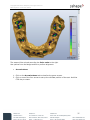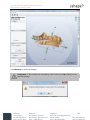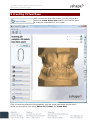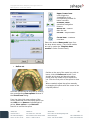
1
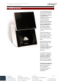
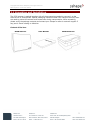
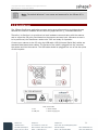
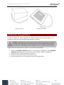
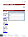
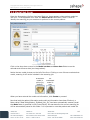
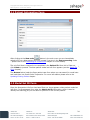
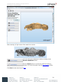
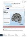
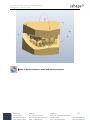
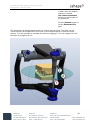
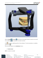
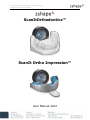
Copyright 2006-2012 3Shape A/S. All rights reserved Ortho System™ 2012 User Manual ScanItOrthodontics™ ScanIt Ortho Impression™ User Manual 2012 Copyright 2006-2012 3Shape A/S. All rights reserved Ortho System™ 2012 User Manual Table of Contents Preface ..................................................................................................................... 3 1 Ortho Control Panel .................................................................................................4 2 R700 Scanner ......................................................................................................... 6 2.1 Unpacking and Installation .................................................................................. 7 2.2 ScanServer .......................................................................................................9 2.3 Scanner Calibration .......................................................................................... 10 2.4 Scanner Transportation .................................................................................... 11 3 Performing a Scanning Job ..................................................................................... 13 3.1 Patient Information Form .................................................................................. 13 3.2 Model Set Form ............................................................................................... 14 3.3 Scanning Dental Models with SIO ....................................................................... 15 3.3.1 Scan Maxilla .............................................................................................. 15 3.3.2 Scan Mandible............................................................................................ 17 3.3.3 Scan Occlusion........................................................................................... 19 3.3.4 Model Alignment ........................................................................................ 20 4 Scanning Dental Impressions with (SIOI) ................................................................. 23 4.1 Patient Information Form .................................................................................. 24 4.2 Model Set ID Form ........................................................................................... 24 4.3 Scanning Job ................................................................................................... 26 4.3.1 Scan Maxilla .............................................................................................. 26 4.3.2 Scan Mandible............................................................................................ 28 4.3.3 Scan Bite .................................................................................................. 30 4.3.4 Cutting...................................................................................................... 31 4.3.5 Model Alignment ........................................................................................ 32 5 Creating Virtual Base ............................................................................................. 41 6 Virtual Articulator .................................................................................................. 45 7 Processing on a Second PC ..................................................................................... 53 7.1 Scan Settings Form .......................................................................................... 54 7.2 Workflow ........................................................................................................ 55 7.3 Post-Processing Mode ....................................................................................... 56 7.4 Switching to Post-Processing Mode from Another Mode ......................................... 56 7.5 Scanning Mode ................................................................................................ 57 8 Updating Existing Orders in SIO and SIOI ................................................................. 57 2 Copyright 2006-2012 3Shape A/S. All rights reserved Ortho System™ 2012 User Manual Preface ScanItOrthodontics™and ScanIt Ortho Impression™ are the applications designed for the fast and reliable 3D scanning of orthodontic models and impressions respectively with the help of the 3Shape R700™ Scanner. The R700™ Scanner represents the next generation of scanning technology, and is optimized for the scanning of plaster casts or impressions at the orthodontic practice or laboratory. This manual will introduce you to the ScanItOrthodontics™ application and R700™ Scanner and will guide you through the main steps of 3D scanning with the help of our software. From herein, it is assumed that the user is familiar with basic concepts related to orthodontics. OS-SIOSIOI-5.4.0.1-EN-A Copyright 2006-2012 3Shape A/S. All rights reserved Ortho System™ 2012 User Manual 1 Ortho Control Panel Ortho Control Panel™ is where you can customize all parameters used in ScanItOrthodontics (SIO), ScanIt Ortho Impression (SIOI), OrthoAnalyzer™ and Appliance Designer™. It is the first thing you should open after the installation (Ortho Control Panel -> System Settings): Similar settings apply to ScanIt Ortho Impression: ScanItOrthodontics (or ScanIt Ortho Impression) is currently installed in folder – If no folder is specified here, please use the Browse button to select the folder where the program was installed. Usually, this will be C:\Program Files\3Shape\SIOrthodontics(or ScanItOrthoImpression)\. Save raw scan data – If checked, the raw scanner output will be saved for each scanning job. This allows old orders to be re-processed without re-scanning. So for example, if you are unhappy with the resolution of models for a given patient, you can change the Reduce file size to value (see below) and then re-process the corresponding order. However, note that these files are quite large (typically 25MB for a single scan). 4 Copyright 2006-2012 3Shape A/S. All rights reserved Ortho System™ 2012 User Manual Note: Saving the raw scan data helps performing a in-depth diagnosis of the scanner and is recommended if you experience issues in the scanning process. Cut and close base (ScanItOrthodontics ONLY) – If checked, a neat horizontal cut will be made near the bottom of each model, and the bottom will then be closed. It results in an air-tight model with a cleaner visual appearance however, this leads to a slightly increased processing time; moreover, this feature is not always desirable (e.g. if you are designing a virtual base for your scanned models). Reduce file size to – The option lets you specify the amount of the file size reduction at a cost of reduced detalization. The lower the value, the lower the resolution of the final model where some details may get smoothed out. Transform maxillary (ScanItOrthodontics ONLY) – When checked, transforms the upper model if only the maxillary model is scanned. Save format: STL: Standard open format. DCM: 3Shape compressed format. Gives smaller files, but not supported by external software. PTS: Only the raw scan points are saved. However, the points will still be processed (temporarily) in order to allow alignment. PTSCyra: Special point cloud format (for very special cases only). VRML: Is an alternative format for saving models. It is primarily used for saving face scan models in 3Shape software. Data folder – The folder specified here is where all scanned models and patient data will be stored. Use the Browse button to select your favorite location. This is also the folder where OrthoAnalyzer will read and store its data. Note that sub-folders will be created automatically for each patient and each scanning job, so you do not have to worry about the Data folder getting too cluttered. 5 Copyright 2006-2012 3Shape A/S. All rights reserved Ortho System™ 2012 User Manual 2 R700 Scanner The introduction of the new advanced 3Shape R700 scanner builds up on 3Shape's scanning expertise and is optimized for scanning of dental gypsum models up to 40% faster and with greater details than 3Shape's previous R640 scanner. The R700 scanner guarantees superior scan results without compromising the ease of use. The R700 allows you also to scan models directly as poured from the impression tray without the need for a base. Easy and quick object fixation followed by a few clicks in the scanning software makes the scanner easy to use and require a minimal amount of training. The patient’s original occlusion is registered using the provided 2cast fixture and can easily be altered onscreen with the help of the virtual articulators. The scanner employs a unique 2-camera and 3axis motion system, which results in unrivaled accuracy in object geometry acquisition. 6 Copyright 2006-2012 3Shape A/S. All rights reserved Ortho System™ 2012 User Manual 2.1 Unpacking and Installation The R700 scanner is packed together with all the accessories needed to connect it to the scan-server PC and operate. Special packaging materials made from transport security foam are used to protect the scanner and accessories during transportation. When unpacking, please verify the package contents and contact your 3shape re-seller’s customer support if any part is found missing or defective. Content of the box: R700 Scanner User Manual Calibration box 7 Copyright 2006-2012 3Shape A/S. All rights reserved Ortho System™ 2012 User Manual The calibration box contains: 1. Power supply 2. USB dongle key (red or blue) 3. Calibration "dot plate" 4. Pontic scan pin 5. Pontic scan pin protection foam 6. Scanning clay 7. USB cable 8. 3 x Scanning plates 9. Calibration "Square" 10. Power cord 11. Waxup fixture 12. Impression fixture 13. 2-Cast fixture The R700 scanner is tested, sold and delivered together with an approved PC. 3Shape does not guarantee the functioning of the R700 if: • third party software is installed on the ScanServer PC; • third party computer peripherals are installed (e.g. USB flash key, WLAN adapters); • the software is installed on a different PC. 8 Copyright 2006-2012 3Shape A/S. All rights reserved Ortho System™ 2012 User Manual Note: The default Windows™ user name and password for the 3Shape PC is "scan". 2.2 ScanServer The 3Shape ScanServer application program works as a software driver to bridge the gap between the scanner hardware and the scanning applications e.g., ScanItOrthodontics. Therefore, its function is to provide a low-level hardware communication with the scanner and to output the 3D point cloud based on the scanner cameras input. Whenever a scan is to be performed, the ScanServer needs to be "ON" and ready for operation. Connect your scanner to the PC using the USB cable. USB (Universal Serial Bus) cables are standard data transmission cables. The flat end of the cable is plugged into the computer, the square end into the scanner. The USB cable should be plugged into one of the rear ports of the computer. 1. Fan 3. USB port Rear of the R700: 2. Power switch 4. Power supply port 9 Copyright 2006-2012 3Shape A/S. All rights reserved Ortho System™ 2012 User Manual Connect the power supply to the scanner power supply port and plug the power supply to the power outlet. Use standard precaution when operating the scanner power supply. Caution! We strongly recommend that both the scanner power supply and scanserver PC power cable are plugged into a UPS unit (rather than directly into the mains outlet) to prevent work losses and damages to the equipment. With the launch of ScanServer, an icon with a flashing green light appears in the system tray. When this green light becomes steady, the ScanServer is ready for operation. Launch the ScanServer application only after having plugged the scanner to the scan-server PC and switching the scanner "ON"; otherwise, the following error message will pop up: "No scanner is connected to the PC by USB. Please check the power and USB cable and try again". 2.3 Scanner Calibration By calibrating the scanner the internal scanner geometry and camera parameters are calculated. It is recommended to calibrate the scanner each time it is moved or at least twice a week. However, if the scanner is placed on a stable table and at a constant temperature, the calibration intervals can be increased. A calibration is always required when a scanner is first unpacked. An indication of a poorly calibrated scanner is a scanned model with a rough surface. When this happens, check if it is a recurrent problem, as it might be attributed to the object not properly placed on the fixture, or the fixture is not firmly fixed to the black interface plate. Try scanning different objects, and in particular objects of different materials. If the problem persists, please contact your 3Shape re-seller’s customer support. No other maintenance besides calibration is required for the scanner. Caution: Beware that the scanner is a precision mechanical device sensitive to temperature and power variations as well as vibrations. The calibration is performed using the ”dot plate” calibration object and the ”square calibration object” supplied with your scanner (see images below). The procedure is simple and nearly completely automatic: 1. Click on the ScanServer icon in the system tray, and the ScanServer window will pop-up. Press Calibrate scanner button on the ScanServer window in the lower right part of the screen. You will be prompted for a password, which is ”docal”. The reason for the password is to keep unauthorized personnel from trying to calibrate the scanner. 2. A new window opens. Follow the detailed instructions in this window, which will guide you through the full calibration process. 10 Copyright 2006-2012 3Shape A/S. All rights reserved Ortho System™ 2012 User Manual Calibration "square" Calibration "dot plate" 2.4 Scanner Transportation In order to protect the scanner against any possible damage during transportation, it is necessary to use the original packaging materials and boxes. Caution: The swing axis of the scanner should be secured each time the scanner is transported using the swing protection foam. If the original packing materials have been lost or damaged, a new packaging set can be ordered from 3Shape. Please follow the steps below to perform a successful transportation: 1. Press the Transport Position button in the ScanServer application. The Transport Position button cannot be pressed when the calibration wizard is displayed. 2. Switch off the PC and disconnect the scanner. 3. Fasten the swing axis using the protection foam. 4. Place the scanner into the original box using the original foam. 11 Copyright 2006-2012 3Shape A/S. All rights reserved Ortho System™ 2012 User Manual The scanner is packed correctly The swing axis foam is packed correctly 12 Copyright 2006-2012 3Shape A/S. All rights reserved Ortho System™ 2012 User Manual 3 Performing a Scanning Job When everything is setup and ready for scanning, you start the application. ScanItOrthodontics is started by double-clicking the ScanItOrthodontics desktop icon or via the Windows™ Start menu: Start -> All Programs -> 3Shape -> 3Shape ScanItOrthodontics. 3.1 Patient Information Form When you open ScanItOrthodontics you are immediately asked to fill out a New patient info form (except if you are in the Postprocessing mode – please refer to the Processing on a Second PC chapter for more details). The only required field to fill out is the Patient ID. Once this is filled out, click Create to proceed. The New patient model set info form appears (see the Model Set Form chapter). The Browse button loads the Open patient case form where you can search for model sets and load them into ScanItOrthodontics. For more information please refer to the Updating Existing Orders chapter. Copyright 2006-2012 3Shape A/S. All rights reserved Ortho System™ 2012 User Manual 3.2 Model Set Form Once the New patient info form has been filled out, there appears a New patient model set info form. In the appeared form enter the Model set ID information, which is used to identify the scanning job you are about to perform for the current patient: Click on the drop-down menus in the Model set date and Scan date fields to use the calendar and choose a date (see image above). Notice the two model pictures on the left of the form. Clicking on one of these unselects that model, meaning it will not be included in the scanning job. A selected model is yellow (by default) An unselected model is gray When you have entered the model set information, click Create to proceed. Now that both the patient information and model set information have been filled out, a folder called ”Data folder/Patient_ID/Model_Set_ID/” has been automatically created (recall that Data folder is specified in the Control Panel). All scan data for the current scanning job will be automatically saved to this folder. It is important to note that patient and model set 14 Copyright 2006-2012 3Shape A/S. All rights reserved Ortho System™ 2012 User Manual information forms should only be filled out from a scanning PC (i.e. not from a PC in the Post-processing mode – please see the Processing on a Second PC chapter for details). You can create a new patient at any time since the Create new order button (image to the left) is available throughout the whole scanning process. 3.3 Scanning Dental Models with SIO Now that all relevant information has been entered, you will be guided through the steps needed to scan all models. Essentially, the only thing you need to ensure is that the models are inserted in the correct way into the scanner: Note: The front teeth should always face the inside of the scanner, and there should be approximately 1cm of blue clay underneath the model, holding it firmly in place. A typical scanning job will consist of three scans: the maxillary model, the mandibular model, and the occlusion model (which consists of the maxillary on top of the mandibular, in correct occlusion, e.g. using 3Shape’s specially designed fixture). After all three scans are complete, you will be asked to help the software in performing the alignment. 3.3.1 Scan Maxilla After you have filled out the New Patient info form and the New patient model set info form, the main ScanItOrthodontics window opens up offering you to insert the maxillary model for scanning. Insert the model correctly and click Next. 15 Copyright 2006-2012 3Shape A/S. All rights reserved Ortho System™ 2012 User Manual 1. Main toolbar 2. Overview toolbar 3. Function panel 4. Session window 5. Visualization toolbar Visualization toolbar contains the following buttons: Item Action View – The view buttons allow you to switch between a number of predefined viewpoints: Front view Rear view Right side view Left side view Top view Bottom view Difference map - shows the difference between the model and the occlusion in color. Difference map for maxillary/mandibulary - shows the difference between the maxillary and mandibular models in color. 16 Copyright 2006-2012 3Shape A/S. All rights reserved Ortho System™ 2012 User Manual 2D cross section - sets 2D cross section of the model. Rotate view – When selected, right-click and drag to rotate the view. Pan view – When selected, right-click and drag to pan the view. Zoom view – When selected, right-click and drag to zoom in and out. Zoom all – Sets the model to the default view, size and position on the screen leaving its current rotation angle intact. 3.3.2 Scan Mandible After the maxillary model has been scanned, the program asks you to insert the mandibular model. Note that the Rescan maxilla button has appeared in the Function panel so you can rescan the maxillary model if necessary. Use the Show maxillary model slider in the upper right corner to set the transparence of the scan. Insert the mandibular model correctly and click Next. 17 Copyright 2006-2012 3Shape A/S. All rights reserved Ortho System™ 2012 User Manual Use the Sculpt maxilla button to correct the scan of the model: Sculpt toolkit The Wax knife option allows you to add or remove surface on the selected area. Click the Add button in the Wax knife settings section to add some material to the scan. The target area circle is marked red. Select the Remove button to delete extra material or click the Smooth button. The target area circle is marked blue and green respectively. Adjust the Radius and Level of the marking circle by pulling the corresponding slide bars. It is possible to use the already customized settings from the list of six variants. Activate the desired mode by clicking at its number in the list. To change the setting for the mode set the parameters in the Wax knife settings section and click the Save button. Mark the Show target area checkbox to display the marking circle. 18 Copyright 2006-2012 3Shape A/S. All rights reserved Ortho System™ 2012 User Manual It is possible to Undo (1)/Redo (2) the last operations. Click the black arrow to observe the history of your actions. Click OK to save the changes. You can use the Difference map to observe the changes you perform in color. Click the black arrow to open the Difference map options. Show bands - Makes it easier to see slices on difference map with the same deviations. Show legend - displays the Color scale. 3.3.3 Scan Occlusion After the mandibular model has been scanned, the application offers you to insert the occlusion model, i.e. both the maxillary and mandibular models together, using the provided 2-cast fixture. Put the models in occlusion (potentially using a wax bite if one is necessary) and close the fixture on the two models as illustrated in the image to the left. Insert the fixture with the models’ front teeth facing the inside of the scanner. After the occlusion scan, press the fixture’s top button to release the models: Note that the Rescan mandible button has appeared in the Function panel so you can rescan the mandibular model if necessary. 19 Copyright 2006-2012 3Shape A/S. All rights reserved Ortho System™ 2012 User Manual Use the Sculpt mandible option if you want to trim your scan (for more information see the Scan Mandible chapter). Insert the occlusion correctly and click Next. 3.3.4 Model Alignment After scanning has been finished, the program displays all three scans and asks you to align the models. There are tree ways to do it: Normal, Advanced and Auto. You can choose either of them by selecting the corresponding radio button (see image below). Normal method The alignment is performed by placing the corresponding points on the models. The hints on how to place the points correctly are illustrated at the top of the Register scan alignment form (see the image below). Click on the maxillary model, somewhere near the front teeth (try to avoid flat areas). Then click on the corresponding area on the occlusion model. Do the same thing for the mandibular model, thus resulting in 4 points. You can change the position of a point by dragging it (click and hold down the mouse). 20 Copyright 2006-2012 3Shape A/S. All rights reserved Ortho System™ 2012 User Manual If you are satisfied with the result, click Apply to perform the alignment. Once the alignment is complete, you can click OK to accept it, or click one of the Reset buttons to try again using different points. You can use the Models visibility form in the upper right corner to show the occlusion model at any time – this can help you evaluate the quality of the alignment, as the occlusion model is of a different color. Note that there is a 2D cross-section tool, as well as the Difference map, in the Visualization toolbar. These tools (particularly the 2D cross-section) can help you evaluate the quality of the alignment. Advanced method If for some reason the Normal alignment method does not produce a satisfactory result, you can click Reset all and switch to the Advanced mode. With this method, you must set 3 points on each model, as illustrated in the image below. The order of operations is: 1. 2. 3. 4. 5. 6. Set 3 points on maxillary model. Set 3 corresponding points on occlusion model. Click Apply. Set 3 points on lower part of occlusion model. Set 3 corresponding points on mandibular model. Click Apply. 21 Copyright 2006-2012 3Shape A/S. All rights reserved Ortho System™ 2012 User Manual The hints on how to place the points correctly are illustrated in the Register scan alignment form (see image below). Auto To avoid the manual alignment and save time, you can use the Auto alignment option. Click Apply and the scans will be adjusted by the program. It is possible to adjust the transparency of the models by dragging the appropriate sliders. To activate the slider mark the checkbox in front of it first. 22 Copyright 2006-2012 3Shape A/S. All rights reserved Ortho System™ 2012 User Manual 4 Scanning Dental Impressions with (SIOI) When everything is setup and ready for scanning, you start the application. ScanIt Ortho Impression is started by double-clicking the ScanIt Ortho Impression desktop icon or via the Windows™ Start menu: Start->All Programs->3Shape->3Shape ScanIt Ortho Impression. Important remarks on dental impression scanning with the R700: Using the ScanIt Ortho Impression application allows you to scan full dental impressions for orthodontic applications. Due to the complexity of the impressions’ geometry, and the use of 3Shape’s unique adaptive scanning method to automatically cover this geometry, the scan of dental impressions is typically slower than for dental casts. Alginate and Silicone impressions can be scanned in the R700 scanner. Most impression materials can be scanned but 3Shape will publish a list of materials, which are known to cause scanning issues and should be avoided. Since the R700 scanner uses optical technology (i.e. laser light source), the impression’s surface must not be too wet/reflective. It is therefore recommended to wipe excess liquid from the alginate impression’s surface using a tissue, or to use a spray on a dry surface in the case of too shiny silicone materials. A spray can also be applied to the material used for the bite registration (wax or silicone). The impression must be scanned in its original tray. Note: To fit into the scanner, the impression tray’s handle must not be more than 4 cm long and 0,7cm thick. The impression handle must preferably be straight so that the impression is not elevated in the scanner. Copyright 2006-2012 3Shape A/S. All rights reserved Ortho System™ 2012 User Manual 4.1 Patient Information Form After clicking at the New order button in the main menu you are immediately asked to fill out a New patient info form (except if you are in the Post-processing mode – please refer to the Processing on a Second PC chapter for more details). The only field that is required to be completed is the Patient ID. Once this is filled out, \ click Create to proceed. The New patient model set info form appears (see the Model Set Form chapter). The Browse button loads the Open patient case form where you can search for model sets and load them into ScanIt Ortho Impression. For more information please refer to the Updating Existing Orders chapter. 4.2 Model Set ID Form Once the New patient info form has been filled out, there appears a New patient model set info form. In the appeared form enter the Model set ID information, which is used to identify the scanning job you are about to perform for the current patient: 24 Copyright 2006-2012 3Shape A/S. All rights reserved Ortho System™ 2012 User Manual Click on the drop-down menus in the Model set date and Scan date fields to use the calendar and choose a date (see the image above). Notice the two model pictures on the left of the form. Clicking on one of these unselects that model, meaning it will not be included in the scanning job. A selected model is yellow (by default) An unselected model is gray Scan bite allows scanning the patient's bite for further model alignment. This option is selected by default. When you have entered the model set information, click Create to proceed. Now that both the patient information and model set information have been filled out, a folder called ”Data folder/Patient_ID/Model_Set_ID/” has been automatically created (recall that Data folder is specified in the Control Panel). All scan data for the current scanning job will be automatically saved to this folder. It is important to note that patient and model set information forms should only be filled out from a scanning PC (i.e. not from a PC in the Post-processing mode – please see the Processing on a Second PC chapter for details). You can create a new patient at any time since the Create new order button (image to the left) is available throughout the whole scanning process. 25 Copyright 2006-2012 3Shape A/S. All rights reserved Ortho System™ 2012 User Manual 4.3 Scanning Job Once all relevant information has been entered, you will be guided through the steps needed to scan all models. Place the impression holder’s handle in the supplied Impression fixture. Note: For impressions, the front teeth should always face the outside of the scanner. If the impression material and/or tray cause the fixture to tip, place approximately 1cm of blue clay underneath the impression to hold it in place. A typical scanning job will consist of three scans: the maxillary model, the mandibular model, and the occlusion model (which consists of the maxillary on top of the mandibular, in correct occlusion, e.g. using 3Shape’s specially designed Waxup fixture). After all three scans are complete, you will be asked to help the software in performing the alignment. 4.3.1 Scan Maxilla After you have filled out the New Patient info form and the New patient model set info form, the main ScanIt Ortho Impression window opens up offering you to insert the maxillary model for scanning. Insert the model correctly and click Next. 26 Copyright 2006-2012 3Shape A/S. All rights reserved Ortho System™ 2012 User Manual 1. Main toolbar 2. Operation buttons 3. Session window 4. Visualization toolbar The Visualization toolbar in ScanIt Ortho Impression contains similar functions as the one in ScanItOrthodontics, except for the two buttons: Model visibility - enables visualization of the necessary 3D model elements. Show law quality areas - highlights the unscanned areas. After selecting the Model visibility button, there appear the visibility slide-bars in the upper right corner of the window: maxillary model, mandibular model and bite model. Select the necessary radio button and drag the slide-bar sideways with the mouse to change the model’s view. After inserting the model into the scanner and clicking Next the scanning process begins. The areas that are being scanned are shown in the Scanning process window: The scanned area is marked as red. You can interrupt the scanning process by clicking the Stop button. After scanning you get a scan of the model on a screen: 27 Copyright 2006-2012 3Shape A/S. All rights reserved Ortho System™ 2012 User Manual You can rescan the maxillary model by clicking the Rescan maxillary button. Select the Show low quality areas button to view if any places on the model are left unscanned. The unscanned area is marked as purple. Click the Sculpt button to trim your scan results. For further information see the Scan Maxilla chapter. Click Next to start scanning the mandibular model. If you do not wish to continue with scanning, click the Finish the process button. 4.3.2 Scan Mandible The scanning process for the mandibular model is similar to the maxillary one. Remove the maxillary impression from the scanner and insert the mandibular one. Click Next to continue. 28 Copyright 2006-2012 3Shape A/S. All rights reserved Ortho System™ 2012 User Manual After scanning you get a scan of the model on a screen: You can rescan the mandibular model by clicking at the Rescan mandibular button. Use the Sculpt option to correct the results of scanning process. For more information see the Scan Maxilla section. Click Next to start scanning the bite. 29 Copyright 2006-2012 3Shape A/S. All rights reserved Ortho System™ 2012 User Manual 4.3.3 Scan Bite If you have selected the scan bite option while filling in the New patient model set info form, you can proceed with the bite scanning. Remove the mandibular impression from the scanner and insert the bite. Click Next to continue. Note: For bite scanning the mandibular side should face the outside (i.e. door) of the scanner. After scanning you get a scan of the bite on a screen. Remove the bite from the scanner and click Next to proceed to the cutting step. You can rescan the bite by clicking at the Rescan bite button. 30 Copyright 2006-2012 3Shape A/S. All rights reserved Ortho System™ 2012 User Manual 4.3.4 Cutting After the bite has been scanned, you can trim your scan to remove the excess material, which is crucial for the successful alignment. Cutting the maxillary scan Place a spline (colored green) to mark the area on a scan that will NOT be cut. Area beyond the spline will be removed. To place a spline, left-click on a scan to set points or drag the mouse while holding down the left mouse button. You can control the process of cutting with the help of the buttons located in the bottom left corner of a window: Select Show points to make the cutting points visible. 31 Copyright 2006-2012 3Shape A/S. All rights reserved Ortho System™ 2012 User Manual Choose Clear to start marking again. Press OK to end the process. Cutting the mandibular scan Perform the same actions as for the mandibular scan to attain a successful cut. Click Next to proceed to alignment. 4.3.5 Model Alignment The cutting process if followed by the model alignment. Step 1: Align your scan to the wax bite Place three points on the bite and on the maxillary/mandibular scan correspondingly. 32 Copyright 2006-2012 3Shape A/S. All rights reserved Ortho System™ 2012 User Manual To redo the points click the Clear button. To end the process of alignment, click the Align button. 33 Copyright 2006-2012 3Shape A/S. All rights reserved Ortho System™ 2012 User Manual Click Next to proceed with alignment. Step 2: Align the models to avoid intersection Move to the Touch section, click the Clear button to proceed with the alignment. The transparent models appear on the screen. Place three points in the corresponding places on both models to ease the alignment. You can drag the points to the desired position by holding the left button of the mouse. 34 Copyright 2006-2012 3Shape A/S. All rights reserved Ortho System™ 2012 User Manual After setting the points click Correct to apply the changes. If you wish to change the placement of the points click Clear. Step 3: Detect and correct the collisions 35 Copyright 2006-2012 3Shape A/S. All rights reserved Ortho System™ 2012 User Manual It is possible to correct the collisions by using the options in the Collisions section: If the model has areas marked with red, click Optimize to align the model. You can observe the problem areas with the help of the Difference map option: 36 Copyright 2006-2012 3Shape A/S. All rights reserved Ortho System™ 2012 User Manual The areas will be colored according the Color scale to the right. Use options from the Nudge section to perform alignment: Arrow buttons 1. Click on the Arrow buttons tab to visualize the green arrows. 2. Click on one of the four arrows to set up the ultimate position of the cast. Hold the CTRL key to rotate. 37 Copyright 2006-2012 3Shape A/S. All rights reserved Ortho System™ 2012 User Manual Transition step – sets up the distance for which the cast moves up or down at one click on the arrow. Rotation step – sets up the degree of rotation of the model. Trans box 1. Click on the Trans box tab to visualize the corresponding bounding box. 2. Drag the purple control points (turn yellow when active) to set up the ultimate position of the cast. 38 Copyright 2006-2012 3Shape A/S. All rights reserved Ortho System™ 2012 User Manual Click Restore to undo the changes. Important: If the models are intersecting, after clicking the OK button you will get the warning: 39 Copyright 2006-2012 3Shape A/S. All rights reserved Ortho System™ 2012 User Manual When the aligning process is complete you can Rescan the bite, Realign models or Finish the Process by clicking at the relevant buttons. 40 Copyright 2006-2012 3Shape A/S. All rights reserved Ortho System™ 2012 User Manual 5 Creating Virtual Base After finishing the alignment process, you can proceed and select the Create Virtual base button in the Function panel to create the virtual base for your model. Click on it and the software will automatically open the Virtual base dialog window which guides you through its main steps: Define Cut, Fit Base and Create Base. Copyright 2006-2012 3Shape A/S. All rights reserved Ortho System™ 2012 User Manual Upper/Lower base icons toggle the visualization of the corresponding models for better overview. Previous /Next operations navigation buttons. Define cut – used to draw the cut. Fit base – adjusts base. Create base - creates a new base. Select the desired Base model type from the drop-down menus. (The virtual models are set up under the Template base models in Ortho Control Panel). Define cut Decide on the part of the model you wish to leave, click the Define cut button if not already at this step and place the spline points over the model curve to define the cut. Click the first point of the spline to close it. Where needed, adjust the spline manually by dragging the points with the cursor to the required position. Incorrect splines can be removed by clicking the corresponding Clear splines buttons in the Virtual base dialog. From the right-click menu options of the cursor positioned over the cutting spline you can Add new or Remove indicated spline points, Clear spline or use Fast edit function to correct the spline . 42 Copyright 2006-2012 3Shape A/S. All rights reserved Ortho System™ 2012 User Manual For Fast edit, left-click on the spline and move the cursor while holding the mouse button down to draw a new part of the spline. Fit base Once maxilla and mandible splines have been placed, click the Next or the Fit base buttons to go to the Fit base step. You can adjust orientation of the base by dragging the violet points and the base size with the green points of the bounding box. Click and hold the mouse button to drag the bounding box to the required position. The following parameters of the base can be modified: Show Virtual Base – toggles visualization of the virtual base. Scale Symmetrically – sets whether the bounding box is scaled symmetrically when dragging by the green points. Decimate base to specifies the decimation amount of the base triangles (see image below). 43 Copyright 2006-2012 3Shape A/S. All rights reserved Ortho System™ 2012 User Manual Curvature - sets the amount of curvedness for the base model along the sides (see image below). Dist. between bases - Specifies the distance between the maxillary and the mandibular bases. Offset - specifies the distance between the initial shapes of the base and the baseless model. IMPORTANT: if the cutting spline is not contained in the blue base model at the Fit Base stage, the combined 3D model cannot be generated. Decimation by 5%, 50% and 80% respectively. Curvature sets the amount of curvedness for the base model along the sides. Create base Once adjustments to the bounding box at the Fit base step are complete, click the Next or Create base button to create the virtual base. Click OK to close the Virtual base dialog window. Your models now appear to have virtual bases. 44 Copyright 2006-2012 3Shape A/S. All rights reserved Ortho System™ 2012 User Manual Base offset 0mm and 2mm respectively The image below shows the virtual base using the included Arch Max and Arch Man bases STL models: It is possible to create new model set on this step. Click the New model set button (see the image to the left). Once you click the icon the New patient model set info form appears (for more information see the sections Model Set Form and Model Set ID Form). The new model set is saved under the active patient and is available in the Open patient case form. 6 Virtual Articulator The Virtual Articulator feature can be activated with the Articulator button in the Visualization toolbar during the design process. 45 Copyright 2006-2012 3Shape A/S. All rights reserved Ortho System™ 2012 User Manual Step 1: Modify the alignment of the jaws The Modify button in the Virtual Articulation window and moving the control points with the cursor for a better fit (see the images below). Occlusal change - The indicated value of displacement in the occlusion direction is relative to the original static occlusal and shown in millimeters. It can be set directly by clicking the value and keying in the number directly or selecting it with the buttons next to the value. Use the buttons in the Virtual articulation window to undo your changes to the static occlusion (1) or update the static occlusion with the current alignment of the jaws, when you are satisfied with the results (2). Click the Optimize occlusion button to align jaws automatically. The red control point allows to rotate the jaw. The blue control point allows you to move the jaw up and down: 46 Copyright 2006-2012 3Shape A/S. All rights reserved Ortho System™ 2012 User Manual Step 2: Setup articulator model and adjust placement 47 Copyright 2006-2012 3Shape A/S. All rights reserved Ortho System™ 2012 User Manual Click the button on the Virtual articulator window to start the setup. Select the type of the articulator from the drop-down menu clicking the arrow button . It is possible to place the model in the articulator according to the Occlusion plane, selected from the popup menu. Set up the desired plan first in the Additional plane views section. Bennett L, Bennett R, Cond. incl. L, Cond. incl. R are articulator model parameters, they can be set by clicking the appropriate editboxes and entering their parameters manually or selecting them with the buttons next to the values. The Auto placement (1) button allows you to customize the default placement method and perform auto placement of the model. Click it to open the Auto placement options window: You will need to click the Browse button and select your placement file to use. The Set as default button saves you current auto placement method to use as the default one for future orders. The Perform placement button initiates the auto placements process with the chosen options. Analyze scans is selected for the models without adaptor plates. You can load predefined planes created in e.g .OrthoAnalyzer, such as the occlusion plane as default position in the articulator by checking the User Guide plane box and selecting the plane from the drop-down list. Mark the Use guide plane to activate the drop-down menu of the predefined planes, used for the placement. Articulator specific option 48 Copyright 2006-2012 3Shape A/S. All rights reserved Ortho System™ 2012 User Manual is used when the adaptor plates are included. Use custom placement allows you set the path of the placement. Click the Browse button to set the Placement file path. The placement can be adjusted manually by moving the blue plane. The plane can be moved up/down and rotated with the cursor by the indicated points to find the correct position. It is also possible to translate the plane by dragging it. You can change the tilt of the plane by dragging its rim: 49 Copyright 2006-2012 3Shape A/S. All rights reserved Ortho System™ 2012 User Manual 1. Moves the articulator up and down 2. Rotates the articulator 3. Change the angle of the articulator position Step 3: Use articulator to evaluate and adapt design Click the the settings tab. on the Virtual articulator window to open To set Occlusion, Laterotrusion and Pro-/retrusion you can: Edit the parameters in the appropriate edit boxes in the Virtual articulation window. Move the jaws by holding the left button on the mouse ( the red control point appears and the parameters are updated automatically). Click the locked button to change it to the unlocked to free the movement of the required plane. Place the cursor over the articulator/model and drag it while keeping the mouse button pressed: 50 Copyright 2006-2012 3Shape A/S. All rights reserved Ortho System™ 2012 User Manual With the Upper / Lower when resetting Click jaw button you can select the jaw you want to move with the articulator to the static occlusion. to lock the modelling position of the articulator. To set the articulator in modelling position click . There are three options in the Articulate function: Contact mode : OFF: no contact is recorded 51 Copyright 2006-2012 3Shape A/S. All rights reserved Ortho System™ 2012 User Manual ON: contacts are recorded but the articulator can be manipulated freely like a physical articulator AUTO SHUT: will always maintain a contact between the two jaws; so in effect the articulator cannot be opened completely. Collide designs - indicates in color the collisions of the jaws. The Occlusal compass button allows to color the areas of collision according to the specific articulator movement using the legend below (2): When the occlusal compass is disabled, contact colors areas are shown in blue (1): The legend of the compass Record contacts - if checked, enables the Adapt design section. Indicate the Min distance and Adaption radius by setting the parameters in the appropriate edit boxes. The operation can be undone with the Undo button. Step 4: Simulate articulation 52 Copyright 2006-2012 3Shape A/S. All rights reserved Ortho System™ 2012 User Manual It is possible to imitate the articulation motions by clicking the articulation. Click . Click the to pause the process or button to start the to stop it. To repeat the process click button to customize the motion sequence: 1. List of sequences 2. Edit buttons 3. Operation buttons 4. Motion view section The List of sequences can be customized with the Operation buttons. Add new sequence, Move up/down the list or Delete from the list. 7 Processing on a Second PC Scanning a model consists of two independent parts: 53 Copyright 2006-2012 3Shape A/S. All rights reserved Ortho System™ 2012 User Manual 1. The actual scanning, during which raw scan data is captured. 2. Post-processing, during which the raw scan data is transformed into a surface. ScanItOrthodontics allows these parts to be split onto two separate PCs, in order to save time. Such a configuration can be set up in the Scan settings form. 7.1 Scan Settings Form The Scan Settings form is accessed through the File menu in the top left corner: The form contains two tabs: Scanners and Options. The Scanners tab should essentially never be changed, except in rare cases. Fill in your scanner's name/location in the Add scanner to list field (click Add to save) or select the required scanner from the Current scanner drop-down menu. Click Remove to remove the current scanner from the list. The content of the Options tab is described below: Mode – This is where you can set up processing on a second PC. The following modes are available. Scanning and post-processing: The current PC will perform both the scanning and processing (this is the default configuration). Scanning: The current PC will perform only the scanning part. In this mode, you must also specify the following: Name of the second PC – This is the computer name of the second PC. It can be found on the second PC under the System Properties (Start -> Control Panel -> System -> Computer Name -> Full computer name). 54 Copyright 2006-2012 3Shape A/S. All rights reserved Ortho System™ 2012 User Manual Note: All references to network or company name should be omitted (for example, if the computer name in the System Properties is “PC101.3Shape.local”, then you should only enter “PC101” here. Shared folder – Here you specify a shared folder on your local network, or on the second PC, which will be used to exchange files between the two PCs. Note: If this folder is on the second PC, as opposed to the network, then it must be specified in the form “\\Second PC’s name\…”, and not “C:\....”. The shared folder must have write privileges (i.e. it must not be "Read only"). Post-processing: The current PC will perform only the post-processing part. Scanning optimized for - presents 2 options: Speed and Universal. Speed allows for a quicker scan scanning process. Universal is he scanning process including additional subscans and post-processing steps. Note that ScanItOrthodontics is set to Universal by default. Caution: Your configuration of the setting “Scanning Optimized for” (Speed and Universal) has a direct impact on the performance of the scanning process, as well as the hardware requirements. Thus, the Universal setting requires significantly more virtual memory and RAM during operation when compared to the Speed settings. Please contact your local 3Shape service provider in case of problems with this feature. Noise reduction mode - allows to reduce visual noise, i.e. points that are not aligned with the captured surface. 7.2 Workflow When splitting the scanning and post-processing steps on separate PCs, it is very important to do things in the correct order; otherwise your work will not be saved! The correct order of operations is as follows: 1. Start ScanItOrthodontics on the processing PC (see the Post-Processing Mode chapter). 2. Start ScanItOrthodontics on the scanning PC and fill out the patient and model set information forms. Start scanning, as usual (see the Performing a Scanning Job chapter). 3. The alignment is performed on the processing PC. Performing and evaluating the alignment are the only things you should do on the processing PC. Everything else must be done from the scanning PC: creating new orders, re-scanning, etc. Note: All files are saved on the processing PC, in the location specified in the Control Panel. Nothing is saved on the scanning PC. 55 Copyright 2006-2012 3Shape A/S. All rights reserved Ortho System™ 2012 User Manual 7.3 Post-Processing Mode When ScanItOrthodontics is started in the Post-processing mode, there will be no patient information to fill out. Instead, you will immediately see the following: At this point, the program is waiting for the scanning PC to send information. You should now start ScanItOrthodontics on the scanning PC and enter all patient and model set information. As soon as this is done, the patient ID will be displayed in the program’s title bar on both PCs. Therefore on the processing PC, you will see the following: 7.4 Switching to Post-Processing Mode from Another Mode If your version of ScanItOrthodontics is currently in a different mode, and you would like to switch to the Post-processing mode, please do the following: 1. Run ScanItOrthodontics. You will immediately see the patient info form (since you are not yet in the Post-processing mode). Click Cancel on this form, thus closing it. 2. Go to the File menu and choose Scan settings. In the Options tab, change the mode to Post-processing. 3. Click the Create new order button in the top left corner. Your PC is now ready to receive data from the scanning PC. 56 Copyright 2006-2012 3Shape A/S. All rights reserved Ortho System™ 2012 User Manual 7.5 Scanning Mode In the Scanning mode, ScanItOrthodontics works almost exactly as in the Scan and postprocessing mode described in the Performing a Scanning Job chapter. Essentially, the only difference is that it will not perform the alignment – this is done on the processing PC. Note also that all surface models (i.e. STL or DCM) will appear only on the processing PC. Note: The scanning PC does not know anything about what the processing PC is doing or has done. Therefore, do not create a new order from the scanning PC if there is a pending order on the processing PC, on which you have not yet performed alignment. Only once the alignment is complete should you define a new order on the scanning PC (this does not apply if the pending order does not require alignment). 8 Updating Existing Orders in SIO and SIOI ScanItOrthodontics allows you to load orders you have previously scanned. This can be useful in the following situations: 1. If you want to (re-)scan the occlusion of the patient once the impressions have been scanned. In this case, you will scan a new occlusion bite, i.e. add data to the existing scanned data -and then perform a new alignment according to this new scanned bite, so here you can modify an existing scanned data set without creating any new data. 2. After you have completed a scanning job, you find some problem that you had not noticed while performing the scanning job. For example, you might think the alignment is a bit off and would like to redo it. 3. You might feel that the file sizes of the models are too large, and would like to produce lighter (more “decimated”) models. Note: In cases 2 and 3 you will only use the existing scanned data. To load an existing order, click the Load order button (image to the left). Alternatively, you can use the Browse button on the New patient info form (see the Patient Information Form chapter for details). 1. Click the Search button in the top right corner to see all cases which are currently in your Data folder (recall that this folder is defined in the Control Panel). 2. Click the little black triangle next to a patient: this will display all model set IDs (i.e. scanning jobs) for this patient. 3. Double-click the scanning job you want to load. 57 Copyright 2006-2012 3Shape A/S. All rights reserved Ortho System™ 2012 User Manual Adding the occlusion scan To add an occlusion scan to the existing scanned Model Set (i.e. new scan data for occlusion only), please perform the following steps: Step 1: Select the patient in the list (i.e. not the model Set). Carefully note the ID of that model set. Step 2: Double-click on the patient name, or right-click and choose Open Patient. Step 3: The Model Set ID Form is displayed. Enter the ID of the model set you want to modify (VERY IMPORTANT to modify the existing set), select the Occlusion scan option and click Create. Step 4: The conformation dialogue appears. Click Yes to confirm you want to overwrite the existing Model Set: Step 5: Click on Next to import the existing Maxillary scan and click Yes when asked whether to load the existing data: 58 Copyright 2006-2012 3Shape A/S. All rights reserved Ortho System™ 2012 User Manual Step 6: Wait for the post-processing of the maxillary scanned data to be completed until the model appears on screen. Step 7: Click on Next to proceed to the Mandibular side and load existing scan (click on Yes) and wait until the mandibular post-processing has been completed and the surfaced model is displayed on screen. Step 8: Insert the occlusion bite and complete with the scanning and alignment processes described in section Scan Bite. Redoing the alignment Load all surface models (i.e. STL or DCM files) to redo the alignment. Go to the File menu and select Load all surface models. This will make the models appear on the screen. You can now click the Realign models button and redo the alignment. Note: It is only possible to load surface models if all three models exist: maxillary, mandibular, and occlusion. This is because this functionality is only intended for performing re-alignment. Re-processing the existing raw scan data As mentioned previously, you can obtain new surface models without re-scanning, applying alternative file reduction presets in the Ortho Control Panel. To do this, click Next as if you were starting a scan. You will then see the message illustrated on the image to the right. If you choose Yes, the scan will be skipped and postprocessing will begin immediately. If you choose No, a new scan will be started. When post-processing of a model is complete, click Next as you would normally do when scanning. Note: This functionality is only possible if Save raw scan data checkbox was selected in the Control Panel at the time of the original scan. Hint: The existing surface models will be automatically replaced by the newly processed models. So if you want to retain the originals, you will need to manually back up these files before proceeding. 59 Copyright 2006-2012 3Shape A/S. All rights reserved Ortho System™ 2012 User Manual 60