1
US005383140A
United States Patent [19]
[11]
[45]
Nanno et al.
[54] POWER SUPPLY CONTROL SYSTEM FOR A
PORTABLE COMPUTER
643196
7/1962 Italy .............................. .. Dl3/et 2.1.
OTHER PUBLICATIONS
title are in the Japanese language), pp. 5-211 through
5-223 and unnumbered ?nal page, published by Toshiba
Related US. Application Data
Continuation of Ser. No. 862,056, Apr. 2, 1992, aban
doned, which is a division of Ser. No. 541,978, Jun. 22,
1990, abandoned.
[30]
Jan. 17, 1995
“User’s Manual, Four-bit Microcontroller and Periph
eral Memory, TLCS-47E/47/470/470A” (portions of
[21] Appl. No.: 111,400
[22] Filed:
Aug. 25, 1993
[60]
5,383,140
FOREIGN PATENT DOCUMENTS
[75] Inventors: Nobuyuki Nanno; Kazuo Akashi;
Hiromi Seimiya, all of Tokyo, Japan
[7 3] Assignee: Kabushiki Kaisha Toshiba,
Kanagawa, Japan
Patent Number:
Date of Patent:
Foreign Application Priority Data
Corporation, dated 1991.
Toshiba T1600 Portable Personal Computer User’s
Manual, pp. 2-1 through 2-11, undated.
Toshiba T5100 Portable Peronal Computer Reference
Manual, 4 pages, undated.
Toshiba T5200 Portable Personal Computer Reference
Manual, 6 pages, undated.
Primary Examiner-Tan V. Mai
Jun. 23, 1989 [JP]
Japan ................................ .. 1-162228
Attorney, Agent, or Firm-Finnegan, Henderson,
Jun. 23, 1989 [JP]
Jun. 23, 1989 [JP]
Jun. 23, 1989 [JP]
Japan
Japan
Japan
Farabow, Garrett & Dunner
l-162229
l-162231
1-162234
[57]
ABSTRACT
A power supply control system for a portable computer
[51]
Int. Cl.6 .............................................. .. G06F 1/00
[52]
US. Cl. ............................... .. 364/708.1; 364/707;
[58]
Field of Search ................ .. 364/708.1; ZOO/43.01,
[56]
ZOO/43.18, 43.22, 318, 322, 327; Dl3/ 171, 162
References Cited
ZOO/43.01
U.S. PATENT DOCUMENTS
D. 310,818
4,571,456
9/1990 Zaretsky et a1. ................ .. D13/125
2/1986 Paulsen et a1. ................ .. 364/708 X
having a central processing unit (CPU), and operable in
response to power supplied from a rechargeable battery
or an alternating current (AC) adapter. The control
system includes a charge unit for charging the recharge
able battery; current detectors for detecting power
status; and a power control microprocessor for control
ling the charge unit independently of the CPU in re
sponse to a detected power status.
3 Claims, 8 Drawing Sheets
US. Patent
A1
Jan. 17, 1995
Sheet 3 of 8
@IQE
5,383,140
@
{NORMAL 8*TTERY s\
YES
><
NOAZ
‘ A3'\ AC—A\I;APTER
ED FLICKERED LED
‘Magus >
(L2.L3) Tug»: ON
\
BNORMAL
INPUT
-
was
04/‘
N0
\
A5
RED L I GHT LED
(L33 Tl RN ON
M5~
\
{ NORMA J CHARGE
N
0
YES
A7
A8
\
v
\ORANGE
1. mm LE
(L21 TU N ON
A12
A
9
>5
DISPLAY
\
COVER
W'D
N0
A13
POWER
\
swi'rcn
NO
A14
\!
NORMAL @
z
7 N0
ES
CHARGE-UN I T
@
A10
YES
'
N0
|
COUNTER
COUNTS
' +1‘
V
A1 1\
‘5——-—-——*
1
CHARGE-UNIT
A15
?
\
-\
CHARGE-UNIT
VOLTAGE DOWN
YES
up
v
\ f
VOLTAGE
Q—_<vALus
N0
IS N‘? 0F coum‘sa
YES
TO POWER-ON ROUTINE
FIG. 3
UP
US. Patent
Jan. 17, 1995
@aomzmed l i MmBOmwmo
Ameam;zo
wg?l a
um/ao.9zwmh5uc2z:m<ou //:.s5m9_oz0
2
.¢
1
m;
Sheet 4 of 8
5,383,140
GFQE
@
OPm mkaO Pmz_DOM
wuom
US. Patent
Jan. 17, 1995
5,383,140
Sheet 5 of 8
B11
\
/NORMAL CHARGEABLE
YESW
B12
NO
\
DISCHARGABLH
ABNORMAL
CURRENT?
YES
NO
\
ARRANGED ‘vol/FAQs OF
HARM-UN T
814
\
STATE
OF
LOW
_
‘
‘
NO
YES
B15
VOLTAGE
LEVEL
-‘
W
YES
ISPLAY
YES
NO
‘
NO
B16
RED FL I CKERED
D (-21 ON
POWER
0 1
B24
SWITCH
7
NO
YES
\
t
COUNTER
UP
B18
' +
COUNTED
'
B25
NORMAL
VALUE
OF
NO
YES
R‘ED I LIGHT LE
B20
RESET SWITCH
N9.
.
TRANSMI‘I' SYSTEM
POWER OF REQUEST
TO MAIN CPU
db
FIG. 4(b)
‘
US. Patent
Jan. 17, 1995
Sheet 6 of 8
5,383,140
US. Patent
Jan. 17, 1995
Sheet 7 of 8
5,383,140
US. Patent
Jan. 17, 1995
L1
LED
LAYOUT
Sheet 8 of 8
L2
L3
)
)
1
L)
B
G)
o
o
POWER
BATT.
Dc-m
DISK
CAPS
/SPEED
_
UGHT
GREEN
ORANGE
RED
COLOR
/RED
/RED
(*1)
/GREEN
(*2) (*3)
RED
5,383,140
o
o
NUM SCROLL
KANA
GREEN GREEG GREEN
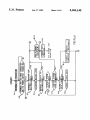
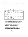
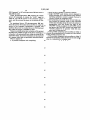
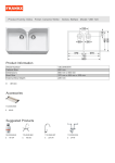
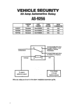
#1 AS CPU ACTUATED AT HIGH SPEED CLOCK '10Mhz', GREEN LIGHT.
AS CPU ACTUATED AT LOW SPEED CLOCK 'BMhz", RED UGHT.
#2 AS BATTERY BEING CHARGED RAPIDLY, ORANGE UGHT.
AS STATUS OF LOW BATTERY, RED FUCKERING UGHT.
AS BATTERY HAS BEEN COMPLETED, GREEN UGHT.
#3 AS AG-ADAPTER IS USED OR CHARGING, RED UGHT.
AS INPUT VOLTAGE OF AO-ADAPTER OR OUTPUT VOLTAGE
AT POWER-ON TIME IS ABNORMAL, RED FLICKERING UGHT.
1
5,383,140
2
and the current ?owing from current detectors, com
parison means for comparing a detected voltage and
current with a reference voltage and current, and
means, coupled to a plurality of display elements, for
displaying the status of voltage and current in response
POWER SUPPLY CONTROL SYSTEM FOR A
PORTABLE COMPUTER
This application is a continuation of application Ser.
No. 07/862,056 ?led Apr. 2, 1992, now abandoned
to the comparison means, whereby the display element
which in turn is a divisional application of Ser. No.
shows a low battery state when the detected voltage is
07/54l,978 ?led Jun. 22, 1990, now abandoned.
below the reference voltage and a voltage abnormality
state when a voltage abnormality is present.
Other objects, features, and advantages of the present
invention will become apparent from the following
detailed description. It should be understood, however,
that the detailed description and speci?c examples
while indicating preferred embodiments of the inven
tion, are given by way of illustration only, since various
changes and modi?cations within the spirit and scope of
BACKGROUND OF THE INVENTION
This invention relates generally to computers and,
more speci?cally, the power supply of a portable bat
tery operated computer. The invention includes both a
system and the methods for controlling efficiently the
power supply of such a portable computer.
15
As is known, recently computers have been devel
oped which are convenient to carry. In conventional
computers of these types, there are two primary meth
ods for supplying the power. In one case, the power is
the invention will become apparent to those skilled in
the art from this detailed description.
supplied by an alternating current (AC) adapter. In the 20
BRIEF DESCRIPTION OF THE DRAWINGS
Other objects and features of the present invention
will be apparent from the following description taken in
other case, the power is supplied by internal batteries.
In these two methods mentioned above, the central
processing unit, hereafter called “CPU”, must always
connection with the accompanying drawings, in which:
verify the status of the external power supply and the
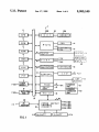
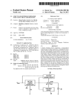
FIG. 1 is a schematic block diagram illustrating a
charge level of the internal batteries. However, in con 25 power supply control system with a power control
ventional methods and systems of these types, a single
circuit for use in a computer system, according to one
CPU also must control the voltages of the external
embodiment of this invention;
power supply and internal batteries, and this creates a
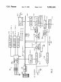
FIG. 2 is a detailed diagram of the power control
burden for one CPU. The presently known systems and
circuit of FIG. 1;
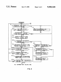
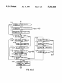
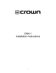
methods for power supply control using one CPU are 30 FIG. 3, 4(a) and (b) are ?owcharts illustrating control
not efficient. Also, the known systems do not include
sequences associated with the power control circuit of
any means for indicating to an operator the voltage or
power supply status, such as whether or not the power
FIG. 1;
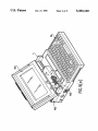
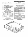
FIG. 5(a) is a perspective top view of a computer
system according to an embodiment of the present in
is off.
SUMMARY OF THE INVENTION
Accordingly, an object of the invention is to effi
ciently control a chargeable power supply and current
?owing from an AC adapter to internal batteries con
stantly.
35
vention;
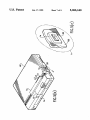
FIGS. 5(b) and 5(0) are other perspective view of the
computer system of FIG. 5(a); and
FIG. 6 is a diagram illustrating how the operating
states of the computer system are displayed in the LEDs
40 used in conjunction with the invention.
A further object of the invention is to indicate the
status of a power supply for a portable computer.
Still another object of the invention is to display the
status of the power supply of a portable computer to the
DETAILED DESCRIPTION OF THE
PREFERRED EMBODIMENTS
FIG. 1 is a schematic block diagram illustrating a
computer’s operator, such as whether or not the power 45 power supply control system with a power control
is off.
microprocessor for use in a computer system according
In accordance with one aspect of the present inven
to one embodiment of this invention. As illustrated,
tion, the foregoing objects are achieved by providing a
computer system 1 includes various computer compo
power supply control system for a computer having a
nents, as follows.
central processing unit (CPU) and operable in response 50 A CPU 11 operates computer system 1 with pro
to power from a rechargeable battery or an alternating
grams stored in a ROM 12 and RAM 13. ROM 12 stores
current (AC) adapter The computer includes a charge
a basic input or output system program, and RAM 13
circuit for controlling a power from the AC adapter to
stores application programs and data for use by an oper
the rechargeable battery, and a power control ‘micro
ator. A direct memory access controller (DMAC) 14
processor independent of the CPU for controlling the 55 controls and sends data directly between RAM 13 and
charge circuit, and a detector for supplying status sig
an input/output apparatus, for example, a hard disk
nals representing a plurality of conditions associated
drive (HDD) 20A and a ?oppy disk drive (FDD) 32,
with the AC adapter to the microprocessor, wherein
etc., apart from CPU 11.
the battery or the charge circuit, and the power control
A programmable interrupt controller (PIC) 15, a
microprocessor includes a circuit for generating control 60 programmable interval timer (PIT) 16 and a timer mod
signals to control the charge circuit in response to the
ule 17 having a real-time clock with a backup voltage
status signal.
(hereafter called “VBK”) of +‘5VDC are provided. An
In accordance with another aspect of the present
expanded RAM 18, using particular card slots, provides
invention, a power supply control system for indicating
VBK. A backup RAM 19 having display data therein
the status of voltage and current in a computer system 65 stores the contents of a program counter for a current
includes:
ly-running program, various registers and a memory
means for monitoring the status of the voltage from
and I/O statuses, so that it can restart an interrupted job
an AC adapter and at least one rechargeable battery,
when repowered.
3
5,383,140
A hard disk pack 20, which ?ts particular card slots,
4
A back-light controller 308 supplies a power to LCD
includes 2.5 inch hard disk drive (HDD) 20A and a hard
37 in response to a set of variable registers to control the
disk controller (HDC) 20B. A ?oppy disk controller
(FDC) 20F controls access to ?oppy disk drive (FDD)
32 connected thereto. A printer controller (PRT
intensity of back-light of LCD 37. An LED driver 309
CONT) 21 controls access to a printer 34 connected
thereto by a cable.
controls an LED L1 for indicating the ON/OFF state
of power switch 301 and the actuating speed of CPU 11
(as shown FIG. 5(a) in more detail), an LED L2 for
indicating the capacity state of the battery (as shown
A universal asynchronous receiver transmitter
(UART) 22 is a serial input/output interface, provided
FIG. 5(a) in more detail) and an LED L3 for indicating
with a voltage VPH (+ l2VDC) and a voltage VMH
FIG. 5(a) in more detail).
(+9VDC). A keyboard controller (KBC) 23 controls
Each LED displays L1, L2 and L3 each may display
three different colors (e.g., red, green, and orange as
shown in FIG. 6 in more detail). For example, when the
access to a keyboard 36 connected thereto. A display
whether AC adapter 29 (of FIG. 1) is present (as shown
controller (DISP-CONT) 24 controls display of data on
an LCD 37. A video random access memory (VRAM)
green light of LED L1 is on, CPU 11 is actuated at a
25 is a refresh memory to store data to be displayed on
high speed clock frequency of lOMHz. When the red
LCD 37 or CRT display 38, and is provided with VBK.
A kanji-ROM 26 is accessible by kanji character codes,
and stores kanji character patterns.
light of LED L1 is on, CPU 11 is actuated at a low
speed clock frequency of 8 MHz. When the orange light
of LED L2 is on, batteries M-BATT 31a and S-BATI‘
31b are charged rapidly. When the red light of LED L2
A power supply interface (PS-IF) 28 controls a
power supply control circuit 30 and is connected to 20 is ?ickering, M-BA'IT 31a is in a low battery state.
When the green light of LED L2 is on, charging of
CPU 11 via a system bus 10 (to be shown in FIG. 2 in
M-BATT is completed. When the red light of LED L3
more detail). An AC adapter 29 converts an AC voltage
is on, AC adapter 29 (of FIG. 1) is in use or charging.
(+120 V) to a DC voltage (+12 VDC) and is plugged
When the red light of LED L3 is ?ickering, an abnor
into computer system 1 via a DC-in-12V pack. A main
battery (M-BAT'I‘) 31a and a sub battery (S-BATT) 31b
each includes a rechargeable battery (i.e., a nickel-cad
minum battery) to provide 7-8VDC, and may be a
removable pack.
An external ?oppy disk drive (FDD) 33 may be con
nected to FDC 20F by a cable. An RS-232C interface
unit 35 is connectable to a serial input/output interface
UART 22 by a cable, and LCD 37 is connected to
display controller 24. LCD 37 is provided with a volt
age VLD (—22VDC). An expanded connector unit 40
is connected to a system bus 10 and is connectable to
expanded units (not shown) by a cable. Thus, there are
mality is present in the input voltage of AC adapter 29,
or in the output voltage at the power-on time, or in the
self test of the power supply control circuit. A digital
to-analog (D/A) converter 310 converts a digital output
signal from PC-microprocessor 306 to an analog charge
control signal and sends the charge control signal to
charge unit 311. Charge unit 311, which has a 256 bit
DC-DC converter, charges M-BATT 31a in accor
dance with the charge control signal from D/A con
verter 310.
Current detector 312 detects a direct current to both
M-BATT and DC-DC converter 315, 319, and a cur
rent detector 314 detects a direct current to DC-DC
converter 315 alone. DC-DC converter 315 converts a
several alternatives to choose.
FIG. 2 shows a detailed diagram of the power supply
DC voltage (+ l2VDC) from AC adapter 29 or M
control circuit of FIG. 1. In FIG. 2, power supply con 40 BA'IT 31a to a power supply voltage of, for example,
trol circuit 30 has a built-in 4-bit single-chip power
control microprocessor (PC-microprocessor) 306,
which may be a Toshiba module TMP47C440AF.
Power control microprocessor 306 is constantly pro
+5VDC, +12VDC, —9VDC and —22VDC, to be
supplied to computer system 1.
An analog-to-digital (A/D) converter 316 converts
analog input voltages, which are associated with de
vided a power from M-BATT 31a. PC-microprocessor 45 tected current of the current detectors 312 and 314, an
306 includes a CPU, a RAM for storing data, and a
output voltage of M-BA'I'I‘ 31a, the power supply volt
ROM for storing a control program, for example, a
ages and the input voltage of the AC adapter, etc., to a
program for calculating the remaining capacity of M
digital voltage for PC-microprocessor 306. A/D con
BA'IT 31a, i.e., a low battery state, and for including a
verter 316 may have an 8-channel analog input terminal,
low battery table, which is used to detect low battery 50 so as to equally divide the input analog voltages into 255
states with a detected voltage and charging current.
sections. A serial I/O interface 317 communicates com
PC-microprocessor 306 controls power to the computer
mands sent between PC-microprocessor 306 and CPU
components of computer system 1 in accordance with a
11. A charge unit 318 charges S-BATT 31b and a
current state from a charge unit 311 to M-BATT 31a
DC-DC converter 319. DC-DC converter 319 converts
and a DC-DC converter 315, which current state is 55 a voltage from charge unit 318 and S-BATT 31b to
detected by current detectors 312 and 314, and an ON/
VBK to be supplied to expanded RAM 18, backup
OFF state of power-switch 301, a reset switch 302, a
RAM 19 and VRAM 25 (of FIG. 1).
display switch 303, and a mode switch 304. A parallel
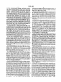
FIGS. 3, 4(a) and 4(b) illustrate a ?owchart of a con
I/O interface 305 is connected to power-switch 301 and
trol sequence performed by PC-microprocessor 306 (of
reset switch 302 for initializing the computer compo 60 FIG. 2), which will be described in detail below.
nents of computer system 1. Display switch 303 supplies
FIG. 5(a) is a perspective view of computer system 1
a power to LCD 37, and mode switch 304 sets the mode
looking from the front thereof when a display cover 401
to actuate the expanded unit of computer system 1.
of computer system 1 is open. FIG. 5(b) is a perspective
Parallel I/O interface 305 holds the ON/OFF states of
view of computer system looking from the rear thereof,
switches 301-304 and sends a value representing the 65 when display cover 401 is closed, As shown in an en
ON/OFF states of these switches to PC-microproces
larged area A of FIG. 5(b), the edges of a push-button
sor 306 via an internal bus 307 or to DC-DC converter
315 and 319 directly.
switch 301 on a side surface 405 of computer body 402
is surrounded by a protect wall la to prevent the opera
5
5,383,140
tor from unintentionally pushing push-button switch
301 while carrying computer system 1, but allow the
operator to intentionally push push~button switch 301
anytime. As shown in FIGS. 5(a) and 5(b), LED dis
plays L1, L2, and L3, etc., are disposed in an edge por
tion adjoining surfaces 1c and 1d of a rectangular block
1b and exposed regardless of whether display cover 401
is open or closed. Therefore, the operator can easily
identify the operating states of the components of com
puter system 1, even when display cover 401 is closed.
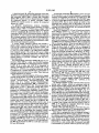
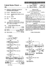
The ?owcharts of FIGS. 3, 4(a), and 4(b) describe a
process whereby PC-microprocessor 306 (FIG. 2) con
trols the power supply. PC-microprocessor 306 in
power supply control circuit 30 (of FIG. 1) detects the
ON/OFF state of power switch 301 at all times. When
power-switch 301 is off, PC-microprocessor 306 exe
cutes the power-off routine shown in FIG. 3.
As shown in FIG. 3, when power-switch 301 is on,
the ON state of power switch 301 is held in parallel I/O
6
LEDs having multiple colors, the operational state of
the computer system is indicated in detail even when
display cover 401 is being closed.
If in step A6 the detected charged current does not
fall outside the predetermined range, it is determined in
step A8 whether the voltage of charge unit 311 at the
point C in FIG. 2 is within a predetermined range be
tween 5VDC and 10.5VDC. If it is not within the pre
determined range, the process returns to step A2. If it is
within the predetermined range, the process advances
to step A9.
In step A9, it is determined whether the current of
charge-unit 311 is higher than 680mA, for example. If it
is not higher in step A9, charge-unit 311 performs one
step up in step All. A voltage between 3.0 VDC and
11.0 VDC from charge unit 311 is divided by an integer
256 (called “one step”) and is added to the voltage
charging M-BATT 31a, in accordance with a control
interface 305 and a corresponding state signal is sent to 20 signal from PC-microprocessor 306 through D/A con
verter 310. If it is higher in step A9, charge-unit 311
PC-microprocessor 301. PC-microprocessor 301 ac
performs a one step down. In step A10 the voltage
knowledges the ON state of power-switch 306 in step
charging M-BATT 31a is reduced by the one step in
A13. In steps A14 and A15, the ON state of power
accordance with a control signal from PC-microproces
switch 306 is acknowledged. The time of switching-on
power-switch 306 by the operator is detected, and then 25 sor 306 through D/A converter 310.
When steps 10 or 11 are completed, in step A12 it is
a counter CTR (not shown) increments one value (+ l),
determined whether display cover 401 is open or closed
and process steps of A1 through A15 are repeated until
in accordance with a switch signal representing the
CTR counts to a predetermined value.
ON/OFF state of display switch 303, which signal is
In step A1, it is determined whether the M-BATT’s
voltage exceeds lOVDC. A signal representing M 30 transferred to parallel I/O interface 305. To detect the
ON/OFF state of switch 303, a line connecting switch
BATT's voltage value at point C in FIG. 2 is sent to
303 to parallel I/O interface 305 is set in advance at a
PC-microprocessor 306 through A/D converter 316. If
signal high level “1”. When display cover 401 is closed,
the determination in step A1 is NO, PC-microprocessor
switch 303 is activated to ground the line, thus changing
sends a signal to activate a red light in LED L2 to
?icker. LED driver 309 sends the signal through paral 35 the line’s logical level from “1” to “0”. If display cover
401 is closed in step A12, the process advances to step
lel I/O interface 305 in step A2, and the process returns
A1. If display cover 401 is open in step A12, the process
advances to step A13.
If the determination in step A1 is YES, it is deter
The power-off-routine from steps A1 to A13 is re
mined in step A3 whether AC adapter 29 is in use. The
voltage value transferred to PC-microprocessor 306 40 peated until the operator activates power switch 301. In
step A13, it is determined whether power switch 301 is
through A/D converter 316 is anywhere between
being turned on. Step A13 may be performed for exam
0.4VDC and IOVDC. If the determination in step A3 is
ple, for 0.4 sec. If it is, CTR counts up to a predeter
NO, the process advances to step A12.
If the determination in step A3 is YES, it is deter
mined value N, and a power-on routine B (shown in
mined in step A4 whether the voltage value supplied 45 FIGS. 4(a) and 4(b)) is performed.
from AC adapter 29 is within a predetermined range
As shown in FIGS. 4(a) and 4(b), the power-on rou
between llVDC and 16VDC. If it is outside the prede
tine commences in step B1. In step B1, PC-microproces
termined range, the process jumps to step A2. If it is
sor 306 sends a control signal to converter controllers
within the predetermined range, the process advances
326 and 328 through parallel I/O interface 305. Con
to step A5, where PC-microprocessor 306 sends a signal
verter controller 326 and 328 control DC-DC converter
to LED driver 309 through parallel I/O interface 305 to
315, 319, respectively, in accordance with the control
to step A1.
activate a red light in LED L3.
In step A6, it is determined whether a charge current
signal, turn on switches 322 and 324 respectively at 0
VDC. Then, the power is supplied to the components of
supplied to M-BATT 31a from charge unit 311 is within
computer system 1.
a predetermined range between 680 mA and 340 mA, 55
In step B2, it is determined whether expanded con
for example, by detecting a current at point C (of FIG.
nector unit is connected and its power switch is turned
2) by current detector 312, which detected current is
on in accordance with a switch signal representing the
transferred to PC-microprocessor 306 throkh A/D
ON/OFF state of mode switch 304, which signal is
converter 316. If the detected charged current is within
provided to parallel I/O interface 305. If the determina
the predetermined range then, in step A7, PC-micro
tion in step B2 is NO, step B2 is repeated. If it is deter
processor 306 sends a control signal to LED driver 309
mined in step B2 that the state of mode switch 304 is
through parallel I/O interface 305 to activate an orange
ON, then it is determined in step B3 whether DC-DC
light in LED L2 to ?ash when the detected charge
converter 315 supplies predetermined voltages of, for
current is within the predetermined range or to activate
example, +5VDC, +12VDC, ——9VDC, and --22VDC
a green light in LED L2 to ?ash at other times repre 65 to the computer’s components, which voltages are sent
senting an adequate charge capacity of M-BATT 31a,
i.e., the time PC-microprocessor 306 detects the charg
ing capacity “-Av” of M-BATT 31a. By driving
to PC-microprocessor 306 through A/D converter 316.
If the determination in step B3 is NO, then as in step
B26, PC-microprocessor 306 sends a signal to LED
7
5,383,140
driver 309 through parallel I/O interface 305 to activate
LED L3 to ?icker red light.
If the determination in step B3 is YES, then as in step
B4, PC-microprocessor 306 outputs a system reset sig1
nal to a system reset controller 330 through parallel I/O
interface 305, and system reset controller 330 in turn
sends the system reset signal to CPU 11. CPU 11 sets up
the computer’s components in response to the system
reset signal.
8
If the determination in step B14 is NO, the process
skips to step B17.
If YES, in step B14, as in step B15, PC-microproces
sor 306 determines whether the voltage from M-BATT
31a to DC-DC converter 315 is below the changed low
battery value. If the determination in step B15 is NO,
LED L2 is actuated to ?icker red light in response to an
output control signal from PC-microprocessor 306.
Then as in step B17, it is determined whether AC
In step B5 as in step B3, it is determined whether 10 adapter 29 is in use. If the determination in step B17 is
DC-DC converter 315 supplies predetermined voltages
to the computer components. If the determination in
step B5 is NO, the process skips to step B26. If the
determination in step B5 is YES, it is determined as in
Step B6 whether CPU 11 has sent a command to PC
microprocessor 306 through PS-IF 28 (of FIG. 1) and
serial I/O interface 317 (of FIG. 2).
NO, the process skips to step B20. If YES in step B17,
as in step B18, it is determined whether the voltage from
AC adapter 29 is 100 VDC or 0 VDC. If the determina
tion in step B18 is NO, the process advances to step B26.
If it is YES in step B18, as in step B19, LED L3 is
activated to ?icker red light in accordance with an
output control signal from PC-microprocessor 306.
If the determination in step B6 is YES, it is deter
In step B20, it is determined whether the ON/OFF
mined as in step B7 whether the command is a “System
state of reset switch 302 is detected, which is transferred
Power Off Comman ”. If the determination in step B7 20 through parallel I/O interface 305. If the determination
is YES, the process skips to step B27 where a system
in step B20 is NO, as in step B22, it is determined
power-off process is performed, which is described in
whether the ON/OFF state of display switch 303 is
detail hereafter. If NO in step B7, PC-microprocessor
306 determines as in step B8 whether the command is a
“back light ON/OFF request.” If the determination in
step B8 is YES, PC-microprocessor 306 sends a “turn
off signal” to back-light controller 308 through parallel
I/O interface 305, and back-light controller 308 turns
off the back-light in response as in step B9, and then the
process advances to B11. Ifthe determination in step B8
is NO, it is determined as in step B10 whether AC
adapter 29 is in use. If it is in use, a red light or red
?ickering light in LED L3 is activated in accordance
with an output control signal from PC-microprocessor
306 as in step B10. Also, PC-microprocessor 306 sends
a low battery state signal to CPU 11 through 810 inter
detected, i.e., whether display cover 401 is open. If YES
in step B22, the process returns to step B3. If NO in step
B22, as in step B23, PC-microprocessor 306 determines
whether the ON/OFF state of power switch 301 is
detected. If a signal transferred through parallel I/O
interface 306 is at a logical level “1”, the process returns
to step B3. If the signal is at a logical level “0”, as in step
B24, PC-microprocessor 301 con?rms the ON state of
the power switch and CTR increments by one (+1). In
step B25, it is determined whether CTR has counted up
to a predetermined value M. If NO in step B25, the
process returns to step B3.
In step B15 or step B20 or B25, if the determination is
YES, the process advances to step B21 and then step
face 317. When a POPUP menu on the display 37 is
B27, wherein PC-microprocessor 306 sends the “Sys
called, the amount of power remaining in M-BATT 31a
tem Power Off Request” to computer system 1, through
is displayed as one of seven-levels.
serial I/O interface 317 and PS-IF 28. In response to the
system power off request signal, CPU 11 sends an
“ACK” to PC-microprocessor 306.
from charge-unit 311 (detected by current detector 312)
When PC-microprocessor 306 does not receive the
and a value representing the current from M-BATT 31a
“ACK” signal, it determines that abnormalities (e.g., a
to DC-DC converter 315 (detected by current detector 45 program overturn) are present in computer system 1,
314) are transferred, i.e., the current value detected by
and performs power off sequence protect HDD 20.
current detector 314 subtracted from the current value
When it receives the “ACK” signal, it waits the “Sys
detected by current detector 312 is within a predeter
tem Power Off Request” from CPU 11 for above a
If the determination in step B6 is NO, it is determined
in step B11 whether a value representing the current
mined range between +255 mAi 10%, for example. If
the determination in step B11 is NO, it is determined as
in step B12 whether the current value from M-BATT
31a is abnormal for the system, i.e., M-BATT 31a may
not be charged up. If YES in step B12, as in step B26,
LED L2 is system activated to ?icker red light. If NO
in step B12, as in step B13, charge-unit 311 performs the
same steps as in steps A8-A11.
If the determination in step B11 is YES, as in step
B14, it is determined whether the state and the manner
minute (above ?ve minutes in lower battery state).
When PC-microprocessor receives the “System
Power Off Request” from CPU 11, it returns the
“ACK” signal to CPU 11. The CPU 11 interrupts the
program currently running and saves the contents of
RAM 13, RAM 18, the I/O statuses, the contents of the
registers, etc. into backup RAM 19 having a memory
capacity of, for example, 16K bytes. If FDD 32 or
HDD 20A is accessed, the save operation is also per
formed after an access end is reached (Resume Func
for calculating the amount of the remaining power of
tion).
the remaining capacity of M-BATT 31a is low. Detec 60 If PC-microprocessor 306 waits for one minute (or
tion of the low battery state and a method of calculating
?ve minutes) but still does not receive the “System
an amount of remaining power is explained in detail in
Power Off Comman ” from CPU 11, it sends a “Time
a copending US. patent application Ser. No. 07,134,370
of the same assignee. PC-microprocessor 306 changes a
low battery voltage value when the low battery state is
detected, in accordance with the current and voltage
Out Power Off Request” to CPU 11.
When CPU 11 receives the “Time Out Power Off
Request,” it returns the “ACK” signal to PC-micro
processor 306 and performs the save operation as much
as possible until the power is turned off. When the save
operation is completed, CPU 11 sends a “System Power
from M-BATT 31a, so as to ensure accurate detection
of the low battery state.
9
5,383,140
Off Comman ” to PC-microprocessor 306 and enters a
10
a body having a plurality of exterior surfaces,
a single ON/OFF push button switch disposed to
project through one of said exterior body surfaces
and being operable to control a supply of power to
halt (HLT) mode.
When PC-microprocessor 306 receives the system
power off command, it returns the “ACK” signal to
CPU 11, cuts off the power to the computer compo
circuitry within the computer body;
a wall projecting outwardly from the one body sur
face beyond the outmost extent of the ON/OFF
nents, and the process advances to the power-off rou
tine.
switch and extending along the one body surface in
As mentioned above, PC-microprocessor 306 per
juxtaposition with and around the edge of the
forms the power off routine shown in FIG. 3, when the
ON/OFF switch, to enclose the ON/OFF switch
power to the computer components is stopped, and 10
and protect the ON/OFF switch from being inad
performs the power on routine shown in FIG. 4(a) and
vertently
pushed by an operator while the com
4(b) when the power is supplied to them.
puter unit is being moved.
Numerous modi?cations and variations of the present
2. The portable computer unit according to claim 1,
invention are possible in light of the above teachings. It 15 wherein the projecting wall is located at a side surface
is therefor to be understood that, within the scope of the
of the portable computer unit.
appended claims, the present invention can be practiced
3. The portable computer unit according to claim 2,
in a manner other than as speci?cally described herein.
wherein the projecting wall is located at the side surface
What is claimed is:
close to a leg portion of a display unit.
.
1. A portable computer unit comprising:
*
25
30
35
45
50
55
65
*
*
*
4K