1
FUEL/AIR DATA COMPUTER
(ADC 2000)
P/NS:
962830A-X-S-4
962830A-1-S-4
962830A-2-S-4
962830A-3-S-4
INSTALLATION MANUAL
REV M
Shadin Avionics
6831 Oxford Street
St. Louis Park, MN 55426
USA
Sales: (800) 328-0584
Customer Service: (800) 388-2849
www.shadin.com
P/N: IM2830-AXS4
IM2830-AXS4
IM2830-AXS4M.DOC, DIR. 962830A-X-S-4
Shadin Avionics
Sec: VII
INSTALLATION MANUAL
FUEL/AIR DATA COMPUTER
P/N 962830A-X-S-4, 962830A-1-S-4, 962830A-2-S-4, 962830A-3-S-4
Rev: M
Page: i of vi
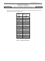
PAGE CONTROL CHART
SECTION
NO.
DESCRIPTION
PAGE
REVISION LOG
1.0
2.0
OVERVIEW
1-1
1.1
1.2
1.3
1.4
1.5
1-1
1-1
1-2
1-3
1-3
The Manual
Product Information
System Configuration
Fuel Totalizer Configuration
F/ADC2000, Argus Moving Map Configuration
FUEL AND AIR DATA SYSTEM SPECIFICATIONS
2-1
2.1
2.2
2-1
2-1
2.2
2-2
2-3
2-4
2-5
2-5
2-5
2-5
2-6
2.6
2-7
2-8
2-8
2-8
2-8
2-8
2-9
2-10
2-11
2-12
2-13
2-14
2-14
2-14
2-14
2-15
2-15
2-15
2-16
2-16
2.3
2.4
2.5
2.6
2.7
2.8
2.9
Input Data Range
Output Data Range
Table 1 – Calibrated Airspeed Tolerance
Table 2 – Pressure Altitude Tolerance
Table 3 – Vertical Speed Tolerance
Table 4 – MACH Tolerance
Dimensions
Power Requirements
Output Data
2.5.1 Serial Output Data Parameters
2.5.2 ARINC 429 (GAMA) Output Labels
Table 5 – ARINC Label Configuration
2.5.3 ARINC 429 Labels Associated with Switch Settings
2.5.4 Start-Up Temperature and Times for Output Data Valid
Limitations
2.6.1 Warm-up Time
2.6.2 Supplemental Equipment
2.6.3 Static/Pitot Source Error Correction (SSEC/PSEC)
2.6.4 SSEC/PSEC Listing
2.6.4 SSEC/PSEC Listing (Continued)
2.6.4 SSEC/PSEC Listing (Continued)
2.6.4 SSEC/PSEC Listing (Continued)
Part Numbering Scheme
Electrical Interface Specifications
2.8.1 Heading Interface
2.8.2 Fuel Flow Interfaces
2.8.2.1 Digital Fuel Flow
2.8.2.2 Sine Wave Fuel Flow
2.8.2.3 DC Voltage Fuel Flow
2.8.3 Baro Interface
Statistical Specifications
2.9.1 Mean Time Between Failures
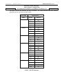
3.0
CERTIFICATION
3-1
4.0
PLACING AN ORDER
4-1
IM2830-AXS4
IM2830-AXS4M.DOC, DIR. 962830A-X-S-4
Shadin Avionics
Sec: VII
INSTALLATION MANUAL
FUEL/AIR DATA COMPUTER
P/N 962830A-X-S-4, 962830A-1-S-4, 962830A-2-S-4, 962830A-3-S-4
Rev: M
SECTION
NO.
5.0
DESCRIPTION
PAGE
INSTALLATION PROCEDURE
5-1
5.1
5.2
5.3
5.4
5.5
5.6
5.7
5.8
5.9
5.10
5-1
5-1
5-1
5-2
5-3
5-4
5-5
5-6
5-6
5-6
General
F/ADC Location Selection
Mounting the F/ADC
Mounting the OAT Probe
Connection to the Fuel Flow Sensor
Connection to the Heading Source
Connection to the Pitot and Static Lines
Connection to the Navigation Management System
Connection to the Altimeter Baro Pot
Post Installation Checkout
6.0
OPERATING INSTRUCTIONS
6-1
7.0
INITIALIZATION
7-1
8.0
MAJOR COMPONENTS OF THE SYSTEM
8-1
Page: ii of vi
IM2830-AXS4
IM2830-AXS4M.DOC, DIR. 962830A-X-S-4
Shadin Avionics
Sec: VII
INSTALLATION MANUAL
FUEL/AIR DATA COMPUTER
P/N 962830A-X-S-4, 962830A-1-S-4, 962830A-2-S-4, 962830A-3-S-4
Rev: M
SECTION
NO.
9.0
10.0
DESCRIPTION
PAGE
CONFIGURING THE AIR DATA
9-1
9.1
9.2
9-1
9-2
9-3
9-3
9-4
9-5
9-6
9-7
9-8
9-8
9-9
9-10
9-11
9-12
9-13
9-14
9-14
Configuring with ‘ADSETUP User Manual’
Configuring Manually
Loopback Procedure 1 for S/W Version 93.02.67
Stage 0 Loopback Configuration
Stage 1 Loopback Configuration
Stage 1 Loopback Configuration
Stage 2 Loopback Configuration
Stage 3 Loopback Configuration
Loopback Procedure 2 for S/W Version 93.04.02 and above
Stage 0 Loopback Configuration
Stage 1 Loopback Configuration
Stage 1 Loopback Configuration
Stage 2 Loopback Configuration
Stage 3 Loopback Configuration
Stage 4 Loopback Configuration
Select No Delay
Special Options
SETTING THE K-FACTOR
Setting the K Factor
Table 6 - Analog K-Factor Settings
Table 7 - Digital K-Factor Settings (Matrix 0)
Table 7 - Digital K-Factor Settings (Matrix 0) – Continued
Table 7 - Digital K-Factor Settings (Matrix 0) – Continued
Table 8 - Alternate Digital-K Factor Setting Table 3 (Matrix 1)
10-1
10-1
10-2
10-3
10-4
10-5
10-6
Page: iii of vi
IM2830-AXS4
IM2830-AXS4M.DOC, DIR. 962830A-X-S-4
Shadin Avionics
Sec: VII
INSTALLATION MANUAL
FUEL/AIR DATA COMPUTER
Rev: M
11.0
P/N 962830A-X-S-4, 962830A-1-S-4, 962830A-2-S-4, 962830A-3-S-4
Page: iv of vi
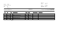
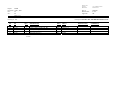
INSTALLATION DRAWINGS AND INSTALL KIT PARTS LISTS
Drawing No.
Description/Part Number
DATE
REV
4028-005
Installation, OAT Probe Assembly Kit
P/N 681201-1
02/14/05
C
N/A
Parts List, OAT Probe Assembly Kit
P/N 681201-1
04/06/07
H
4028-395
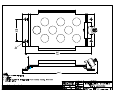
Installation, Mounting Tray, ADC 2000
08/01/05
C
4028-857
Installation, ADC2000 MS Conn, No FF, Quick Start
P/N 962830A-X-S-4
03/07/05
B
4028-871
Installation, ADC2000 MS Conn, Digital FF, Quick Start
P/N 962830A-1-S-4
03/07/05
A
4028-872
Installation, ADC2000 MS Conn, Sine FF, Quick Start
P/N 962830A-2-S-4
03/07/05
A
4028-873
Installation, ADC2000 MS Conn, DC FF, Quick Start
P/N 962830A-3-S-4
03/07/05
A
4028-874
Installation Wiring, ADC 2000 to
COMM/PWR/BARO/OAT/Heading, Quick Start
03/19/01
B
4028-875
Installation Wiring, ADC 2000 Quick Start Digital, Sine,
and DC Fuel Flow
05/02/05
C
4028-A44
Installation Wiring, ADC2000, MS Conn, QS to Altimeter
Baro Pot
03/19/01
C
4028-A62
Installation Wiring, Loop Back Harness for
F/ADC 200, 2000 MS Connector
09/28/98
–
4028-A80
Label, ADC 200/2000 Access Cover
P/N 712801
02/14/05
A
4070-005
Installation, Serial to Argus 5000/7000 Converter
P/N 937000-03
02/14/05
B
N/A
Parts List, Install Kit, ADC2000, MS Conn/No OAT
P/N IK9630A-1
04/09/07
H
4028-876
Installation Wiring, F/ADC 2000 w/ Analog FF to Beech
King Air Indicators
03/26/98
A
IM2830-AXS4
IM2830-AXS4M.DOC, DIR. 962830A-X-S-4
Shadin Avionics
Sec: VII
INSTALLATION MANUAL
FUEL/AIR DATA COMPUTER
Rev: M
11.0
P/N 962830A-X-S-4, 962830A-1-S-4, 962830A-2-S-4, 962830A-3-S-4
Page: v of vi
INSTALLATION DRAWINGS AND INSTALL KIT PARTS LISTS (cont.)
AIRCRAFT SPECIFIC
4028-A29
Installation Wiring, F/ADC-200, 2000 or DigiData with
DC FF Piper Cheyenne PA31T
01/17/05
C
4028-A31
Installation Wiring, F/ADC 2000, MS Conn, Sine FF to
Mitsubishi MU-300 and Model 400 Beechjet
08/14/98
–
4028-A32
Installation Wiring, F/ADC 2000 to Mitsubishi MS Conn
Sine FF, MU-2 w/Foxboro PC-620 System
07/19/00
A
4028-A33
Installation Wiring, F/ADC 2000, MS Conn, with DC FF to
Cessna Citation 500, 501, 550, S550, 551, 552
08/14/98
–
4028-A34
Installation Wiring, F/ADC 2000 MS Conn with DC FF to
Cessna Citation 525 Jet
08/14/98
–
4028-A35
Installation Wiring, F/ADC 2000, MS Conn with Digital
FF to Bombardier LearJet 24, 25D
08/14/98
–
4028-A36
Installation Wiring, F/ADC 2000 MS Conn with Sine FF to
Rockwell Commander 690 and 695
08/14/98
–
4028-A37
Installation Wiring, F/ADC 2000, MS Conn with DC FF to
Raytheon BeechJet 400A Aircraft
08/14/98
–
4028-A38
Installation Wiring, F/ADC 2000, MS Conn, with DC FF to
Westwind 1124 Models
08/14/98
–
4028-A39
Installation Wiring, F/ADC 2000, MS Conn to Fairchild
SA226 Series Aircraft
08/14/98
–
4028-A40
Installation Wiring, F/ADC 2000, MS Conn to
Aerospatiale AS365N2 Dauphin
08/14/98
–
4028-A41
Installation Wiring, F/ADC 2000, MS Conn to
Aerospatiale AS332 Super Puma
08/14/98
–
4028-A42
Installation Wiring, F/ADC 2000, MS Conn Shadin FF
Indicators to Bendix/King Nav. Receiver
03/19/01
A
4028-A43
Installation Wiring, F/ADC 2000, MS Conn and Shadin
Converter to Eventide Argus
03/19/01
B
4028-B98
Installation Wiring, F/ADC2000, MS Conn Shadin FF
Indicators to Garmin 430/530
04/29/11
D
IM2830-AXS4
IM2830-AXS4M.DOC, DIR. 962830A-X-S-4
INSTALLATION MANUAL
Shadin Avionics
Sec: VII
FUEL/AIR DATA COMPUTER
P/N 962830A-X-S-4, 962830A-1-S-4, 962830A-2-S-4, 962830A-3-S-4
Rev: M
Page: vi of vi
REVISION LOG
REV
–
A
DATE
10/17/97
8/20/98
APP’D
B
12/08/98
KCL
C
1/31/00
EDJ
D
9/08/00
EDJ
E
10/06/00
BVM
F
11/01/00
KCL
G
9/26/02
EDJ
H
9/26/03
EDJ
J
K
L
M
3/7/05
9/22/05
4/25/07
5/17/11
ZK
ZK
ZK
ZK
KCL
KCL
CHANGE
Baseline release
Format change, update Limitations section, include aircraft specific wiring drawings.
Update section 2.3, 9.9, 9.10, 9.11, and Table 1. Update DWG No. 4070-005, replace DWG No.
4028-A30 with 4028-A62, and include DWG No. 4028-A29 and 4028-A80.
Added Bendix B & Garmin, Format G, Loran output to page 9-7. Changed page iv due to change
on page 11-16. Added one more Ragen Indicator / Transmitter to 4028-A29 installation wiring
drawing.
Page iii changed by OAT kit and 4028-874 upgrade. Page iv changed by 4028-A43 correction
and 4028-A98 new dwg. Page 1-1 and 1-3 changed by Garmin 430/530. Page 2-1 changed by
OAT tolerance, IVS change of 10,000 fpm, and lowering PITOT and IAS low end speed to 18
knots per BELL requirements. Page 2-2, 2-3, & 2-4 changed by Labels 234 & 235 and Mk VI &
VIII inclusion. Pages 2-9 & 2-10 changed by Raytheon Hawker HS-125-3A page move.. Page 52 & 8-1 changed by OAT kit. Page 5-4 changed by adding Sandel hdg source. Pages 9-1, 9-2 &
9-3 changed by software revision. Pages 9-7 changed to correct Bendix descriptions. Altimeter
Types heading added to page 9-5, 9-8. Page 9-11 moved to 9-16. Pages 9-11 to 9-15 added for
Procedure 3. Page 5-5 changed to add one more AN816 fitting. Page 2-6 changed by adding
TSO statement under Section 2.6.
Correct units for IVS Accuracy to 40 ft/min and range to +/- 10,000 ft/Min
Added sections 2.8 and 2.9. Updated sections 5.1, 5.7 and 9.2. Moved section 9.0 to
page iii. Moved page 9-16 to 9-21. Updated Dwg # 4028-A44.
Baseline release Cfg C with software versions 93.04.02 and 71.73.03. Added P/N
681201 OAT probe installation and parts list to page iv drawing list. Updated Page 2-4
and 2-5 ARINC Table. Corrected page 10-3 Table 2. Replaced pages 9-11 to 9-16
Changed Alternate Digital K-Factor table to include 48000 PPG. Removed 681201A-1
install drawing and parts list. Updated Section 2.5.2 & 2.6.1. Deleted Loopback
Procedure 1 and renumbered Procedure 2 & 3 to 1 & 2. Updated Section 9.0 & 9.2.
Changed Company Name. Updated pages 9-5, 9-10, and Section 11.0.
Updated 2.2, IK9630A-1, 4028-395, 4028-875, 4028-B98 sections 3-1, 5-1, 8-1 and page 10-5.
Changed Company Name. Updated IK9630A-1 and 681201-1 parts list.
Incorporated 4028-B98 Rev D, 4028-875 RevC, 4028-395 Rev C, 681201-1 Rev H, IK9630A-1
Rev H, changed Sec. 2.2, removed 2.5.2 an 2.5.3 and added 2.5.3
IM2830-AXS4M.DOC
IM2830-AXS4
DIRECTORY: 962830A-X-S-4
Shadin Avionics
INSTALLATION MANUAL
FUEL/AIR DATA COMPUTER
P/N 962830A-X-S-4, 962830A-1-S-4, 962830A-2-S-4, 962830A-3-S-4
Rev: M
1.0
OVERVIEW
1.1
The Manual
Page: 1-1
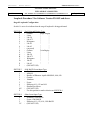
This manual is designed to facilitate the installation of the Shadin Fuel/AIR DATA Computer
(ADC 2000).
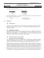
1.2
Product Information
The Shadin ADC 2000 system is designed to provide a combined source of fuel and Air Data.
Listed below are the navigational systems that the ADC 2000 has been designed to be compatible
with.
Receives Serial Data from:
Magellan
Skynav 5000
ARNAV
STAR 5000
FMS 7000
R5000
Trimble
2000/2000A
2100/3000
3100/2101
Bendix King
KLN90
KLN90A
KLN90B
KLN89/89B
KLN900
Garmin
150, 155, 155XL, 165
230, 230XL
300, 300XL
430, 530
BFGoodrich
Pronav LNS 6000
IIMorrow
611, 612, 618
NMS 2001
800, 820, 360
GX50, 55, 60
Transmits Serial Data to:
ARNAV
Magellan
Bendix/King
Trimble
Garmin
Transmits ARINC Data to:
Bendix King
ASINC
Airshow
EFIS 40/50
Global
GNSX
GNS-Xls
Trimble
TNL8100
Note: To find out which particular receiver
models have AIR DATA receive capability,
contact the manufacturers.
Honeywell
SPZ-5000
Data Nav III
IIMorrow
2101
Universal
UNS-1M
IM2830-AXS4M.DOC
IM2830-AXS4
DIRECTORY: 962830A-X-S-4
Shadin Avionics
INSTALLATION MANUAL
FUEL/AIR DATA COMPUTER
P/N 962830A-X-S-4, 962830A-1-S-4, 962830A-2-S-4, 962830A-3-S-4
Rev: M
1.3
Page: 1-2
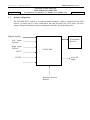
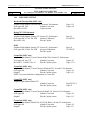
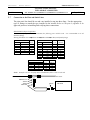
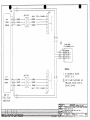
System Configuration
The Fuel/AIR DATA system is a remote mounted computer, which is connected to the GPS
receiver via serial data. It is also connected to the pitot and static line, OAT probe, fuel flow
sensors, altimeter barometric pressure potentiometers and the aircraft heading source.
Magnetic heading
Navigational
Receiver
Left engine
fuel flow
Right engine
fuel flow
F/ADC 2000
PITOT
STATIC
Arinc 429
output
Barometric Pressure
Interface
IM2830-AXS4M.DOC
IM2830-AXS4
DIRECTORY: 962830A-X-S-4
Shadin Avionics
INSTALLATION MANUAL
FUEL/AIR DATA COMPUTER
P/N 962830A-X-S-4, 962830A-1-S-4, 962830A-2-S-4, 962830A-3-S-4
Rev: M
1.4
Page: 1-3
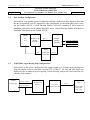
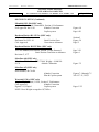
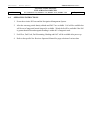
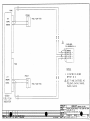
Fuel Totalizer Configuration
Shown below is an optional system configuration utilizing a Shadin Fuel Flow Indicator. Note that
the only navigational receivers supported in this configuration are the Bendix/King KLN series
and the Garmin 430/530. Consult Drawing Number 4028-A42 contained in this manual for
installation information for the Bendix/King KLN series. Consult Drawing Number 4028-B98 for
installation information for the Garmin 430/530.
Garmin
Bendix/King
430,
530
KLN90, A, B
KLN89
KLN900
Shadin
DigiFlo
MiniFlo
MicroFlo
RS-232
L. Fuel Flow Transmitter
R. Fuel Flow Transmitter
or
Shadin
RS-232
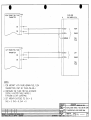
1.5
F/ADC200
F/ADC2000
RS-232
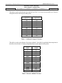
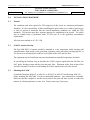
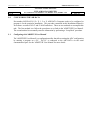
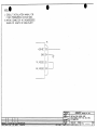
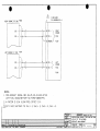
F/ADC2000, Argus Moving Map Configurations.
Shown below is the system configuration that supports output to a Eventide Argus moving map
using the Shadin serial to serial data converter P/N 937000-03. The fuel and AIR DATA are
displayed on the Eventide-Argus moving map. Consult Drawing numbers 4070-005 and 4028-A43
contained in this manual.
Shadin
RS-232 or RS422
F/ADC2000
RS-232 or RS422
Shadin
Navigational
Receiver
RS-232
Converter
P/N 937000-03
Eventide
Argus
M oving M ap
P/N 5000
P/N 7000
IM2830-AXS4M.DOC
IM2830-AXS4
DIRECTORY: 962830A-X-S-4
Shadin Avionics
INSTALLATION MANUAL
FUEL/AIR DATA COMPUTER
P/N 962830A-X-S-4, 962830A-1-S-4, 962830A-2-S-4, 962830A-3-S-4
Rev: M
2.0
FUEL AND AIR DATA SYSTEM SPECIFICATIONS
2.1
Input Data Range
Pitot
Static
OAT
Heading
Fuel Flow
K Factor
2.2
18 to 350 kt.
-1000 to 55,000 ft.
-60°C to +60°C
0 - 360°
1 to 450 GPH Range Selected
500 to 130000 PPG Continuous
Output Data Range
Parameter
IAS
P.ALT
OAT
TRUE HEADING
MAGNETIC HEADING
IVS
TAS
MACH
WIND SPEED
WIND DIRECTION
FUEL FLOW
Accuracy*
Table 1
Table 2
±1.5°C per TSO
±2°
±1°
Table 3
Table 1
Table 4
±5 kts.
±10°
±2%
* Listed accuracy’s are at 25°C and after warm-up is complete.
Range
20 to 350 kts.
–1000 to 50000 ft
–60°C to +60°C
0 - 360 degrees
0 - 360 degrees
± 10,000 ft./min.
20 - 600 kts
.2 - .95
5 - 360 kts
0 - 360 degrees
1 - 450 GPH
Page: 2-1
IM2830-AXS4M.DOC
IM2830-AXS4
DIRECTORY: 962830A-X-S-4
Shadin Avionics
INSTALLATION MANUAL
FUEL/AIR DATA COMPUTER
Rev: M
P/N 962830A-X-S-4, 962830A-1-S-4, 962830A-2-S-4, 962830A-3-S-4
Page: 2-2
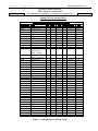
This table is used as the tolerance for both IAS and TAS. For values between table rows, linearly
interpolate between the adjacent table points.
AIRSPEED
KNOTS
TOLERANCE
± KNOTS
50
80
100
120
150
200
250
300
350
400
450
5.0
3.0
2.0
2.0
2.0
2.0
2.4
2.8
3.2
3.6
4.0
Table 1 - Calibrated Airspeed Tolerance
This table is used as the tolerance for pressure altitude. Note that for an altitude between points in
the tables, the tolerance is linearly interpolated between the adjacent table points.
ALTITUDE
FEET
TOLERANCE
± FEET
0
1000
2000
3000
4000
5000
8000
11000
14000
17000
20000
30000
40000
50000
25
25
25
25
25
25
30
35
40
45
50
75
100
125
Table 2 -Pressure Altitude Tolerance
IM2830-AXS4M.DOC
IM2830-AXS4
DIRECTORY: 962830A-X-S-4
Shadin Avionics
INSTALLATION MANUAL
FUEL/AIR DATA COMPUTER
Rev: M
P/N 962830A-X-S-4, 962830A-1-S-4, 962830A-2-S-4, 962830A-3-S-4
Page: 2-3
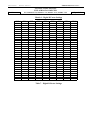
This table is used as the tolerance for vertical speed. For values between table rows, linearly
interpolate between the adjacent table points.
VERTICAL
SPEED
FPM
20000
6000
4000
2000
1000
500
200
100
50
0
-50
-100
-200
-500
-1000
-2000
-4000
-6000
-20000
TOLERANCE
± FPM
1000
300
200
100
50
45
45
45
45
45
45
45
45
45
50
100
200
300
1000
Table 3 - Vertical Speed Tolerance
IM2830-AXS4M.DOC
IM2830-AXS4
DIRECTORY: 962830A-X-S-4
Shadin Avionics
INSTALLATION MANUAL
FUEL/AIR DATA COMPUTER
Rev: M
P/N 962830A-X-S-4, 962830A-1-S-4, 962830A-2-S-4, 962830A-3-S-4
Page: 2-4
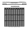
This table is used as the tolerance for MACH Number. For values between table rows, linearly
interpolate between the adjacent table points.
ALTITUDE
TOLERANCE
FEET
MACH
± MACH
0
.3
.012
.4
.012
.5
.010
.6
.0075
.4
.012
.5
.010
.6
.0075
.7
.005
.4
.012
.5
.010
.6
.0075
.7
.005
.6
.0075
.7
.005
.80
.005
.90
.005
.95
.0075
.70
.005
.80
.005
.90
.005
.95
.0075
.75
.005
.90
.005
.95
.0075
1.00
.015
10,000
20,000
30,000
40,000
50,000
Table 4 - MACH Tolerance
IM2830-AXS4M.DOC
IM2830-AXS4
DIRECTORY: 962830A-X-S-4
Shadin Avionics
INSTALLATION MANUAL
FUEL/AIR DATA COMPUTER
P/N 962830A-X-S-4, 962830A-1-S-4, 962830A-2-S-4, 962830A-3-S-4
Rev: M
2.3
Page: 2-5
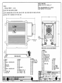
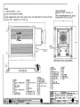
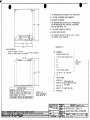
Dimensions (including mounting rack)
Size: 7.4" L x 4.3" H x 3.9" W
Weight: 36 oz.
2.4
Power Requirements
System Power required:
2.5
28 VDC @ 1300 mA
14 VDC @ 900 mA
Output Data
1. Electric Format: RS-422 or RS-232
2. ARINC 429 low/high speed GAMA (Has to be configured at the factory)
See paragraph 2.5.3 for ARINC 429 output data capabilities.
2.5.1
Serial Output Data Parameters
Fuel Group
L. ENG. Fuel Flow
R. ENG. Fuel Flow
Fuel Used Total
Total Fuel Used
Fuel Used L. ENG.
Fuel Used R. ENG.
Fuel Remaining
NM/Fuel Unit (ground)
Fuel to Destination
Fuel at Destination
AIR DATA Group
Pressure Altitude (PALT)
Density Altitude
Barometric Corrected Altitude
Indicated Air Speed (IAS)
True Air Speed (TAS)
Vertical Speed
True Air Temperature (TAT)
Outside Air Temperature (OAT)
Drift Angle
Magnetic Heading
Rate of Turn
MACH Number
Wind Direction and Speed
Baro Correction (mb #1)
Baro Correction (hg”)
Note: Not all parameters will be available to all navigational receivers. Contact the manufacturer for display
capabilities.
IM2830-AXS4M.DOC
IM2830-AXS4
DIRECTORY: 962830A-X-S-4
Shadin Avionics
INSTALLATION MANUAL
FUEL/AIR DATA COMPUTER
P/N 962830A-X-S-4, 962830A-1-S-4, 962830A-2-S-4, 962830A-3-S-4
Rev: M
Page: 2-6
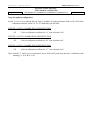
2.5.2 ARINC 429 (GAMA) Output Labels
In Table 5 – ARINC Label Configuration below, the heading row containing the numbers 1-A
indicates the setting of the ARINC rotary switch on the back of the unit. The number in the cell at
the intersection of an ARINC switch setting and an ARINC label number is the repeat time in
msec for that label. Zero indicates that the label is not generated with that switch setting.
Tolerance on the rate is ± 10% averaged over one second.
LABEL
074G
075G
100
113G
114
115
116
147G
203
204
205
206
210
211
212
213
244
251G
252
275G
300
303G
304G
305G
306G
307G
310
311
312
313
314
315
316
320
321
347
351G
352G
371
Description
Flight Plan Header
Active Waypoint To/From
Selected Course
Waypoint Group Checksum
Desired Track (True)
Waypoint Bearing (True)
Cross Track Distance
Magnetic Variation
PALT (1013.25 mB)
PALT (Baro Corrected)
MACH
Indicated Airspeed (IAS)
True Airspeed
OAT
Vertical Speed (IVS)
TAT (Static)
Total Fuel Flow
Distance To Go
Time To Go
LRN Status Word
Navigation Aid Info
Waypoint Group Header
Message ID Characters 1-3
Message ID Characters 4-6
Waypoint Latitude
Waypoint Longitude
Present Latitude
Present Longitude
Ground Speed
True Track
True Heading
Wind Speed
Wind Direction (True)
Magnetic Heading
Drift Angle
Left/Right Fuel Flow
Distance to Final Destination
Time to Final Destination
Equipment ID
0
1000
100
0
100
50
50
50
200
0
0
0
0
100
0
0
0
0
200
200
200
100
100
100
100
100
100
200
200
50
0
0
100
100
0
50
200
0
0
0
1
2
3
4
5
6
7
8
9
A
0
0
0
0
0
0
0
0
200
200
200
0
100
200
200
200
0
0
0
200
0
0
0
0
0
0
0
0
0
0
0
100
100
100
50
200
0
0
0
0
0
0
0
0
0
0
0
50
50
50
50
0
0
50
0
0
0
0
0
0
0
0
0
0
0
0
0
0
0
0
0
0
0
0
0
0
0
0
0
0
200
0
50
50
50
200
200
200
200
200
100
200
200
200
0
200
200
200
0
0
0
0
0
0
200
200
50
200
100
100
100
100
50
200
0
0
0
1000
100
200
100
50
50
50
200
0
0
0
0
0
0
0
0
0
200
200
200
100
100
100
100
100
100
200
200
50
200
100
100
100
100
50
200
0
0
0
1000
100
200
100
50
50
50
200
200
0
200
0
100
0
0
200
0
0
0
200
100
100
100
100
100
100
200
200
50
200
0
100
100
0
0
0
200
200
200
0
0
200
0
50
50
50
200
200
200
200
200
100
200
200
200
0
200
200
0
0
0
0
0
0
0
200
200
50
200
100
100
100
100
50
200
0
0
0
0
0
0
0
0
0
0
0
200
200
200
200
100
200
200
200
100
0
0
0
0
0
0
0
0
0
0
0
0
0
0
0
0
0
0
200
0
0
0
0
0
0
0
0
0
0
0
100
100
0
100
100
0
0
100
0
0
0
0
0
0
0
0
0
0
0
0
0
0
0
0
0
0
0
200
0
0
0
0
0
0
0
0
0
0
0
50
50
0
50
50
0
50
0
0
0
0
0
0
0
0
0
0
0
0
0
0
0
0
0
0
0
0
0
0
0
0
0
0
0
0
0
0
0
0
50
50
0
50
50
0
50
50
0
0
0
0
0
0
0
0
0
0
0
0
0
0
0
0
0
0
0
0
0
0
0
Table 5 – ARINC Label Configuration
IM2830-AXS4M.DOC
IM2830-AXS4
DIRECTORY: 962830A-X-S-4
Shadin Avionics
INSTALLATION MANUAL
FUEL/AIR DATA COMPUTER
P/N 962830A-X-S-4, 962830A-1-S-4, 962830A-2-S-4, 962830A-3-S-4
Rev: M
2.5.3
Page: 2-7
ARINC 429 Labels Associated with Switch Settings
0 - Honeywell SPZ-5000 for Cessna
1 - Bendix KLN90B or Global GNSXC(LS)
2 - HUD-Heads Up Display for Flt Visions
3 - UNS1
6 - Trimble 8100 (No label 275)
7 - TNL-8100
8 - Collins FMS 800 (100 ms rate)
9 - Mk VII GPWS (50 ms rate)
4 - EFIS40/50
A – Mk VI & VIII EGPWS (50 ms rate)
5 - ASINC Airshow Cabin Display
Note that 3 and 6 are the same except for label 275.
The following is a list of the different switch settings that the ARINC switch may be set to. The
ARINC switch position is shown in section 9.2.
0
-
1
-
Long Range Nav function of Honeywell SPZ-5000 Flight Guidance/EFIS System
installed on the Cessna Citation Jet Aircraft.
Bendix to Global/Cabin Info System installed on the Cessna Citation Jet Aircraft.
2
-
Reserved
3
-
8100, UNS1
4
-
Bendix/King EFIS 40/50
5
-
ASINC Airshow
6
-
7
-
8100, UNS1, except no label 275. Use when there is no serial navigation data
being received by the ADC2000.
TNL-8100, with total fuel flow label 244
8
-
Collins FMS 800 (100 ms rate)
9
-
Allied Signal, Mk VII GPWS (50 ms rate)
A
-
Allied Signal, Mk VI and VIII EGPWS (50 ms rate)
IM2830-AXS4M.DOC
IM2830-AXS4
DIRECTORY: 962830A-X-S-4
Shadin Avionics
INSTALLATION MANUAL
FUEL/AIR DATA COMPUTER
P/N 962830A-X-S-4, 962830A-1-S-4, 962830A-2-S-4, 962830A-3-S-4
Rev: M
2.5.4
Page: 2-8
Start-Up Temperature and Times for Output Data Valid
Typical times for Output Data Valid
Typical Time for
Output Data Valid
Start Temperature
< 1 minute
≈ 2.5 minutes
≈ 3.5 minutes
+23°C
-20°C
-55°C
In the Serial Output Data, the “Q” record is used to report if the ADC has completed its warm-up period
and the Altitude/Airspeed Data is accurate.
“Q” Record
2.6
=
=
0
1
=
=
PALT/IAS data valid
PALT/IAS data not valid
Limitations
2.6.1
Warm-up time
The Pressure Altitude, Indicated Airspeed, Vertical Speed, and Barometric Altitude are not valid
until the “Q” record is valid (i.e. a value of “0”). The installer is responsible to ensure that only
valid data is displayed.
2.6.2 Supplemental equipment
All Shadin F/ADC(s) and ADC(s) are not designed to replace factory installed AIR DATA fuel
flow systems or other gauges. The are not intended to be used as a primary system to drive
altimeters or airspeed indicators. The F/ADC fuel section is not a fuel quantity system and
therefore reports only what was manually entered by the operator.
2.6.3
Static Source Error Correction (SSEC),
Pitot Source Error Correction (PSEC)
For certain models of aircraft, the Fuel/AIR DATA System will make corrections to pressure
altitude by compensating for static source error. For some of these models, the Fuel/AIR DATA
System will make corrections to indicated airspeed by compensating for pitot source error.
The System does not provide true and absolute readings for all circumstances. It makes no
altitude corrections when the uncorrected IAS is below 100 knots, and it makes no airspeed
corrections when the uncorrected IAS is below 150 knots. It does not account for other factors,
such as the current useful weight, that contribute to static source error and pitot source error.
Rather, the Fuel/AIR DATA System performs calculations based solely on indicated airspeed and
pressure altitude. The SSEC / PSEC corrections were derived from specific aircraft data referred
to in section 2.6.4. To configure the Shadin F/ADC for a specific aircraft model refer to section 9.
IM2830-AXS4M.DOC
IM2830-AXS4
DIRECTORY: 962830A-X-S-4
Shadin Avionics
INSTALLATION MANUAL
FUEL/AIR DATA COMPUTER
Rev: M
P/N 962830A-X-S-4, 962830A-1-S-4, 962830A-2-S-4, 962830A-3-S-4
Page: 2-9
2.6.4 SSEC/PSEC LISTING
Beechcraft Beechjet-400 (SSEC only)
Airplane Flight Manual, BeechJet 400, Section 6, Performance
FAA approved 1/86
Altitude Correction
Revision A9 14/92
Copilot System
Boeing 707-321B Advanced
SSEC
Airplane Flight Manual, Boeing 707, Section IV, Performance
FAA approved 3/27/69, D6-1588
Altitude Calibration
Revision 2/4/69
Pilot & Copilot
PSEC
Airplane Flight Manual, Boeing 707, Section IV, Performance
FAA approved 9/20/66, D6-1588
Airspeed Calibration
Pilot & Copilot
Page 6-14
Figure 6-8
Page 19
FLAPS UP
Page 18
FLAPS UP
Cessna 500 (SSEC only)
Airplane Flight Manual, Cessna/Citation Model 500, Section IV, Performance
FAA approved Aug 7/74
Altitude Correction
Figure 4-7
Revision 53 - Dated 11 Dec 85
Pilot & Copilot system
Page 4-17.1
Cessna 501 (SSEC only)
Airplane Flight Manual, Cessna/Citation I SP Model 501, Section IV, Performance
FAA approved
Altitude Correction
Figure 4-5
Original
Pilot & Copilot system
Page 4-15
NOTE: Uses same Hardware configuration as Cessna 500
Cessna 525 (SSEC only)
Airplane Flight Manual Model 525
Altitude Correction
Pilot & Copilot system
Rept FT525-4
Page 47
Cessna 550 (SSEC only)
Airplane Flight Manual, Cessna/Citation II Model 550, Section IV, Performance
FAA approved
Altitude Correction
Figure 4-5
Original
Pilot & Copilot system
Page 4-15
Cessna 560 (SSEC only)
Airplane Flight Manual, Model 560, S/N 259 & Below, Section IV, Performance
FAA approved
Altitude Correction
Figure 4-5
Original
Pilot & Copilot system
Page 4-17
IM2830-AXS4M.DOC
IM2830-AXS4
DIRECTORY: 962830A-X-S-4
Shadin Avionics
INSTALLATION MANUAL
FUEL/AIR DATA COMPUTER
Rev: M
P/N 962830A-X-S-4, 962830A-1-S-4, 962830A-2-S-4, 962830A-3-S-4
Page: 2-10
SSEC/PSEC LISTING (Continued)
Cessna 560 (SSEC only)
Airplane Flight Manual, Model 560 , S/N 260 & Up, Section IV, Performance
FAA approved
Altitude Correction
Figure 4-5
56FMA-00
Pilot & Copilot system
Page 4-19
Cessna Citation S550 (SSEC only)
Airplanes -0115 through -0160 Except Airplanes Incorporating SBS550-32-7 and Airplanes -0001
through-0114 Incorporating SBS550-32-1 but not SBS550-32-7.
Section IV - Performance, Standard Charts
FAA approved
Altimeter Position Correction
Revision 37
Pilot & Copilot
Douglas DC-8
SSEC
Airplane Manual, Douglas DC-8, Section IV, Performance
FAA approved
Altitude Correction
DAC-33161 10/1/66
Pilot & Copilot system
PSEC
Airplane Manual, Douglas DC-8, Section IV, Performance
FAA approved
Airspeed Correction
DAC-33161 10/1/66
Pilot & Copilot system
Falcon 10 (SSEC only)
Airplane Flight Manual, Section 6. Performance, 7 Position Error
FAA approved 10/17/73
Position Error
Revision 14, 6/6/78
Pilot & Copilot
Falcon 20-C, D, E (SSEC only)
Maintenance Instruction Manual, 34-18-03
Sept 1/77
Altitude Correction
CS-143
Copilot system
Falcon 20-F (SSEC only)
Maintenance Instruction Manual, 34-18-03
DTM30528
Altitude Correction
DGAC Approved
Copilot system
Pages 4-17, 4-18
Figure 4-5
Page 20
Page 11
Page 6-27
Page A48
Section 5
Subsection 20
Page 4
IM2830-AXS4M.DOC
IM2830-AXS4
DIRECTORY: 962830A-X-S-4
Shadin Avionics
INSTALLATION MANUAL
FUEL/AIR DATA COMPUTER
Rev: M
P/N 962830A-X-S-4, 962830A-1-S-4, 962830A-2-S-4, 962830A-3-S-4
Page: 2-11
SSEC/PSEC LISTING (Continued)
Falcon 50
SSEC
Airplane Flight Manual, Section 5. Performance
Page 5.25.2
DGAC approved
Copilot (for A/C equipped with one ADC)
Revision 24
PSEC
Airplane Flight Manual, Section 5. Performance
Page 5.25.2
DGAC approved
Pilot (normal) and Copilot MACH Indicators
Revision 24
Lear 24 (SSEC only)
Airplane Manual, LearJet Model 24, Section IV, Performance
FAA approved 3/17/66
Altitude Correction
Revised 7/19/68
Pilot & Copilot system
Figure 4-10
Page 4-16
Lear 25D (SSEC only)
Airplane Manual, LearJet 25D/F AFM, Performance
FAA approved 10/14/86
Altitude Correction
FM-018 Release A
Copilot system
Figure 5-10
Page 5-18
Learjet 35 (SSEC only)
Flight Manual, LearJet 35, Normal System, Flaps up, Gear up
Page 5-18
FAA approved, 4/30/76
Altitude Position Correction
Figure 5-10
Reissued 2/25/81
Pilot’s Altimeter- STBY & Copilot’s Altimeter
Learjet 55 (SSEC only)
Gates Learjet 55, APM, Performance Data, Flaps up, Gear up
FAA approved, 3-17-81
Altitude Position Correction
Change 13
Page 5-20
Figure 5-11
Lockheed Jetstar (SSEC only)
Airplane Flight Manual, Performance Data, Weight = 32,000 Lb., Clean Configuration: Leading
Edge Flaps up, Trailing Edge Flaps up, Landing Gear up
Page 4-25
FAA approved, 12/14/76
Altimeter Installation Correction
Figure 4-15
IM2830-AXS4M.DOC
IM2830-AXS4
DIRECTORY: 962830A-X-S-4
Shadin Avionics
INSTALLATION MANUAL
FUEL/AIR DATA COMPUTER
Rev: M
P/N 962830A-X-S-4, 962830A-1-S-4, 962830A-2-S-4, 962830A-3-S-4
Page: 2-12
SSEC/PSEC LISTING (Continued)
Mitsubishi MU-300 (SSEC only)
Airplane Flight Manual, Diamond IA, Section 6, Performance
FAA approved Jan 11/84
Altitude Correction
Copilot system
Figure 6-8
Page 6-20
Raytheon Hawker HS-125-3A (SSEC only)
Airplane Manual,
Document No. H.S.1.10
Static Position Error
CAA Approved
Correction to Altimeter
Section 5
Figure 5-4
Page 13
Raytheon Hawker HS125-700A (SSEC only)
125 Crew Manual, First Officer, Section 2, Flaps Retracted
Static Position Correction to Altimeter
Revision :G, 4/77
Sabreliner 60 (SSEC only)
SabreLiner Pilot’s Manual, SR 75-064, Weight = 16,000 Lb.
9/1/76
Altitude Calibration
Page 2-30
Figure 6
Figure 7-2
Sabreliner 65 (SSEC only)
Pilots Manual, SR-78-028
Altitude Correction
Pilot & Copilot system
Westwind 1124A (SSEC only)
Airplane Flight Manual, 1124A , Section V, Performance
CAA approved
Altitude Correction
Figures 5-13, Flaps 0
Copilot system
NOTE: Gross Weight averaged at 18,750 lbs.
Figures 7-1 through 7-5
265-65-7-31,32A,33
Pages V-25
IM2830-AXS4M.DOC
IM2830-AXS4
DIRECTORY: 962830A-X-S-4
Shadin Avionics
INSTALLATION MANUAL
FUEL/AIR DATA COMPUTER
Rev: M
2.7
P/N 962830A-X-S-4, 962830A-1-S-4, 962830A-2-S-4, 962830A-3-S-4
Page: 2-13
Part Numbering Scheme
P/N 962830 A - Y - S - 4
Quick Start PALT/IAS
ADC2000 with MS Connector
Fuel Sensor Type
Y = X, None
Y = 1, Digital
Y = 2, Sine wave
Y = 3, DC voltage
Shadin OAT Probe
IM2830-AXS4M.DOC
IM2830-AXS4
DIRECTORY: 962830A-X-S-4
Shadin Avionics
INSTALLATION MANUAL
FUEL/AIR DATA COMPUTER
P/N 962830A-1, 962830A-2, 962830A-3
Rev: M
2.8
Page: 2-14
Electrical Interface Specifications
The specifications for the interfaces heading, fuel flow and baro are listed in this section.
2.8.1
Heading Interface
The heading interface follows the ARINC 407 standard (line voltage of 11.8 Vrms).
Synchro Leg
H
X
Y
2.8.2
Input Impedance
10 kohm
17 kohm
17 kohm
Fuel Flow Interfaces
There are three basic types of fuel flow interfaces supported. The interface type is defined in the
ADC2000 part number. Refer to section 2.7 for the part numbering scheme.
2.8.2.1 Digital Fuel Flow Interface
The are two possible installations for the digital fuel flow interface, the first is that the ADC is
connected to a dedicated fuel flow transmitter, and the second is that the ADC is connected into a
fuel flow system.
Dedicated Transmitter
Fuel Flow Interface Input Impedance
47 kohm
Shared Transmitter
Under normal operating conditions the voltage swing (the signal amplitude) can be calculated
using Vs = [R/(R + 47 k)]*5 Vdc – 0.5Vdc, where R is the input impedance of the aircraft fuel
flow indicator.
For example with an input impedance R = 1 Mohm, the voltage swing Vs = 4.27 Vdc
With the fuel flow information is encoded in frequency and not amplitude, the loading effects do
not produce an error provided the aircraft indicator can detect the signal transitions.
IM2830-AXS4M.DOC
IM2830-AXS4
DIRECTORY: 962830A-X-S-4
Shadin Avionics
INSTALLATION MANUAL
FUEL/AIR DATA COMPUTER
P/N 962830A-1, 962830A-2, 962830A-3
Rev: M
Page: 2-15
2.8.2.2 Sine Wave Fuel Flow Interface
The interface source signal amplitude varies with frequency. Listed in the table below are the
input impedance vs. peak to peak input voltages of the ADC2000 under normal operating
conditions.
Input Impedance
2 Mohm
24.5 kohm
Maximum Input Voltage
Input Voltage
Input voltage less than or equal to 1.0 Vpp
Input voltage greater than 1.0 Vpp
10 Vpp
2.8.2.3 DC Voltage Fuel Flow Interface
The DC voltage fuel flow interface has a differential input. The specifications under normal
operating conditions are listed below.
2.8.3
Positive input
Negative input
greater than 100 Mohm
greater than 100 Mohm
Maximum Input Voltage
10.2 Vdc
Baro Interface
The baro interface requires a three-wire connection to the potentiometer housed in the aircraft
altimeteri. The three connections are the high side, low side and wiper. The specifications under
normal operating conditions are listed below.
i
Input Impedance high side
Input Impedance low side
Input Impedance wiper
greater than 100 Mohm
greater than 100 Mohm
greater than 100 Mohm
Maximum Input Voltage
± 12 Vdc
The altimeters supported are listed in section 9.2 and are dependent upon the ADC2000 software version level.
IM2830-AXS4M.DOC
IM2830-AXS4
DIRECTORY: 962830A-X-S-4
Shadin Avionics
INSTALLATION MANUAL
FUEL/AIR DATA COMPUTER
P/N 962830A-1, 962830A-2, 962830A-3
Rev: M
2.9
Statistical Specifications
2.9.1
Mean Time Between Failures
MTBF:
17,660 hours
Page: 2-16
IM2830-AXS4M.DOC
IM2830-AXS4
DIRECTORY: 962830A-X-S-4
Shadin Avionics
INSTALLATION MANUAL
FUEL/AIR DATA COMPUTER
Rev: M
3.0
P/N 962830A-X-S-4, 962830A-1-S-4, 962830A-2-S-4, 962830A-3-S-4
CERTIFICATION
TSO C106, C44a
Environmental Categories RTCA/DO-160B
Temp. ALT
Temp. Variation
Humidity
Shock & Vibration
Magnetic Effect
Power Input
Voltage Spike
AF Conducted Susceptibility
Induced Signal Susceptibility
RF Susceptibility
RF Emission
F2
B
A
P,K,S,M, N, O
B
B
B
B
B
A
B
Page: 3-1
IM2830-AXS4M.DOC
IM2830-AXS4
DIRECTORY: 962830A-X-S-4
Shadin Avionics
INSTALLATION MANUAL
FUEL/AIR DATA COMPUTER
Rev: M
4.0
P/N 962830A-X-S-4, 962830A-1-S-4, 962830A-2-S-4, 962830A-3-S-4
Page: 4-1
PLACING AN ORDER
Please know the aircraft year and model number, its serial number, and the engine make and
model number when you call to place orders. Information on the fuel flow system previously
installed in the aircraft and any communication interface (RS-232, RS-422 and ARINC 429)
information may also prove useful.
We may request a wiring diagram of the aircraft's fuel flow system and transducer and/or Kfactors.
When interfacing an altimeter to the Shadin barometric pressure potentiometer option consult the
list of supported altimeters contain in this manual or contact the Shadin Technical Support.
IM2830-AXS4M.DOC
IM2830-AXS4
DIRECTORY: 962830A-X-S-4
Shadin Avionics
INSTALLATION MANUAL
FUEL/AIR DATA COMPUTER
P/N 962830A-X-S-4, 962830A-1-S-4, 962830A-2-S-4, 962830A-3-S-4
Rev: M
5.0
INSTALLATION PROCEDURE
5.1
General
Page: 5-1
The conditions and tests required for TSO approval of this article are minimum performance
standards. It is the responsibility of those installing this article either on or within a specific type
or class of aircraft to determine that the aircraft installation conditions are within the TSO
standards. TSO articles must have separate approval for installation in an aircraft. The article
may be installed only if performed under 14 CFR part 43 or the applicable airworthiness
requirements.
All work must conform to AC 43.13-1B
5.2
F/ADC Location Selection
The Fuel AIR DATA Computer should be mounted in a dry, temperature stable location with
enough distance from motors, pulse generating equipment, relays and cables carrying high DC or
AC current to avoid interference with low level signals of the OAT and fuel flow.
The equipment may be installed in non-pressurized and non-controlled temperature locations.
In considering the location, keep in mind that the F/ADC requires signals from the fuel flow, the
OAT probe, heading system and the pitot and static lines. Placement in the front section of the
aircraft is favorable, in order to avoid running all of these signals to the tail of the aircraft.
5.3
Mounting the F/ADC
Consult the Drawings 4028-857 or 4028-871 or 4028-872 or 4028-873 and Drawing 4028-395,
before mounting the ADC2000. Use the recommended hardware. Any orientation is acceptable.
Make sure that the computer is not the lowest point in the pitot and static system, to reduce the
chances of collecting moisture or water in it. Form a water trap, if necessary.
IM2830-AXS4M.DOC
IM2830-AXS4
DIRECTORY: 962830A-X-S-4
Shadin Avionics
INSTALLATION MANUAL
FUEL/AIR DATA COMPUTER
P/N 962830A-X-S-4, 962830A-1-S-4, 962830A-2-S-4, 962830A-3-S-4
Rev: M
5.4
Page: 5-2
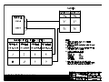
Mounting the OAT Probe
1. Refer to drawing 4028-005 and OAT Probe Assy Kit 681201-1. Use the supplied stiffener to
support the probe. Keep the probe away from transmitting antennas and static ports of
autopilots to avoid interference.
2. Refer to drawing 4028-874. The OAT probe power is supplied from (red wire) J1:52. The OAT
signal is the white wire from J1:33. At least the signal wire to the ADC2000 should be shielded
and terminated at the ADC2000 only.
3. The sun shield must be installed for proper indication of OAT.
4. For single engine installation, avoid mounting the OAT probe on the belly of the aircraft to
avoid erroneous reading due to the presence of hot exhaust gases.
5. Below is an OAT to ºC to input current conversion chart for use in testing the OAT Probe.
OAT ºC
-60
-50
-40
-30
Input µA
213
223
233
243
OAT ºC
-20
-10
0
+10
Input µA
253
263
273
283
OAT ºC
+20
+30
+40
+50
Input µA
293
303
313
323
OAT ºC
+60
Input µA
333
1°C = 1 μA
IM2830-AXS4M.DOC
IM2830-AXS4
DIRECTORY: 962830A-X-S-4
Shadin Avionics
INSTALLATION MANUAL
FUEL/AIR DATA COMPUTER
P/N 962830A-X-S-4, 962830A-1-S-4, 962830A-2-S-4, 962830A-3-S-4
Rev: M
5.5
Page: 5-3
Connection to the Fuel Flow Sensor
1.
If the aircraft is not equipped with a fuel flow source, refer to the STC covering the
installation of the fuel flow transducer on the engine.
2.
When connecting to any fuel transducer, Shadin recommends using a 3 conductor, 22 gauge,
shielded wire with the shield terminated at the AIR DATA only.
3.
Note that for single engines all fuel flow types should use left side inputs only.
4.
*Install the transducers according to the engine STC, using Drawing 4028-875 to connect the
fuel flow transducer to the computer.
5.
*If the aircraft is equipped with a digital fuel flow system using transducer (P/N 680501), use
Drawing 4028-875 (refer to note 1 on that drawing) and the STC drawing covering the
installation.
6.
Before hooking to an existing fuel system in a turbine or jet application, consult all
installation drawings contained in this manual.
7.
*If the aircraft is equipped with a DC fuel flow system, use Drawing 4028-875 (for P/N
962830A-3-S-4) and the STC covering the installation.
8.
*If the aircraft is equipped with a sine wave pickup coil type of fuel flow transducer, use
Drawing 4028-875 (for P/N 962830A-2-S-4).
9.
Make sure that the system is initialized with the proper transducer K factor for a digital or
sine systems and with the proper airframe make and model for the DC fuel flow systems. See
the attached tables in section 10.0.
* Consult section 11 for specific aircraft installation wiring drawings.
IM2830-AXS4M.DOC
IM2830-AXS4
DIRECTORY: 962830A-X-S-4
Shadin Avionics
INSTALLATION MANUAL
FUEL/AIR DATA COMPUTER
P/N 962830A-X-S-4, 962830A-1-S-4, 962830A-2-S-4, 962830A-3-S-4
Rev: M
5.6
Page: 5-4
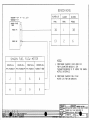
Connection to the Heading Source
The system is designed to interface with any ARINC-407 heading system (X,Y,Z) with no effect
on the heading system or the bootstrap.
XYZ
Heading
ARINC
407
FUEL
AIR
DATA
J1
Collins
328A-2A
2P1
X
Y
Z
H
C
5
4
7
6
7
11
4
3
26
22
Collins
HSI331A
P1
S
T
U
V
W
Collins
MCS
65
P1
Collins
328A-5
25
40
24
6
5
32
22
12
53
57
King
KI525A
P2
s
v
t
r
u
King
KSG105
P1
t
p
k
c
f
Sperry
Gyrosyn
Comp.
P1
SigmaTek
DG
L
M
K
H
J
A
B
D
E
H
Sandel
SN3308
P1
P2
25
6
4
4
4
The C wire (AC common) and the Z wire must be connected together at the source (bootstrap).
IM2830-AXS4M.DOC
IM2830-AXS4
DIRECTORY: 962830A-X-S-4
Shadin Avionics
INSTALLATION MANUAL
FUEL/AIR DATA COMPUTER
P/N 962830A-X-S-4, 962830A-1-S-4, 962830A-2-S-4, 962830A-3-S-4
Rev: M
5.7
Page: 5-5
Connection to the Pitot and Static Lines
The pitot static line should be cut and a tee installed, to tap into these lines. Use the appropriate
type of fittings to match the type installed in the aircraft. Refer to CFR part 43, appendix E for
approved practices in installing and verifying these connections.
PITOT/STATIC adapter helpful hints
To make an adapter for the Shadin ADC2000, the following parts could be used. It is recommended to use all
aluminum fittings.
Existing Pitot/Static lines
AN910-1D
AN816-2D
#2 Hose(with female fittings)
AN910 DASH NUMBER
BRASS
ALUM. ALLOY
-1
-2
-3
-4
-6
-8
-1D
-2D
-3D
-4D
-6D
-8D
PIPE
SIZE
1/8”
1/4”
3/8”
1/2”
3/4”
1”
AN816 DASH NUMBER
STEEL ALUM. ALLOY
-2
-3
-4
-5
-6
-8
-10
-12
-16
MS20825 TEE
STEEL
ALUM. ALLOY
-2
-3
-4
-5
-2D
-3D
-4D
-5D
TUBE
O. D.
PIPE
THREAD
1/8”
3/16”
1/4”
5/16”
3/8”
1/2”
5/8”
3/4”
1”
1/8”
1/8”
1/8”
1/8”
1/4”
3/8”
1/2”
3/4”
1”
-2D
-3D
-4D
-5D
-6D
-8D
-10D
-12D
-16D
TUBE
O. D.
PIPE
THREAD
1/8”
3/16”
1/4”
5/16”
1/8”
1/8”
1/8”
1/8”
HOSE: Stratoflex 193-2 or Aeroquip 306-2 with MS27404 (P/N 311-2D) on each end.
Air source
MS20825 Tee
AN910
AN816
MS27404
AN816
ADC2000
IM2830-AXS4M.DOC
IM2830-AXS4
DIRECTORY: 962830A-X-S-4
Shadin Avionics
INSTALLATION MANUAL
FUEL/AIR DATA COMPUTER
P/N 962830A-X-S-4, 962830A-1-S-4, 962830A-2-S-4, 962830A-3-S-4
Rev: M
5.8
5.9
Page: 5-6
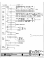
Connection to the Navigation Management System
1.
Use installation wiring diagram 428-874 to connect the Fuel Air Data Computer's Connector
J1 to the navigation management system.
2.
A 2 amp. circuit breaker should be used for powering the system. Mark the circuit breaker by
engraving, painting or other approved method.
3.
Keep the cables away from power cables, DME and transponder cables.
4.
Refer to the specific Nav Receiver Installation Manuals for details.
5.
If the ARINC 429 output is used, refer to the digital EFIS or flight management installation
manual and sections 2.5.2 – 2.5.4 in this manual.
Connection to the Altimeter Baro Pot (optional)
1. Use the Installation wiring diagram 4028-A44 to connect the altimeter to J1 of the Air Data
computer.
2. Remember to select the correct altimeter type in the software configuration. See section 9 in
this manual.
5.10
Post Installation Checkout
1.
The pitot and static system must be checked for leaks.
2.
Operate the Navigation Management System; select the altitude and airspeed pages. Use the
static and pitot test system to check the accuracy of the readout in the Navigation
Management System pages.
3.
Select heading page. Slew compass through 360°. The error should be within +1°.
4.
Select the OAT page. Compare to the reported ambient temperature. The error should be
±1°C.
5.
Run the engines and select the fuel flow page. Compare the fuel flow readout with the engine
manufacturer's fuel flow charts under the ambient temperature and pressure conditions.
6.
Set the Barometric pressure to a known value and verify that the reported barometric pressure
at the Navigational Receiver is that value + 0.01 In.Hg. (if the option is installed)
IM2830-AXS4M.DOC
IM2830-AXS4
DIRECTORY: 962830A-X-S-4
Shadin Avionics
INSTALLATION MANUAL
FUEL/AIR DATA COMPUTER
P/N 962830A-X-S-4, 962830A-1-S-4, 962830A-2-S-4, 962830A-3-S-4
Rev: M
6.0
Page: 6-1
OPERATING INSTRUCTIONS
1.
Power the avionics DC buss and the Navigation Management System.
2.
After the warm-up period density altitude and PALT are available. IAS will be available but
will be out of range until actual airspeed is available. Winds aloft will be available if the IAS
is greater than 40 Kts and magnetic heading is within 40° of magnetic track.
3.
Fuel Flow, Fuel Used, Fuel Remaining, Heading and OAT will be available after power-up.
4.
Refer to the specific Nav Receiver Operator's Manual for page selection of various data.
IM2830-AXS4M.DOC
IM2830-AXS4
DIRECTORY: 962830A-X-S-4
Shadin Avionics
INSTALLATION MANUAL
FUEL/AIR DATA COMPUTER
P/N 962830A-X-S-4, 962830A-1-S-4, 962830A-2-S-4, 962830A-3-S-4
Rev: M
7.0
Page: 7-1
INITIALIZATION
1.
The system requires initialization of K factor for fuel flow transducers or aircraft model for
DC fuel flow sensors. Refer to Table 1 analog for fuel flow and Table 2 or Table 3 for
digital or sinewave fuel flow.
2.
Refer to the specific Navigational Receiver Operator Manuals for the serial port set up.
IM2830-AXS4M.DOC
IM2830-AXS4
DIRECTORY: 962830A-X-S-4
Shadin Avionics
INSTALLATION MANUAL
FUEL/AIR DATA COMPUTER
P/N 962830A-X-S-4, 962830A-1-S-4, 962830A-2-S-4, 962830A-3-S-4
Rev: M
8.0
MAJOR COMPONENTS OF THE SYSTEM
1.
2.
3.
Nav Receiver Input/Output
Fuel/AIR DATA Computer
Outside Air Temperature Probe, P/N 681201( )
Page: 8-1
IM2830-AXS4M.DOC
IM2830-AXS4
DIRECTORY: 962830A-X-S-4
Shadin Avionics
INSTALLATION MANUAL
1
FUEL/AIR DATA COMPUTER
Rev: M
9.0
P/N 962830A-X-S-4, 962830A-1-S-4, 962830A-2-S-4, 962830A-3-S-4
Page: 9-1
CONFIGURING THE AIR DATA
Part number 962830A-YS4 (Y= X, 1, 2 or 3) AIR DATA Computer needs to be configured to
program it for the particular installation. The procedure contained in this Installation Manual is
for software versions 93.02.67 and 93.04.02 and above. There are two methods to accomplish this
task. The first method is to follow the procedures as set forth in the 'ADSETUPF User Manual'.
The second method is to manually enter the information by performing a ‘Loop-Back’ procedure.
9.1
Configuring with 'ADSETUP User Manual'
The 'ADSETUPF User Manual' is a configuration utility that allows setting the ADC configuration
by running a program on a PC. The PC is connected to the AIR DATA via the serial
communication port. See the 'ADSETUPF User Manual' for more details.
IM2830-AXS4M.DOC
IM2830-AXS4
DIRECTORY: 962830A-X-S-4
Shadin Avionics
INSTALLATION MANUAL
FUEL/AIR DATA COMPUTER
Rev: M
9.2
P/N 962830A-X-S-4, 962830A-1-S-4, 962830A-2-S-4, 962830A-3-S-4
Page: 9-2
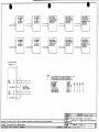
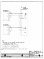
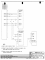
Configuring Manually (Loop-Back)
The switches that are available from the back side of the unit need to be set to the appropriate
positions as determined by the switch settings listed below. After the correct switch positions
have been selected, the unit is powered using the 'Loop-Back' harness (consult drawing number
4028-A62 contained in section 11). The purpose of the 'loop back' harness is to tie the RS-232
transmit and receive ports together. This allows the software, when the unit is powered on, to read
the switch positions. Switch 1 is set to different positions to select the separate stages that the
loopback is performing. There are 2 different ‘loopback’ procedures. Use ‘loopback’ procedure 1
for Software Version 93.02.67. Use ‘loopback’ procedure 2 for software versions 93.04.02 and
above. Note that procedure 1 has 4 stages, and procedure 2 has 5 stages. Remember to cycle
power between stages and that the F/ADC is to be powered on for 1 minute for each stage.
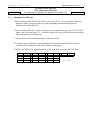
The following figure shows the approximate switch positions:
Connectors
End A
End B
Switches
1
2
3
4
ARINC 429 Switch
VIEW FROM END A
IM2830-AXS4M.DOC
IM2830-AXS4
DIRECTORY: 962830A-X-S-4
Shadin Avionics
INSTALLATION MANUAL
FUEL/AIR DATA COMPUTER
P/N 962830A-X-S-4, 962830A-1-S-4, 962830A-2-S-4, 962830A-3-S-4
Rev: M
Loopback Procedure 1 for Software Version 93.02.67
Stage 0 Loopback Configuration:
Switch 1 is set to 0 to indicate that the stage 0 loopback is being performed.
SWITCH 2
0
1
2
3
4
5
6
7
8
9
A
B
C
D
E
F
Fuel Units and Engine Type:
- Gallons
Single Engine
- Liters
"
"
- Lbs 5.8
"
"
- Lbs 6.71
"
"
- Kilograms
"
"
- Lbs 6.5
"
"
- Lbs 6.3
"
"
- (not used)
"
"
- Gallons
Twin Engine
- Liters
"
"
- Lbs 5.8
"
"
- Lbs 6.71
"
"
- Kilograms
"
"
- Lbs 6.5
"
"
- Lbs 6.3
"
"
- (DO NOT USE)
SWITCH 3
0
1
2
3
4
5
6
7
8-E
F
9600 BAUD Loran Input Type:
- Trimble
- ARNAV
- Bendix or IIMorrow NMS2001, 800, 820, GX50/55/60, 9600
- Garmin
- Northstar (1200 or 9600 baud, 1200 is default for Northstar)
- Foster
- IIMorrow 611, 612 and 618 (1200 baud)
- Shadin Flow Meter
- (DO NOT USE)
- Use this position to make selection on SWITCH 4
SWITCH 4
0
1
2
3-F
Other Loran Input Type:
- Northstar, 1200 BAUD
- Foster, 1200 BAUD
- IIMorrow 611, 612, 618; 1200 BAUD
- (DO NOT USE)
Page: 9-3
IM2830-AXS4M.DOC
IM2830-AXS4
DIRECTORY: 962830A-X-S-4
Shadin Avionics
INSTALLATION MANUAL
FUEL/AIR DATA COMPUTER
P/N 962830A-X-S-4, 962830A-1-S-4, 962830A-2-S-4, 962830A-3-S-4
Rev: M
Stage 1 Loopback Configuration:
Switch 1 is set to 1 to indicate that the stage 1 loopback is being performed.
SWITCH 2
0
1
2
3-F
OAT Probe Type:
- Shadin OAT Probe
- ARINC 575 (DO NOT USE)
- Rosemount 500 Ω (DO NOT USE)
- (DO NOT USE)
SWITCH 3
0
1
2
3
4
5
6
7
8-F
Loran Output Type:
- Format Z - Trimble and Garmin
- Format X - ARNAV
- Generic - DO NOT USE
- Surveyor
- Bendix C – Bendix/King and F/ADC without Barometric Interface
- Bendix D - Bendix/King and F/ADC with Barometric Interface
- Shadin S - IIMorrow GX50, 55, 60
- Bendix B – (fuel only)
- (DO NOT USE)
SWITCH 4
0
1
2
3
4
5
6
7
8
9
A-F
Altimeter Selection for Baro DC Input:
- None
- Type 1
- Type 2
- Type 3
- Type 4
- Type 5
- Type 6
- Type 7
- (DO NOT USE)
- Type 9
- (DO NOT USE)
Page: 9-4
IM2830-AXS4M.DOC
IM2830-AXS4
DIRECTORY: 962830A-X-S-4
Shadin Avionics
INSTALLATION MANUAL
FUEL/AIR DATA COMPUTER
P/N 962830A-X-S-4, 962830A-1-S-4, 962830A-2-S-4, 962830A-3-S-4
Rev: M
Page: 9-5
ALTIMETER TYPES
Type 1:
Kollsman PD 44929-935 (done for Cessna 525).
Type 2:
Bendix/King KEA 130A, and KEA 346 versions (King P/N 066-3062-XX) XX =
08 through 11, versions 00 though 07 have no Baro Potentiometer.
Type 3:
ARINC 575-3 specification for ratio to Altitude Correction calculation.
Kollsman IDC 28007-427, -429,
Kollsman IDC 28704-A1001, -A2001, -A4001, -B4001, -C4001, -D1001, -D2001,
-D4001, -D4101, -4E2101, -F2101, and -495.
Type 4:
Kollsman IDC 28711-621 thru 624.
Type 5:
Kollsman IDC 28007-431, -433,
Honeywell (Sperry) BA-141.
Type 6:
Kollsman IDC 28711-500 series and -600 series.
Type 7:
Kollsman IDC 28711-065 and -066.
Type 8:
Reserved for future use (DO NOT USE).
Type 9:
Aerosonic P/N 102220-1188T, 10420-11968E
IM2830-AXS4M.DOC
IM2830-AXS4
DIRECTORY: 962830A-X-S-4
Shadin Avionics
INSTALLATION MANUAL
FUEL/AIR DATA COMPUTER
P/N 962830A-X-S-4, 962830A-1-S-4, 962830A-2-S-4, 962830A-3-S-4
Rev: M
Stage 2 Loopback configuration:
Switch 1 is set to 2 to indicate that the stage 2 loopback is being performed.
SWITCH 2
0
1
Fuel Filter Type:
-
Injector
Carburetor
SWITCH 3 AND SWITCH 4
0
0
0
1
0
2
0
3
0
4
0
5
0
6
0
7
0
8
0
9
0
A
0
B
0
C
0
D
0
E
0
F
1
0
1
1
1
2
1
3
1
4
1
5
1
6
1
7
1
8
1
9
1
A-F
CORRECTION For SSEC/PSEC Select:
- No correction
- MITSUBISHI MU-300
- CESSNA CITATION 500/501
- CESSNA 525
- CESSNA 550
- Citation 560 SN <=259
- Citation 560 SN >=260
- Citation 650
- Sabreliner 65
- WestWind 1124A
- Lear 24
- Raytheon Hawker HS 125-3A
- Falcon 20-F
- Falcon 20-C, D, E
- Lear 25D
- Douglas DC-8
- Beechjet 400
- Boeing 707-321B
- Cessna Citation S550
- Falcon 10
- Falcon 50
- Raytheon Hawker HS125-700A
- Learjet 35
- Learjet 55
- Sabreliner 60 (SSEC Only)
- Lockheed Jetstar II
- Reserved for future (DO NOT USE)
Page: 9-6
IM2830-AXS4M.DOC
IM2830-AXS4
DIRECTORY: 962830A-X-S-4
Shadin Avionics
INSTALLATION MANUAL
FUEL/AIR DATA COMPUTER
P/N 962830A-X-S-4, 962830A-1-S-4, 962830A-2-S-4, 962830A-3-S-4
Rev: M
Stage 3 Loopback configuration:
Switch 1 is set to 3 to indicate that the stage 3 loopback is being performed.
SWITCH 2, K-FACTOR TABLE SELECTION:
For F/ADC 962830A-1-S-4 and 962830A-2-S-4 only.
0
1
2-F
-
Standard K-FACTOR Matrix 0 - (Table 2 in this manual)
Alternate K-FACTOR Matrix 1- (Table 3 in this manual)
(DO NOT USE)
SWITCH 3, FUEL FLOW DELAY TIME
0
- No Delay
1
- 5 Second Delay
2
- 10 Second Delay
3
- 15 Second Delay
4
- 20 Second Delay
5
- 25 Second Delay
6
- 30 Second Delay
7
- 35 Second Delay
8
- 40 Second Delay
9
- 45 Second Delay
A-F - (DO NOT USE)
SWITCH 4
0
1
2-F
SPECIAL OPTION DESCRIPTION
-ARINC 429 labels 206 (IAS) and 210 (TAS) are not
transmitted if the IAS < 20 knots
-ARINC 429 labels 206 (IAS) and 210 (TAS) are transmitted
as zero knots if the IAS < 20 knots
Reserved – DO NOT USE
Page: 9-7
IM2830-AXS4M.DOC
IM2830-AXS4
DIRECTORY: 962830A-X-S-4
Shadin Avionics
INSTALLATION MANUAL
FUEL/AIR DATA COMPUTER
P/N 962830A-X-S-4, 962830A-1-S-4, 962830A-2-S-4, 962830A-3-S-4
Rev: M
Loopback Procedure 2 for Software Version 93.04.02 and above.
Stage 0 Loopback Configuration:
Switch 1 is set to 0 to indicate that the stage 0 loopback is being performed.
SWITCH 2
0
1
2
3
4
5
6
7
8
9
A
B
C
D
E
F
Fuel Units and Engine Type:
- Gallons
Single Engine
- Liters
"
"
- Lbs 5.8
"
"
- Lbs 6.71
"
"
- Kilograms
"
"
- Lbs 6.5
"
"
- Lbs 6.3
"
"
- (not used)
"
"
- Gallons
Twin Engine
- Liters
"
"
- Lbs 5.8
"
"
- Lbs 6.71
"
"
- Kilograms
"
"
- Lbs 6.5
"
"
- Lbs 6.3
"
"
- (DO NOT USE)
SWITCH 3
0
1
2
3
4
5
6
7
8-E
F
9600 BAUD Loran Input Type:
- Trimble
- ARNAV
- Bendix or IIMorrow Apollo NMS2001, 800, 820
- Garmin
- Northstar
- Foster
- IIMorrow 611, 612 and 618
- Shadin Flow Meter
- (DO NOT USE)
- Use this position to make selection on SWITCH 4
SWITCH 4
0
1
2
3-F
Other Loran Input Type:
- Northstar, 1200 BAUD
- Foster, 1200 BAUD
- IIMorrow 611, 612, 618; 1200 BAUD
- (DO NOT USE)
Page: 9-8
IM2830-AXS4M.DOC
IM2830-AXS4
DIRECTORY: 962830A-X-S-4
Shadin Avionics
INSTALLATION MANUAL
FUEL/AIR DATA COMPUTER
P/N 962830A-X-S-4, 962830A-1-S-4, 962830A-2-S-4, 962830A-3-S-4
Rev: M
Stage 1 Loopback Configuration:
Switch 1 is set to 1 to indicate that the stage 1 loopback is being performed.
SWITCH 2
0
1
2
3-F
OAT Probe Type:
- Shadin OAT Probe
- ARINC 575 (DO NOT USE)
- Rosemount 500 Ω (DO NOT USE)
- (DO NOT USE)
SWITCH 3
0
1
2
3
4
5
6
7
8
9-F
Loran Output Type:
- Format Z - Trimble and Garmin
- Format X - ARNAV
- Generic
- Surveyor
- Bendix C - Bendix/King and F/ADC without Baro Interface
- Bendix D - Bendix/King and F/ADC with Baro Interface
- Shadin S - IIMorrow GX50, 55, 60
- Bendix B – (fuel only)
- Garmin G
- (Do Not Use)
SWITCH 4
0
1
2
3
4
5
6
7
8
9
A
B
C-F
Altimeter Selection for Baro DC Input:
- None
- Type 1
- Type 2
- Type 3
- Type 4
- Type 5
- Type 6
- Type 7
- (DO NOT USE)
- Type 9
- (DO NOT USE)
- Type 11
- (DO NOT USE)
Page: 9-9
IM2830-AXS4M.DOC
IM2830-AXS4
DIRECTORY: 962830A-X-S-4
Shadin Avionics
INSTALLATION MANUAL
FUEL/AIR DATA COMPUTER
P/N 962830A-X-S-4, 962830A-1-S-4, 962830A-2-S-4, 962830A-3-S-4
Rev: M
Page: 9-10
ALTIMETER TYPES
Type 1:
Kollsman PD 44929-935 (done for Cessna 525).
Type 2:
Bendix/King KEA 130A, and KEA 346 versions (King P/N 066-3062-XX) XX =
08 through 11, versions 00 though 07 have no Baro Potentiometer.
Type 3:
ARINC 575-3 specification for ratio to Altitude Correction calculation.
Kollsman IDC 28007-427, -429,
Kollsman IDC 28704-A1001, -A2001, -A4001, -B4001, -C4001, -D1001, -D2001,
-D4001, -D4101, -4E2101, -F2101, and -495.
Type 4:
Kollsman IDC 28711-621 thru 624.
Type 5:
Kollsman IDC 28007-431, -433,
Honeywell (Sperry) BA-141.
Type 6:
Kollsman IDC 28711-500 series and -600 series.
Type 7:
Kollsman IDC 28711-065 and -066.
Type 8:
Reserved for future use (DO NOT USE).
Type 9:
Aerosonic P/N 102220-1188T, 10420-11968E.
Type 10:
Reserved for future use (DO NOT USE).
Type 11:
IDC P/N KTS B45152 10 410
IM2830-AXS4M.DOC
IM2830-AXS4
DIRECTORY: 962830A-X-S-4
Shadin Avionics
INSTALLATION MANUAL
FUEL/AIR DATA COMPUTER
P/N 962830A-X-S-4, 962830A-1-S-4, 962830A-2-S-4, 962830A-3-S-4
Rev: M
Stage 2 Loopback configuration:
Switch 1 is set to 2 to indicate that the stage 2 loopback is being performed.
SWITCH 2
0
1
Fuel Filter Type:
-
Injector
Carburetor
SWITCH 3 AND SWITCH 4
0
0
0
1
0
2
0
3
0
4
0
5
0
6
0
7
0
8
0
9
0
A
0
B
0
C
0
D
0
E
0
F
1
0
1
1
1
2
1
3
1
4
1
5
1
6
1
7
1
8
1
9
1
A-F
CORRECTION For SSEC/PSEC Select:
- No correction
- MITSUBISHI MU-300
- CESSNA CITATION 500/501
- CESSNA 525
- CESSNA 500
- Citation 560 SN <=259
- Citation 560 SN >=260
- Citation 650
- Sabreliner 65
- WestWind 1124A
- LearJet 24
- Raytheon Hawker HS 125-3A
- Falcon 20-F
- Falcon 20-C, D, E
- LearJet 25D
- Douglas DC-8
- Beechjet 400
- Boeing 707-321B
- Cessna Citation S550
- Falcon 10
- Falcon 50
- Raytheon Hawker HS125-700A
- LearJet 35
- LearJet 55
- Sabreliner 60 (SSEC Only)
- Lockheed Jetstar II
- Reserved for future (DO NOT USE)
Page: 9-11
IM2830-AXS4M.DOC
IM2830-AXS4
DIRECTORY: 962830A-X-S-4
Shadin Avionics
INSTALLATION MANUAL
FUEL/AIR DATA COMPUTER
P/N 962830A-X-S-4, 962830A-1-S-4, 962830A-2-S-4, 962830A-3-S-4
Rev: M
Stage 3 Loopback configuration:
Switch 1 is set to 3 to indicate that the stage 3 loopback is being performed.
SWITCH 2, K-FACTOR TABLE SELECTION:
For F/ADC 962830A-1-S-4 and 962830A-2-S-4 only.
0
1
2-F
-
Standard K-FACTOR Matrix 0 - (Table 2 in this manual)
Alternate K-FACTOR Matrix 1- (Table 3 in this manual)
(DO NOT USE)
SWITCH 3, FUEL FLOW DELAY TIME
0
- No Delay
1
- 5 Second Delay
2
- 10 Second Delay
3
- 15 Second Delay
4
- 20 Second Delay
5
- 25 Second Delay
6
- 30 Second Delay
7
- 35 Second Delay
8
- 40 Second Delay
9
- 45 Second Delay
A-F - (DO NOT USE)
SWITCH 4
0
1
2-F
SPECIAL OPTION DESCRIPTION
-ARINC 429 labels 206 (IAS) and 210 (TAS) are not
transmitted if the IAS < 20 knots
-ARINC 429 labels 206 (IAS) and 210 (TAS) are transmitted
as zero knots if the IAS < 20 knots
Reserved – DO NOT USE
Page: 9-12
IM2830-AXS4M.DOC
IM2830-AXS4
DIRECTORY: 962830A-X-S-4
Shadin Avionics
INSTALLATION MANUAL
FUEL/AIR DATA COMPUTER
P/N 962830A-X-S-4, 962830A-1-S-4, 962830A-2-S-4, 962830A-3-S-4
Rev: M
Page: 9-13
Stage 4 Loopback configuration:
Switch 1 is set to 4 to indicate that the stage 4 loopback is being performed. Refer to the OAT probe
calibration certificate for the Ta, Tb, Tc calibration code selection.
SWITCH 2, OAT Ta CALIBRATION CODE SELECTION:
0-F
-
Refer to calibration certificate for “A” code selection 0 to F.
SWITCH 3, OAT Tb CALIBRATION CODE SELECTION
0-F
-
Refer to calibration certificate for “B” code selection 0 to F.
SWITCH 4, OAT Tc CALIBRATION CODE SELECTION
0-F
-
Refer to calibration certificate for “C” code selection 0 to F.
Note: Switch 2, 3, and 4 are set to position 0 (zero), if the OAT probe does not have a calibration code
marking, (i.e. A=0, B=0, C=0).
IM2830-AXS4M.DOC
IM2830-AXS4
DIRECTORY: 962830A-X-S-4
Shadin Avionics
INSTALLATION MANUAL
FUEL/AIR DATA COMPUTER
Rev: M
P/N 962830A-X-S-4, 962830A-1-S-4, 962830A-2-S-4, 962830A-3-S-4
Page: 9-14
SELECT NO DELAY
Only under special circumstances should a fuel flow delay time other than “No Delay” be
selected. Read the following paragraphs for a description of these special circumstances.
On a few aircraft installations which have digital fuel flow and use a very low K factor (858 pulses
per gallon), there has been a problem with the AIR DATA reporting a large jump in fuel used as
well as a corresponding decrease in fuel remaining at engine startup. This is not considered to be
a Shadin AIR DATA problem, but rather has been defined as an aircraft problem involving noise
on the digital fuel flow signal.
A solution for this problem is to use the AIR DATA fuel flow delay feature. This feature
suppresses the fuel flow (and its affect on fuel used and remaining) for a startup delay time each
time the engine starts. Fuel flow delay time is selectable in the AIR DATA loopback mode, with
selections of 0, 5, 10, 15, 20, 25, 30, 35, 40, and 45 seconds delay available.
If a fuel flow delay is needed, start by reconfiguring the ADC to use a large delay (i.e. 45
seconds). If the large fuel flow mitigated the problem try reducing the delay until the problem
returns. Then use the least amount of fuel flow delay that suppresses the problem.
When a fuel flow delay time is selected the AIR DATA checks for fuel flow below 15 pph. If the
fuel flow is below 15 pph, the AIR DATA considers the engine to be off and returns a fuel flow of
0. Then as soon as the fuel flow exceeds 15 pph, the AIR DATA continues to return a fuel flow of
0 until the delay time has expired. In a twin engine, the AIR DATA zeroes both fuel flows during
the startup delay for each engine.
SPECIAL OPTIONS
Only under special circumstance should SPECIAL OPTION 1 be selected. Read the following
paragraphs for a description of the special circumstance.
Because the IAS range on the AIR DATA computer is valid from 20 to 350 knots ARINC 429
labels 206 and 210 are transmitted with NCD status and stop being transmitted almost
simultaneously if the IAS is less than 20 knots. In order to interface with certain avionics
equipment which exhibit warnings if a valid IAS or TAS label is not received, SPECIAL OPTION
1 was implemented.
When the AIR DATA computer is configured with SPECIAL OPTION 1 the Arinc 429 labels 206
and 210 are transmitted with OK status and a value of zero knots if the actual IAS is less than 20
knots.
IM2830-AXS4M.DOC
IM2830-AXS4
DIRECTORY: 962830A-X-S-4
Shadin Avionics
INSTALLATION MANUAL
FUEL/AIR DATA COMPUTER
Rev: M
10.0
P/N 962830A-X-S-4, 962830A-1-S-4, 962830A-2-S-4, 962830A-3-S-4
Page: 10-1
SETTING THE K FACTOR
The process of setting the K Factor is needed to match the F/ADC to the aircraft fuel flow system
characteristics. To set the K Factor into the F/ADC you must first determine whether it is an
Analog, Digital or Sine Fuel Flow unit.
P/N
962830A-1-S-4
962830A-2-S-4
962830A-3-S-4
FUEL FLOW TYPE
Digital
Sine Wave
Analog
Use the switch settings from the appropriate table to set the K Factor.
For Digital or Sine units (P/N (s) 962830A-1-S-4 and 962830A-2-S-4) use the Digital K Factor
Settings Tables.
Switch 1 & 2 selects the left K Factor
Switch 3 & 4 selects the right K Factor
Due to possible fuel flow system peculiarities, switch 1 & 2 and switch 3 & 4 do not necessarily
need to be set to the same setting. For a one engine system, use switches 1 & 2.
For Analog units (P/N 962830A-3-S-4) use the Analog K Factor Settings Table.
Switch 1 & 2 selects the main engine K Factor.
Switch 3 & 4 selects the offset.
The offset is simply the value represented by switches 3 & 4 in the Analog K Factor Settings
Table below. For example, if you wanted an offset of 0, the switch settings would be 0,0. If you
wanted an offset of 416, the switch settings would be 0, 1. If you wanted an offset of 1094, the
switch settings would be 0, 4.
Configuration is now complete.
IM2830-AXS4M.DOC
IM2830-AXS4
DIRECTORY: 962830A-X-S-4
Shadin Avionics
INSTALLATION MANUAL
FUEL/AIR DATA COMPUTER
P/N 962830A-X-S-4, 962830A-1-S-4, 962830A-2-S-4, 962830A-3-S-4
Rev: M
Page: 10-2
Analog K Factor Settings Table
Manufacturer
Beech
Beech
Beech
Beech
Beech
Beech
Beech
Beech
Beech
Beech
Beech
Cessna
Cessna
Cessna
Cessna
Cessna
Piper
Piper
Lear
Lear
Lear
Boeing
British Aero
British Aero
British Aero
Canadian
Canadian
Dornier
Daussault
Daussault
Daussault
Swearngen
Gulfstream
Gulfstream
Aerospatiale
DHC
IAI
IAI
Sikorsky
Sikorsky
Sabre
Standalone AIR DATA MKII Analog Fuel Flow Chart
Model
SW1 SW2
SW3 SW4 K-Factor
KingAir B200
0
0
0
1
77000
KingAir A100
0
1
0
2
26150
KingAir C90
0
1
0
2
26150
KingAir F90
0
0
0
1
77000
KingAir C90A
0
0
0
1
77000
KingAir 200
0
0
0
1
77000
BeechJet
0
2
0
0
11540
KingAir B100
0
3
0
2
26150
Beech 600
0
4
0
0
38460
Beech 750
0
5
0
0
30770
Beech 800
0
6
0
0
28850
Citation I,
0
C
0
0
16270
Ametek Gauge
VSDL – 0C208E
Citation I, Simmons
1
C
0
0
14300
Gauge 393002-009
Citation II/SII
0
C
0
0
16270
Citation III
0
D
0
4
9620
Model 525
0
E
0
0
21980
Cheyenne III
1
9
0
0
41960
Cheyenne IV
1
1
0
0
46150
Learjet
0
7
0
0
15380
Model 36 (5V)
0
2
0
0
11540
Model 36 (10V)
0
8
0
0
23080
Boeing-737-300
0
9
0
3
1790
BAE ATP
0
7
0
0
15380
BAE-125-800
0
A
0
0
8240
HS-125
0
B
0
0
10490
CL600
0
F
0
0
6590
CL601
1
0
0
0
5130
DO-228
1
1
0
0
46150
FALCON 10
1
2
0
0
11540
FALCON 20
1
2
0
0
7690
TFE-371
1
2
0
0
7690
MERLIN
0
4
0
0
38460
GULFSTREAM II
1
3
0
0
2880
GULFSTREAM III
1
4
0
0
2310
PUMA
1
5
0
0
76920
DHC DASH 8
1
6
0
0
19230
ASTRA 1125
1
7
0
5
9230
WESTWIND 1124
1
8
0
0
10490
S-76A
1
1
0
0
46150
S-76B
0
6
0
0
28850
SABRE 65
1
7
0
5
9230
Table 6 – Analog K Factor Settings Table
Offset
416
875
875
416
416
416
0
875
0
0
0
0
0
0
1094
0
0
0
0
0
0
0
0
378
0
0
0
0
0
0
0
0
0
0
0
0
2188
0
0
0
2188
IM2830-AXS4M.DOC
IM2830-AXS4
DIRECTORY: 962830A-X-S-4
Shadin Avionics
INSTALLATION MANUAL
FUEL/AIR DATA COMPUTER
P/N 962830A-X-S-4, 962830A-1-S-4, 962830A-2-S-4, 962830A-3-S-4
Rev: M
Page: 10-3
Matrix 0 - Digital K Factor Settings
PPG
SW1
SW2
PPG
SW1
SW2
PPG
SW1
SW2
860
5000
5050
5100
5150
5200
5250
5300
5600
5650
5700
5750
5800
5850
5900
5950
6000
6380
6400
6420
6440
6460
6480
6500
6520
6540
6560
6580
6660
7640
D
6
6
6
6
6
7
7
6
6
6
6
6
6
6
6
6
C
C
C
C
C
D
D
D
D
D
D
6
5
D
B
C
D
E
F
0
1
0
1
2
3
4
5
6
7
8
B
C
D
E
F
0
1
2
3
4
5
A
9
8800
9000
9200
9400
9600
9800
10000
10100
10200
10300
10400
10500
10600
10700
10800
10900
11000
11100
11200
11300
11400
11500
14500
14600
14700
14800
14900
15000
15100
15200
5
5
5
5
5
5
5
5
5
5
5
5
5
5
5
D
D
D
D
D
D
D
D
D
E
E
E
E
E
E
0
1
2
3
4
5
6
7
8
A
B
C
D
E
F
6
7
8
9
A
B
C
E
F
9
A
B
C
D
E
15300
18000
18200
18400
18600
18800
19000
19200
19400
19600
19800
20000
20200
20400
20600
20800
21000
21200
21400
21600
21800
22000
22200
22400
22600
22800
23000
23200
23400
23600
E
3
3
2
3
3
3
3
3
3
3
3
3
3
3
3
3
4
4
4
4
4
4
4
4
4
4
4
4
4
F
0
1
2
3
4
5
6
7
8
9
A
B
C
D
E
F
0
1
2
3
4
5
6
7
8
9
A
B
C
Table 7 – Digital K Factor Settings
IM2830-AXS4M.DOC
IM2830-AXS4
DIRECTORY: 962830A-X-S-4
Shadin Avionics
INSTALLATION MANUAL
FUEL/AIR DATA COMPUTER
P/N 962830A-X-S-4, 962830A-1-S-4, 962830A-2-S-4, 962830A-3-S-4
Rev: M
Page: 10-4
Matrix 0 - Digital K Factor Settings
(Continued)
PPG
SW1
SW2
PPG
SW1
SW2
PPG
SW1
SW2
23800
24000
24200
24400
24600
24800
25000
25200
25400
25600
25800
26000
26200
26400
26600
26800
27000
27200
27400
27600
27800
28000
28200
28400
28600
28800
29000
29200
29400
29600
4
4
4
B
B
B
B
B
B
C
C
C
C
C
C
C
C
C
C
F
F
F
F
F
F
F
F
F
F
F
D
E
F
A
B
C
D
E
F
0
1
2
4
5
6
7
8
9
A
0
1
2
3
4
5
6
7
8
9
A
29800
30000
30200
30400
33800
37000
37200
37400
37600
37800
38000
38100
38200
38300
38400
38500
38600
38700
38800
38900
39000
39100
39200
39300
39400
39500
39600
39700
39800
39900
F
F
F
F
6
B
B
B
B
B
8
8
8
8
8
8
8
8
8
8
8
8
8
8
8
8
9
9
9
9
B
C
D
E
9
9
8
7
6
5
0
1
2
3
4
5
6
7
8
9
A
B
C
D
E
F
0
1
2
3
40000
40200
40400
40600
40800
41000
41200
41400
41600
41800
42000
42200
42400
42600
42800
43000
43200
43400
43600
43800
44000
44200
44400
44600
44800
45000
45200
45400
45600
45800
9
9
9
9
9
9
9
1
1
1
1
1
1
1
1
1
1
1
1
1
1
1
1
2
2
2
2
2
2
2
4
5
6
7
D
E
F
0
1
2
3
4
5
6
7
8
9
A
B
C
D
E
F
0
1
2
3
4
5
6
Table 7 (Continued) – Digital K Factor Settings
IM2830-AXS4M.DOC
IM2830-AXS4
DIRECTORY: 962830A-X-S-4
Shadin Avionics
INSTALLATION MANUAL
FUEL/AIR DATA COMPUTER
P/N 962830A-X-S-4, 962830A-1-S-4, 962830A-2-S-4, 962830A-3-S-4
Rev: M
Page: 10-5
Matrix 0 - Digital K Factor Settings
(Continued)
PPG
SW1
SW2
PPG
SW1
SW2
PPG
SW1
SW2
46000
46200
46400
46600
46800
47000
47200
47400
47600
49000
49100
49200
49300
49400
49500
49700
50000
50200
50400
50500
50800
55500
55550
57000
57100
57200
57300
57400
57500
57600
2
2
2
2
2
2
2
2
2
9
9
9
9
9
E
E
E
E
E
E
E
C
F
A
A
A
A
A
A
A
7
8
9
A
B
C
D
E
F
8
9
A
B
C
2
3
4
5
6
7
8
3
F
0
1
2
3
4
5
6
57700
57800
57900
58000
58100
58200
58300
58400
58500
58600
58700
58800
58900
60000
77000
78000
79000
80000
81000
82000
83000
84000
85000
86000
87000
88000
89000
90000
91000
92000
A
A
A
A
A
A
A
A
A
B
B
B
B
B
0
0
0
0
0
0
0
0
0
0
0
0
0
0
0
0
7
8
9
A
B
C
D
E
F
0
1
2
3
4
0
1
2
3
4
5
6
7
8
9
A
B
C
D
E
F
93000
94000
95000
96000
97000
98000
99000
100000
101000
102000
103000
104000
105000
106000
7
7
7
7
7
7
7
7
7
7
7
7
7
7
2
3
4
5
6
7
8
9
A
B
C
D
E
F
Table 7 (Continued) – Digital K Factor Settings
IM2830-AXS4M.DOC
IM2830-AXS4
DIRECTORY: 962830A-X-S-4
Shadin Avionics
INSTALLATION MANUAL
FUEL/AIR DATA COMPUTER
P/N 962830A-X-S-4, 962830A-1-S-4, 962830A-2-S-4, 962830A-3-S-4
Rev: M
Page: 10-6
Matrix 1 - Alternate Digital K-Factor Setting Table (software version 93.04.04+)
PPG
SW1
SW2
PPG
SW1
SW2
PPG
SW1
SW2
200
400
440
490
510
520
530
540
550
560
570
580
590
600
610
620
630
640
650
660
670
680
690
700
710
720
730
740
750
760
770
780
790
800
810
820
840
850
880
900
1000
1200
1400
1600
1800
1
1
1
1
1
1
1
1
1
1
1
1
1
1
1
1
2
2
2
2
2
2
2
2
2
2
2
2
2
2
2
2
3
3
3
3
3
3
3
3
3
3
3
3
3
0
1
2
3
4
5
6
7
8
9
A
B
C
D
E
F
0
1
2
3
4
5
6
7
8
9
A
B
C
D
E
F
0
1
2
3
4
5
6
7
8
9
A
B
C
1940
2000
2200
2400
2600
2800
3000
3200
3400
3600
3610
3650
3690
3730
3760
3800
3800
3840
3880
3920
3960
4000
4000
4040
4080
4120
4160
4200
4200
4400
4700
11700
11900
12100
12400
12600
12800
13000
13500
14000
14200
14400
15500
15700
15900
8
3
3
3
4
4
4
4
4
4
0
0
0
0
0
0
4
0
0
0
0
0
4
0
0
0
0
0
4
4
4
5
5
5
5
5
5
5
5
6
6
6
4
4
4
0
D
E
F
0
1
2
3
4
5
0
1
2
3
4
5
6
6
7
8
9
A
7
B
C
D
E
F
8
9
A
8
9
A
B
C
D
E
F
0
1
2
B
C
D
16100
16300
16500
16600
16800
17000
17200
17400
17600
17800
30600
30800
31000
31200
31400
31600
31800
32000
32200
32400
32600
32800
33000
33200
33400
33600
34000
34200
34400
34600
34800
35000
35200
35400
35600
35800
36000
36400
36800
48000
4
4
5
5
5
5
5
5
5
5
6
6
6
6
6
6
6
6
6
6
6
6
6
7
7
7
7
7
7
7
7
7
7
7
7
7
7
7
7
8
E
F
0
1
2
3
4
5
6
7
3
4
5
6
7
8
9
A
B
C
D
E
F
0
1
2
3
4
5
6
7
8
9
A
B
C
D
E
F
1
Table 8 – Alternate Digital K Factor Settings
IM2830-AXS4M.DOC
IM2830-AXS4
DIRECTORY: 962830A-X-S-4
Shadin Avionics
INSTALLATION MANUAL
FUEL/AIR DATA COMPUTER
P/N 962830A-X-S-4, 962830A-1-S-4, 962830A-2-S-4, 962830A-3-S-4
SECTION 11.0
INSTALLATION DRAWINGS AND
INSTALL KIT PARTS LISTS
Shadin Avionics
Filename:
DIRECTORY:
Report:
ECO Date:
Rev:
Sec.:
4032D
April 4, 2007
H
IX
Page 1 of 1
ECO #:
0704/002
Release date: 4-6-2007
Approved:
ZK
PARTS LIST
Part #: 681201-1
Description: OAT PROBE ASSEMBLY KIT
Drawing #s: 4028-005 Rev C
FN
P/N
10
15
20
25
30
35
40
511201
543216
670503
670504
670505
670506
681201
681201-1HP.doc
681201-1
QTY.
4
1
1
1
1
1
1
DESCRIPTION
RIVET, AN4703-4 or MS20470AD3-4
OAT STIFFENER RING
SHIELD, Temp Sensor Assy
NUT, Temp Sensor
WASHER, Flat OAT
WASHER, Shoulder OAT
OAT PROBE
10 items
MFG.
SHA
SHA
SHA
SHA
SHA
SHA
MFG.#
4032-082
4005-265
4005-266
4005-303
4005-304
4005-794
DESIGNATION
COMMENTS
NOTES:
MATlNG CONNECTOR: .
~YPPLIED AS PART OF INSTALL KIT
1. INSTALLED WEIGHT = 2.8 LB.
CONN. MS24266R22B55SN .(P IN 233272)
b..
CLAMP MS27291 -6 '(p
.
i l l USE FOUR #6 MOUNTING SCREWS.
f'
& FOR
IN
233273)
.
COMMUNICATION (RX/TX) WITH LORAN OR· GPS. USE EITHER RS232· OR RS422 NOT BOTH.
ffi RS232
PORT' 2 RESERVED FOR FUTURE USE
I
=--ffi
I
I
(7.5)
offl~·~=-
(3.83)
~I
~l'
. ~,
n
n
~~'
SAAA
i~l;
S 1·1 ~
..III1IB..
[f)
R---, __
~
~
I
(5.5)
(3.83)
I
FEMALE,
1/8-NPTF
(x2)
PROTECTIVE CAP
I
I
(7.1)
'J1 PINOUT
11. N/C
12. N/C
13. N/C
14. N/C
15. N/C
16. BARO INPUT 17. N/C
18. HEADING 26 VACi'H
19~ TX. RS422 (-)
20. RX. RS422 (-)
REDRA'lN; CORREClED PllOT/STATlC lOCATION
COAREClED P1NOUlS
BAS£lJNE REl£ASE
OESCRlPnOH
I
II
(.....J
It
& PLUGS
.FRONT VIEW
Jl
33.
34.
35.
36.
37.
38.
39.
40.
41.
42.
43.
44.
45.
46.
47.
RIGHT SIDE VIEW
Jl PINOUT
1. N/C
2; HEADING Y-SYNCHRO INPUT
'3. N/C
4. SHIELD GND
5. BARO INPUT +
6. N/C
7. HEADING X-SYNCHRO INPUT
8. N/C
9. TX. RS232 &.
10. SHIELD GND
-==
Jl1 PINOUT
21. TX. RS232 ~
22. ARINC 429 B (-)
23. SHIELD GROUND
24. N/C
25. N/C
26. N/C
27. N/C
28. N/C
29. N/C
30. N/C
31. N/C
32. N/C
AWlNGDAlE
t
a
I 'CAP & PLUGS REMOVED
PINOUT
OAT SIGNAL
N/C
HEADING 26 VACAC
IX, RS422 (+) ~
FLAG (RESERVED)A
RX, RS422 (.~) L.,JJ.
RX. RS232 ~
ARINC 429 A (+)
N/C
RX RS232
N/C
N/C
N/C
N/C
N/C
&.
Jl PINOUT
48. N/C
49. N/C
50. N/C
51. N/C
. 52. OAT POWER
53. BARO WIPER
54. POWER GROUND
55. +28V
SHA.DIlV
INSTALLATION. ADC2000
I
.- .. :.~-MS CONN, NO FF, QUICK ST
NOTES:.
•
MATING CONNECTOR:
SUPPLIED AS PART OF INSTALL KIT
Pl
CONN. MS2426pR22855SN (PIN 233272)
CLAMP MS27291-6 (PIN 233273)
1. INSTALLED WEIGHT = 2.8 LB.
ill USE FOUR #6 MOUNTING ·SCREWS.
& FOR COMMUNICATION (RX!TX) WITH
.ffi RS232
LORAN OR GPS. USE EITHER RS232 OR RS422 NOT 80TH.
PORT 2 RESERVED FOR FUTURE USE
~
(7.5)
FA
'(3.83) - - - - - - - - '
I
~~
I
111 0/+
~
In
(3.8J)
fEMALE.
1/8-NPTF
(x2) ~
~
I II
~,,~
FRONT
~EW
VE CAP
GS
(5.5) .
RIGHT SIDE VIEW
I
I
(7.1)
Jl PINOUT
1. N/C
2. HEADING Y-SYNCHRO INPUT
3. N/C
4. SHIELD GROUND
5. BARO INPUT +
6. N!C
7. HEADING X-SYNCHRO INPUT
8. N/C
"
9. TX. RS232 &.
10. LEFT' FF TXDR GROUND
Jl PINOUT
11. N/C
,
12. LEFT DIGITAL FF INPUT
13. N/C
14. N/~
15. N/C
16. BARO INPUT
17. N/C
18. HEADING 26 VAC. H
19. TX, RS422 (-) .&.
20. RX. RS422 (-) ~
REDRA,,": CORC1ED PIlOT STAllC LOCAnON
BASELINE REl.£ASE
OESCflIpnC»l
J1 PINOUT
21. TX, RS232 ~
22. ARINC 429 B (-)
23. RIGHT fF TXDR, GROUND
24. RIGHT DIGITAL IT INPUT
25. N/C
26. LEFT TXDR POWER
27. N/C
28. N/C
29. N/C
3D. N!C
31. N/C
32. N/C
Jl
33.
34.
35.
36.
37.
38.
39.
40.
41.
42.
43.
44.
45.
46.
47.
PINOUT
OAT SIGNAL
N!C
HEADING 26 VACA.C
TX, RS422 (+) Lon
FlAG (RESERVED)
,RX, RS422 (+)
RX, RS232 ~
ARINC 429 A (+)
N/C
RX RS232
RIGHT' 'TXDR POWER
N/C
N/C
N/C
N/C
Li.
&.
!
CAP
&
PLUGS REMOVED
Jl PINOUT
48. N/C
49.. N/C
50. N/C
51. N/C
52. OAT POWER
53. BARO WIPER
54. POWER GROUND
55. +28V
I
NOTES;
1. INSTALLED WEIGHT
ill USE FOUR. #6
=
MOUNTING SCREWS.
.& FOR COMMUNICATION' (RX/TX)
ill RS232
MATlNG CONNECTOR:
SUPPLIED" AS PART OF INSTALL KIT
P1 .
.
.
CONN. MS24266R22B55SN (PIN 233272)
CLAMP MS27291-6 (PIN 233273)
2.8 LB.
WITH LORAN OR GPS.USE EITHER RS232 OR RS422 NOT 86TH.
PORT 2 RESERVED FOR FUTURE USE
.
~
FA
I
I
(3.83)
I
F+
+~
(3.83)
FEMALE,
1/8-NPTF
(x2) "==
-
I
II
(,r..)
'E CAP
GS
(5.5)
FRONT VIEW I CAP & PLUGS REMOVED
J1 PINOUT
33. OAT SIGNAL
RIGHT SIDE VIEW
I
I
(7.1)
J1 PINOUT
1. N/C
2.. HEADING Y-SYNCHRO INPUT
3. N/C
4. SHIELD GROUND
5. BARD INPUT +
6. N/C
7. HEADING X-SYNCHRO INPUT
8. N/C
9. TX. RS232 .&.
10. SHIELD GROUND
J1 PIN UT
11. N C
12. LEFT SINE F'F' INPUT
13. N/C
14. N/C
15. N/C
16. BARO INPUT
17. N/C
.
18. HEADING 26 VAC H
19. TX. RS422 (-)
20. RX. RS422 (-)
.
l
+
J1 PINOUT
21. TX. RS232 ~
22. ARINC 429 B (-)
23. SHIELD GROUND
24. RIGHT SINE FF INPUT +
25. N/C
26. LEFT SINE FF INPUT :..
27. N/C
28. N/C
29. N/C
30. N/C
31. N/C
32. N/C
34. 'N/C
·35.. HEADING 26. YAC C
36. TX, RS422 (+) ~
37. FLAG (RESERVED)
38. RX. RS.422 (t) ~
39. RX. RS232 ~
40. ARINC 429 A (+)
41. N/C
42. RX' RS232 &.
43. RIGHT SINE FF INPUT
44. N/C
45. N/C
46. N/C
47. N/C
e.
?
REDRAWN;
CORAEClB)
. __
•
PIlOT STAllC lOCAllON
BASEUNE RELEASE
0ESCRIPlJ0N
Jl PINOUT
48. 'N/C
49. N/C
50. N/C
51. N/C
52. OAT POYt£R
53. BARO WIPER
54. POWER GROUND
55. +28V
SHADIH
INSTALLATION, ADC2000
r::MS CONN, SINE FF QUICK
I
...
•.
/
~
fREV.
N 962S30A':"2-S-4, A
NOTES:.
•
1. INSTALLE'D WEIGHT
ill USE
.& FOR
MATING· CONNECTOR:
=2.8 LB.
SUPPLIED AS PART OF INSTALL KIT
P1
CONN. MS24266R22855SN (PIN 233272)
CLAMP MS27291-6 (PIN 233273)
.
FOUR #6 MOUNTING SCREWS. .,
COMMUNICATION (RX/TX) WITH LORAN OR
.& RS232
~PS.
USE EITHER RS232 OR RS422 NOT BOTH.
PORT 2 RESERVED FOR FUTURE USE
,.
(3.83)
+y
I
~~
S............
I;;i
.~
lrl
q I
W
~~~~~I~ I I~
~
I
~
I
n'
I
(5.5)
(3.83)
FEMALE.
1!8-NPTF
(x2)
II
(....1=
..
-
LV
'-.
I
(7.1)
FRONT VIEW! CAP &. pLUGS REMOVED
Jl
33.
34.
35.
36.
37.
38.
39.
40.
41.
42.
43.
44.
.45.
46.
47.
r
Jl PINOUT
1. N/C
2. HEADING Y-S)NCHRO INPUT
3. N/C
4. SHIELD GROUND
5. BARO INPUT +
6. N/C
7. HEADING X-SYNCHRO INPUT
8. N/C
9. TX, RS232 &
10. SHIELD GROUND
I
-PROTECTIlE CAP
& PLUGS
"RIGHT SIDE VIEW
J
-==
Jl PINOUT
11. N/C
12. LEFT DC' FF INPUT +
13. N/C
14. N/C
15. N/C
16. BARO INPUT
17. N/C
18. HEADING 26 'lAC. H
19. TX, RS422 (-) ~
20. RX, RS422 (-) ~
Jl PINOUT
21. TX. RS232
22. ARINC 429 B (-)
23. SHIELD GROUND
24. RIGHT DC FF INPUT +
25. N/C
26. LEFT DC FF INPUT
27. N/C
28. N/C
29. N/C
30. N/C
31. N/C
32. N/C
&
PINOUT
OAT SIGNAL
N!C
.
HEADING 26 VAC C
TX, RS422 (+) ~.
FLAG (RESERVED).4.
RX, RS422 (+) tiA
RX, RS232 ~
ARINC 429 A (+)
N/C
RX RS232 &
RIGHT DC FF INPUT
N/C
N/C
N/C
N/C
Jl PINOUT
48. N/C'
49.
50.
51.
52.
53.
54.
55.
N/C.
N!C
N!C
OAT POWER
BARO WIPER
POWER GROUND
+28V
SHA.DIN
INSTALLATION, ADC2000
MS CONN, DC FF QUICK START
.• AmRA": CORRECTED PIlOT STAllC LOCAllON
1__ --{028 ~ --1-.1-. ~ BAS£UNE RELEASE
~.._~-
•
_.
DY
OlSCRlPllClN
I
nn NnT
C;;(,AI~
I
II2I3QA-X-H
nRAIMNt:c:unT
i _ 1
I 4028~873 ISiZE
11'""1/'
lREV.
A t"' N 962830A':"'3-S-4 A
DRA*NG NO.
PIN 962830A-Y-S-4 (Y=X, 1, 2, 3, 4); 962830A-1-S-7
Jl
HEADING
26VAC
400HZ
GPS
RS232
PORT
ARINC
·TX
BARO
INPUT
OAT
y
2
x
7
zle
35
H
18
C
RX
~A
429B
CR
~
.SIG
RS232
PORT 2
'OPS
RS422
PORT
28VDC
GROUND
p:r
J
X
--
X X
I
22
X
5
.-........
I
I
I
I
'1
""
~
V
A
I
}
C
NI
42
36
23
RX+
38
RX
20
C
GND
PAS
PAB
DLR
D
3
t
t/u
kif
r
c
RX
TX
17
24
57
56
LNS
6000
RX
TX
SPERRY
GYRO. SYN
e~p.
M
L
. K/J
H
TEl<
DG
Pl
RX· 3
TX1
P2
6
25
B
A
OM
E
FOSTER
FOSTER
7000
LRNSOO. LRN501,
F4, F14
26
25
...
SAN Da
SN33 08
S1CMA
RX
TX
R
A
)
HEADING
4
4
MAcaLAN
ARNAV
R15, R20, R21. R30. R40,R5O. SKYNAV 5000
F't.tS5000. R5000, STAR5000.
GPS 505. R50V
B
A
RX 111RX 23
RX 4
TX 121TX 25
TX 3
ARNAV
R501
RX
TX
4
5
B&D
..)
~S}
A~~43001
UNIVERSAL TRIMBLE HONEYVtELL
UNS-1t.t
8100
CABIN DISPLAY
ROCKWELL
LAZER NAV
Pl
AIR FUEL YGl~61B
RF"CA'
RF"CA
PIN
1 12 I 3 I 4 BP BP
J1: 5
WHITE!8LUE WRE I WHITE/BLUE WIRE
K4
a I c I e I a 55 67
WHITE WIRE
I WHITE WIRE
Jl: 6
K5
b d1 f1 h 43 66
I
.&
}
NAV/
GPS
ARINC 429 OUTPUT
.
SEE SPECIFIC AIRCRAFT SECTION
K
} RESERVED
NOTE:
it. USE
f'
~-
r\
I
J
V
V
55
--
-
TRIMBLE
TRIMBLE
1000
2100 .
2000
3100
3000
7
16
)
4
8
1
13
15
37
3
5
IJ
EITHER RS232 OR RS422, NOT BOTH
&
NAV/
GPS
TO BATT BUS
_.
54
l
~
I EDJ
I EDJ
ADDEO PIN 962830A-1-5-7
I PG
BAsaJNE RELEASE
~p
v
Pi
I
I
KING
KSG105
P1
22
32
12/57
53
GARt.tIN GARt.tIN
50. 155, 430. 530
165
RX
TX
KING
K1525A
P2
f\
V
~HIELD GND
1
2
40
25
24/5
6
eOWNS
328A-5
RED~OAT
PROBE
f',
19
V
WHITE
OR BL
V
V
ulW
RX
TX
A1RSHOW
21
22
5
BENDIX!l<ING
KLN89
36
13
I.
I
33
9
BENDIX!l<ING
KLN90
KLN90B
X X
52
4
H
RX
TX
T
4
11
3/22
26
BP
16
53
Y
X
- . l/e
f\
39
40
"
""""'-
V
.~
21
SHIELD GND
TX+
TX
f\
f\
eOWNS eOWNS eOWNS
XVZ
Mes
HEADING P28A-2A HS1331A
65
P1
2P1
ARINe
P1
407
ADD GARMIN 430/530 CPS AND SANDEL HOG SOURCE
IP
REV
SH
10F 1
B
~.
PIN 962830A-l-S-7
PIN 962830A-Y-S-4
Y .. X. 1. 2. 3
I
346
130A
+~
(\
I
IJ
I
J2.A
I
I
S
~
I~
287004-A1001,
-A2001, -A4001,
-B4001, -C4001,'
-DI001, -D2001,
-D4001, -E2101,
-f"2101, -495
"d
KTS B045152 10 0410
I
TIT
I
~
I
x
I
9
=T[~tj9l :m: I: I: I: I: I: I ~ I
L
b
J
Y
I
u
IJ
I
l..I
NOTES:
Lh EXCITATION VOL TAGE USUALL Y SUPPLIED BY AIRCRAFT HARNESS
(5-12 VDC)} Jl':5 TO EXCITATION} J1:16 TO GND.
£
EXCITATION. VOL TAGE MAY BE SUPPLIED BY AIRCRAFT HARNESS
(5. VDC)} J1:5 TO EXCITATION J1116 TO GND.
J
&
EXCITATION VOL TAGE SUPPLIED BY AIRCRAFT HARNESS (-10VDC)
J1:16 TO EXCITATION} J1:5 TO GND.
4.
J1:52 (+5VDC OA T POW'ER) MAY BE USED FOR EXCITATION.
5.
MAXIMUM DIFFERENTIAL INPUT VOLTAGE BETW'EEN BARD- (+) AND
BARD (-) IS ±12VDC.
IDRA'JING DATE
8/20/98
~
SHADfN
NINNEAPO..IS. NN
~426
ADC 2000}
BARD PDT
TREY
\C
-
NOTE:.
1. CONSUL T INSTALLATION MANUAL FOR
F / ADC PROGRAMMING INSTRUCTIONS.
2. MATING CONNECTOR: MS 24266.R22B55S
SHADIN PN 233272 DR ~QUIVALENT
P1
+28VDC
GND
1\
55
54
--l........
-
TX) RS232
21
RX) RS232
39
L-/
I D~~~~~<JgAT:E
I UKAri. IDE.~
APPROVED
19aQ9/Q?2
£C
It
Rf"V.
KCL
tr~~-~~J.D"'G
9/?A/98
DATI"
1\IR
··l(r:1
R9
APP'
DIRECTORY
BASELINE RELEASE
DI"SCRIPTlCN
DRAWING NO.
4028
NI
Sl':A11='
ISHEE
SHAPIN
OF
HINNEAPt1..IS. HN
~426
INSTALLAtION 'WIRING, LOOP
BACK HARNESS FOR F IADC 200, 2000,
MS CONNECTOR
4028 A62
I Ip / N
SIZE
A
.
'REV
\
\.\
.. ,_....
MANUFACTURING NOTES:
1. MATCH,' FONT' STYLE AND SIZ~S.
DIMENSIONS AS SHOWN.
2.
APPLICATION NOTES:
ALL OTHER
A. IF CONFIGURA nON IS' NECESSARY PRINT SWITCH,
·SETTINGS IN SPACE PROVIDED.. PRINT UN/A" .
WHEN SWITCHES ARE NOT USED.
(MANUFACTURER IGNORE) .
SWITCH SETTING BOX DIMENSIONS ARE AS FOLLOWS:
WIDTH = :295
HEIGHT = .200
2.50
I..
•I
ACCESS COVER
RO.13 (x8)
J I
)
SWITCH SETTINGS:
SW1
SW2
SW3
••••••••
SW4
1.50
ARINC
PIN 712801
SILVER
•
BACKGROUND'
LETTERING & BOXf;S' -
BLACK.
SILVER
UN
554:2lS
..........
-
•
. ......-------------:
e
~.---.,....---"..-,,-..
o
1:
THE CONVERTER. CAN BE MOUNTED IN ANY ORIENTATION
2. 4' SPACING IS REQUIRED ABOVE CONNECTOR
3. NO COOLING IS REQUIRED
2.94
4. THE CONVERTER CAN BE INSTALLED IN A PRESSURIZED
OR NON-PRESSURIZED AREA, PROVIDING TEMPERATURE
DOES NOT DROP BELO\v -20·C
(3.18)
5. 1 AMP CIRCUIT BREAKER IS REQUIRED
6. NO SHOCK MOUNT REQUIRED
7. USE HARDW'ARE PROVIDED IN -INSTALL KIT PIN IK9337
TO ASSEMBLE MATING CONNECTOR.
.CONNECTOR KEY
MATING CONNECToRI
SHADIN PIN· 230036, 17-DA15S
SHADIN PIN 230038, HOOD, # DA-246
PIN
15 PIN MALE CONNECTOR
1
1
(3.05)
(3.24)
2
T\./IN OR SINGLE ENGINE SELECT
3
4
N.C.
5
N.C.
6
N.C.
7
SELECT PoW'ER <OUTPUT)
8
9
N.C.
10
11
\VEIGHTI 8 oz.
PO\VER CONSUMPTIONI
210 MO.. @ 28v DC
+14 TO
9707 023
-
7
5 97
PAS
.PG
BASWNE R E l E A S E ·
PoVER IN
FROM SHADIN ADC
(USE RS-232 DR RS-422,
NOT BOTH)
13
14
RS232 TX, TO ARGUS 5000/7000
15
Po\VER GND
X.x - :to-l
X.XX - ±D.01
- -----..---..
N/A
MATERIAL:
N/A
I
V DC
RX+~
DIMENSIONS ARE IN INa.ES
0501/0321 B."'Jlti-o.r1 PABI~ IUPDATED 1\1[£ BLOCK; -CONvERTER- WAS -lXMTR~ ~ 19801911~~ADD~NOfE"-CORREC1m
f1EJGHT:PROVIDED sa;rAOlNP/N F<>R MAllNG CONN.
28
SIGNAL GROUND
UNLESS OTHERWISE NOTED
TClt.mANCES:
SEE
SELECTOR
TABLE
N:C.
RS422
RS422 RXRS232 RX
12
SELECTOR TABLE
RS232 RX I TIE JV7 ",:0 Jill
RS422 RX I DEFAULT (NO JUMPER REQ'm
SINGLE ENGINE I Jll7 TO JV2
TW'IN ENGINE I pEFAULT (NO JUMPER REQ'm
FUNCTION
RS232 OR RS422 SELECT
SHADIN
NINNEAPOUS, UN
55426
INSTALLATION, SERIAL TO
ARGUS 5000/7000 CONVERTER
DRAI1NG NO.
I SIZE ,
4070-005' A P
937000-03\'8
IN
Report:
ECO Date:
Rev:
Sec.:
4028B
April 9, 2007
H
IX
Page 1 of 1
PARTS LIST
P/N
5
10
15
15
17
233272
233273
612826A
612826
753217
QTY.
1
1
1
Alt
1
DESCRIPTION
MFG.
MFG.#
CONN, 55 Pin, St Plug, Socket, Blk
CONN, Clamp, Straight, #22, Blk
TRAY, Mounting, ADC-2000
MOUNTING TRAY ASSEMBLY
Thermal Label, 4"x 1"
APH
APH
SHA
SHA
ULI
MS24266R22B55SN
MS27291-6
4028-T54
4028-437
S-8601
4 items
Copy of IK9630A-1HP.doc
INSTALL KITS
ECO #:
Release Date:
Approved:
0704/003
4-9-07
ZK
Part #: IK9630A-1
Description: INSTALL KIT, ADC2000 MS CONN/NO OAT
Drawing #s: N/A
FN
Shadin Avionics
File Name:
DIRECTORY:
DESIGNATION
COMMENTS
-
e
It
PART NUMBER
90-380009-2
/'
/'
-
-sEE NOlE J
B
C
+
H
J
-sEE NOlE 3
-
+
~
OR
PART NUMBER
101-384153-1
OR
90-380009-5
eSEE NOlE 3
-sEE NOlE 3
PART NUMBER
90-380009-2
B
C
/"
P
K
/'
101-3841~-3
-
+
H
J
\....
'
PART NUMBER
PC900-XAXXXXPH
f-6), (A,-), (1,2).
CUR~ FACE)
*SEE NOlE 3
/'
-
+
-
+
L
/'
FlAT FACE)
-sEE NOlE 3
(1-8),
O.
(CUR\f.D
T FACE)
*SEE NOlE 2
L
-sEE NOlE 3
.
-
K
P
K
'
/"
-+
PART NUMBER
PC900-XAXXXXPH
~7.8). (A, e). (1,2).
FlAT FACE)
*SEE NOlE 3
L
K
PART NUMBER
PC9OQ-XAXXXXPH
(1-8),
O.
(CUR~
T FACE)
*SEE NOlE 2
L
-sEE NOlE 3
K
/'
-+
'
'
5:t1'
PC900-XAXXXXPH
K
+
'
PART NUMBER
PC900-XAXXXXPH
f-6). (A. e). (1.2).
CUR~ FACE)
eSEE NOlE 3
PART NUMBER
PART NUMBER
PC900-XAXXXXPH
~7,8), (A, e), (1,2).
'
'
'
-+
/"
101-3841~-1
101-3841~-3
90-380009-~
+
PART NUMBER
OR
OR
5:t1'
'
D.C. FUEl FLOW OPllON
9628JOA-3-S-4
Jl
RIGHT
FUEl.
FLOW
-SiG
43
+SlG
24
SHIElD GROUNO
LEFT
FUEl.
FLOW
(\
I I
5 TO lOWe
FOR FULL SCALE
(MOOEL DEPENDANT)
23U
-SIG
26
+SlG
12
SHIElD GROUND
tlQlES;.
1.
2.
3.
10
(\
I I
USE THIS DRAWING FOR F/AOC-200. PIN 9628JOA-3-S-4 ONLY.
CONTACT SHAOIN CO. IF THIS INDICATOR IS lNSTAI.1.£D.
K-FACTORS BROKEN DO~ BY BEECH INDICATOR PART NO.:
BEECH INDICATOR
PAR! NUMBER
90-380009-2
90-380009-5
101-384153-(1,3)
PC900-1 A0600-XXX
PC900-1 A0750-XXX
PC900-1A0800-XXX
K-FACTOR
-..LQfIXI
77,000
I
416
n.ooo / 416
30,nO /0
38.460 10
30.770
28,850
I
I
0
0
IDR~~~;, Yt7TE
APPRO~
9803/022
A
3/26/98
SRB
Ka.
FOR PIN 90-380009-5, CHANGED NOlE.3 FROM 28150/875. OlD FILE NAME 4028-878.DWG
9710/028
-
10-22-97
DLR
KQ.
BASELINE REl.£ASE
DAlE
BY
•
. REV.
lAPP
0
0
0
0
0
0
0
0
m
0
5
0
0
4
5
6
0
0
S.wi
1
1
0
0
0
0
0
U
IU"ND'>MN'
ECC
sm. m
I
KCl
SHAPIN
SCALE: NONE
55426
INSTALL..\TION WIRING, FIADC 2000 WI
ANALOG F.F. TO .BEECH KING AIR INDICATORS
~~6~ijAJ.D.""
DIRECTORY
4028
ISHEE!
10F 1
t.llNNEAPOUS, t.lN
DRAWING NO.
4028 876
ISIZE
A
lp IN
lA
R
.&2
Jl
FIADe-200
PIN 962910-3
PIN 962820-3
F/ADC-2000
PIN 962830-3
PIN 962830-3-S-S
RIGHT
ENGINE
A,
FF
INDICATOR
3 GROUND
ffi
2 SIG +
~
LEFT
1
==0
E~NE AI
rnDI:1\DR E~
U=1~D
SIG -
RIGHT
ENGINE
FUEL
FLOW'
>
SIG +
Jl
11231 GROUND
51G)
E
FI ADC-2000
PIN 962830A-3
PIN 962830A-3-S-4
PIN 962830A-3-S~5
&2
LEFT
ENGINE
FUEL
FLOW'
----iJ--~ 43 I R. SIGNAL
----1 ---~
24 I R. SIGNAL +
r---r--l26 L
I
---- -J---1 12 I L
SIGNAL
SIGNAL +
E
G
J
B
F
C
A
D'
H
K
11 IGROUND
l------A----t 7 I R. SIGNAL
r-----t:}----1
131 R. SIGNAL +
r-----A----j 14 I L SIGNAL
1------8----1 15 I L SIGNAL +
~
J1
FLOW' SIGNAL FROM FLOW'METER
FLOW' SIGNAL TO TOTALIZER
INTERNAL TEST POINT
+28 VDC INPUT
REF SUPPLY TO TOTALIZER
REF SUPPLY TO FLOW'METER
,28 VDC RETURN
INTERNAL TEST POINT
SIGNAL RETURN TO TOTALIZER
CASE GROUND
~
I
DIGIDATA
PIN 912802-03
RAGEN PIN 3265013-1201
RAGEN PIN 3265013-0901
RAGEN PIN 3265013-0601
ffi
PI
,FLOW' SIGNAL FROM FLOW'METER
FLOW' SIGNAL TO TOTALIZER
ALT FLOW' SIGNAL TO TOTALIZER
+28 VDC INPUT
REF SUPPLY TO TOTALIZER
REF SUPPLY TO FLOW'METER
28 VDC RETURN
SIGNAL RETURN FROM FLOW'METER
SIGNAL RETURN TO TOTALIZER
CASE GROUND
,
E
G
J
B
F
C.
A
~
H
K
Jl
FLOW' SIGNAL FROM FLOW'METER
FLOW' SIGNAL TO TOT AL~ER
ALT FLOW' SIGNAL TO TOTALlZER
+28 VDC INPUT
REF SUPPLY TO TOTALIZER
REF SUPPLY TO 'FLOW'METER
28 VDC RETURN
SIGN~L RETURN FROM FLOW'METER
SIGNAL RETURN TO TOTALIZER
CASE GROUND
E
G
J,
B
F
C
A
D
H
K
~
&FOR AIRCRAFT 'w'ITH THE FOLLO'w'ING INDICATOR/TRANSMITTERS; SEE TABLE tOR INDICATOR \oIIRING.
INDICATOR PART NO. (RAGEN) 3265013-0601 w/TRANSMITTER PARr No, (RAGEN) 3268011-0101.
INDICATOR PART NO. (RAGEN) 3265013-0801 + 3265013-1201 w/TRANSMITTER PART NO. (RAGEN) TFF-2'905-9 DR PIPER PIN 489-487.
,&SET AIRDATA' S'w'ITCHES AS FOLLOVS; S'w'1 = 11 S\oI2 = 11 S\oI3 = 01 S\oI4 = O.
&PROGRAM DIGIDATA FOR LEFT K-FACTDR
PPG I LEFT OFFSET
RIGHT OFFSET
O.
=
=
= RIGHT
K-FACTDR
= '46 160
1
SHA.DIN
OSOV006
OOOV016
9901/015
':1808/012 I ,
ADD IND 3265013-G801, L RAtiEN PIN TABLES
ADD IND 3265013-leOl, XMTR TfF~~ TO NOTE 1.
ADD PINS 96Z830A-3-S-5, 962830-3-S-:5
BASEUNE RElEASE
TID,
~'
~
DIREC'11If(
. 4028
,
;"
I
YG
INSTALLATION
HJHNEAPtLIS, tIN
554C!6
'WIRING, F IADC-200,
2000
DR DIGIDATA \oIITH DC FF PIPER
CHEYENNE PA3IT
IlRA'JIHG NO.
4028-A29
~
AP IN
~
REV
C
~
~
-
NOTES
&
FROM RIGHT ENGINE FF TRANSMITTER,
£
FROM LEFT ENGINE FF TRANSMITTER.
~
F/ADC
AIRCRAFT'S FUEL FLO~
SIGNAL CONDITIONER
<P IN 45AS86801-003).
S~ITCH
R\
~
43 SIG.
~~~~~~~~~~~~~~~~~~~~~24
SIG. +
I I
0
L -2'
01
26
I
POWER GND I K
FLO'"'
FLOW
TEMP
TEMP
SHLD GND
SIGNAL IN
SIGNAL IN
SIGNAL IN
SIGNAL IN
J1
~
IJ
L
~. &
H
G -,......-------.
F .....,
E
FLOW METER
FLOW METER
+25V DC IN
SIG.
12 SIG. +
~
X-FACTOR S~1
5150 PPG
6
S~2. S~3
E
6
S~4
ECO··lf
I
I
I
PAB fl(eL fBASELlNt RELEASE
IR(~~P'DL
FLO~
E
APPROVED
KCL
I
>
LEFT
ENGINE
FUEL
~
DRAFTER
I
FLO~
F IADC-2000
PIN 962830A-2-S-4
IDRAIJIRG
DATr9/14/98
r I -,
-,
I 98OS/0161 --::-as/14/9S I
RIGHT
ENGINE
FUEL
\.
A
B
M
SIG CONDo PIN
45AS86801-003
.
10 GND.
.....,
~
>
Jl
rr..;I--------------.1
J2
SHLD GND
FLOW SIGNAL IN
FLOW SIGNAL IN
TEMP SIGNAL IN
TEMP SIGNAL IN
FLOW METER
FLOW METER
+25V DC IN
POWER GND
SETTINGS
_ DESCRlPTlON
I
ncr N[
. SCALE:
I
SHAPIN
.MINNEAPl1.lS. MN
~426
INSTALLATION 'WIRING) F lADe 2000 MS CONN)
SINE FF TO MITSUBISHI MU-300 AND
F'I E: NAME:
MODEL
400 BEECHJET.
4028-A31-J.D'WGI-~-r_--------;_""1
DIRECTORY
DRA'WING NO.
SIZE
A
4028
4028-A31'
P/ N
NOTES
&
~
FROM RIGHT ENGINE FF TRANSMITT.ER.
FROM LEFT ENGINE FF TRANSMITTER.
SIGNAL CONDo
P1 J1
U~
/'
j-!C-4~~-UUI.j~
/\
/\
J2 P2
I ,\
r----...,
1\
RIGHT SIG. IN E I I
RIGHT SIG. IN D ''
I I
~,...
& 1&
-
\:L.
f'...
·C
I I
--:::::sJ
\....L
LEFT SIG. IN A 1\
\ I
LEFT SIG, IN B '-/
~
10 GND.
12 SIG. +
~
~
K-FACTOR SW'l
33800
6
SW'2
9
SW'3 SW'4
6
9
A
->
24 SIG, +
'-.
SIG COND, PIN
PC-620-0098
SIG,
""7\ 26
SIG,
I I
1\
I-----<~
43
'
>
RIGHT
ENGINE
FUEL
FLO\J
LEFT
ENGINE
FUEL
FLOW'
I~
P13
P76
JSO PSO
R/H
V
SIGNAL
'vi
~E08A20
E06A20
GROUND
U
E05A20
V
T
t=
GND 8
'IIP----
E08B20
E06B20
---------1 E
E04A20N
G
r-
B
~
~t---- E05B20
---------1 C
K
J
'-
'---
e:::::l
l:J
Z
....
a2
a2
l:J
V)
~
F /ADC-2000,
PIN 962830-3-S-4
GROUND
R/H SIG.
R/H SIG.
L/H SIG.
L/H SIG.
+
+
'-
NOTES:
J
L/H
GROUNp
D
F
SIGNAL
~
E
J49 P49
K
E15A20
E16A20
T
E15B20
C
U
E16B20
E
E18A20
V
E18B20
~II
e:::::l
V)
L:I
.J
.J
Z
~
B
'IIP----
E14A20N
G
'-
~A8~{~~9~ATE
DR~A1RER
-
8/14/98
PAB
KCL
REV.
DATE
BJ'
APP.1t
SHA.D.fH
MtNNEAPWS. MN
~426
INSTALLATION 'WIRING, F IADC 2000, MS CONN,
'WITH DC FF TO
CESSNA CITATION 500, 501, 550,
:Ji5-r~~~J.DIJG S550, 551, 552.
DIRECTORY
BASELINE RELEASE
~Sl;RIPTIO!i
I
APPROVED
KCL
.
9808/016
ECC It
SET F IADC SW'ITCHES AS'
FOLLOW'S SW'l=O) SW'2=C)
SW'3=0) . SW' 4=0.
P77
~
IND. 15
FUEL FLOW'
INDICATOR
L:I
....
I----
GND 7
1. K FACTOR IS 16)270)
OFFSET IS 0,
r
4028
!:!Ql ~ .
~
.!...!:!!:.~
DRA'JING NO.
lip / N
4028
- A3 3 JSIZE
A J
.
t. . :.
REV
I
f\
IT
PI002
\..../
PC048
r-----.
R/H
SIGNAL
GROUND
:t2
"'"
(FUEL FLOW' P.C.B.)
I
+
L:J
L:J
Vi
Vi
ci
ci
£
F I ADC-2000,
PIN 962830-3-S-4
t--
t---
~
I
PIOOl
NOTES:
+
1. J< FACTOR IS 2L980
OFFSET IS O.
I
.... ....
L:)
L:)
V)
V)
.J
.J
£
SET F IADC S\JITCHES AS
FOLLO\JSj S\Jl=OJ S\J2=E J
S\J3=OJ S\J4=0.
IDR7WINUDATE .
8/14/98
IDRAFTE.R
PAR
SHAD.lN
MINNEAPI1..IS....
5S426
INSTALLATION "'IRING, F IADC 2000 MS CONN
\.lITH DC FF TO
CESSNA CITATION 525 JET
•
P207
h
NITOR
FU
<TAIL)
1------------------1--
I
\"\.&
I
RIGHT
ENGINE
i
I
i
i
SIG
i
11 ~-
I i
I I
i
I
I
\
I
I
II LEFT
ENGINE
I
SIG
I
Z
F IADC-2000
&
H-t......-
J1
PIN 962830-1-S-4
24 RIGHT ENGINE FUEL
FLOW' SIGNAL
AA
!
10 GROUND
!
!
(\.&
I !
I 12 ~---
I
: J.E.T. CARD
: !!
!LPIN 542-1158-02!1 .Ji
:lJe
6112 I FLOW'
LEFT ENGINE FUEL
SIGNAL
I------'
NOTES:
1. THIS INSTALLATION APPLICABLE TO AIRCRAFT W'ITH J.E.T. FUEL MODULE
PART NUMBER 542-1158-02 ONLY. J.E,T. MODULE NOS, 542-1158-01 MAY
BE CHANGED TO 542-1158-02 BY J.E,T. SB542-1158-7 A.
2. K-FACTOR IS 860.
& SET F IADC.
.& J.E.T. CARD
.& J.E.T. CARD
SW'ITCHES AS FOLLOW'Sj SW'l=D J SW'2=D J SW'3=D J SW'4=D.
PIN 11 CORRESPONDS TO FUEL MONITOR PIN Z,
PIN 12 CORRESPONDS TO FUEL MONITOR PIN X.
IDRAWING DATE
8/14/98
~~ATlIER
APPROVED KCl.
I
I .
I
r
19808/016
(co..
.
-
8/14/98
PAB
REV.
DATE
BY
KCL BASELINE RELEASE
APP'D
~SCRIP.1IQ/'[
IFJ!-~
~~!4E
028-A3S-J.DVG
.
.
~ _U:L_~~~
~
4028
~
_LQEI
I
~LTA
nTW
vLra.L/J.J
MlNNEAPO-IS, ...
"426
INSTALLAnON W'IRING, F / ADC 2000 MS CONN
\lITH DIGITAL FF TO
BOMBARDIER LEARJET 24, 25D.
~~1~'1
4028-A35
'" lP IN
r
~
,_
FUEL FLO\J IND.
LEFT ENGINE
SIG.
SIG.
t-------....
I:~
0
r q 2 6 SIG-
'_,I
, 12 , SIG
+
>
FUEL
FLO\J
LEFT
ENGINE
NOTES:
1. FOR AIRCRAFT \JITH THE FOLLo\JING INDICATORS/TRANSMITTERS;
A, INDICATOR PART NOS, 850590-L 850590-507/ DSF1549 DR D5154-9.
B, TRANSMITTER PART NOS, 850590-513/ 850590-515/ TFF2905-11 OR 151906-001.
2, K-FACTOR IS 27,6 (27/600 PPG).
3. SET F / ADC SW'ITCHES· TO: SW'l
= F/
SW'2
= 0/
S\J3
= F/
S\J 4
= 0,
IllRA'WIffGJIATr-)
8/14/98
DRAFTER
.
SHADIlV
MINNEAPI1.lS. MN
5S<426
INSTALLATION 'WIRING, F /ADC 2000 MS CONN
WITH SINE FF TO ROCKWELL COMMANDER
690 AND 695
9808/016
ECO II
DRAIJING NO.
4028-A36
. SIZE
A
P/ N
r~
•
•
&
Jl
•
F IADC-2000
PIN 962830-3-S-4
:>
LEFT
ENGINE
FUEL
FLOW'
NOTES:
1. FOR AIRCRAFT SERIAL NOS. RK-45) RK-49 AND AFTER
\.JITH FUEL INDICATOR PART NO. PC900-3B2000-PHl.
2. K-FACTOR IS 11.54 (lL540 PPG») 'OFFSET IS O.
&SET F IADC S\JITCHES TO: S\.Jl
=
0) S'W2
=
2) S\.J3
= 0)
S'W4
= 0,
~GDArr
8/14/98
:
I
_&!~!L.!.
-
8/14/98
PAB'
RE.Y,
DAK
Jrl
KCL
~'D
BASELINE RELEASE
DE~R[P.l!.Q!i
'
,
.
~ ~~
I
APPROVED KCL
'WITH DC FF TO RAYTHEON
BEECHJET 400A AIRCRAFT.
028-A37-J.DWG
19808/016
SHALJIlV MINNEAPa..1S.~. :55426
INSTALLA TION 'WIRING" F / Ant 2000 MS CONN.
. F " I L E NAMC
I
I
DRAtATllER
DIRf&J~RY'
[SHEElr:::DF':I
,DRAWING Ne.
4028-A37
ISlzEi p / N
Po"
TREV~
,
&
F IADC-2000
PIN 962830-3-S-4
J1
>
RIGHT ENGINE FUEL
FLO'" INDICA TOR
SIG. . . ,
L
,-,
"
SIG. +
K
4
! I
I
SIG -
ENGINE
RIGHT
I
24 SIG +
'-'
FUEL
10 GROUND
LEFT ENGINE FUEL
FLO'" INDICA TOR
SIG. -
, ,
L
I
SIG. +
i
K
!
i
'-'
26 SIG
FLO\J
>
12 SIG +
LEFT
ENGINE
FUEL
FLO'"
NOTES:
1. FOR AIRCRAFT \JrTH THE FOLLO\JING INDICA TOR/TRANSMITTERS;
A, INDICATOR PART NO, (RAGEN) 1291-2
B. TRANSMITTER PAR'T NO. (GULL) 151-909-001
2. K-FACTOR IS 10.49 <10,490 PPG), OFFSET IS 0,
&SET AIRDATA S\JITCHES AS FOLLO\JS; S\J1 =
L S\J2 = ~, S\J3 = 0, S\J4 = 0,
SHAD.fN
HINNEAPtl.IS.""
':s:5~
INSTALLATION 'WIRING, F IADC 2000 MS CONN,
\lITH DC FF TO \lEST\lIND
1124 MODELS.'
9808/016'
tl:fTlR£.,
PAB I KCL I BASELINE RELEASE
APP'D I
DESCRIPTIO~'
DRA"'ING NO.
4028-A38
I
SIZE
'I>.
(p ,
IN
•
•
•
F IADC-2000
H
SIG.
K
SIG. +
ii
,-,
...-,
ii
fI
I
u
T
II
43
I
I.... I
o~
LEFT ENGINE FUEL P161
r------.,
FLO\tl INDICATOR
SIG. +
K
,-,
[
n
!!
r
II II
_~t..o
III I
RIGHT
ENGINE
iI
1:2 SIG +
-.;::7
FUEL
10 GROUND
26 SIG _.
I I
~-'
SIG -
24 SIG +
./
~
H
>
n
T
'-'
SIG.
PIN 962830-2-S-4
J1
RIGHT ENGINE FUEL P160
I--------.
FLOW' INDICA TOR
FLOW'
>
LEFT
ENGINE
FUEL
)
FLOW
~
NOTES:
1. FOR AIRCRAFT \-11TH FUEL FLO\-l INDICATOR
PART NO~. DSF1549-2) -4) -5.
2. K -F ACTOR IS 26.8 (26)800 pPG),
3. SET AIRDAToA S\-IITCHES AS FOLLO\-lSj S\-Il = C)
S\-I2
=
7, S\-I3
=
C, S\-I4
=7
DIf'1~\~9lATE
D~ATRER
APPROVED
9808/016
Eca •
-
REV.
PAB
ATE
RY
I(CL
APP'
DIRECTORY
BASELINE RELEASE
n~Sl:RlP
ION
4028
N[
f[
SCALE
ISHEE
M[NH(AP[L[S. HH
""26
INSTALLATION 'WIRING, F I ADC 2000 MS CONN
KCL
~~ij-~J.DVG
8/14/98
SHA.DIJV
i-nrl
TO FAIRCHILD SA226 SERIES AIRCRAFT.
DRAVING NO.
4028-A39
I Ip/ N
SIZE
A
1R~
P160
.RIGHT ENGINE FUEL FLOV r----..
TRANSMITTER
SIG
SIG
-
1
, 2
F IADC-2000
PIN 962830-2-S-4
J1
T
T
,-,
,.....
! :
I! I!
iI
I
I
~4 SIG
'''1t'''.
'-'
RIGHT
43 SIG -
·1"-
+
10 GROUND
>
ENGINE
FUEL
FLOV
P161
LEFT ENGINE FUEL FLOV r----..
TRANSMITTER
SIG
SIG
1
1
2
1
,-,
,.0..,
I!
i I
26 SIG -
II
!!
12 SIG +
' ....
'-'
}
LEFT
ENGINE
FUEL
FLOV
NOTES:
1. FOR AIRCRAFT W'ITH FAURE -HERMAN FUEL FLOW'
TRANSMITTERS. PART NO. TN(A)S-1024-118.
2. CONFIGURE THE F / ADC FOR THE AL TERNA TE
DIGITAL K-FACTOR TABLE: MATRIX 1.
K -FACTOR IS 3.88 (3.880 PPG).
3. SET AIRDATA S\JITCHES AS FOLLO\JSj S\Jl
7. SW'3
0. SW'4
7.
SW'2
=
=
=
= 0.
SHADIN
MINNEAPtLIS.·MH
SS4C!6
INSTALLATION "'IRING. F IADC 2000 MS CONN
F"ILE NAME
PAB
KCL I BASELINE RELEASE
~D-~Rlp
I
:::::::::::::::::~~~i~C~yJ·DIJG
:!
4028
TO AEROSPATIA,",E AS36SN2 :IW.lJPHIN.
~
REV
•
RIGHT ENGINE FUEL FLOW'
TRANSMITTER
SIG
~60
F IADC-2000
lA,
~
E4324
IC
IB~rl
SIG
'-'
P161
TRANSMITTER
t~ II~
SIG
A
SIG
I B
I
~
!I
U
>
SIG SIG +
RIGHT
ENGINE
10 GROUND
I
LEFT ENGINE FUEL FLOW'
PIN '962830-2-S-4
Jl
126 SIG
1,_
7
FUEL
FLOW'
>
LEFT
12 SIG +
ENGINE
FUEL
I
I
FLOW'
I
NOTES:
1. FOR AIRCRAFT 'WITH FAURE -HERMAN FUEL FLO'W
TRANSMITTERS) PART NO. TN(A)S-512-231-1.
2. CONFIGURE THE F / ADC FOR THE AL TERNA TE
DIGIT AL K -F ACTOR TABLE: MATRIX 1.
K -F ACTOR IS 1. 94 <L 940 PPG).
3. SET AIR DATA S'w'ITCHES TO; S'Wl = 8 J
S'w'2 = OJ S'w'3 = 8 J S'W4 = O.
DR7'WNGIIATE
8/14/98
[lJl;!A[...T"ER
APPROVED
I
I
I
KCL
(rILE: NAME
028-:-A'41-J.DWG
9808/016
.£.~..!.
-
~.
. 8/14/98
DA..n;.
PAB.
...ll-
KCL
~
BASELINE RELEASE
~SCRIP.!IC1!!
~ N~
I
SHAD/IV
HIHNEAPtLlS. HN
INSTALLATION \rIIRING,
r I ADC
~426
.
2000 MS CONN
TO AEROSPA TIA~E AS332 SUPER PUMA.
.
DIR~~J~RY
,DRAWING NO.
~T:..I.::..QE...L 4028-A41_
I
I
IP / N
SIZE
A \1
IREV I
\
B'ENDIX/KING
962830A-Y-S-4
962830A-1-S-7
SHADIN F/ ADC
2000
RS232 TX
RS232 RX
I
(Y = X, L 2, 3)
0
.1
21
391.
I
.
I
I
KLN90jA J B
I
KLN89
I
KLN900
P901
I
PS91
I
P9002
36
I
1
I
38
13,
2
6'
l.-/
SHADIN FUEL FLD'W M'ETER
DIGIFLD-L
I
PIN 91053XT
,J
H
DIGIFLD-L
I
MINIFLD-L
I
PIN '91053XP PIN 91204X
I
5
12
I
6
9
I
I
1. CONFIGURE SHADIN F I ADC 2000 liD
MICROFLO-LI
91204XT'-38D
6
NOTES:
I
I
,~
I
FOR FLO~METE~/BENDIX C DR
FLo~METER/BENDIX D IF USING THE BARO
METRIC INTERFACE.
2. CONFIGURE SHADIN FUEL FLO'v/
METER I/O FOR ONI AIRDAT A.
9
'D~A\1mu--nATE
8/14/98
UKAt It-I<
PAD
==!==:l==I=--....:=-------------------:::iiia:-----------jtrn:E""Ni~~
'I
SHAPIN MH€APlLIS. MN ~426
INSTALLATION WIRING, F/ADC 2000, MS CONN
SHADIN FUEL FLO\J INDICATORS TO
BENDIX/KING NAV. RECEIVE
DRAVING NO.
4028-A42
SIZE
A
P/ N
IRA'
F/ADCe
PIN 962830A-X-S-4
PIN 962830A-1-S-4
PIN 962830A-2-S-4
PIN 962830A-3-S-4
PIN 962830A-1-S-7
•
J1
~
RS232 RX 39
RS422 RX+ 38
RS422 RX 20
RS232 TX
r
I~'
*
I
I
\
RS422 TX+
RS422 TX
?
I~\
21
RS232 RX
¥
&
-,
RS422 TX+ 36
RS422 TX
NAVIGATIONAL
RECEIVER
RS232 TX
.&
\
I
I
.&
•
19
I
I
~
/
¥
R~422
RX+
RS422 RX
"
J1
,, - ,
¥
I
L./
/
SHADIN CONVERTER
PIN 937000-03
12
RS422 RX
11
RS422 RX+
~
13
RS232 RX
14
RS232 TX
~
r
'
NOTES:
16 PIN 7000
(,
¥
JR RS422 NOT BOTH.
ill
CONNECT SHADIN CONvtRTER PIN 937006-03 IN
£ NAVIGATIONAL
RECEIVERS SERIAL DATA INPUT,
EVENTIDE
ARGUS
PIN 5000
&&
I~\
&
/
RS232 INPUT HI
RS232 INPUT LO\rl
4
"
PARALLEL WITH
CONSULT DRAWING NUMBER 4070-005 FOR WIRING AND
IDRA8~I~99~ATE
IDR~l,POl
.APPROVE·D·-
KCl
0103/012
0009/012
. 98081016
ECO ..
B
A
-
REV.
3/19/01
9/8/00
PAB
PAB -
EDJ ADDED P/N 962830A-l-S-7
EDJ . Jl \JAS J2. ADD RS232/RS-422 -TERMS TO NAV RCVR
8/14/98
PAB
KCL BASELINE RELEASE
DATE
BY
APp'n
DESCRIP ION
rJ~~-~~iJ.D'WG
DIRECTORY
4028
N[
SCALE
I:SHt:.E
1 [IF
SHAPIN
HINHEAPCLIS, HN
~426
INSTALLATION WIRING, F/ ADC cOOO MS CONN AND
SHADIN CONVERTER TO EVENTIDE ARGUS.
DRA'WING NO.
4028 A43
I Ip / N
SIZE
III
.
[RB'