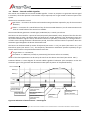
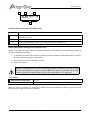
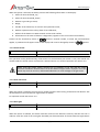
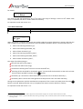
1
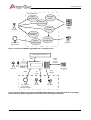
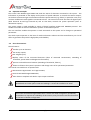
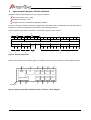
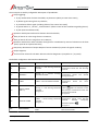
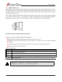
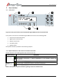
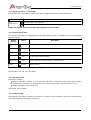
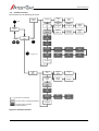
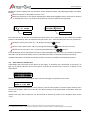
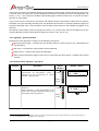
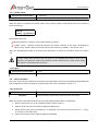
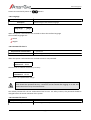
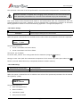
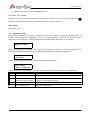
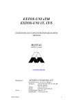
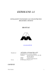
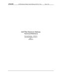
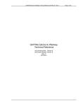
User's Manual
Control Unit Module
Sigma MOD LCD
Product Code: PW-033-B
User's Manual: POD-003-ENG R02
We design, manufacture, implement and support:
Systems for Monitoring, Detection and Reduction of gas hazards
We invite you to familiarize yourself with our offer on www.atestgaz.pl
Atest-Gaz A. M. Pachole sp. j.
ul. Spokojna 3, 44-109 Gliwice
Poland
tel.: +48 32 238 87 94
fax: +48 32 234 92 71
e-mail: [email protected]
www.atestgaz.pl
www.atestgaz.pl
1
Remarks and reservations
Connection and operation of the device is allowed only after reading and understanding the contents
of this document.
The manufacturer bears no responsibility for errors, damages and failures caused by improper
selection of devices and cable, improper installation or failure to understand the contents of this
document.
Arbitrary performing of any repairs and modifications in the device is not allowed. The manufacturer
bears no responsibility for results of such interventions.
Excessive mechanical, electrical or environmental exposure may result in damage to the device.
Use of damaged or incomplete devices is not allowed.
s. 3|42
User's Manual: POD-003-ENG R02
www.atestgaz.pl
Table of contents
1 Remarks and reservations...............................................................................................................................3
2 How to use this manual?.................................................................................................................................6
3 Preliminary information..................................................................................................................................7
3.1 Device description...................................................................................................................................7
3.2 Operation Principles................................................................................................................................9
3.3 Short characteristic.................................................................................................................................9
4 Input-output interfaces. Electric interface....................................................................................................10
4.1 Relay outputs PK 1 ÷ 8..........................................................................................................................11
4.2 Digital inputs DI 1 ÷ 4............................................................................................................................14
4.3 Communication port SBUS....................................................................................................................15
4.4 Communication port ExBUS – data „gateway”, „External DI” inputs....................................................15
4.5 Line comunication terminator and polarization...................................................................................16
5 User interface................................................................................................................................................17
5.1 Front panel............................................................................................................................................17
5.1.1 Optical indicators in the control unit module status field.................................................................17
5.1.2 Digital Inputs DI 1 ÷ 4 status field......................................................................................................18
5.1.3 Detector status field...........................................................................................................................18
5.1.4 LCD display field.................................................................................................................................18
5.1.5 Keyboard field....................................................................................................................................18
5.2 Interface structure................................................................................................................................20
5.3 Start of device, interface test................................................................................................................21
5.4 Main View.............................................................................................................................................22
5.4.1 Signalling – general principles ...........................................................................................................23
5.4.2 Detector status indication – gas alarms ............................................................................................23
5.4.3 Detector status indication – special states........................................................................................25
5.4.4 Reaction to gas...................................................................................................................................26
5.5 Buzzer – internal audible signaller........................................................................................................27
5.6 Access to options – login mechanism...................................................................................................28
5.7 Detector menu......................................................................................................................................28
5.7.1 History................................................................................................................................................29
5.7.2 Channel info.......................................................................................................................................30
5.7.3 Unlock sensor.....................................................................................................................................31
5.7.4 Auto-null sensor.................................................................................................................................31
5.7.5 Noise gate...........................................................................................................................................31
5.7.6 Alarm thresholds................................................................................................................................32
5.7.7 „Inhibit” Mode...................................................................................................................................33
5.7.8 Logout................................................................................................................................................33
5.8 Control Unit Menu................................................................................................................................33
5.8.1 Device Info .........................................................................................................................................33
5.8.2 Language............................................................................................................................................34
5.8.3 Password for level 1...........................................................................................................................34
5.8.4 Password for level 2...........................................................................................................................34
5.8.5 Buzzer settings...................................................................................................................................35
5.8.6 GTW settings......................................................................................................................................35
5.8.7 Logout................................................................................................................................................36
5.9 Operations, results................................................................................................................................36
6 System architectures.....................................................................................................................................37
7 Other information.........................................................................................................................................39
7.1 Installation.............................................................................................................................................39
s. 4|42
User's Manual: POD-003-ENG R02
www.atestgaz.pl
7.2 Start-up.................................................................................................................................................39
7.3 Utilization..............................................................................................................................................39
7.4 Markings................................................................................................................................................39
7.5 Basic technical parameters...................................................................................................................39
7.6 Dimensions............................................................................................................................................40
7.7 Configuration.........................................................................................................................................41
8 Appendices....................................................................................................................................................42
List of Tables
Table 1: Optical indicators status notation..........................................................................................................6
Table 2: Electric interface description...............................................................................................................11
Table 3: Default configuration of relay outputs................................................................................................13
Table 4: Default configuration of DI inputs.......................................................................................................14
Table 5: Default configuration of inputs External DI.........................................................................................15
Table 6: ExBUS line terminators configuration, and SBUS line polarization.....................................................16
Table 7: Description of optical indicators signalling control unit module status..............................................17
Table 8: Description of optical indicators signalling digital inputs DI status ....................................................18
Table 9: Description of optical indicators signalling detector status................................................................18
Table 10: Description of buttons.......................................................................................................................19
Table 11: Description of button combinations..................................................................................................19
Table 12: Description of screen areas in the Main View...................................................................................22
Table 13: Description of display areas in detector menu..................................................................................29
Table 14: Communication error codes..............................................................................................................36
Table 15: Comparison of Sigma Gas system architectures................................................................................37
Table 16: Basic technical parameters................................................................................................................40
List of Figures
Figure 1: Control Unit Module Sigma MOD LCD – examples of use ..................................................................8
Figure 2: Pictorial diagram of Control Unit Module Sigma MOD LCD co-operation with its surroundings (uses
exemplary, typical components of the control unit's working environment).....................................................8
Figure 3: Electric Connections...........................................................................................................................10
Figure 4: Galvanic separation between device's interfaces – block diagram..................................................10
Figure 5: Relay in activation and deactivation state.........................................................................................11
Figure 6: Optical alarm (hold-on) – principle of PK4 operation depending on changes in gas concentration. 13
Figure 7: Audible alarm – principle of PK5 operation depending on changes in gas concentration................13
Figure 8: Connection of signal to inputs DI1 and DI2........................................................................................14
Figure 9: Terminators configuration jumper after removal of SBUS and ExBUS cover.....................................16
Figure 10: Front panel of the Control Unit Module Sigma MOD LCD with functional fields............................17
Figure 11: Interface structure...........................................................................................................................20
Figure 12: Display areas in Main View..............................................................................................................22
Figure 13: Behaviour of the detector status field depending on changes to gas concentration .....................26
Figure 14: Behaviour of internal buzzer – time diagram...................................................................................27
Figure 15: Display areas after entering the menu.............................................................................................29
Figure 16: Interface during history presentation..............................................................................................30
Figure 17: Block diagram of a system without Sigma MOD DRV......................................................................38
Figure 18: Block diagram of a system with Sigma MOD DRV............................................................................38
Figure 19: Dimensions.......................................................................................................................................40
s. 5|42
User's Manual: POD-003-ENG R02
www.atestgaz.pl
2
How to use this manual?
The following notation of optical indicators status is used throughout the document:
Symbol
Interpretation
Optical indicator on
Optical indicator flashing
Optical indicator off
Optical indicator status not determined (depends on other
factors)
Table 1: Optical indicators status notation
Contents of the LCD display are marked as follows:
Example message
on screen
Important parts of the text are marked as follows:
Pay special attention to information given in those fields.
s. 6|42
User's Manual: POD-003-ENG R02
www.atestgaz.pl
3
Preliminary information
3.1
Device description
Control Unit Module Sigma MOD LCD is part of Gas Detection System Sigma Gas. The main role of this
system is to measure gas concentration in the surrounding and perform proper actions in order to prevent
and/or eliminate the hazard. This system consists of:
gas detectors – responsible for monitoring atmosphere condition in the protected area,
control units – responsible for reading the information coming from gas detectors and developing
signals necessary for e.g. alarm system control,
alarm components (audible and visual signallers) – used to warn people present in the dangerous
environment,
network equipment ΣBUS – enabling safe data exchange in the system,
associated devices, such as operator panels, data gateways, visualization panels, etc. Their purpose is
to extend the system capabilities by parametrization, advanced data presentation, integration with
other systems, etc.
Functionality of the Control Unit Module Sigma MOD LCD covers several of the above mentioned areas.
These are (see also Figure 1 and 2):
communication with gas detectors,
audible and visual signallers control (by means of contact outputs),
presentation of data regarding system conditions to other external systems (by means of digital
interface RS-485 and contact outputs),
presentation of system condition to the operator (by means of optical controls, alphanumeric display
and internal buzzer),
system operation control (by means of build-in buttons, digital inputs1 and digital interface RS-485),
parametrization and execution of operator commands.
1
bi-state
s. 7|42
User's Manual: POD-003-ENG R02
www.atestgaz.pl
Sigma MOD LCD
Get system
status
Display
System State
Perform
User Command
Control
the System
Operator
PLC,
SCADA,
Fire
Parametrise
the System
Operate
the detectors
Gas Detector
Sigma SmArt
Control
the Signallers
Signallers
Figure 1: Control Unit Module Sigma MOD LCD – examples of use
Other Sigma Gas devices
DI
inputs
Operator
RS485
relay
outputs
DI inputs
ΣBUS
Sigma MOD LCD
Display,
keyboard
ΣBUS
Gas Detector
Sigma SmArt
Monitored object
PLC, SCADA,
Fire
Relay
DI
inputs
outputs
Human
Signallers
Figure 2: Pictorial diagram of Control Unit Module Sigma MOD LCD co-operation with its surroundings
(uses exemplary, typical components of the control unit's working environment)
s. 8|42
User's Manual: POD-003-ENG R02
www.atestgaz.pl
3.2
Operation Principles
The Control Unit Module Sigma MOD LCD reads the status of detectors connected to the system. This
information is presented on the display and by means of optical indicators. It controls the contact outputs,
on the basis of measured gas concentration and other special statuses (e.g. failure). In particular cases, they
can have audible and visual signallers connected to them. The control unit reads the status of digital inputs
(both electrical DI and logic External DI) and on that basis, controls the system operation (starts or
deactivates outputs).
The system image is made available by means of digital interface RS-485 with MODBUS protocol. This
enables connection of external automation systems or visualization panels.
The user interface enables the operator to send commands to the system and to change its operational
parameters.
The whole system operates on the basis of modern electronic solutions and the manufacturer put a lot of
effort to guarantee the product's high quality and reliability.
3.3
Short characteristic
Device features:
handles up to 32 detectors,
has 8 relay outputs,
has 4 digital inputs,
displays status of the connected detectors (value of measured concentration, exceeding of
thresholds, special states and diagnostic information)
presents archived historical statuses (exceeding of thresholds, failures),
allows to influence the system's operation and change some of its operational parameters.
The control unit module can co-operate with:
Gas Detectors Sigma SmArt and Sigma ProGas,
Control Unit Module Sigma MOD DRV,
other devices compliant with built-in input-output interfaces.
The Control Unit Module Sigma MOD LCD is intended for operation in control rooms,
switchboards and other places inside the buildings. It cannot be installed in Ex zones.
The Control Unit Module Sigma MOD LCD is a device with wide configuration possibilities,
nevertheless to improve the readability of this manual, many functions have been described
on the basis of default configuration.
s. 9|42
User's Manual: POD-003-ENG R02
www.atestgaz.pl
4
Input-output interfaces. Electric interface
The device has the following electric input-output interfaces:
8 contact outputs (PK1 ÷ PK8),
4 digital inputs (DI1 ÷ DI4),
2 digital interfaces, standard RS-485 (SBUS, ExBUS).
Functions of these interfaces are widely configurable, nevertheless due to readability they are described on
the basis of a default configuration (see details in the following sections).
The description of the electric interface is presented in Figure 3 and in Table 2
1
GND
+
2
GND
+
1
2
3
Power supply
A
ExBUS
B
COM
NC
NO
DI
SBUS
GND
4
GND
3
A
B
Line
terminators
COM
COM
NC
NO
COM
NO
COM
NC
NO
PK1
PK2
PK3
PK4
PK5
PK6
PK7
PK8
NO
NC
COM
NO
NC
5
4
NC
COM
NO
NC
COM
NO
COM
NC
6
Figure 3: Electric Connections
Some of the interfaces are mutually galvanic insulated. This has been presented on a block diagram below.
5
4
Power
supply
DI
SBUS, EXBUS
3
3
3
3
3
3
PK 1
PK 2
PK 3
PK 4
PK 5
PK 6
PK 7
PK 8
3
3
3
3
ALPA ΣLCD
Figure 4: Galvanic separation between device's interfaces – block diagram
s. 10|42
User's Manual: POD-003-ENG R02
www.atestgaz.pl
No.
1
2
3
4
Name
Terminal
Supply
Description
Device supply port. Parameters – see section 7.5 .
GND
Negative supply pole. Both terminals „GND” are internally connected.
+
Positive supply pole. Both terminals „+” are internally connected.
DI
Digital inputs, see section 4.2 .
1÷4
Input terminal DI1 ÷ DI4.
COM
Common terminal of inputs DI.
SBUS
System communication port. Used for data exchange between devices in Sigma
Gas system.
A
Signal line A.
B
Signal line B.
GND
Signal ground. Internally connected with terminal „GND” of supply port.
ExBUS
Communication port, see csection 4.4 .
A
Signal line A.
B
Signal line B.
GND
Signal ground. Internally connected with terminal „GND” of supply port.
5
Line
terminators
Configuration jumpers of SBUS and ExBUS line terminators. See section 4.5 .
6
PK1 ÷ PK8
Relay outputs, see section 4.1
COM
Common terminal of relay.
NO
Normally open contact of relay.
NC
Normally closed contact of relay.
Table 2: Electric interface description
For detailed information about connections see section 6 .
4.1
Relay outputs PK 1 ÷ 8
The Control Unit Module Sigma MOD LCD is equipped with eight universal relay outputs. These outputs can
be in one of two states: activation or deactivation (the activation state means that voltage has been sent to
the relay coil). The terminals are then connected as on the diagrams below:
Deactivated
Activated
NC
NC
NO
NO
COM
COM
Figure 5: Relay in activation and deactivation state
Relay output status can be viewed by means of the user interface. See section 5.8.1 for details. Technical
parameters of outputs – see section 7.5 .
s. 11|42
User's Manual: POD-003-ENG R02
www.atestgaz.pl
These outputs are widely configurable. Description of possibilities:
relay triggering:
• by any combination of alarm thresholds, any detectors (ability to crate alarm zones),
• by failure signal coming from any detector,
• by cumulative failure signal (including failure of the control unit itself),
• by special states i.e. „service”, „measurement” (allows control of the cumulative signalling device)
• by the input DI and External DI,
operation with hysteresis based on detector alarm thresholds,
delay of switch on in the range from 1s to 100 min.,
delay of switch off in the range from 1s to 100 min.,
operation with hold-on after excitation decay (hold-on cancellation by means of a button on the front
panel, inputs DI or inputs External DI),
temporary deactivation of output despite of active excitation (by means of signals as above),
output negation,
control of the valve with coil 230 V without valve line diagnostics (3 impulses 1s / 1s pause).
The default configuration has been described below:
Output No.
Function
Output activation2
Output deactivation
PK1
WARNING 1
Decrease of the measured gas
Warning 1 – first warning threshold
concentration below the first warning
exceeded.
threshold.
PK2
WARNING 2
Warning 2 – second
threshold exceeded.
PK3
ALARM
ALARM – alarm threshold exceeded.
OPTICAL ALARM
(hold-on)
Hold-on alarm cancellation signal
Warning 1 – first warning threshold (button
) after the decrease of the
exceeded.
measured gas concentration below the
See Figure 6.
first warning threshold.
See Figure 6.
PK4
PK5
ACOUSTIC ALARM
warning
Decrease of the measured gas
concentration below the second
warning threshold.
Decrease of
concentration
threshold.
the measured gas
below
the
alarm
Decrease of the measured gas
ALARM – third warning threshold concentration below third warning
threshold.
Possible
temporary
exceeded.
See Figure 7.
deactivation (button
).
See Figure 7.
PK6
2
MEASUREMENT
At least one sensor in measurement None of the sensors
mode.
measurement mode.
is
in
the
See Figure 5.
s. 12|42
User's Manual: POD-003-ENG R02
www.atestgaz.pl
None of the sensors is in the SERVICE
mode
PK7
SERVICE
At least one sensor in SERVICE mode.
PK8
FAILURE
At least one device in the system is
None of the devices is in the FAILURE
signalling the failure status or the
status.
control unit is without supply.
Table 3: Default configuration of relay outputs
Configuration of outputs PK1 ÷ PK8 should be determined at the order stage (outputs are
configured by the manufacturer in the production process).
Gas
Concentration
Warning_1
Key
Relay PK4
time
Warning_1 Relay activation
Warning decline, but
the Relay is latched
Operator request
rejected - Warning_1
still active
Operator press the key
– Relay deactivate
Figure 6: Optical alarm (hold-on) – principle of PK4 operation depending on changes in gas concentration
Gas
Concentration
ALARM
Key
Relay PK5
time
Alarm has appeared
- PK5 activation
Operator press the Key,
PK5 deactivates despite
the active Alarm
Alarm has disappeared,
-PK 5 deactivation
t1 > tD
Deactivation time
elapsed
- PK5 reactivates.
deactivation
time
Figure 7: Audible alarm – principle of PK5 operation depending on changes in gas concentration
s. 13|42
User's Manual: POD-003-ENG R02
www.atestgaz.pl
4.2
Digital inputs DI 1 ÷ 4
These inputs are used to influence the operation of the system by means of external signals such as other
automation systems, alarm systems or buttons. Depending on signal supplied to the input (see section 7.5
), these inputs can be in two states. Actual state of these inputs can be viewed by means of the user
interface (see section 5.1.2 ).
These inputs are galvanically insulated from the rest of device circuits, but not from each other (see Figure
4). In order to use the inputs, it is necessary to connect the voltage of any polarity between terminals
appropriate for the input „1”÷„4” and the terminal „COM”. This has been shown in Figure 8 below.
1
2
U1
3
U2
4
COM
Figure 8: Connection of signal to inputs DI1 and DI2
Inputs DI 1 to DI 4 are widely configurable. They allow to:
temporarily mute (deactivate) the internal buzzer (see section 5.1.2 ),
temporarily switch off (deactivate) any relay output (in particular cases mute external audible
signaller),
unlock any output in hold-on status (in particular cases cancel the hold-on, optical alarm),
enforce switch on of any relay output.
Default configuration:
Input No.
Function
DI 1
Internal buzzer deactivation
DI 2
External audible signaller deactivation
DI 3
Hold-on optical alarm cancellation
DI 4
Alarm enforcement
Table 4: Default configuration of DI inputs.
Configuration of inputs DI1 ÷ DI4 should be determined at the order stage (inputs are
configured by the manufacturer in the production process).
s. 14|42
User's Manual: POD-003-ENG R02
www.atestgaz.pl
4.3
Communication port SBUS
This port is used for information exchange between devices of the Sigma Gas system. This is a digital port
operating on the basis of RS-485 and ΣBUS3 protocol.
The port is equipped with line terminators that can be configured in numerous ways. See chapter 4.5 for
details.
4.4
Communication port ExBUS – data „gateway”, „External DI” inputs
The Control Unit Module Sigma MOD LCD is equipped with communication port called ExBUS, which is used
for data exchange between Sigma Gas system and external environment (e.g. PLC, SCADA, etc.). The port is
bi-directional and it can be used to read the following information about actual status of Sigma Gas system:
detectors' statuses,
values of measured concentrations,
PK outputs and DI inputs state
It is also possible to influence the system operation by means of binary inputs. The scope of their
application is the same as for DI inputs – see section 4.2 .
By means of this port it is also possible to perform operator commands (such as cancelling the sensor's
lock). Details – see appendix (section 8 ).
Data exchange is performed on the basis of digital interface RS-485 and protocol MODBUS, and the control
unit module is a device of SLAVE type. The above mentioned functionalities are performed by readout and
saving of registers from the „holding registers” area of device. The following are the possible operating
parameters of the interface:
communication protocol MODBUS ASCII / MODBUS RTU;
network address of device in the range 1÷ 255;
transmission speed: 4800, 9600, 19200, 38400, 57600 and 115200 b/s;
parity control method: (N) no control, (E) even, (O) odd;
for the MODBUS ASCII protocol – format of frame: 7 and 8 data bits.
Values of the above parameters can be set by the user from menu level of the device (see section 5.8.6 ).
Memory map of device – see appendix (section 8 ).
Default configuration of inputs External DI is provided in table below:
Bit
Flag
Description
Default configuration
0
External_DI_0
Input No. 0
Internal buzzer deactivation
1
External_DI_1
Input No. 1
External audible signaller deactivation
2
External_DI_2
Input No. 2
Hold-on optical alarm cancellation
3
External_DI_3
Input No. 3
Alarm enforcement
4..15
External_DI_4..15
Input No. 4..15
Not assigned
Table 5: Default configuration of inputs External DI
3 Σ – stands for „sigma”.
s. 15|42
User's Manual: POD-003-ENG R02
www.atestgaz.pl
All settings of this port's functionality should be determined at the order stage (this applies
to the type of protocol and assignment of External DI inputs to appropriate functions).
The port is equipped with line terminators that can be configured in various ways. See section 4.5 for
details.
4.5
Line comunication terminator and polarization
SBUS communication port is equipped with line polarization circuit and ExBus communication port is
equipped with line terminator. To configure their operation, carefully remove the cover of ports SBUS,
ExBUS and put valves in uncovered terminal:
JP1
JP2
JP3
JP4
Configuration jumpers
One of the ExBUS pin
Figure 9: Terminators configuration jumper after removal of SBUS and ExBUS cover
The settings are presented in the table below:
Jumper
positions
JP1
Operation
Electrical diagram
Terminator of port ExBUS disconnected
A
B
JP1
Terminator of port ExBUS connected
A
120Ω
B
JP2
Polarization of port SBUS disconnected
A
JP3
JP4
B
Polarization of SBUS connected
+5V
8,2kΩ
JP2
A
JP3
8,2kΩ
JP4
B
8,2kΩ
Table 6: ExBUS line terminators configuration, and SBUS line polarization
s. 16|42
User's Manual: POD-003-ENG R02
www.atestgaz.pl
5
User interface
5.1
Front panel
3
4
5
C12 H2 pomp
12.6 %LEL _▄█__
2
1
Figure 10: Front panel of the Control Unit Module Sigma MOD LCD with functional fields
Front panel of the Control Unit Module Sigma MOD LCD consists of the following fields:
1. Control unit module status field,
2. Digital inputs DI status field,
3. Detector status field,
4. LCD display field,
5. Keyboard field.
Description of fields is provided in the following chapters.
5.1.1 Optical indicators in the control unit module status field
Optical indicators in this field signalize status of the control unit.
Optical indicator
OPERATION
(green colour)
Description
Permanent light – proper operation of device.
Even flashing _∏_∏_∏_∏_ – device configuration is not complete. Contact the
manufacturer.
One flash every 2s _∏________ – device during configuration.
FAILURE
(yellow colour)
Permanent light – critical failure of device, contact the manufacturer.
Even flashing_∏_∏_∏_∏_ – non-critical failure of device, contact the manufacturer.
Table 7: Description of optical indicators signalling control unit module status
s. 17|42
User's Manual: POD-003-ENG R02
www.atestgaz.pl
5.1.2 Digital Inputs DI 1 ÷ 4 status field
Optical indicators in this field are used to view status of digital inputs DI 1 ÷ 4 (see section 4.2 ).
Optical indicator
Description
1÷4
(green colour)
Permanent light – active DI input
Switched off – non-active DI input
Table 8: Description of optical indicators signalling digital inputs DI status
5.1.3 Detector status field
On the front panel there is a signalling field showing detector's status. This field consists of the following
optical indicators:
Optical
indicator
Colour
Description
- red
Gas overload
ALARM
- red
Alarm threshold exceeded
2
- red
Second warning threshold exceeded
1
- red
First warning threshold exceeded
Measurement
- green
Detector operates normally (detector's operating status)
Failure
- yellow
Detector's failure
Table 9: Description of optical indicators signalling detector status
See sections 5.4.2 and 5.4.3 for details.
5.1.4 LCD display field
The display is used to:
present operation statuses of the connected detectors, measured concentration and auxiliary
information in relation to the detectors (name of measurement point, concentration unit, etc.),
display messages, menu presentation.
See section 5.2 for details.
5.1.5 Keyboard field
The keyboard of this device consists of 6 buttons. It is used to enter information by the user and influence
the system operation. Description of buttons:
s. 18|42
User's Manual: POD-003-ENG R02
www.atestgaz.pl
Button
Alternative
function4
Description
Scroll left – used to change the currently displayed channel.
Scroll right – used to change the currently displayed channel.
Scroll up – used to navigate within device's menu and for parameter value setting.
Alternatively – to temporarily mute (deactivate) the external audible signaller.
Scroll down – used to navigate within device's menu and for parameter value setting.
Alternatively – to cancel the hold-on alarm.
ESC
Cancel – used to navigate within device's menu (coming out of menu and options) and
abandon the performed operation.
Alternatively – to temporarily mute (deactivate) the internal buzzer.
OK
Confirm – used to navigate within device's menu (option selection) and to confirm
operations and entered values.
Table 10: Description of buttons
Combination of buttons:
Combination of buttons
Pressed simultaneously
Description
Start-up of interface test – see section 5.3 . Available only in Main View (see section 5.4
).
Table 11: Description of button combinations
4
Alternative function is available only in Main View (see section 5.4 ).
s. 19|42
User's Manual: POD-003-ENG R02
www.atestgaz.pl
5.2
Interface structure
The interface has the following structure:
Detector
Menu
1.History
View of
the
history
Clear
All?
2.Chann
el
info
Up
threshold
s
Down
threshold
s
Type,
range
3.Unlock
sensor
Address,
Serial no
Worktime,
CAL date
Substan
ce,
CAS no
6.Alarm
threshold
s
W1 UP
W2 UP
Alarm
UP
7.Inhibit
Mode
Alarm
Down
W2
Down
W1
Down
1.Device
Info
Firmwar
e,
Serial
Adresse
s
2.Langu
age
Device
Status
Outputs
React.
time
for Alarm
React
time
for
Failures
Start
Interface
Test
together
Main
View
Short
OK
OK
Long (>1 s)
4.Autonull
Sensor
5.Noise
Gate
8.Logout
Control
Unit
Menu
3.Passw
ord
Level 1
4.Passw
ord,
Level 2
5.Buzzer
Settings
Function non protected
Function Level 1 protected („Operating”)
6.Logout
Function Level 2 protected
(„Parametrization”)
Figure 11: Interface structure
s. 20|42
User's Manual: POD-003-ENG R02
www.atestgaz.pl
Keyboard is used to operate the user interface. Unless otherwise stated, the following principles are always
binding:
buttons function as described in section 5.1.5 ,
flashing inscriptions on the display (excluding the Main View) highlight places, where user's decision
is required (this can be e.g. values to be entered or consent to perform the operation).
Noise gate level
0.0 % of range
Save Changes?
Yes(OK),No(ESC)
Value to input
Request for decision
The main view of the interface is the Main View (see section 5.4 ). After start-up the control unit module
presents it immediately after the interface test (see section 5.3 ). From the Main View user can proceed to:
detector's menu (see section 5.7 ), by briefly pressing the
OK
device's menu (see section 5.8 ), by pressing and holding the
button,
OK
interface test (see section 5.3 ), by pressing simultaneously the
button for over 1 second,
buttons.
From all selected menus and options that do not require dialogue with user, or are not related to operation
execution, the device automatically returns to the Main View after 10 seconds of keyboard inactivity.
A detailed description of all elements of the interface structure is provided in the following sections.
5.3
Start of device, interface test
Immediately after connection of the device to the supply, an interface test is performed. Its purpose is to
light up all optical indicators on the front panel, activate the internal buzzer5 and turn all points of LCD
screen black:
████████████████
████████████████
After 2 seconds the test is interrupted and a welcome message is presented on the screen:
Atest – Gaz
ALPA Σ LCD RXX
The message includs manufacturer’s name, device's name and the product's current revision number6 (XX is
the revision number). After next 2 seconds, the device switches to the presentation of the Main View (see
section 5.4 ).
Interface test (the above sequence) can be initiated on demand by means of the keyboard (see section
5.1.5 ).
5
6
The signal may not be heard if the device is configured to work without an internal buzzer (see section 5.5)
Product revision number – is the identifier of the product release, it includes hardware, installed software and documentation.
s. 21|42
User's Manual: POD-003-ENG R02
www.atestgaz.pl
It is recommended to perform this test once per week and observe if during the test all
controls, display and buzzer are operating correctly.
5.4
Main View
The Main View can be divided into several areas:
1
2
3
C12 H2 pomp HIS
12.6 %LEL _▄█__L
4
5
6
7
8
Figure 12: Display areas in Main View
Area No.
Description
1
Number of the currently displayed channel (1 ÷ 32).
2
Description of detector's location.
3
Special markers. In this area flashing messages can occur:
• HIS – information, that there has been at least one event registered in the device history (see
section 5.7.1 ),
• B – internal buzzer is active and it can be cancelled by means of a keyboard button (see section
5.1.5 ),
• S – audible alarm is active and it can be temporarily deactivated by means of a keyboard button (see
section 5.1.5 )
• A – hold-on alarm is active and it can be cancelled by means of a keyboard button (see section 5.1.5
).
Attention! Messages „B”, „S”, „A” may not appear on the display. This depends on the configuration of
the device.
4
Value of concentration measured by the detector on the current channel.
5
Concentration unit.
6
Trends area. Chart showing concentration registered by a detector for about 1 minute is displayed in
this area. The bar on the right shows the latest indication, and the bar on the left - the oldest.
7
Information on logging. Possible messages:
• If this area (last character in the second line on display) is empty, it means that the lowest level of
authorization is in force.
• Character „L” displayed alternately with digits 1 ÷ 2 means that the user is logged into a higher level
of authorization – relevant to the displayed digit. See details in section 5.6 .
8
In some situations areas 4, 5, 6 can be connected and used to display messages about special
conditions of the detector or system. Details later in this section.
Table 12: Description of screen areas in the Main View
s. 22|42
User's Manual: POD-003-ENG R02
www.atestgaz.pl
In this view, the control unit module displays cyclic statuses of all channels. Channel switching occurs every
3 seconds. Users can switch the currently displayed channel (this is possible by means of the keyboard, see
section 5.1.5 ) - the control unit module stops displaying the selected channel for 15 seconds and then
switches to cyclic display.
If any of the sensors connected to the device will indicate the gas concentration above the first warning
threshold, the cyclic switching will take place only between the channels on which the detector appears in
the above described status. In this situation, manual switch of the channel is still available and applies to all
channels.
The detector status field on the front panel (see section 5.1 ), presents the state of the detector from the
currently displayed channel (description of signals in sections 5.4.2 and 5.4.3 ).
5.4.1 Signalling – general principles
The detector status indication is subject to the following convention:
green permanent light – indicates that the device performs its basic function (e.g. measurement of
concentration),
red colour – indicates that a gas hazard has been detected,
yellow colour – indicates any failures and damages,
other colours and flashing signals, which are not covered by the above points – indicate other special
statuses.
5.4.2 Detector status indication – gas alarms
Situation
No hazard
Description
Optical
indicators
Detector
operates
properly,
performs
measurement of concentration, which is
confirmed by the permanently lit optical
indicator „Measurement”.
ALARM
2
Display7 / buzzer
C12 H2 pomp
0.5 %LEL _____
1
Measur.
Failure
Warning 1
Gas concentration is above the first warning
threshold.
Optical indicator „1” lights permanently on the
panel, internal buzzer is activated, which can be
cancelled by means of keyboard.
ALARM
2
C12 H2 pomp
11.2 %LEL _____
1
Measur.
Failure
7
Display description contains an exemplary content. It has been assumed that the alarm thresholds have been set in the following manner:
warn. 1 – 10% DGW, warn. 2 – 15% DGW, alarm – 20% DGW.
s. 23|42
User's Manual: POD-003-ENG R02
www.atestgaz.pl
Situation
Warning 2
Description
Optical
indicators
Gas concentration is above the second warning
threshold.
Optical indicators „1” and „2” light permanently
on the panel, internal buzzer is activated, which
can be cancelled by means of keyboard.
ALARM
2
Display / buzzer
C12 H2 pomp
17.9 %LEL ____▄
1
Measur.
Failure
Alarm
Gas concentration is above the alarm threshold.
Optical indicators „1” and „2” and „ALARM” light
permanently on the panel, internal buzzer is
activated, which can be cancelled by means of
keyboard.
ALARM
2
C12 H2 pomp
29.3 %LEL ___▄█
1
Measur.
Failure
Overload
Lock8
8
Gas concentration is above the overload value.
Optical indicators „1”, „2”, „ALARM” and „ ”.
light permanently on the panel. Gas detector
continues measurement, which is confirmed by
the
permanently
lit
optical
indicator
„Measurement”.
A message about overload appears on the
display.
Gas concentration is above overload value.
Optical indicators „1”, „2”, and „ALARM” light
permanently on the panel. The optical indicator
„ ” flashes evenly ( _∏_∏_∏_∏_). The
detector is in the lock mode – last concentration
value has been latched. The detector does not
perform any measurements – optical indicator
„Measurement” is off. Message „Lock” appears
on the display.
ALARM
2
C12 H2 pomp
126.7%LEL OVLD
1
Measur.
Failure
ALARM
2
C12 H2 pomp
126.7%LEL LOCK
1
Measur.
Failure
This status appears only in detectors with locking mechanism.
s. 24|42
User's Manual: POD-003-ENG R02
www.atestgaz.pl
5.4.3 Detector status indication – special states
Situation
Warming up
Calibration
Test
Non-critical
Failure
Description
Optical
indicators
Gas detector is preparing to work. Its
indications are temporarily ignored.
Optical indicators light up in sequence from
bottom to top.
Optical indicators activate in sequence from
bottom to top.
Message “Warming up” appears on the
display.
Gas detector is in calibration mode.
Its indications are temporarily ignored.
Optical indicator „Measure” flashes once
every 2 seconds ( _∏_______). Other
optical indicators are off.
Message „Calibration” appears on the
display.
Gas detector is in the test mode. Its
indications are simulated but all signals are
treated as real. „Alarms” or „Failures” can
be simulated. Optical indicator „Measure” flashes
twice
every
2
seconds
(_∏_∏_____).
Message „Test” appears on the display.
Minor failure of the detector threatening its
measurement accuracy (i.e.: exceeded time
to next calibration).
Detector continues measurements. Optical
indicator
“Failure”
flashes
evenly
(_∏_∏_∏_∏_).
ALARM
2
Display9 / buzzer
C12 H2 pomp
Warming up...
1
Measure
Fail
ALARM
2
C12 H2 pomp
Calibration
1
Measure
Fail
ALARM
2
C12 H2 pomp
17.9 %LEL Test
1
Measure
Fail
ALARM
2
C12 H2 pomp
29.3 %LEL___▄▄
1
Measure
Fail
Critical Failure
Detector is damaged and stopped
measuring.
Optical indicator “Failure” is permanently lit
and other optical indicators are off.
Message with the error code (Fail:XXXXH)
appears on the display.
Internal buzzer is activated.
Short break in Short break in communication with the
communication detector. Previous detector state remains
valid, but optical indicator „Measure” is off.
ALARM
2
C12 H2 pomp
Fail:0110H
1
Measure
Fail
ALARM
2
C12 H2 pomp
29.3 %LEL ___▄▄
1
Measure
Fail
9
Exemplary messages
s. 25|42
User's Manual: POD-003-ENG R02
www.atestgaz.pl
5.4.4 Reaction to gas
Correct operation of the detector is indicated by a green light. If dangerous gas will appear in the detector's
surrounding and its concentration exceeds first, second warning threshold or the alarm threshold, optical
indicators relevant to the threshold will light up in the detector status field (see section 5.1.3 ) - controls
marked as „1”, „2” or „ALARM”. At the same time, the internal buzzer is activated, which can be cancelled
by means of keyboard (see section 5.1.5 ).
If the gas concentration will exceed the overload threshold value, then:
for detectors with catalytic sensors – the sensor will be locked (sensor is switched off, detector locks
the last performed measurement). Lock state is displayed in the detector status field, (see section
5.4.2 ). In order to return the detector to its normal operation, the „unlock lock” operation must be
performed using the options menu (see section 5.7.3 ) or other device connected to the system.
for detectors with other sensors – in the detector status filed the optical indicator marked „ ” lights
up. The detector is still in operation and performs concentration measurements, which is confirmed
by the optical indicator „Measurement”.
The following Figure shows the behaviour of the interface in response to exemplary changes of gas
concentration, registered by the detector.
Gas
Concentration
„Unlock sensor”
operation
Overload
ALARM
Warning_2
Sn02, PID
time
ALARM
2
1
Measure
ALARM
2
1
Gas concentration drops,
warnings and alaerm too.
Locked. Sensor is
switched off, and the last
valid measurement is
lached.
Warm up
Alarm
Warning 2
Warning 1
Warning 2
Gas
overload
Warning 1
No gas hazard
Desription
Warning 1
Measure
No gas hazard
Catalityc sensor
elektrochemical, IR
Warning_1
Figure 13: Behaviour of the detector status field depending on changes to gas concentration
s. 26|42
User's Manual: POD-003-ENG R02
www.atestgaz.pl
5.5
Buzzer – internal audible signaller
The control unit module has an internal audible signaller - buzzer. Its purpose is to generate acoustic signal
in situations, when the operator's intervention may be required, such as gas hazard or failure of part of the
system.
The buzzer is activated in case of:
gas alarms – occurrence of the first and second warning and alarm reported by any of the connected
detectors,
failure – occurrence of a critical failure of any of the connected detectors, loss of communication with
them or critical failure of the control unit module.
The activated buzzer generates a sound signal, modulated, 0,5 s sound, 0,5 s silence.
The buzzer can be muted for a period of time (temporarily deactivated). Then, despite of the fact that the
excitation signal is active, the buzzer does not generate any sound. However, if the deactivation time runs
out and the excitation signal is active, the buzzer resumes its operation (re-activates). If a new gas alarm 10
or failure occurs during the buzzer's deactivation period, the buzzer will also resume its operation. Once the
excitation signal disappears the buzzer deactivates itself.
The buzzer can be deactivated by means of keyboard (see section 5.1.5 ), DI inputs (see section 4.2 ) and
External DI inputs (see section 4.4 ). The temporary deactivation mechanism operates separately for gas
alarms and for failures. The possible deactivation times are:
for gas alarms: 1 ÷ 90 minutes,
for failures: 1 ÷ 168 hours (1 week) or permanently (the buzzer will not re-activate).
Values of the above parameters can be set by the user from the device menu level (see section 5.8.5 ).
Presented below is a time diagram of internal audible signaller's behaviour (the assumption is that the
excitation signal is the gas alarm and deactivation takes place by means of a keyboard button):
Gas concetration
Warning 2
Warning 1
Key
Buzzer
time
Hazard detected Buzzer activates
Hazard declines buzzer deactivates
Operator stroke the key,
buzzer temporally
deactivates
New Warning, buzzer
reactivates
Operator stroke the key,
buzzer temporally
deactivates
t1 > tD
deactivation period
has elapsed,
buzzer reactivates
deactivation
period
Figure 14: Behaviour of internal buzzer – time diagram
10 A new gas alarm occurs when the higher alarm threshold is exceeded on the considered sensor or threshold is exceeded in another detector.
s. 27|42
User's Manual: POD-003-ENG R02
www.atestgaz.pl
The buzzer can also be configured in such a way, that it will not activate itself at all.
5.6
Access to options – login mechanism
The control unit module has options that can significantly affect the performance of the Sigma Gas system
and the safety level. Therefore, appropriate access limitations have been implemented. The following
authorisation levels have been introduced:
level 0 – basic – enables browsing indications and additional information about the system,
level 1 – operational, password protected – enables performing maintenance activities such as sensor
unlock,
level 2 – parametrization, password protected – enables changing system parameters.
Level 0 is the default authorization level. Any user who has access to the control unit module interface will
be working with this particular level. If the user tries to select an option that requires a higher authorisation
level, the device will prompt for the access password.
Enter password
(level 1):0***
A password consists of 4 digits. Due to safety reasons, only one digit is visible. Its value can be changed with
buttons, and the digit is selected with
buttons.
Once a correct password is entered, the user is logged into the appropriate authorisation level and obtains
access to the selected option. Information about the obtained authorization level can be found in the Main
View (see section 5.4 ). Return to the basic authorization level (level 0) takes place, when:
the user selects the menu option „Log out” (see section 5.7.8 ),
keyboard is not used for 1 minute.
If the user enters incorrect password three times in a row, logging will be blocked for 5 minutes and any
attempt to access option requiring higher authorisation level will bring the following message:
Login locked
Wait X min
where X is the number of minutes to unlock.
5.7
Detector menu
Detector menu can be activated by briefly pressing the
options related to detector operation.
OK
button on the keyboard. The menu covers
Once the menu is entered, the display presents the following information (see Figure 15 below)
s. 28|42
User's Manual: POD-003-ENG R02
www.atestgaz.pl
1
2
3
C12 Sen.menu 1/8
History
4
Figure 15: Display areas after entering the menu
Area No.
Description
1
Channel number to which the option applies. This field is optional, it appears, if the option applies to
the a specific channel.
2
Menu name.
3
Currently selected option number / total number of options in a specific menu.
4
Description of the currently selected option.
Table 13: Description of display areas in detector menu
Options in the detector menu affect the working parameters of the detector. The operating procedure of
the menu should look as follows:
1. in the Main View select the channel, for which an activity should be performed (when the menu is
entered, channel selection is not possible),
2. enter the channel menu and select an option,
3. activate the option.
Options in the detector menu affect its working parameters. Therefore, one need to make
sure that the appropriate channel is selected before this option is activated. The channel
number is presented in the left upper corner of the display (field no. 1 in Figure 15).
5.7.1 History
Required level of authorization
Description
0 – basic
Enables browsing the historical events and their deletion.
When this option is selected, the control unit module presents stored historical events. At given time the
device presents events only from one detector:
s. 29|42
User's Manual: POD-003-ENG R02
www.atestgaz.pl
Channel number and location for which
historical data is presented
ALARM
2
1
K3 Reactor
<- History
Measure
Fail
Figure 16: Interface during history presentation
The channel number and location of the detector are displayed in the upper line (see section 5.4 ) and
historical events are presented by means of a detector status field (see section 5.1.3 ). As the presented
states don't reflect the current situation, the optical indicator „Measurement” is always off.
The stored historical states are:
gas alarms: exceeding 1st and 2nd warning threshold and the alarm threshold,
non-critical failure and critical failure of the detector.
The currently displayed channel can be changed by means of
buttons, but the channel change
takes place only between channels for which an event has been stored. If during selection of this option a
channel without stored events is selected, the following message will be displayed:
C2 H2 pomp
History empty
Should this occur, the channel needs to be changed (as per the above description).
Memory of historical events can be deleted. This can be achieved by means of pressing the
OK
button
while browsing the history. User will be asked to confirm the selection by means of pressing the
button.
Clear All?
(key < )
If the history is empty, the following message will appear on the screen:
History empty.
5.7.2 Channel info
Required level of authorization
Description
0 – basic
Enables browsing the additional information about the detector
s. 30|42
User's Manual: POD-003-ENG R02
www.atestgaz.pl
When this option is selected, the device presents the following information on the display:
1. Values of alarm threshold „up”;
2. Values of alarm threshold „down”;
3. Detector type and type name;
4. Range;
5. CAS No. of the substance, its common and systematic name;
6. Detector operation time in days; date of last calibration;
7. Address of the detector in ΣBUS network and its serial number.
8. Information on the state of detector's diagnostics (registers of non-critical and critical failure).
Screens can be switched by means of
buttons. Channel number, to which the presented data
applies, is presented in left upper corner of the display and it can be changed by means of
buttons.
5.7.3 Unlock sensor
Required level of authorization
Description
1 – operational
Enables cancelling the sensor lock.
This operation can be performed only, if the sensor is in the lock status (see section 5.4.4 ). The control unit
module sends the unlock sensor command to a selected sensor. For results of operation see section 5.9 .
Before using this option, please read the list of conditions to be met and the unlock
procedure included in documentation of the Gas Detector Sigma SmArt. Improper use of this
option may result in incorrect, understated indications or cause damage to the gas sensor.
5.7.4 Auto-null sensor
Required level of authorization
Description
2 – parametrization
Enables auto-zeroing operation on the detector
When this option is selected, the control unit module sends the auto-zeroing command to the detector. See
documentation of the Gas Detector Sigma SmArt for details.
For operation results see section 5.9 .
5.7.5 Noise gate
Required level of authorization
Description
2 – parametrization
Enables setting values of the detector noise gate threshold
When this option is selected, the device reads the content of the detector's memory and then the user is
asked to enter the value of the noise gate threshold (see documentation of the Gas Detector Sigma SmArt
s. 31|42
User's Manual: POD-003-ENG R02
www.atestgaz.pl
for details):
Noise gate:
0.0 % Range
The value of noise gate threshold is set in % of range. The range of settings is from 0 to 5%. When value
entry is completed, the data is saved in detector's memory.
For operation results see section 5.9 .
5.7.6 Alarm thresholds
Required level of authorization
Description
2 – parametrization
Enables to set values of the detector alarm thresholds
Par.: W1 (up)
123 ppm
When this option is selected, the control unit module reads the content of detector's memory and then the
user is asked to enter values of the detector alarm thresholds (examples above). Consecutively these are:
1. Value of 1st warning threshold „up”,
2. Value of 2nd warning threshold „up”,
3. Value of alarm threshold „up”,
4. Value of 1st warning threshold „down”,
5. Value of 2nd warning threshold „down”,
6. Value of alarm threshold „down”,
The range of possible settings is:
not less than 10% of the range11;
not more than 95% of the range;
for detectors working with %LEL unit not more than 60 %LEL;
switching off the threshold for thresholds „down” (to switch off the threshold, set the value to lower
than the lowest possible by means of the
button);
threshold „up” cannot have value lower than the previous one in the alarms hierarchy12;
threshold „down” cannot have value greater than the previous one in the alarm hierarchy;
Change to next parameter (and the simultaneous acceptance of the current one) takes place when the
button is pressed. When parameter entry is completed, the data is saved in detector's memory.
OK
For operation results see section 5.9 .
11 Attention! Settings of thresholds are made in physical unit and limitations are given in % of scope. Numerical values can differ.
12 Alarms hierarchy: thresholds „up” (from the lowest one): warning 1, warning 2, alarm; thresholds „down” (from the lowest one): warning 1,
warning 2, alarm.
s. 32|42
User's Manual: POD-003-ENG R02
www.atestgaz.pl
5.7.7 „Inhibit” Mode
Required level of authorization
Description
1 – operational
Enables to activate / deactivate „Inhibit” mode of the sensor
When this option is selected, the current status of the „Inhibit” mode is read and then the user is asked to
enter the settings:
Status:
Normal Operation
The possible values are:
Normal operation – detector in this mode operates normally,
„Inhibit” mode – detector is disconnected from the system. Detector in this state is presented by
means of the „Inhibit” signal on the front panel of the control unit module – see section 5.4.3 .
When the implemented change is confirmed, this information is saved. For operation results see section
5.9 .
„Inhibit” mode does not mean that the sensor is not supplied with power. It must not be
opened in the explosion hazard zone without previous disconnection of the power supply.
See detector's documentation for details.
5.7.8 Logout
Required level of authorization
Description
5.8
0 – basic
Enables logout (setting of basic authorization level). See section 5.6 .
Control Unit Menu
This menu covers options related to the operation and parameters of Control Unit Module Sigma MOD LCD
and the Sigma Gas system. Description of the display in this view is provided in section 5.7 .
5.8.1 Device Info
Required level of authorization
Description
0 – basic
Enables browsing the information about the control unit module
When this option is selected, the device presents the following information on the display:
1. Revision and version no. of the installed software; device serial no.;
2. Address of the control unit module on SBUS and ExBUS port;
3. Supply state of the relays (the output no. is displayed in the upper line and the status: 1 – active,
0 – inactive, in the lower line);
4. Status of the device (status registers STATEA and STATEB).
s. 33|42
User's Manual: POD-003-ENG R02
www.atestgaz.pl
Screens are switched by means of
buttons.
5.8.2 Language
Required level of authorization
Description
0 – basic
Enables change of the interface language.
Language - jezyk
When this option is selected the user is asked to select the interface language.
The available languages are:
Polish
English
5.8.3 Password for level 1
Required level of authorization
Description
1 – operational
Enables change of access password for the 1st authorization level.
When this option is selected the user is asked to enter a new password.
Enter new
password: 0***
Then the user is asked to confirm it by re-entry:
Re-enter new
password: 0***
and confirm the implemented change.
Particular attention is required when changing access password for the 1st authorization
level. Should this password be lost, a new one can be entered after logging on to the 2nd
authorization level or by the manufacturer.
The default password for the 1st authorisation level is 1111. For safety reasons, this password should be
changed before the actual utilization of the system.
5.8.4 Password for level 2
Required level of authorization
Description
2 – parametrization
Enables change of access password for the 2nd authorization level.
s. 34|42
User's Manual: POD-003-ENG R02
www.atestgaz.pl
This operation is the same as the one performed for 1st authorisation level password – see section 5.8.3 .
Particular attention is required when changing access password for the 2nd authorization
level. Should this password be lost, a new one can be entered only by the manufacturer.
Due to the nature of the functions that require a 2nd authorisation level, the manufacturer does not
provide password to this level. However, it can be obtained after consenting to conditions of Password
Sharing Agreement. Details in the Password Sharing Agreement - see appendix (chapter 8 ).
5.8.5 Buzzer settings
Required level of authorization
Description
2 – parametrization
Enables change of settings of the internal buzzer
When this option is selected the user is asked to enter values of the time parameters for buzzer's operation.
React.time for
alarm: 5 min
Consecutively these are:
1.
buzzer reactivation time for the alarm,
2.
buzzer reactivation time for the failure.
See section 5.5 for details.
To set the value „infinite” set a value greater than the maximum (using the
button).
Change to next value (and the simultaneous acceptance of the current one) takes place when the
button is pressed. When value entry is completed, the data is saved in memory.
OK
5.8.6 GTW settings
Required level of authorization
Description
2 – parametrization
Enables change of operational parameters of the built-in GTW
When this option is selected the user is asked to enter values of the operational parameters for the internal
data “gateway” (GTW).
Protokol
MODBUS ASCII
Consecutively these are:
1. Data exchange protocol.
2. Network address.
3. Transmission speed.
4. Parity control method.
s. 35|42
User's Manual: POD-003-ENG R02
www.atestgaz.pl
5. Frame format (only for protocol MODBUS ASCII).
See section 4.4 for details.
Change to next value (and the simultaneous acceptance of the current one) takes place when the
button is pressed. When value entry is completed, the data is saved in memory.
OK
5.8.7 Logout
See section 5.7.8 .
5.9
Operations, results
Some options available in the menu require the control unit module to perform operations such as:
readout, saving detectors' configuration memory or giving detectors commands to perform certain
operations. In such situations, messages like the one presented below will appear on the display:
Reading data
...
When the operation is completed, the control unit presents its result. For successful operations, the
following message is displayed (content of the upper line depends on performed operation):
Noise gate
- success
However, if any irregularity appears, an error message will be displayed:
Noise gate
- fail (code X)
where X is the error code. Possible error codes and their descriptions can be found in the table below:
Code
Description
What to do?
1
Internal device error
Contact the manufacturer.
2
Waiting time for access to the Bus ΣBUS is occupied by another device. Try again. If the problem
ΣBUS bus has been exceeded. continues – contact the manufacturer.
3
Detector did not respond
There is no communication with the detector. Check the connection.
4
Internal detector error
Contact the manufacturer.
Table 14: Communication error codes
s. 36|42
User's Manual: POD-003-ENG R02
www.atestgaz.pl
6
System architectures
Sigma Gas system can be build in two ways:
without Sigma MOD DRV,
with Sigma MOD DRV.
Features of both architectures are presented in the table below:
Property
System without Sigma MOD DRV
System with Sigma MOD DRV
Maximum number of detectors
32
32
No. of relay outputs (PK)
8
N × 8 (13)
No. of digital inputs (DI)
4
n×4
No. of analogue outputs 4..20 mA
None
M × 8 (14) (15)
Ability to expand the system with NO
further inputs and outputs
Connection to PLC, SCADA, etc.
• connection possibility
• data exchange protocols
YES – by connecting further control
unit modules and other devices
YES
YES
MODBUS ASCII/RTU, transmission MODBUS ASCII/RTU, after application
parameters non-configurable.
of Sigma MOD GTW – MODBUS TCP +
configurable transmission parameters.
Calibration process
It is necessary to disconnect the It is possible to perform the
detectors' bus – the system does not calibration without switching off the
system. Control unit module remains
work during calibration.
in operation during calibration and it
signals the calibration process.
Nevertheless, the calibrated detector
does not activate any alarms (only
relays connected to the calibrated
channel stop operating, the control
unit module ignores signals from the
calibrated detector)
Block diagram of the system
See Figure 17.
See Figure 18.
Detailed diagram of connections
See section 8 .
See section 8 .
Table 15: Comparison of Sigma Gas system architectures
13 n – number of used control unit modules Sigma MOD LED / Sigma MOD LED / Sigma MOD DO.
14 m – number of used control unit modules Sigma MOD AO.
15 The maximum total number of all control unit modules Sigma MOD LED / Sigma MOD LCD / Sigma MOD DO and Sigma MOD GTW integrated in
one system cannot exceed 32.
s. 37|42
User's Manual: POD-003-ENG R02
www.atestgaz.pl
Sigma
MOD LCD
ExBUS
PLC,
SCADA
RS- 485, MODBUS
ASCII / RTU
SBUS
1 ÷ 32 Gas Detectors Sigma SmArt
Figure 17: Block diagram of a system without Sigma MOD DRV
RS- 485, MODBUS, ASCII / RTU
Ethernet, MODBUS TCP
EBUS
ΣGTW
PLC,
SCADA
ΣLCD
RS- 485, MODBUS ASCII / RTU
4×DI
8×REL
SBUS
ΣDRV
ΣLED
4×DI
ΣLED
4×DI
8×REL
ΣAO
8×4..20 mA
N.B. The diagram presents a sample set of
devices. Number and type of control unit modules
can be changed according to user's needs. In
particular cases, the system may consist of Control
Unit Modules Sigma MOD LCD i Sigma MOD DRV.
1 ÷ 32 Gas Detectors Sigma SmArt
Figure 18: Block diagram of a system with Sigma MOD DRV
It is recommended that all connections with external systems via RS-485 ports were made
with galvanic insulation.
s. 38|42
User's Manual: POD-003-ENG R02
www.atestgaz.pl
7
Other information
7.1
Installation
The control unit module should be mounted in a switchboard on a DIN 35 rail or placed in a connection box
in a place available for authorized staff, but in a manner limiting the access for unauthorized people.
It is recommended that the selected mounting height allows easy access to the device. Places with high
humidity should be avoided.
Cables connected to the terminals of the control unit module should be finished with cable end sleeves.
7.2
Start-up
After proper connection and configuration, the device does not require additional start-up activities.
7.3
Utilization
This symbol on a product or on its packaging indicates that the product
must not be disposed of with other household waste. Instead, it is the
user's responsibility to ensure disposal of waste equipment by handing it
over to a designated collection point for the recycling of waste electrical
and electronic equipment. The proper recycling of your waste equipment
at the time of disposal will help to conserve natural resources and ensure
that it is recycled in a manner that protects human health and the
environment. Information about relevant designated collection points can
be obtained from the Local Authority, waste disposal companies and in the
place of purchase. The equipment can also be returned to the
manufacturer.
7.4
Markings
Marking
Sigma MOD LCD
7.5
Description
Control Unit Module
Basic technical parameters
Parameter
Value
Nominal supply parameters:
• VCC
• Power consumption
10 ÷ 30 VDC
2,5 W
Environmental conditions:
• range of ambient temperatures
• range of relative humidity
0 ÷ +50 °C
10 ÷ 90% long term, without condensation
IP grade
IP20
Digital input parameters:
• RIN
• inactive
• active
10 kΩ
0÷1V
10 ÷ 30 V
any polarization
Digital16 output parameters:
16 bi-state
s. 39|42
User's Manual: POD-003-ENG R02
www.atestgaz.pl
Parameter
•
Value
Floating contacts, normally open and normally closed
(NO/NC) switchable, 230VAC, 3A
Not protected
relay
Digital communication parameters:
• Port SBUS
◦ Electric standard
◦ Communication protocol
• Port ExBUS
◦ Electric standard
◦ Communication protocol
RS - 485
ΣBUS
RS - 485
Modbus ASCII / RTU, 4800 ÷ 115200 b/s, parity N/E/O,
number of bits 7/8 (only for Modbus ASCII)
Integrated signalling equipment (visual)
Alphanumerical display (LCD 2x16 characters with back
light), optical indicators (LED)
Integrated signalling equipment (audible)
70dB in 0,1m distance
Electrical protection class
III
Dimensions:
• height
• width
• depth
90 mm
160 mm
58 mm
Range of wire size
1 ÷ 2 mm2
Enclosure material
Self extinguishing PPO
Weight
0,4 kg
Mounting
On a DIN-35 / TS35 rail
Table 16: Basic technical parameters
7.6
Dimensions
160
90
45
58
All dimensions are provided in mm.
Figure 19: Dimensions
s. 40|42
User's Manual: POD-003-ENG R02
www.atestgaz.pl
7.7
Configuration
Serial No.:
Type of operation:
standalone
with Sigma MOD DRV
Output
no.
Product revision:
SBUS port ExBUS port Protocol and
address:
address:
parameters:
ASCII, 19200 7E1
…...........................
Default setting (as described in this manual)
PK1
WARNING 1
PK2
WARNING 2
PK3
ALARM
PK4
OPTICAL ALARM
(hold on)
PK5
AUDIBLE ALARM
PK6
MEASUREMENT
PK7
SERVICE
PK8
FAILURE
Output
no.
Detectors' addresses:
Default setting (as described in this manual)
DI1
Deactivation of internal buzzer
DI2
Deactivation of external audible signaller
DI3
Cancellation of hold-on optical alarm
DI4
Alarm enforcement
Customised configuration
Customised configuration
Remarks:
s. 41|42
User's Manual: POD-003-ENG R02
www.atestgaz.pl
8
Appendices
1. DEZG081 – Declaration of conformity of the Control Unit Module Sigma MOD LCD.
2. PU-Z-041 – Routing of data transmission lines for gas detectors provided with RS-485 port.
3. PU-Z-042 – The connections diagram for the Gas Detection System Sigma Gas with one Control Unit
Module Sigma MOD LCDT
4. PU-Z-043 –The connections diagram for the Sigma Gas system with the Control Unit Module Sigma
MOD DRV
5. PU-Z-044 – The memory map for the GTW functionality in Control Unit Modules Sigma MOD LCD
and Sigma MOD LED
6. PU-Z-050 – Password Sharing Agreement
s. 42|42
User's Manual: POD-003-ENG R02