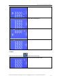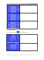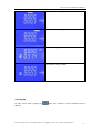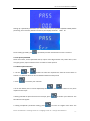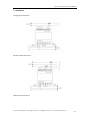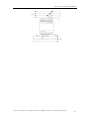
1
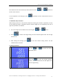
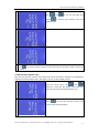
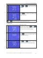
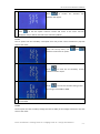
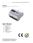
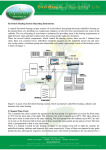
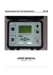
B+G E-Tech User Manual for SDM630 SDM630 Din Rail Smart Energy Meter for Single and Three Phase Electrical Systems USER MANUAL 2013 V1.1 B+G E-Tech User Manual for SDM630 Important Safety Information is contained in the Maintenance section. Familiarize yourself with this information before attempting installation or other procedures. Symbols used in this document: Risk of Danger: These instructions contain important safety information: Read them before starting installation or servicing of the equipment Caution: Risk of Electric Shock B+G E-Tech User Manual for SDM630 1 Introduction This document provides operating, maintenance and installation instructions . The unit measures and displays the characteristics of single phase two wires(1p2w) , three phase three wires(3p3w,) and three phase four wires(3p4w) supplies, including voltage, frequency, current, power ,active and reactive energy, imported or exported. Energy is measured in terms of kWh, kVArh. Maximum demand current can be measured over preset periods of up to 60minutes. In order to measure energy,the unit requires voltage and current inputs in addition tot he supply required to power the product.The requisite current input(s) are obtained via current transformers(CT). This meter can be configured to work with a wide range of CTs,giving the unit a wide range of operation.Built-in interfaces provides pulse and Rs485 Modbus RTU outputs.Configuration is password protected. This unit can be powered from a separate auxiliary(AC or DC)supply.Alternatively it can be powered from the monitored supply,where appropriate. 1.1 Unit Characteristics The Unit can measure and display: Line voltage and THD% (total harmonic distortion) of all phases Line Frequency Currents, Current demands and current THD% of all phases Power, maximum power demand and power factor Active energy imported and exported Reactive energy imported and exported The unit has password-protected set-up screens for: Changing password Supply system selection 1p2w, 3p3w,3p4w Demand Interval time Reset for demand measurements Pulse output duration Two pulse output indicates real-time energy measurement. An RS485 output allows remote monitoring from another display or a computer. 1.2 Current Transformer Primary Current The unit can be configured to operate with CT ratio between primary current and secondary current.The secondary CT has two options: 1A/5A 1.3 RS485 Serial – Modbus RTU This uses an RS485 serial port with Modbus RTU protocol to provide a means of remotely monitoring and controlling the Unit Set-up screens are provided for setting up the RS485 port. Refers to section 4.8 B+G E-Tech GmbH ° www.bg-etech.de ° [email protected] ° +49 (0) 3574 46755-0 -1- B+G E-Tech User Manual for SDM630 1.4 Pulse output This provides two pulse outputs that clock up measured active and reactive energy. The constant for reactive energy is 3200imp/kVArh. The pulse width for active energy can be set from the set-up menu. 2. Start Up Screens The first screen lights up all display segments and can be used as a display check The second screen indicates the firmware installed in the unit and its build number. The interface performs a self-test and indicates the result if the test passes. After a short delay, the screen will display active energy measurements. 3. Measurements The buttons operate as follows: Selects the Voltage and Current display screens In Set-up Mode, this is the “Left” or “Back” button. Select the Frequency and Power factor display screens In Set-up Mode, this is the “Up” button Select the Power display screens In Set-up Mode, this is the “Down” button B+G E-Tech GmbH ° www.bg-etech.de ° [email protected] ° +49 (0) 3574 46755-0 -2- B+G E-Tech User Manual for SDM630 Select the Energy display screens In Set-up mode, this is the “Enter” or “Right” button 3.1 Voltage and Current Each successive pressing of the button selects a new range: Phase to neutral voltages Current on each phase Phase to neutral voltage THD% Current THD% for each phase 3.2 Frequency and Power factor and Demand Each successive pressing of the button selects a new range: B+G E-Tech GmbH ° www.bg-etech.de ° [email protected] ° +49 (0) 3574 46755-0 -3- B+G E-Tech User Manual for SDM630 Frequency and Power Factor (total) Power Factor of each phase Maximum Power Demand Maximum Current Demand 3.3 Power Each successive pressing of the button select a new range: Instantaneous Active Power in kW B+G E-Tech GmbH ° www.bg-etech.de ° [email protected] ° +49 (0) 3574 46755-0 -4- B+G E-Tech User Manual for SDM630 Instantaneous Reactive Power in kVAr Instantaneous Volt-amps in KVA Total kW, kVArh, kVA 3.4 Energy Measurements Each successive pressing of the button selects a new range: Imported active energy in kWh Exported active energy in kWh B+G E-Tech GmbH ° www.bg-etech.de ° [email protected] ° +49 (0) 3574 46755-0 -5- B+G E-Tech User Manual for SDM630 Imported reactive energy in kVArh Exported reactive energy in kVArh Total active energy in kWh Total reactive energy in kVAh 4. Setting Up To enter set-up mode, pressing the button for 3 seconds, until the password screen appears. B+G E-Tech GmbH ° www.bg-etech.de ° [email protected] ° +49 (0) 3574 46755-0 -6- B+G E-Tech User Manual for SDM630 Setting up is password-protected so you must enter the correct password (default ‘1000’) before processing. If an incorrect password is entered, the display will show: PASS Err To exit setting-up mode, press repeatedly until the measurement screen is restored. 4.1 Set-up Entry Methods Some menu items, such as password and CT, require a four-digit number entry while others, such as supply system, require selection from a number of menu options. 4.1.1 Menu Option Selection 1. Use the and buttons to select the required item from the menu shown in section 4.1. selection does not roll over between bottom and top of list 2. Press to confirm your selection 3. If an item flashes, then it can be adjusted by the and buttons. If not, there maybe a further layer. 4. Having selected an option from the current layer, press to confirm your selection. The SET indicator will appear. 5. Having completed a parameter setting, press to return to a higher menu level. The B+G E-Tech GmbH ° www.bg-etech.de ° [email protected] ° +49 (0) 3574 46755-0 -7- B+G E-Tech User Manual for SDM630 SET indicator will be removed and you will be able to use the and buttons for further menu selection. 6. On completion of all setting-up, press repeatedly until the measurement screen is restored. 4.1.2 Number Entry Procedure When Setting up the unit , some screens require the entering of a number. In particular, on entry to the setting up section, a password must be entered. Digits are set individually, from left to right. The procedure is as follows: 1. the current digit to be set flashes and is set using the 2. Press and buttons to confirm each digit setting. The SET indicator appears after the last digit has been set. 3. After setting the last digit, press to exit the number setting routine. The SET indicator will be removed. 4.2 Change password 1 Use the and to choose the change password option 2 Press the to enter the change password routine. The new password screen will appear with the first digit flashing B+G E-Tech GmbH ° www.bg-etech.de ° [email protected] ° +49 (0) 3574 46755-0 -8- B+G E-Tech User Manual for SDM630 3 Use press and to set the first digit and to confirm your selection. The next digit will flash. 4 Repeat the procedure for the remaining three digits 5 After setting the last digit, SET will show. 6 Press to exit the number setting routine and return to the Set-up menu. SET will be removed 4.3 DIT Demand Integration Time This sets the period in minutes over which the current and power readings are integrated for maximum demand measurement. The options are: off, 5, 10,15 30,60 minutes 1 From the set-up menu, use and buttons to select the DIT option. The screen will show the currently selected integration time. 2 Press to enter the selection routine. The current time interval will flash B+G E-Tech GmbH ° www.bg-etech.de ° [email protected] ° +49 (0) 3574 46755-0 -9- B+G E-Tech User Manual for SDM630 3 Use and buttons to select the time required. 4 Press to confirm the selection. SET indicator will appear. 5 Press to exit the DIT selection routine and return to the menu. 4.4 Supply System Use this section to set the type of power supply being monitored. 1 From the Set-up menu, use and buttons to select the System option. The screen will show the currently selected power supply . 2 Press to enter the selection routine. The current selection will flash 3 Use and buttons to select the required system option: 1P2(W),3P3(W) ,3P4(W) B+G E-Tech GmbH ° www.bg-etech.de ° [email protected] ° +49 (0) 3574 46755-0 - 10 - B+G E-Tech User Manual for SDM630 4 Press to confirm the selection. SET indicator will appear. 5 Press to exit the system selection routine and return to the menu. SET will disappear and you will be returned to the main Set-up Menu 4.5 CT The CT option sets the secondary current(CT2 1A or 5A) of the current transformer (CT) that wires to the meter. 1 From the Set-up menu, use and buttons to select the CT option. 2 Secondary CT setting Press to enter the CT secondary current selection routine.:5A/1A 3 Set CT Ratio value Press to enter the CT Ratio setting screen. The range is from 0001 to 9999. 4 For example,if set the ratio to be 100,it means the primary current equals secondary currentx100 4.6 PT The PT option sets the secondary voltage (PT2 100 to 500V) of the Voltage transformer (PT) that wires to the meter. B+G E-Tech GmbH ° www.bg-etech.de ° [email protected] ° +49 (0) 3574 46755-0 - 11 - B+G E-Tech User Manual for SDM630 1 From the Set-up menu, use and buttons to select the PT option. The screen will show the voltage PT secondary voltage value. The default value is 230V 2 Secondary PT setting Press to enter the PT secondary voltage selection routine. The range is from 100 to 500V 3 Set PT ratios value Press to enter the PT ratio screen. The range is from 0001 to 9999 4 For example,if set the ratio to be 100,it means the primary voltage equals secondary voltagex100 4.7Pulse output This option allows you to configure the pulse output. The output can be set to provide a pulse for a defined amount of energy active or reactive. Use this section to set up the relay pulse output—Units: kWh , kVArh 1 From the Set-up menu, use and buttons to select the Pulse output option. 2 Press to enter the selection routine. The unit symbol will flash. B+G E-Tech GmbH ° www.bg-etech.de ° [email protected] ° +49 (0) 3574 46755-0 - 12 - B+G E-Tech User Manual for SDM630 3 Use and buttons to choose kWh or kVArh. 4 On Completion of the entry procedure, press to confirm the setting and press to return to the main set up menu. 4.7.1 Pulse rate Use this to set the energy represented by each pulse. Rate can be set to 1 pulse per 0.01kWh/0.1kWh/1kWh/10kWh/100kWh. (It shows 1 impulse = 10kWh/kVArh) 1 From the Set-up menu, use and buttons to select the Pulse Rate option. 2 Press to enter the selection routine. The current setting will flash. 0.01/0.1/1/10/100kWh/kVarh per pulse 3 Use and procedure, press buttons to choose pulse rate.On Completion of the entry to confirm the setting and press to return to the main set up menu. 4.7.2 Pulse Duration The energy monitored can be active or reactive and the pulse width can be selected as 200, 100 or 60ms. B+G E-Tech GmbH ° www.bg-etech.de ° [email protected] ° +49 (0) 3574 46755-0 - 13 - B+G E-Tech User Manual for SDM630 (It shows pulse width of 200ms) 1 From the Set-up menu, use and buttons to select the Pulse width option. 2 Press to enter the selection routine. The current setting will flash. 3 Use and procedure, press buttons to choose pulse width.On Completion of the entry to confirm the setting and press to return to the main set up menu. 4.8 Communication There is a RS485 port can be used for communication using Modbus RTU protocol. For Modbus RTU, parameters are selected from Front panel. 4.8.1 RS485 Address (The range is from 0 to 247) 4.8.2 Baud Rate B+G E-Tech GmbH ° www.bg-etech.de ° [email protected] ° +49 (0) 3574 46755-0 - 14 - B+G E-Tech User Manual for SDM630 1 From the Set-up menu, use and buttons to select the Baud Rate option. 2 Press to enter the selection routine. The current setting will flash. 3 Use and buttons to choose Baud rate 2.4k. 4.8k, 9.6k, 19.2k, 38.4k 4 On Completion of the entry procedure, press to confirm the setting and press to return to the main set up menu. 4.8.3 Parity 1 From the Set-up menu, use and buttons to select the Parity option. 2 Press to enter the selection routine. The current setting will flash. 3 Use and buttons to choose Parity (EVEN / ODD / NONE) 4 On Completion of the entry procedure, press to confirm the setting and press B+G E-Tech GmbH ° www.bg-etech.de ° [email protected] ° +49 (0) 3574 46755-0 - 15 - B+G E-Tech User Manual for SDM630 to return to the main set up menu. 4.8.4 Stop bits 1 From the Set-up menu, use and buttons to select the Stop Bit option. 2 Press to enter the selection routine. The current setting will flash. 3 Use and buttons to choose Stop Bit (2 or 1) 4 On completion of the entry procedure, press to confirm the setting and press to return to the main set up menu. 4.9 CLR The meter provides a function to reset the maximum demand value of current and power. 1 From the Set-up menu, use and buttons to select the reset option. 2 Press to enter the selection routine. The dIt will flash. 3 Press to confirm the setting and press to return to the main set up menu. B+G E-Tech GmbH ° www.bg-etech.de ° [email protected] ° +49 (0) 3574 46755-0 - 16 - B+G E-Tech User Manual for SDM630 5 Specifications 5.1 Measured Parameters The unit can monitor and display the following parameters of a single phase two wire(1p2w), three phase three wire(3p3w) or four phase four wire(3p4w) supply. 5.1.1 Voltage and Current Phase to neutral voltages 100 to 289V a.c. (not for 3p3w supplies) Voltages between phases 173 to 500V a.c. (3p supplies only) Percentage total voltage harmonic distortion (THD%) for each phase to N ( not for 3p3w supplies) Percentage voltage THD% between phases (three phase supplies only) Current THD% for each phase 5.1.2 Power factor and Frequency and Max. Demand Frequency in Hz Instantaneous power: Power 0 to 3600 MW Reactive Power 0 to 3600 MVAr Volt-amps 0 to 3600 MVA Maximum demanded power since last Demand reset Power factor Maximum neutral demand current, since the last Demand reset (for three phase supplies only) 5.1.3 Energy Measurements Imported active energy 0 to 9999999.9 kWh Exported active energy 0 to 9999999.9 kWh Imported reactive energy 0 to 9999999.9 kVArh Exported reactive energy 0 to 9999999.9 kVArh Total active energy 0 to 9999999.9 kWh Total reactive energy 0 to 9999999.9 kVArh 5.2 Measured Inputs Voltage inputs through 4-way fixed connector with 2.5mm² stranded wire capacity. single phase two wire(1p2w), three phase three wire(3p3w) or four phase four wire(3p4w) unbalanced. Line frequency measured from L1 voltage or L3 voltage. Three current inputs (six physical terminals) with 2.5mm² stranded wire capacity for connection of external CTs. Nominal rated input current 5A or 1A a.c. Rms. 5.3 Accuracy Voltage Current Frequency Power factor Active power (W) 0·5% of range maximum 0·5% of nominal 0·2% of mid-frequency 1% of unity (0.01) ±1% of range maximum B+G E-Tech GmbH ° www.bg-etech.de ° [email protected] ° +49 (0) 3574 46755-0 - 17 - B+G E-Tech User Manual for SDM630 Reactive power (VAr) Apparent power (VA) Active energy (Wh) Reactive energy (VARh) Total harmonic distortion Temperature co-efficient Response time to step input ±2% of range maximum ±1% of range maximum Class 1 IEC 62053-21 ±2% of range maximum 1% up to 31st harmonic Voltage and current = 0.013%/°C typical Active energy = 0·018%/°C, typical 1s, typical, to >99% of final reading, at 50 Hz. 5.4 Auxiliary Supply Two-way fixed connector with 2·5mm2 stranded wire capacity. 85 to 275V a.c. 50/60Hz ±10% or 120V to 380V d.c. ±20%. Consumption < 10W. 5.5 Interfaces for External Monitoring Three interfaces are provided: an RS-485 communication channel that can be programmed for Modbus RTU protocol an relay output indicating real-time measured energy.(configurable) an pulse output 3200imp/kWh (not configurable) The Modbus configuration (Baud rate etc.) and the pulse relay output assignments (kW/kVArh, import/export etc.) are configured through the Set-up screens. 5.5.1 Pulse Relay Output The pulse relay output can be set to generate pulses to represent kWh or kVArh. Rate can be set to generate 1 pulse per: 0.01 = 10 Wh/VArh 0.1 = 100 Wh/VArh 1 = 1 kWh/kVArh 10 = 10 kWh/kVArh 100 = 100 kWh/kVArh Pulse width 200/100/60 ms. Relay Rating 240V ac 50mA 5.5.2 RS485 Output for Modbus RTU For Modbus RTU, the following RS485 communication parameters can be configured from the Set-up menu: Baud rate 2400, 4800, ,9600, ,19200, 38400 Parity none/odd/even Stop bits 1 or 2 RS485 network address nnn – 3-digit number, 1 to 247 Modbus™ Word order Hi/Lo byte order is set automatically to normal or reverse. It cannot be configured from the set-up menu. 5.6 Reference Conditions of Influence Quantities B+G E-Tech GmbH ° www.bg-etech.de ° [email protected] ° +49 (0) 3574 46755-0 - 18 - B+G E-Tech User Manual for SDM630 Influence Quantities are variables that affect measurement errors to a minor degree. Accuracy is verified under nominal value (within the specified tolerance) of these conditions. Ambient temperature 23°C ±1°C Input waveform 50 or 60Hz ±2% Input waveform Sinusoidal (distortion factor < 0·005) Auxiliary supply voltage Nominal ±1% Auxiliary supply frequency Nominal ±1% Auxiliary supply waveform (if AC) Sinusoidal (distortion factor < 0·05) Magnetic field of external origin Terrestrial flux 5.7 Environment Operating temperature Storage temperature Relative humidity Altitude Warm up time Vibration Shock -25°C to +55°C* -40°C to +70°C* 0 to 90%, non-condensing Up to 2000m 1 minute 10Hz to 50Hz, IEC 60068-2-6, 2g 30g in 3 planes *Maximum operating and storage temperatures are in the context of typical daily and seasonal variation. 5.8 Mechanics DIN rail dimensions Mounting Sealing Material 72 x 94.5 mm (WxH) per DIN 43880 DIN rail (DIN 43880) IP20 (minimum) Self-extinguishing UL 94 V-0 6 Dimensions B+G E-Tech GmbH ° www.bg-etech.de ° [email protected] ° +49 (0) 3574 46755-0 - 19 - B+G E-Tech User Manual for SDM630 7. Installation 1)Single phase two wires 2) Three phase three wires 3)Three phase four wires B+G E-Tech GmbH ° www.bg-etech.de ° [email protected] ° +49 (0) 3574 46755-0 - 20 - B+G E-Tech User Manual for SDM630 B+G E-Tech GmbH ° www.bg-etech.de ° [email protected] ° +49 (0) 3574 46755-0 - 21 -