1
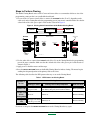
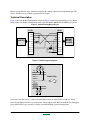
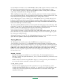
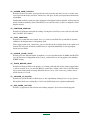
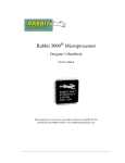
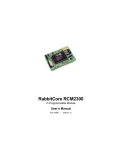
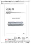
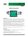
TN207
Rabbit Cloning Board
Introduction
The Rabbit Cloning Board copies designated portions of flash memory from one Rabbit-based controller
(the master) to another (the clone). Dynamic C version 6.50 or later is needed to use the cloning board.
Fast cloning, where the data transfer rate is the maximum allowed by the crystal frequency, was introduced
in Dynamic C version 7.05. Other options were added to be used with fast cloning. In fast cloning, the size
of the program to be cloned was limited by the size of the RAM, and programs that spanned two flash
devices could not be cloned. The options used with fast cloning were in the Dynamic C library
LIB\BIOSLIB\fastclone.lib.
The restrictions on fast cloning have been removed starting with Dynamic C 7.20; fast cloning is the only
implementation available or needed. Dynamic C 7.20 makes available more cloning options; the options
can be set using the cloning configuration macros near the top of BIOS\RABBITBIOS.C or in
Lib\BIOSLIB\cloneconfig.lib, depending on your version of Dynamic C. With later versions of
Dynamic C you can use the “Defines” tab found in the Options | Project Options dialog to define the cloning macros.
For a description of the various options, please see the section on “Cloning Macros” on page 5.
Key Benefits
• The Rabbit Cloning Board replaces a PC or EPROM burner as the primary tool to load programs, thus
•
•
•
•
reducing costs and workspace.
Programs may be loaded quickly onto blank, soldered on flash devices.
High-speed data transfer at 57,600 bps or 115,200 bps.
Higher-speed data transfer of up to 921,600 bps starting with Dynamic C version 7.05.
Ideal for low-volume cloning production.
022-0050 Rev. K
rabbit.com
1
Steps to Enable and Set Up Cloning
Before cloning begins the master controller must be readied. Follow these steps:
1. Connect the programming port of your master controller to a PC running Dynamic C (see Figure 1). Use
the programming cable that came with the controller and follow the instructions in the controller user’s
manual.
Figure 1. Enable Cloning on Master Controller
MASTER CONTROLLER
PROGRAMMING
CABLE
D
I
A
G
J2
To
PC COM port
P
R
O
G
PROG
PORT
Colored side
to pin 1
CMOS to RS-232
level converter
2. Apply power to the controller.
3. For older versions of Dynamic C1, open the BIOS file: BIOS\RABBITBIOS.C.
4. Change the line
#define ENABLE_CLONING 0
// set to 1 to enable cloning
to
#define ENABLE_CLONING 1
// set to 1 to enable cloning
NOTE: Various options are enabled by the macros described in “Cloning Macros” on page 5.
These macros are found in the BIOS or the configuration library and any change to their values
must be made as part of Step 4.
5. Save the change(s) to RABBITBIOS.C and close the file.
6. Open the application program to compile to the master controller.
7. Click on the Compile to Target item in the Compile menu.
8. Remove power from the controller and disconnect the programming cable from the controller’s programming port.
NOTE: If ENABLE_FAST_CLONING (available in Dynamic C versions 7.05 to 7.10 only) was
set to 1 in the BIOS as part of step 4, other fast cloning options are available in
LIB\BIOSLIB\fastclone.lib. These macros are functionally the same as the macros of
similar name that begin with “CL” instead of “FC” that are described in “Cloning Macros” on
page 5. The associated macros are:
•
•
•
•
FC_ASSUME_SAME_CRYSTAL
FC_CHECKSUM_ENABLED
FC_DOUBLE_CLONE_CLOCK
FC_RUN_AFTER_COPYING
1. For newer versions of Dynamic C use the “Defines” tab on the Options | Project Options dialog to define
cloning macros.
2
rabbit.com
TN207
Steps to Perform Cloning
The Rabbit Cloning Board comes with 1.27 mm and 2 mm cables to accommodate whichever size of the
programming connector that is on your Rabbit-based board.
1. Use one of the 1.27 mm or 2 mm cables to connect the MASTER header (J3 or J1, depending on the
cable used) on the Cloning Board to the programming port of your master controller. Make sure that the
colored side of the cable goes to pin 1 of the header as shown in Figure 2.
Figure 2. Cloning Cable Connections to the Rabbit Cloning Board
CLONING BOARD
MASTER
TARGET
RABBIT CLONING
MASTER
Colored side
UP
J2
J1
2 mm
pitch
2 mm
pitch
RESET MASTER
CLONE STATUS
DS1
S1
R1
J3
J4
1.27 mm
pitch
1.27 mm
pitch
MASTER
Colored side
DOWN
CLONE
TARGET
BEING
CLONED
175-0247 REV. A
2. Use the other cable to connect the CLONE header (J4 or J2) on the Cloning Board to the programming
port of the target controller. Make sure that the colored side of the cable goes to pin 1 of the header as
shown in Figure 2.
3. Apply power to both the master and the target.
4. Press the RESET MASTER button on the Rabbit Cloning Board to initiate cloning. The master begins
sending the designated portion of the primary flash to the clone.
The following table describes the LED patterns that may occur on the Cloning Board.
Table 1. LED Patterns on Cloning Board
Dynamic C
Version
Up thru 7.06
Cloning Status
Cloning is active
LED blinks several
times per second.
Cloning successfully completed
Error occurred
LED will blink quickly in a distinctive pattern of
LED stops blinking.
four flashes, then pause, then four more flashes…
7.05 thru 7.10
LED is off.
in fast
cloning mode
LED is on.
Starting with LED toggles on and off
LED stays on.
7.20
about once per second.
LED starts blinking.
LED starts blinking.
If an error occurs press the RESET MASTER button on the Cloning Board to try again.
TN207
rabbit.com
3
Remove power from the target controller and unplug the cloning cable from its programming port. The
master controller is now available to program the next target.
Technical Description
Figure 3 shows the Rabbit Cloning Board circuit and Figure 4 shows the programming port on a Rabbit
based product. The Rabbit Cloning Board works with both Rabbit 2000-based and 3000-based systems.
Figure 3. Rabbit Cloning Board Circuit
J1/J3
RXA
GND
CLKA
MASTER
+5 V
/RESET
TXA
N/C
STATUS
SMODE0
SMODE1
J2/J4
1
1
2
2
3
3
4
4
5
5
RESET MASTER
6
7
7
8
8
9
CLONE STATUS
9
10
10
470 W
RXA
GND
CLKA
+5 V
/RESET
TXA
TARGET
BEING
CLONED
N/C
STATUS
SMODE0
SMODE1
Figure 4. Rabbit Programming Port
~5 kW
~50 kW
RXA
~50 kW
VDD
VSS
CLKA
Rabbit Chip
VDD
/RESET
TXA
STATUS
SMODE0
~50 kW
~50 kW
SMODE1
The master controller detects a connected Cloning Board when the signal CLKA is held low. This is
detected in the BIOS when the reset ends and the cloning support of the BIOS is invoked. The cloning program cold-boots the target system by resetting it and downloading a primary boot program.
4
rabbit.com
TN207
On some Rabbit core modules, such as the RCM4200, the PB1 (CLKA) signal is either not available or not
pulled up on the programming port, the master can be forced to invoke cloning support by setting
CL_FORCE_MASTER_MODE to 1. This will cause the BIOS to assume a cloning cable is attached on
every startup, assuring that only the cloning code will run.
While compiling to the target with CL_FORCE_MASTER_MODE set to 1, the loss of target communication is expected and unavoidable. After the program has loaded and target communication is lost the clone
master will still correctly perform its cloning function after a cloning cable is attached.
Since the BIOS supports a variety of flash types, the flash EPROM on the two controllers do not have to
be identical. Cloning works between master and target controllers that have different-sized flash chips
because the master copies its own universal flash driver to the target. The flash driver determines the particulars of the flash chip on which it is running.
The master controller’s BIOS must allocate a memory buffer sufficiently large to work on the target. Prior
to Dynamic C version 7.02, the cloning software used root memory for this buffer, which reduces the root
memory available to the application program. The size of the buffer is given by the macro
MAX_FLASH_SECTORSIZE. This macro is defined near the top of the
LIB\BIOSLIB\FLASHWR.LIB file. The default value is 1024 (4096 in older versions). The user can
reduce this buffer size to the maximum of the master and target’s sector sizes if root data space is a problem, or increase it to 4096 if needed.
Starting with Dynamic C version 7.02, the cloning implementation uses xmem for the buffer, so root data
space will not be a problem; and no changes should be made to FLASHWR.LIB.
Cloning Macros
The following macros are in the source code of the BIOS (BIOS\RABBITBIOS.C) or in
Lib\BIOSLIB\cloneconfig.lib, depending on the version of Dynamic C. The default values
may be changed there. In later versions of Dynamic C you can change the defaults by defining the macros
in the “Defines” tab located in the Options | Project Options dialog. If a particular macro is not defined in
the BIOS file or the configuration library, then the associated option is not available in the version of
Dynamic C you are using. The exception to this are the fast cloning options enabled by the FC_* macros
in fastclone.lib.
ENABLE_CLONING
Default is 0: cloning is not enabled. Set to 1 to enable cloning. The cloning implementation in
Dynamic C version 7.10 requires that ENABLE_FAST_CLONING and ENABLE_CLONING be set to
1 to enable cloning.
If PB1 is either not available or not pulled in the design, CL_FORCE_MASTER_MODE should be set
to 1 to force the board to assume that a cloning cable is always attached.
CLONE_WHOLE_FLASH
Default is 0: only compiled program will be copied. Set to 1 to copy entire flash device, which
excludes the system ID block unless CL_INCLUDE_ID_BLOCKS is set to 1 also. Excludes secondary flash device, but if the program being cloned extends into the second flash, it will be copied
regardless of this setting.
TN207
rabbit.com
5
CL_ASSUME_SAME_CRYSTAL
Default is 0: does not assume crystal speed is the same on master and clone. Set to 1 to assume same
crystal speed on the master and clone, which saves code space for the crystal speed measurement and
autobauding.
Autobauding works by setting the clone and master to the highest baud rate possible, and lowering the
master's baud rate until they match. This MUST be set to 0 if the clone's crystal is, or might be, slower
than the master's.
CL_CHECKSUM_ENABLED
Default is 0: do Internet checksum for cloning. Leaving this as 0 will save some code size and a little
time. Uses RFC 1071 method.
CL_COPY_2NDFLASH
Default is 0: second flash is not cloned. Set to 1 to clone second flash. The second flash is cloned in
addition to the designated area of the primary flash.
This is separate from USE_2NDFLASH_CODE so that files in the secondary flash can be copied too if
desired. This will cause the whole second flash to be copied unconditionally even if the program
doesn't use two flashes.
CL_DOUBLE_CLONE_CLOCK
Default is 0: If the cloned board has or might have a crystal speed more than 12.9MHz, this MUST be
set to 0. This macro is independent of the CLOCK_DOUBLED macro. It only applies clock doubling
WHILE cloning.
CL_FORCE_MASTER_MODE
Default is 0: Master will detect the presence of a cloning cable and only invoke cloning support when
a cable is attached. Set to 1 to force the BIOS to assume that a cloning cable is always attached and to
always enter cloning mode on startup. When this macro is set to 1, the STERILE_CLONES macro
will be forced to 1 as well.
CL_INCLUDE_ID_BLOCKS
Default is 0: System ID and User block areas are not copied during cloning. Set to 1 to copy System
ID and User block areas. Setting this to 1 will cause the ID blocks to be copied unconditionally.
CL_RUN_AFTER_COPYING
Default is 1: program on clone will run after cloning completes. Set to 0 to not run the program.
6
rabbit.com
TN207
INITIAL_SLV_BAUD_DIV
Default is 0. If the clone is faster than, or might be faster than, the master, increase this macro to the
value needed to achieve the fastest common baud rate that works on both boards. Zero will always
work when the clone crystal speed is equal to the master crystal speed. (This is the value that goes in
the divisor register, the actual divisor is this plus 1.)
The divisor register value is determined as follows:
Divisor Register Value
(Crystal Frequency (in Hz))
= ------------------------------------------------------------------ – 1
32 × baud rate
For achievable baud rates, this should within 4% of an integral value. The maximum baud rate is the
crystal frequency (in Hz) divided by 32. Note that if CL_DOUBLE_CLONE_CLOCK = 1, the crystal
frequency is doubled in the above calculation.
STERILE_CLONES
Default is 0: cloned boards will check for the presence of a cloning cable. Set to 1 to cause cloned
boards to bypass the check for the cloning cable, thereby disabling cloning of clones.
In some core modules the default is 1 and cannot be changed, thus making all clones sterile. A compiler error is generated if an attempt is made to define this macro to “0” on a core module that does not
support non-sterile clones.
CLONINGBAUDRATE (Dynamic C versions prior to version 7.20 only)
Default is 1: baud rate is 115,200 bps. Set to 0 to use 57,600 bps. This macro is not applicable when
ENABLE_FAST_CLONING is set to 1.
All controllers sold by Rabbit Semiconductor with the Rabbit 2000™ or the Rabbit 3000™ chip support
cloning at 115,200 bps. If you have a custom designed Rabbit-based controller with a crystal that does
not support a baud rate of 115,200 bps, change this macro to zero and the baud rate will be 57,600 bps.
ENABLE_FAST_CLONING (Dynamic C versions 7.05 to 7.10 only)
Default is 0: fast cloning is not enabled. Set to 1 to enable fast cloning.
This macro was made available to speed up the cloning process, with some restrictions. See the
description of the ENABLE_FAST_CLONING macro near the beginning of RABBITBIOS.C for
details.
The cloning implementation in Dynamic C version 7.20 transfers data at the fastest possible speed
allowed by the crystal frequency, making the ENABLE_FAST_CLONING macro unnecessary.
Summary
The Rabbit Cloning Board is an easy-to-use, inexpensive solution for low production cloning. It is fast,
flexible and reliable.
TN207
rabbit.com
7