1
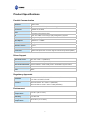
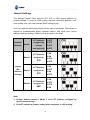
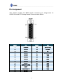
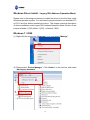
USER’S MANUAL Universal PCI Remap Parallel Communication Board English Version First Edition, April 2010 SUNIX Co., Ltd. Tel : +886-2-8913-1987 Fax: +886-2-8913-1986 Http://www.sunix.com.tw [email protected] ___________________________________________________________________________________ Universal PCI Remap Parallel Communication Board User’s Manual Copyright Copyright© 2010 SUNIX Co., Ltd. All Rights Reserved. No part of this publication may be reproduced, transcribed, stored in a retrieval system, translated into any language, or transmitted in any from or by any means, photocopying, manual, or otherwise, without prior written permission from SUNIX. Disclaimer SUNIX shall not be liable for any incidental or consequential damages resulting from the performance or use of this equipment. SUNIX makes no representations or warranties regarding the contents of this manual. Information in this manual has been carefully checked for reliability; however, no guarantee is given as to the correctness of this content. In the interest of continued product improvement, this company reserves the right to revise the manual or include change in the specifications of the product described within it at any time without notice and without obligation to notify any person of such revision or changes. The information contained in this manual is provided for general use by the customers. Trademarks SUNIX is a registered trademark of SUNIX Group. All other trademarks or registered marks in this manual belong to their respective owners. Safety Information 1. Keep this User’s Manual for future reference. 2. Always read the safety information carefully. 3. Keep this equipment away from direct sunlight, or in humid or damp places. 4. Do not place this equipment in an unstable position, or on vibrating surface before setting it up. 5. Do not use or place this equipment near magnetic fields, televisions, or radios to avoid electronic interface that affects device performance. 1 ___________________________________________________________________________________ Table of Contents Chapter 1 Introduction...............................................................................................4 Overview ........................... ............................................................................ 5 Package Checklist ......................................................................................... 5 Product Features ........................................................................................... 6 Product Specifications ................................................................................... 7 Chapter 2 Hardware Installation................................................................................8 Hardware Installation .................................................................................... 9 Pin Assignment ........................................................................................... 10 Chapter 3 Software Installation ..............................................................................12 Windows Driver Install ..…………….. .. .. ……………....................................13 Windows Driver Uninstall ............... .. .. .. ..................................................... 34 Windows Verify Installation .......................................................................... 35 Linux Driver Install ..……. …. …....................................................................36 Chapter 4 Port Configuration ..................................................................................38 Configure LPT Port Settings……………………….. .......................................39 LPT I/O Resource …..…...................................... ... .....................................39 LPT Port Number Settings...................................... ..................................... 40 Chapter 5 Appendix …………................................................................................41 Troubleshooting ......................................................................................... 42 Contact Information ................................................................................... 44 2 ___________________________________________________________________________________ WHQL Certification Approval The Designed for Microsoft Windows 32/64-bit operation system WHQL logo identifies products that meet Microsoft’s quality standards, SUNIX I/O products carry with this logo and listed on Windows Catalog. WHQL logo includes below operation system version Microsoft Windows Client: Windows 2000 / XP / Vista / 7 (X86/X64) Microsoft Windows Server: Windows 2003 / 2008 (X86/X64) 3 ___________________________________________________________________________________ 1. Introduction ______________________________________________ SUNIX Golden I/O series, a line of Universal PCI Remap Parallel Communication Board, is designed for both 3.3 / 5V and 32 / 64-bit PCI Bus with Plug and Play feature. Its can be installed in virtually any available PC system and compatible with all major operating systems.. This board supports independent parallel LPT port for connecting printers, IC programmers, ZIP Drives, or other Parallel devices The following topics covered in this chapter: Overview Package Checklist Product Features Product Specifications 4 ___________________________________________________________________________________ Overview Thanks for purchasing SUNIX Universal PCI Parallel Communication Board. SUNIX PAR5008D card enables users to expand one additional real ECP/EPP/SPP/BPP communication LPT port on their PC-based system for connecting their parallel devices. Furthermore, this board can be installed as a fully featured I/O mapped parallel port as 278, 378, and 3BC legacy ISA address under Microsoft Windows and DOS operation systems. User can connect software protection dongles, JTAG chip programmers, data acquisition, machine process control, scientific measurement systems, and other parallel devices as well as computer's native parallel port. SUNIX PAR5008D Remap card is designed with SUNIX high performance and realizable parallel connectivity controller, UL7512EQ and as well built with many of SUNIX advanced features and technologies, making it the advanced and high efficient solution for commercial and industrial automation applications. Package Checklist Please check if the following items are present and in good condition upon opening your package. Contact your vendor if any item is damaged or missing. 1. Hardware: Universal PCI Remap Parallel Communication Board 2. CD Driver 3. User's Manual (This document) 5 × 1 ___________________________________________________________________________________ Product Features High reliability SUNIX UL7512EQ Parallel controller on-board. Expand single IEEE1284 compatible DB-25 type Parallel port on system. Universal PCI compatible with 64/32-bit PCI-X/PCI Bus. Compliance with PCI 33MHz Version 3.0/2.3/2.2/2.1 specification. Support IEEE 1284-1994 parallel port standard. ECP (Enhance Capacity Port) / EPP (Enhance Parallel Port) SPP (Standard Parallel Port) / BPP (Bi-direction Parallel Port) Auto-switching between ECP/EPP/SPP/BPP modes without configuration. Support legacy ISA address (278, 378, 3BC) or PCI Plug-n-Play modes. Install as a fully featured I/O mapped as computer's native parallel LPT port. Certified by CE, FCC, RoHS, and Microsoft WHQL approval. Support Microsoft Windows, Linux, and DOS operation system. 6 ___________________________________________________________________________________ Product Specifications Parallel Communication Interface IEEE-1284 Mode SPP/ECP/EPP/BPP ( Auto-switching) Controller IO SUNIX UL7512EQ Universal PCI 64/32bit PCI Spec.Ver3.0/2.3/2.2/2.1 378, 278, 3BC or PCI Plug-n-play Assigned by System IRQ & Assigned by System Data Speed Maximum 1.8 MB/s FIFO 16 byte Hardware Number of Port 1-port Board Connector DB25 Female Protection ±2KV ESD protection for each signal Human Body Model (HBM) BUS Driver Support Microsoft Client 98 / XP / Vista / 7 (X86/X64) Microsoft Server 2000 / 2003 / 2008 (X86/X64) Microsoft Embedded XP Embedded / POS Ready 2009 / Embedded System 2009 Linux Linux 2.4.x / 2.6.x DOS DOS Regulatory Approvals Hardware Software EN55022 Class B, EN55024, EN61000-3-2, EN61000-3-3, FCC Part 15 Class B, RoHS Microsoft WHQL Windows Microsoft Client: XP / Vista / 7 (X86/X64) Microsoft Server: 2000 / 2003 / 2008 (X86/X64) Environment Operation Temperature Operation Humidity Storage Temperature 0 to 60°C (32 to 140°F) 5 to 95% RH -20 to 85°C (-4 to 185°F) 7 ___________________________________________________________________________________ 2. Hardware Installation ______________________________________________ This chapter includes information about hardware installation and jumper settings for Universal PCI Remap Parallel Communication Board. The following topics are covered: Hardware Installation Jumper Settings Pin Assignments 8 ___________________________________________________________________________________ Hardware Installation The hardware installation of PCI parallel board is easy to carry out. Before inserting the card into the PCI bus, please follow the detailed steps given below to install the PCI parallel board in your computer. Safety First To avoid damaging your system and boards, make sure your PC’s power is turned off before installing PCI card. Step 1: Turn your PC’s power off, and shut off the power to any peripheral. Step 2: Remove the power plug from the plug socket. Step 3: Remove the cover from the computer case. Step 4: If fitted. Remove the metal cover plate on the rear of a free PCI slot. Step 5: Insert Universal PCI Parallel Communication Board into the free PCI slot and screw it firmly on the bracket side. (Please set on board jumper firstly, and then install this board) Step 6: Place the cover back onto the computer. Step 7: Insert the plug into the plug socket. 9 ___________________________________________________________________________________ Jumper Settings This Remap Parallel Card supports 278, 378, or 3BC legacy address by jumper settings. In order to avoid system resource conflicting problem, user must makes sure your main board’s BIOS settings firstly. User can read this silkscreen printing on the right of this board. The first pin is defined to enable/disable legacy address feature, and other pins control different address settings. Please refer to the picture for detail. Standard (Default) Mode 1 Mode 2 LPT Address assigned by system 1 OFF 2 OFF 3 OFF automatically 4 OFF LPT Address assigned to 378 Legacy ISA Address Settings Mode 3 LPT Address assigned to 278 Mode 4 LPT Address assigned to 3BC 1 ON 2 ON 3 OFF 4 OFF 1 ON 2 OFF 3 ON 4 OFF 1 ON 2 OFF 3 OFF 4 ON Note: 1. System default setting is Mode 1, and LPT Address assigned by system automatically. 2. Do NOT switch the jumper setting when computer is still running. 10 ___________________________________________________________________________________ Pin Assignment This chapter provides the DB25 female connector’s pin assignments for SUNIX Universal PCI Remap Parallel Communication Board. DB25F PIN DB25F PIN 1 STROBE 14 AUTO FEED 2 DATA0 15 ERROR 3 DATA1 16 INT 4 DATA2 17 SELECT INPUT 5 DATA3 18 GND 6 DATA4 19 GND 7 DATA5 20 GND 8 DATA6 21 GND 9 DATA7 22 GND 10 ACKNOWLEDGE 23 GND 11 BUSY 24 GND 12 PAPER EMPTY 25 GND 13 SELECT 11 ___________________________________________________________________________________ 3. Driver Installation ______________________________________________ After installing the Universal PCI Parallel Communication Board in your system successfully, please follow the step by step software installation guide to confirm how to install appropriate driver and configure the LPT port settings. Please note that there are different drivers and different installation guides for “Legacy ISA Address Operation mode” and “Standard PCI Plug-n-Play mode” under Windows operation system. The driver for PCI parallel board supports Windows and Linux operating systems, and you can select your requirement in the following chapter: The following topics covered in this chapter: Windows Driver Install - Legacy ISA Address Operation Mode * Windows 7/2008 * Windows Vista/XP/2003/2000/98 - Standard PCI Plug-n-Play Mode Windows Driver Uninstall Windows Verify Installation Linux Driver Install 12 ___________________________________________________________________________________ Windows Driver Install - Legacy ISA Address Operation Mode Please refer to following instructions to install the driver for the first time under Windows operation system. You will need to plug the board in an available PCI or PCI-X slot first, before installing the driver. This chapter makes a description of driver installation under Legacy ISA Address Operation Mode. Be sure to set jumper at Mode 2 (378), Mode 3 (278). or Mode 4 (3BC). Windows 7 / 2008 (1) Right-click the mouse on “Computer” icon, and select “Manage”. (2) Please select “Device Manager”. Click “Action” on the tool bar, and select “Add legacy hardware”. 2. 1. 13 ___________________________________________________________________________________ (3) Add Hardware Wizard window pops up. Please click “Next”. (4) Please select “Install the hardware that I manually select from a list”. 14 ___________________________________________________________________________________ (5) Please select “Ports (COM & LPT)”, and click “Next”. (6) Please select “ECP Printer Port” and click “Next”. 15 ___________________________________________________________________________________ (7) Please click “Next” to continue LPT port installation. (8) Please click “Finish” to end the Add Hardware Wizard. 16 ___________________________________________________________________________________ (9) There is a new ECP Printer Port (LPT3) with exclamation mark shown in the device manger. Note: This LPT port is not ready for using at this time. (10) Right-click the mouse on “LPT3” icon, and select “Properties”. 17 ___________________________________________________________________________________ (11) Go to “Resource” table and click “Set Configuration Manually”. (12) Select “I/O Range” icon. “Uncheck” the Use automatically settings, and click “Change Settings”. 1. 2. 3. 18 ___________________________________________________________________________________ (13) Select IO address which is same as your jumper settings, such as “378” in this example. After IO address settings finish, click “OK” to continue. Note: Please pay attention to the Conflict information dialog, if address resource is occupied by system, and this address is not workable. Click “Yes” to continue. 19 ___________________________________________________________________________________ (14) You can read IO setting information in this table, click “OK” to finish steps. Note: Be sure to reboot your system, and then new IO setting works. Or there is still exclamation mark shown on the LPT port 20 ___________________________________________________________________________________ (15) After system rebooting, you can go to device manager to check LPT working status on your system. In this example, the 378 address setting is workable for LPT3. Note: Wrong or conflicting address setting makes exclamation mark existing on LPT port. This port does NOT work until correct setting. 21 ___________________________________________________________________________________ Windows Vista/XP/2003/2000/98 (1) Go the “Control Panel”, and select “Add Hardware” icon. (2) Add Hardware Wizard window pops up. Please click “Next”. 22 ___________________________________________________________________________________ (3) Select “Yes, I have already connected the hardware”. Click “Next”. (4) Select “Add a new hardware device”, and click “Next” to continue. 23 ___________________________________________________________________________________ (5) Select “Install the hardware that I manually select from a list”. Click “Next” to continue. (6) Select “Port (COM & LPT)”, and click “Next” to continue. 24 ___________________________________________________________________________________ (7) Select “ECP Printer Port”, and click “Next” to continue. (8) Click “Next” to start installing the LPT port on your system. 25 ___________________________________________________________________________________ (9) Click “Finish” to end of installation operation. (10) There is a new ECP Printer Port (LPT3) with exclamation mark shown in the device manger. Note: This LPT port is not ready for using at this time. Right-click the mouse on “LPT3” icon, and select “Properties”. 26 ___________________________________________________________________________________ (11) Go to “Resource” table and click “Set Configuration Manually”. (12) Select “I/O Range” icon, and click “Change Settings”. 1. 2. 27 ___________________________________________________________________________________ (13) Select IO address which is same as your jumper settings, such as “378” in this example. After IO address settings finish, click “OK” to continue. Note: Please pay attention to the Conflict information dialog, if address resource is occupied by system, and this address is not workable. 28 ___________________________________________________________________________________ (14) You can read IO setting information in this table, click “OK” to finish steps. Note: Be sure to reboot your system, and then new IO setting works. Or there is still exclamation mark shown on the LPT port (15) System asks restarting your computer. Please click “Yes” to continue. 29 ___________________________________________________________________________________ (15) After system rebooting, you can go to device manager to check LPT working status on your system. In this example, the 378 address setting is workable for LPT3. Note: Wrong or conflicting address setting makes exclamation mark existing on LPT port. This port does NOT work until correct setting. 30 ___________________________________________________________________________________ Windows Driver Install - Standard PCI Plug-n-Play Mode Please refer to following instructions to install the driver for the first time under Windows operation system when jumper setting at Mode 1 (default). You will need to plug the board in an available PCI or PCI-X slot first, before installing the driver. (1) After the board is physically installed and the PC boots up, system will detect the PCI parallel board and prompt for driver installation wizard, please choose cancel. (2) Put CD driver bound with product in your CD / DVD ROM drive. Please select Run autorun.exe., then select “Driver Installation”. 31 ___________________________________________________________________________________ (3) Please select the product interface you bought, such as PCI. (4) Please select the O.S. version you are using, such as Windows Vista. Then system will process the driver installation step automatically. 32 ___________________________________________________________________________________ (5) Click “Next” to continue driver installation steps. (6) Click “Finish” to end installation steps. If SUNIX I/O card install correct in your system, you can read “V” icon in this picture. 33 ___________________________________________________________________________________ Windows Driver Uninstall Please refer to following instructions uninstall Multi-I/O card driver. (1) Click on the “Programs and Features” tab in the Windows Control Panel. Start > Controller Panel > Programs and Features (2) Entry Uninstall or change a program page, and double click “Windows Driver Package – SUNIX Co., Ltd SUNIX Multi-I/O Controller” to process driver uninstall procedure. 34 ___________________________________________________________________________________ Windows Verify Installation You can use Windows “Device Manager” to verify proper installation. (1) Click on the “Programs and Features” tab in the Windows Control Panel. Start > Controller Panel > Device Manager (2) In the Device Manager window, you should see this board under Multifunction adapters (SUNIX 1-port Parallel Card in this example). You should also see SUNIX LPT port under Ports (COM & LPT). (SUNIX LPT Port LPT3 in this example). 35 ___________________________________________________________________________________ Linux Driver Install This installation guide describes the procedures to install the PCI parallel board in Linux kernel 2.4.x and 2.6.x. Please refer to “snx_Vx.x.x.x.tar.gz” for driver installation detail in CD Driver (Linux folder) directory. : \ PCI_IO \ Linux (1) Driver install Please create a directory under root directory, e.g /temp, do commands: # cd / # mkdir temp After get driver file "snx_Vx.x.x.x.tar.gz". Copy file to /temp directory, then extract and install, do commands: # cp snx_Vx.x.x.x.tar.gz /temp # cd /temp # tar xvfz snx_Vx.x.x.x.tar.gz # cd /temp/snx # make clean ; make install ************************************************************* * If system is Suse 9.0 and errors occur when * "make clean ; make install", do commands: * * # cd /usr/src/linux/ * # make cloneconfig * # make dep * * then do "make clean ; make install" again in /temp/snx ************************************************************* Load driver module, do command: # modprobe snx or # insmod /temp/snx/driver/snx.ko (snx.o for kernel 2.4) 36 ___________________________________________________________________________________ Check driver module, do command: # lsmod | grep snx Unload driver, do command: # rmmod snx (2) Device node creation Each parallel port has two device node which is name "lp?" and "parport?". This step will backup lp2~lp3 and parport2~parport3 to lp?.bak and parport?.bak in /dev for your system first. Then, create lp2~lp3 and parport2~parport3 in /dev for sunix driver, maximum up tp 2 parallel ports. This setp will be done when do "make clean ; make install", if device nodes aren't in /dev, do commands: # cd /temp/snx/snxmknod # ./snxmknod This will create device nodes in /dev. If there are more than two boards installed, LPT port device nameing convention please refer to F1. 37 ___________________________________________________________________________________ 4. Port Configuration ______________________________________________ This chapter shows all Parallel LPT port settings that user came with usually, such as LPT port number, IO address and others. The following topics covered in this chapter: Configure Parallel LPT Port Settings LPT I/O Resource LPT Port Number Settings 38 ___________________________________________________________________________________ Configure Parallel LPT Port Settings After the parallel board and LPT port drivers are installed, please refer to following instructions to configure LPT port settings. (1) Please launch the “Device Manager”. (2) Right click the “SUNIX LPT Port” or “SUNIX 1-port Parallel Card”. and select “Properties” to execute the detail settings. LPT I/O Resource User can read the LPT port’s “IO Range” and “IRQ” located in system by selecting “Resource” page. 39 ___________________________________________________________________________________ LPT Port Number Settings System default setting is LPT3, if you want to change LPT number to another port, please follow up below steps. Please select “Port Settings” page. Under LPT Port Number, select a LPT number to assign to the port. Click “OK” to approve the settings for the selected port. Note: In order to prevent system resource conflict, do not select “in use” port. 40 ___________________________________________________________________________________ 5. Appendix ______________________________________________ This chapter shows some problems that user came with usually. Also you can check it if the PCI parallel board can not work properly in your system after following hardware and software installation steps. In addition, you could contact with us for detail technical product information. In this appendix, we cover the following topics. Troubleshooting Contact Information 41 ___________________________________________________________________________________ Troubleshooting 1. System fails to find the PCI parallel board or LPT port. A: It may cause by following issue: a. The board is not properly plugged into the PCI slot. b. Please clean the golden finger. c. The PCI slot is defective. Please try other slots until you find one that works. d. The board itself might be defective. You can try another mainboard testing this board working or not. 2. There is a blue screen when I entry operation system. A: The possible reason is an IRQ or I/O address conflict with other PCI bus adapters, such as LAN or serial boards, or with the system BIOS. Please try to update mainboard’s BIOS to support leagacy ISA 378, 278, and 3BC address mode. 3. There are some exclamation marks on the LPT port and Parallel Card in device manager. A: It may cause by following issue: a. It caused by wrong or conflicting address setting makes exclamation mark existing on LPT port. This port does NOT work until correct setting. Make sure 378, 278, and 3BC address setting is available under your system. After finishing the IO address configuration, be sure to reboot your system, and then new IO setting works. b. Make sure your jumper setting match with software driver contents. c. You do not install correct driver for this LPT port. Please refer to driver installation guide in chapter 3. Be sure to use Microsoft original driver for the LPT port, if this board is defined as running under 378, 278, and 3BC address setting. 42 ___________________________________________________________________________________ 4. How can I set the LPT port to the legacy 278 or 378 ISA address under standard PCI plug-n-play mode (Mode 1, system default setting)? A: Because of PCI plug-n-play rule, you can NOT remap LPT port to 278, 378, or 3BC legacy ISA IO address under this mode. Please set this board running at Mode 2~4, and you can refer to chapter 2 for detail. 5. How come my parallel device can not work on this Card, but work properly under on-board LPT port?? A: a. Please confirms your parallel device connect to the LPT port correctly. b. Make sure the LPT port number you connected matches with parallel device settings. c. Your parallel device only works under 278/378 legacy ISA IO address. Please use this card under Remap Mode. 6. How can I set the different ECP / EPP / SPP / BPP operation mode? A: Under Windows OS such as 2000, XP, Vista, and 7, PCI parallel card will automatically communicate with the device to which it is connected and sets to that particular mode. For example if this card is connected to a printer that support SPP mode, then this parallel card will communicate with this printer and will automatically set to SPP mode. It means that this card will handshake with the device to which it is connected and configures to that mode. User does not require changing to any particular mode. This parallel card’s working mode can not force setting particular mode by driver or BIOS!! 43 ___________________________________________________________________________________ Contact Information Customer satisfaction is our number one concern, and to ensure that customers receive the full benefit of our products, SUNIX services has been set up to provide technical support, driver updates, product information, and user’s manual updates. The following services are provided E-mail for technical support ................................... [email protected] World Wide Web (WWW) Site for product information: ............................http://www.sunix.com.tw 44