1
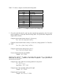
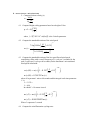
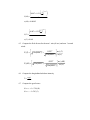
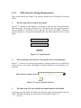
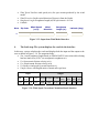
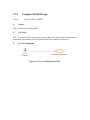
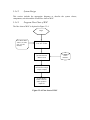
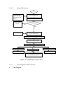
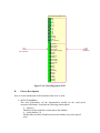
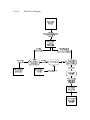
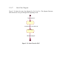
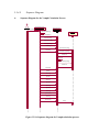
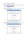
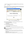
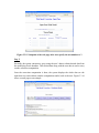
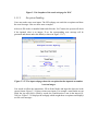
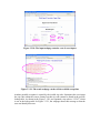
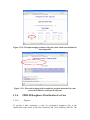
Florida Public Hurricane Loss Model
FPHLM
( Release V.2.6)
PRIMARY DOCUMENT BINDER
The Document
This binder contains a complete set of documents specifying the model structure, detailed
software description, and functionality.
Project Supervisors
Dr. Shu-Ching Chen
Associate Professor,
School of Computing and Information Sciences
Florida International University
Dr. Mei-Ling Shyu
Associate Professor,
Department of Electrical and Computer Engineering
University of Miami
Team Members
(Sort alphabetically)
Michael Armella
Ph. D. Student,
School of Computing and Information Sciences
Florida International University
Kasturi Chatterjee
Ph. D. Candidate,
School of Computing and Information Sciences
Florida International University
Shermann S. M. Chan
Post-Doc Scholar,
School of Computing and Information Sciences
Florida International University
Min Chen
(Student co-Leader)
Post-Doc Scholar,
School of Computing and Information Sciences
Florida International University
Fausto Fleites
Undergraduate Student,
School of Computing and Information Sciences
Florida International University
Lin Lin
Ph.D. Student,
Department of Electrical and Computer Engineering
University of Miami
Guy Ravitz
Ph.D. Candidate,
Department of Electrical and Computer Engineering
University of Miami
Khalid Saleem
Ph. D. Candidate,
School of Computing and Information Sciences
Florida International University
Zongxing Xie
MS. Candidate,
Department of Electrical and Computer Engineering
University of Miami
Na Zhao
(Student co-Leader)
Ph. D. Candidate,
School of Computing and Information Sciences
Florida International University
Table of Contents
VOLUME I. THE FLORIDA PUBLIC HURRICANE LOSS MODEL (FPHLM) ...................ERROR!
BOOKMARK NOT DEFINED.
1.1.
GENERAL DESCRIPTION OF FPHLM MODEL .........................ERROR! BOOKMARK NOT DEFINED.
1.2.
COMPUTER MODEL AND IMPLEMENTATION ..........................ERROR! BOOKMARK NOT DEFINED.
1.2.1. Use Case View of the System ................................................... Error! Bookmark not defined.
1.2.2. Network Diagram of the System .............................................. Error! Bookmark not defined.
1.3.
SYSTEM ARCHITECTURE DESIGN ..........................................ERROR! BOOKMARK NOT DEFINED.
1.3.1. Detailed System Architecture Design ...................................... Error! Bookmark not defined.
VOLUME III. STORM FORECAST MODULE (MODULE I) / WIND FIELD MODULE
(MODULE II) ...............................................................................ERROR! BOOKMARK NOT DEFINED.
3.1.
STORM TRACK MODEL USE CASE III ....................................ERROR! BOOKMARK NOT DEFINED.
3.1.1. General Description of Storm Track Model ............................ Error! Bookmark not defined.
3.1.2. Technical Description of the Storm Track Model.................... Error! Bookmark not defined.
3.1.2.1.
3.1.2.2.
3.1.2.3.
3.1.2.4.
3.1.2.5.
3.1.2.6.
3.1.3.
Rmax model................................................................................ Error! Bookmark not defined.
The empirical probability distribution generator (GENPDF)...... Error! Bookmark not defined.
The storm track generator (STORMGEN) .................................. Error! Bookmark not defined.
Appendix A – Wind-Pressure Relation ....................................... Error! Bookmark not defined.
Appendix B – Relative Intensity Calculation.............................. Error! Bookmark not defined.
Data Sources ............................................................................... Error! Bookmark not defined.
Computer Model Design & Implementation............................ Error! Bookmark not defined.
3.1.3.1.
3.1.3.2.
3.1.3.3
3.1.3.4
Use Case View of Storm Track Model ....................................... Error! Bookmark not defined.
Storm Track Model Implementation ........................................... Error! Bookmark not defined.
Program Flow Chart of Storm Track........................................... Error! Bookmark not defined.
Class Diagram and Description................................................... Error! Bookmark not defined.
3.1.4. References................................................................................ Error! Bookmark not defined.
3.2.
WIND FIELD MODEL USE CASE IV........................................ERROR! BOOKMARK NOT DEFINED.
3.2.1. General Description of Wind Field Model .............................. Error! Bookmark not defined.
3.2.2. General Requirements of Wind Field Model ........................... Error! Bookmark not defined.
3.2.3. Technical Description of Wind Field Model............................ Error! Bookmark not defined.
3.2.3.1.
3.2.3.2.
3.2.4.
Wind Model Parameters.............................................................. Error! Bookmark not defined.
Definitions and Equations of the wind model ............................. Error! Bookmark not defined.
Computer Model Design.......................................................... Error! Bookmark not defined.
3.2.4.1.
3.2.4.2.
3.2.4.3.
3.2.4.4.
3.2.4.5.
3.2.4.6.
Use Case View of Wind Speed Model........................................ Error! Bookmark not defined.
Detailed Flowchart...................................................................... Error! Bookmark not defined.
Class Diagram............................................................................. Error! Bookmark not defined.
Data Flow Diagram..................................................................... Error! Bookmark not defined.
Program Flow Chart of Wind Speed Model................................ Error! Bookmark not defined.
Glossary ...................................................................................... Error! Bookmark not defined.
3.2.5. References................................................................................ Error! Bookmark not defined.
3.3.
WIND SPEED CORRECTION (WSC) USE CASE V .......................................................................... 8
3.3.1. General Description Of WSC ................................................................................................. 9
3.3.2. WSC General Requirements ................................................................................................. 10
3.3.3. WSC Interface Design Requirements.................................................................................... 15
3.3.4. Computer Model Design....................................................................................................... 17
3.3.4.1.
3.3.4.2.
3.3.4.3.
3.3.4.4.
3.3.4.5.
3.3.4.6.
3.3.4.7.
3.3.4.8.
3.3.5.
Use Case View of WSC ............................................................................................................. 17
System Design ........................................................................................................................... 18
Program Flow Chart of WSC..................................................................................................... 18
Detailed Flowchart..................................................................................................................... 19
Class Diagram and Description.................................................................................................. 19
Data Flow Diagram.................................................................................................................... 22
State Chart Diagram................................................................................................................... 23
Sequence Diagram ..................................................................................................................... 24
Implementation of WSC ........................................................................................................ 26
3.3.5.1.
3.3.5.2.
3.3.5.3.
3.3.6.
Login page: ................................................................................................................................ 26
WSC Page:................................................................................................................................. 27
Exception Handling: .................................................................................................................. 30
FPHLM Roughness Classification Use Case ....................................................................... 32
3.3.6.1.
3.3.6.2.
3.3.6.3.
3.3.6.4.
Purpose ...................................................................................................................................... 32
Background................................................................................................................................ 33
References.................................................................................................................................. 33
FPHLM Land Cover - Roughness Classification ........................ Error! Bookmark not defined.
3.4.
WIND SPEED PROBABILITY (WSP) USE CASE VI..................ERROR! BOOKMARK NOT DEFINED.
3.4.1. General Description of WSP ................................................... Error! Bookmark not defined.
3.4.2. WSP General Requirements .................................................... Error! Bookmark not defined.
3.4.3. Computer Model Design.......................................................... Error! Bookmark not defined.
3.4.3.1.
3.4.3.2.
3.4.3.3.
3.4.3.4.
3.4.3.5.
3.4.3.6.
3.4.3.7.
3.4.3.8.
3.4.3.9.
3.4.4.
Use Case View of WSP .............................................................. Error! Bookmark not defined.
System Design ............................................................................ Error! Bookmark not defined.
Calculation of WSP..................................................................... Error! Bookmark not defined.
Class Diagram............................................................................. Error! Bookmark not defined.
Class Description ........................................................................ Error! Bookmark not defined.
Data Flow Diagram..................................................................... Error! Bookmark not defined.
State Chart Diagram.................................................................... Error! Bookmark not defined.
Sequence Diagram ...................................................................... Error! Bookmark not defined.
Program Flow Chart.................................................................... Error! Bookmark not defined.
Implementation of WSP ........................................................... Error! Bookmark not defined.
3.4.4.1.
3.4.4.2.
3.4.4.3.
3.4.4.4.
3.4.4.5.
Login page: ................................................................................. Error! Bookmark not defined.
WSP page:................................................................................... Error! Bookmark not defined.
WSP input selection .................................................................... Error! Bookmark not defined.
WSP results page ........................................................................ Error! Bookmark not defined.
Results of WSP ........................................................................... Error! Bookmark not defined.
VOLUME IV. DAMAGE ESTIMATION MODULE (MODULE III).......ERROR! BOOKMARK NOT
DEFINED.
4.1
MONTE CARLO SIMULATION MODEL (MCS) USE CASE I .....ERROR! BOOKMARK NOT DEFINED.
4.1.1
General Description of MCS ................................................... Error! Bookmark not defined.
4.1.2
MCS Design Requirements ...................................................... Error! Bookmark not defined.
4.1.3. Computer Model Design.......................................................... Error! Bookmark not defined.
4.1.3.1.
4.1.3.2.
4.1.4.2.1
4.1.4.2.2
4.1.4.2.3
4.1.4.3
Use Case View of MCS .............................................................. Error! Bookmark not defined.
System Design ............................................................................ Error! Bookmark not defined.
The MCS Driver ......................................................................... Error! Bookmark not defined.
MCS Damage Models................................................................. Error! Bookmark not defined.
MCS Common Files................................................................... Error! Bookmark not defined.
Implementation of Monte Carlo Simulation model..................... Error! Bookmark not defined.
4.2
VULNERABILITY AND FRAGILITY FOR RESIDENTIAL AND MANUFACTURED HOMES (VFRMH)
USE CASE II.........................................................................................ERROR! BOOKMARK NOT DEFINED.
4.2.1
General Description of VFRMH.............................................. Error! Bookmark not defined.
4.2.2
VFRMH Design Requirements ................................................ Error! Bookmark not defined.
4.2.3. Computer Model Design.......................................................... Error! Bookmark not defined.
4.2.3.1.
4.2.3.2
4.2.4
Home
Use Case View of VFRMH......................................................... Error! Bookmark not defined.
.System Design ........................................................................... Error! Bookmark not defined.
Implementation of Vulnerability and Fragility use case for Residential and Manufactured
Error! Bookmark not defined.
VOLUME V. INSURANCE LOSS MODULE (MODULE IV)ERROR! BOOKMARK NOT DEFINED.
5.1.
GENERAL DESCRIPTION OF ILM ...........................................ERROR! BOOKMARK NOT DEFINED.
5.2.
DETAILED DESIGN AND IMPLEMENTATION OF ILM ..............ERROR! BOOKMARK NOT DEFINED.
5.2.1. ILM Implementation Steps....................................................... Error! Bookmark not defined.
5.3.
COMPUTER MODEL DESIGN ..................................................ERROR! BOOKMARK NOT DEFINED.
5.3.1. Use Case View of Insurance Loss Model (ILM) ...................... Error! Bookmark not defined.
5.3.2. System Design of ILM.............................................................. Error! Bookmark not defined.
5.3.3. Class Diagram and Description .............................................. Error! Bookmark not defined.
5.3.4. Data Flow Diagram for ILM ................................................... Error! Bookmark not defined.
5.3.5. Sequence Diagram for ILM ..................................................... Error! Bookmark not defined.
5.3.6. Sequence Diagram for Scenario ILM ...................................... Error! Bookmark not defined.
5.4.
ADDITIONAL PROGRAMS .......................................................ERROR! BOOKMARK NOT DEFINED.
5.4.1. Generation of Combined Mobile Matrices .............................. Error! Bookmark not defined.
5.4.2. Application of Demand Surge.................................................. Error! Bookmark not defined.
5.5.
REFERENCES .........................................................................ERROR! BOOKMARK NOT DEFINED.
VOLUME VI. DATABASE DOCUMENT ................................ERROR! BOOKMARK NOT DEFINED.
6.1
SPECIFICATION FOR THE PROJECT .........................................ERROR! BOOKMARK NOT DEFINED.
6.2
DATA MODELING ..................................................................ERROR! BOOKMARK NOT DEFINED.
6.3
DESCRIPTION OF THE OBJECTS AND TABLES .........................ERROR! BOOKMARK NOT DEFINED.
6.4
DATA PROCESSING ................................................................ERROR! BOOKMARK NOT DEFINED.
6.4.1. Original Data Processing........................................................ Error! Bookmark not defined.
6.4.2. New Data Processing .............................................................. Error! Bookmark not defined.
6.5
DATA LOADING .....................................................................ERROR! BOOKMARK NOT DEFINED.
6.5.1. Original Data Loading ............................................................ Error! Bookmark not defined.
6.5.2
New Data Loading................................................................... Error! Bookmark not defined.
6.6
EXPORT AND IMPORT THE DATA ...........................................ERROR! BOOKMARK NOT DEFINED.
6.7
MAINTENANCE TASK FOR EACH HURRICANE SEASON ............ERROR! BOOKMARK NOT DEFINED.
6.8
DATA CHECKING ...................................................................ERROR! BOOKMARK NOT DEFINED.
6.9
QUERIES ................................................................................ERROR! BOOKMARK NOT DEFINED.
6.9.1. Change the Query Based on the New Schema ......................... Error! Bookmark not defined.
6.10
DATABASE TUNING ...............................................................ERROR! BOOKMARK NOT DEFINED.
6.10.1.
Tuning SQL Statements....................................................... Error! Bookmark not defined.
6.10.2.
The Goals of SQL Tuning ................................................... Error! Bookmark not defined.
6.10.3.
Using the Timing Environments Parameter........................ Error! Bookmark not defined.
6.10.4.
Using SQL Trace and TKPROF.......................................... Error! Bookmark not defined.
VOLUME VII. FPHLM QUALITY ASSURANCE..................ERROR! BOOKMARK NOT DEFINED.
7.1.
CODING GUIDE LINES ...........................................................ERROR! BOOKMARK NOT DEFINED.
7.1.1. About the Coding Guidelines................................................... Error! Bookmark not defined.
7.1.2. File Organization .................................................................... Error! Bookmark not defined.
7.1.2.1.
7.1.2.2.
7.1.3.
Code Indentation ..................................................................... Error! Bookmark not defined.
7.1.3.1.
7.1.3.2.
7.1.4.
Simple Statements....................................................................... Error! Bookmark not defined.
Return Statements ....................................................................... Error! Bookmark not defined.
If, if-else, if else-if else Statements ............................................. Error! Bookmark not defined.
For Statements ............................................................................ Error! Bookmark not defined.
While Statements ....................................................................... Error! Bookmark not defined.
Try-catch Statements................................................................... Error! Bookmark not defined.
White Space ............................................................................. Error! Bookmark not defined.
7.1.7.1.
7.1.7.2.
7.1.8.
Number of Declarations per Line................................................ Error! Bookmark not defined.
Initialization ................................................................................ Error! Bookmark not defined.
Statements................................................................................ Error! Bookmark not defined.
7.1.6.1.
7.1.6.2.
7.1.6.3.
7.1.6.4.
7.1.6.5.
7.1.6.6.
7.1.7.
Block Comments......................................................................... Error! Bookmark not defined.
Single Line Comments................................................................ Error! Bookmark not defined.
In line File Documentation.......................................................... Error! Bookmark not defined.
In line Function Documentation.................................................. Error! Bookmark not defined.
Variable Declarations ............................................................. Error! Bookmark not defined.
7.1.5.1.
7.1.5.2.
7.1.6.
Wrapping Lines........................................................................... Error! Bookmark not defined.
White Spaces: Don't use spaces for indentation - use tabs!........ Error! Bookmark not defined.
Comments ................................................................................ Error! Bookmark not defined.
7.1.4.1.
7.1.4.2.
7.1.4.3.
7.1.4.4.
7.1.5.
Source files ................................................................................. Error! Bookmark not defined.
Directory Layout......................................................................... Error! Bookmark not defined.
Blank Lines ................................................................................. Error! Bookmark not defined.
Inter-term spacing ....................................................................... Error! Bookmark not defined.
Naming Conventions................................................................ Error! Bookmark not defined.
7.1.8.1.
7.1.8.2.
Naming Guidelines ..................................................................... Error! Bookmark not defined.
Variable Names........................................................................... Error! Bookmark not defined.
7.1.8.3.
7.1.8.4.
Method Names ............................................................................ Error! Bookmark not defined.
Model Names .............................................................................. Error! Bookmark not defined.
7.1.9. Reference ................................................................................. Error! Bookmark not defined.
7.2.
DATA VALIDATION AND VERIFICATION ................................ERROR! BOOKMARK NOT DEFINED.
7.2.1. Introduction ............................................................................. Error! Bookmark not defined.
7.2.1.1.
7.2.1.2.
Data Verification......................................................................... Error! Bookmark not defined.
Data Validation ........................................................................... Error! Bookmark not defined.
7.2.2. Procedures............................................................................... Error! Bookmark not defined.
7.2.3. Data Security and Integrity ..................................................... Error! Bookmark not defined.
7.2.4. References................................................................................ Error! Bookmark not defined.
7.3.
MODEL MAINTENANCE AND REVISION .................................ERROR! BOOKMARK NOT DEFINED.
7.3.1. Model Maintenance and Revision............................................ Error! Bookmark not defined.
7.4. FPHLM TESTING PROCEDURES ....................................................ERROR! BOOKMARK NOT DEFINED.
7.4.1. Software Testing Procedures................................................... Error! Bookmark not defined.
7.5.
CODE COUNT TABLES ...........................................................ERROR! BOOKMARK NOT DEFINED.
VOLUME VIII. SECURITY .......................................................ERROR! BOOKMARK NOT DEFINED.
8.1.
8.2.
SECURITY PROCEDURES ........................................................ERROR! BOOKMARK NOT DEFINED.
FIU SCS COMPUTER AND NETWORKING SECURITY PROCEDURES MANUAL ERROR! BOOKMARK
NOT DEFINED.
8.3.
FIU SCS HURRICANE PREPARATION PROCEDURES:..............ERROR! BOOKMARK NOT DEFINED.
8.4.
NON-DISCLOSURE AGREEMENT ............................................ERROR! BOOKMARK NOT DEFINED.
VOLUME IX. SYSTEM HARDWARE AND SOFTWARE CONFIGURATIONS ..................ERROR!
BOOKMARK NOT DEFINED.
9.1.
9.2.
9.3.
9.4.
SYSTEM ARCHITECTURE .......................................................ERROR! BOOKMARK NOT DEFINED.
SOFTWARE LIST ....................................................................ERROR! BOOKMARK NOT DEFINED.
HARDWARE CONFIGURATION ...............................................ERROR! BOOKMARK NOT DEFINED.
SAFETY AND BACKUPS ..........................................................ERROR! BOOKMARK NOT DEFINED.
VOLUME X. TRAINING PLAN ................................................ERROR! BOOKMARK NOT DEFINED.
9.1.
TESTING TEAM TRAINING PLAN............................................ERROR! BOOKMARK NOT DEFINED.
VOLUME XI. HUMAN RESOURCES......................................ERROR! BOOKMARK NOT DEFINED.
VOLUME XII. FPHLM RELATED PUBLICATIONS ...........ERROR! BOOKMARK NOT DEFINED.
VOLUME XIII. USER MANUAL ..............................................ERROR! BOOKMARK NOT DEFINED.
VOLUME XIV. TEST REPORT ................................................ERROR! BOOKMARK NOT DEFINED.
3.3.
Wind Speed Correction (WSC)
Use Case V
3.3.1.
General Description Of WSC
WSC, shorts for Wind Speed Correction, is the fifth use case of the Florida Hurricane
Loss Model. It aims at refining open terrain wind speed produced by the hurricane wind
model with respect to the actual terrain (based on land use – land cover).
3.3.2.
WSC General Requirements
Name:
Wind Speed Correction
Description: The inputs are zip code, surface wind speed for open terrain
produced by the wind model, surface wind direction, and
roughness length for open terrain. The system generates the
following:
(1) Surface wind speed for actual terrain (m/s).
(2) 10-minute sustained wind speed for actual terrain (mph).
(3) 3-Second gust wind speed for actual terrain (mph).
1. Following are the input data:
Zip: Zip Code
Vo: Surface Wind Speed for open terrain produced by the wind model (m/s)
WD: Surface Wind Direction (Deg from North)
Zoo: Roughness Length (m) for open terrain = 0.03m
Zoa: Roughness length based on upstream terrain
Lat: Latitude
2. Based on the input data from step 1, the system queries the database and returns Zoa
parameter, which corresponds to the actual roughness length based on FEMA
HAZUS conversion table relating land use-land cover (LULC) to aerodynamic
roughness (m). Roughness represents a weighted average of all roughness pixels
within a 45-degree sector with origin at the population-weighted centroid of the zip
code and extending outward to 20 km from the centroid. The weighting function for
averaging the roughness values is a Gaussian filter with a half power point at 3 km.
The format of the lookup table is as following:
Zip
Lon
Lat
Zo1
Zo2
Zo3
Zo4
Zo5
Zo6
Zo7
Where:
Zo1 = Actual Roughness for wind directions inclusive of 46-90
Zo2 = Actual Roughness for wind directions inclusive of 1-45
Zo3 = Actual Roughness for wind directions inclusive of 316-0, 360
Z04 = Actual Roughness for wind directions inclusive of 271-315
Z05 = Actual Roughness for wind directions inclusive of 226-270
Zo6 = Actual Roughness for wind directions inclusive of 181-225
Zo7 = Actual Roughness for wind directions inclusive of 136-180
Zo8 = Actual Roughness for wind directions inclusive of 91-135
Zo8
Table 3.3.1 shows a sample record from the lookup table.
Zip
Lon
Lat
Zo1
Zo2
Zo3
Zo4
Zo5
Zo6
Zo7
Zo8
33172
80.358246
25.775768
.254
.277
.333
.253
.297
.274
.287
.281
Table 3.3.1: A sample record for the lookup table
3. Given the wind direction for each zip code centroid, the appropriate value for actual
terrain roughness is extracted from the lookup table. The system then computes the
output values as below:
Compute open terrain friction velocity Uo (Unit: m/s):
Uo = Vo * 0.4 / [ Ln (10.0 / 0.03 ) ]
Compute actual terrain friction velocity Ua (Unit: m/s, using equation 3 of Powell et
al., 1996)
Ua = Uo / ( [Zoo / Zoa] ^ 0.0706 )
Compute actual terrain wind speed at 10 m Va:
Va = ( Ua / 0.4 ) ( Ln (10 / Zoa ) )
Convert wind speed to the unit of MPH:
Vamph = Va * 2.2369
Compute gust factors for peak 1 min wind over 10 min G10min,60 and peak 3s
wind over 10 min G10min,3 based on the actual roughness. [See gust factor
calculations below]
Compute max 1 min wind (m/s) occurring within 10 min period
V1 = Va * G10min,60
ZipOTWS1 = Va * 1.142
Compute max 1 min sustained wind speed in mph
V1mph = V1 * 2.2369
Compute peak 3s gust in mph
V3mph = Va * G10min,3 * 2.2369
4. Gust factor calculations
2. Compute friction velocity (u)
0.4Va
u= ⎛
⎞
⎜ 10 ⎟
⎟
Ln⎜
⎜ Zoa ⎟
⎠
⎝
4.1. Compute Height scaling parameter based on a height of 10 m
⎛ 10 ⎞
⎟
⎝u⎠
η =1− 6 f ⎜
where f = 2(7.292 *10−5 sin(Lat )) is the Coriolis parameter
4.2. Compute the standard deviation of the wind speed
⎛
⎜
⎜
⎜
⎜
⎜⎜
⎝
⎞η
⎟
⎛ 10 ⎞
⎟
7.5ηu 0.09 Ln⎜
⎟ + 0.538 ⎟⎟⎟
⎟
⎝ Zoa ⎠
⎠
σu ( z ) =
⎛
⎛ u ⎞⎞
⎜1 + 0.156 Ln⎜
⎟ ⎟⎟
⎜
f
.
Zoa
⎝
⎠⎠
⎝
16
4.3. Compute the standard deviation of the low-pass filtered wind speed
considering a filter with a cut-off frequency of 1 cycle per 3 seconds (for the
peak 3s gust) and 1 cycle per 60 seconds (for the maximum 1 min sustained
wind speed calculation:
− 0 .68
⎞
⎛
t
I
⎛
⎞
⎟
σu ( z ,60 ) = σu ( z ) ⎜⎜ 1 − 0 .193 ⎜ + 0 .1 ⎟
⎟
60
⎝
⎠
⎠
⎝
σu ( z ,60 ) = 0 .386762 σu ( z )
where 60 represents 1 min or 60 seconds and the integral scale time parameter
It is,
It = 3.13Z 0 2
It = 4.96
In which Z = 10 meters is used.
−0.68
⎞
⎛
⎛ It
⎞
⎜
σu ( z,3) = σu ( z )⎜1 − 0.193⎜ + 0.1⎟ ⎟⎟
⎝3
⎠
⎠
⎝
σu ( z,3) = 0.868256421σu ( z )
Where 3 represents 3 seconds
4.4. Compute the wind fluctuation cycling rates:
⎛
⎛ It ⎞ 0 654 ⎞
⎜⎜ 0.007 + 0.213⎜ ⎟ ⎟⎟
⎝ 60 ⎠ ⎠
⎝
Cr(60) =
It
Cr(60) = 0.00982
⎛
⎛ It ⎞ 0 654 ⎞
⎜⎜ 0.007 + 0.213⎜ ⎟ ⎟⎟
⎝ 3⎠ ⎠
⎝
Cr(3) =
It
Cr(3) = 0.061
4.5. Compute the Peak factors for the max 1 min (60 sec) and max 3 second
winds
⎡
⎤ σu ( z ,3)
0.557
Pf (3) = ⎢ 2 Ln(600Cr ) +
⎥
2 Ln(600Cr ) ⎦⎥ σu ( z )
⎣⎢
⎡
⎤ σu ( z,60)
0.557
Pf (60) = ⎢ 2 Ln(600Cr ) +
⎥
(
2
600
r)
Ln
C
⎣
⎦ σu ( z )
4.6. Compute the longitudinal turbulent intensity
Til =
σu(z)
Uh
4.7. Compute the gust factors:
G10 min,60 = 1 + TilPf (60)
G10 min,3 = 1 + TilPf (3)
A sample calculation is as follows:
Input
Zip = 33133
Vo = 50 m/s
WD = 60
Zoo = 0.03
Lat = 25.73
Lookup value
Zoa = 0.431 m
Output
Uo = 3.44 m/s, Ua = 4.16 m/s, Va = 32.66
m/s, V1mph = 90.08 mph, V3mph = 123.55
mph
3.3.3.
WSC Interface Design Requirements
This section presents the Graphic User Interface design for the Wind Speed Correction
(WSC).
1.
The first step: the user logs in the system
Figure 3.3.1 shows the Login Interface. User needs to enter the user id and password to
enter the system. The system verifies the user’s information with the login data extracted
from the database. If it matches, the user logs into the system successfully. Otherwise,
system displays the “wrong user name/password” error and requests the user to login
again.
F D O IU S E R
U serID :
P a ssW D :
*** * ** * *
L O G IN
Figure 3.3.1: Login Interface
2.
The second step: select the use case from the service selection page
Figure 3.3.2 is the service selection page interface. System presents a list of available use
cases to the user. User selects “Wind Speed Correction Model” use case and clicks “Go”
to submit.
Please choose an online service:
-------------------------------------
Go
Figure 3.3.2: Service Selection Interface
3.
The third step: The user provides the input from the wind model
In this step, system provides the interface for the user to input data generated by the wind
model. The following inputs are required and are illustrated by Figure 3.3.3:
• Zip code:
•
Wind Speed: Surface wind speed (m/s) for open terrain produced by the wind
model.
Wind Direction: Surface wind direction (Degree(s) from the North).
Roughness Length: Roughness length (m) for open terrain = 0.03 m.
Latitude:
•
•
•
Num
Wind Speed
(m/s)
Zip Code
Wind
Direction
Roughness
length (m)
Latitude (deg)
1
Figure 3.3.3: Input from Wind Model Interface
4.
The forth step: The system displays the result in the interface
In this step, system calculates the result and displays both the input and the output to the
user as shown in Figure 3.3.4. The output includes:
• Zoa: Actual roughness length based on FEMA HAZUS conversion table relating
land use land cover (LULC) to aerodynamic roughness (m).
• Uo: Open terrain friction velocity (m/s).
• Ua: Actual terrain friction velocity (m/s).
• Va: Surface wind speed for actual terrain (m/s).
• Vamph: Above with English units of statute miles per hour.
Input
Output
Zip
Vo
(m/s)
Wd
Zoo Zoa (m) Uo (m/s) Ua (m/s)
33133
50.0
60
0.03
0.431
3.44
4.16
Va Vamph V1mph V3mph
(m/s) (mph) (mph) (mph)
32.66 73.17 90.08 123.55
Figure 3.3.4: Wind Speed Correction Calculation Result Interface
3.3.4.
3.3.4.1.
A.
Computer Model Design
Use Case View of WSC
Actors:
There is one actor, scientist in WSC.
C.
Use Case:
WSC is used to convert open terrain winds produced by the hurricane wind model to
winds more representative of the actual terrain (based on land use- land cover).
C.
Use Case Diagram:
Scientist
W indSpeedCalUseCase
Figure 3.3.5: Use Case Diagram for WSC
3.3.4.2.
System Design
This section includes the appropriate diagrams to describe the system classes,
components, activities and the overall flow chart of WSC.
3.3.4.3.
Program Flow Chart of WSC
The flow chart of WSC is depicted in Figure 3.3.6.
Begin
User Enters Data
Values (Vo, WD,
Zoo, zip, and
latitude)
System displays form
to the user for data
System connects and
gets data from the
database (Zoa)
System performs
calculations (Vamph,
V1mph, V3mph)
System displays
results to the user
and/or produces
output file
Figure 3.3.6: Flow chart of WSC
Oracle
Database
3.3.4.4.
Detailed Flowchart
Start
System displays form to the
user for inputting data
User Enters Data
Values (Vo, WD,
Zoo, zipcode, and
latitude)
Display related
message
Read and Check the input data
Valid input?
No
Yes
Oracle data base
System connects and gets data
from the database (Zoa)
Calculate Guest factor (G10min,60 and G10min,3)
System performs calculations
(Vamph, V1mph, V3mph)
Calculate parameters Uo, Ua, and Va
V1 = Va * G10min,60
Vamph = Va * 2.2369
V1mph = V1 * 2.2369
V3mph = V3 * 2.2369
System displays results to the user
and/or produces output file
Figure 3.3.7: Detailed Flow chart of WSC
3.3.4.5.
A.
Class Diagram and Description
Class Diagram
V3 = Va * G10min,3
W S CCalV am phB ean.java
z ip []
lat i []
V o []
W D []
Zo o [ ]
Zo a [ ]
Uo []
Ua []
V a []
V 1 []
V 3 []
V am ph []
V 1m ph []
gs t60 []
Gus t _Fac t or()
c o nnec t ()
dis c on nect()
c a lc Gus t ()
c a lV am ph()
ge tRoughn es _def()
fi ndCol()
ge tZo()
qu ery Zo a()
ge tZoa()
ge tV am ph()
ge tV 1m ph()
ge tV 3m ph()
ge tUa()
ge tUo()
ge tV a()
ge tV 1()
ge tgs t 60( )
s e tLat ()
s e tZi p()
s e tV o()
s e tZoa()
s e tW D()
s e tZoo()
JS P interfac e
Databas e
Figure 3.3.8: Class Diagram for WSC
B.
Classes Descriptions
Here is a brief introduction of the functions in the class we used.
¾ WCSCalVamphBean
This class performance all the functionalities needed for the wind speed
correction calculation. It includes the following main methods:
• connect()
Method is used to establish a connection to the database
• setLat (double [] l)
Method takes an array of doubles and sets the latitude array to the passed
array
• setZip(int [] z)
Method takes an array of integers and sets the zip array to the passed array
• setVo(double [] z)
Method takes an array of doubles and sets the Vo array to the passed array
• setWD(int [] w)
Method takes an array of integers and sets the WD array to the passed array
• setZoo(double [] z)
Method takes an array of doubles and sets the Zoo array to the passed array
• queryZoa()
Uses the connection to the database to send a query and retrieve the value for
Zoa based on the zip and the returned string value from a call to the findCol
method.
• calVamph()
Method is used to calculate the Vamph, Va, Uo and Ua using the following
input values from the user Vo, Zoo and Zoa
• calcGust()
Method is used to calculate the gust factors G10min,60 and G10min,3 using the
following input values Lat, WD, Zoa and Va
• GetRoughness_def()
Method uses the established connection to the database to find and return the
column names and starting and ending degrees corresponding to each column
of the roughness_def table.
• findCol(int wd)
Method takes a wind direction (WD) as a parameter. It uses the established
connection to the database to find and return the correct string, using the WD,
which represents the column in the lookup table for Zoa.
• get Zoa()
Return the value of Zoa
• getVamph()
Return the value of Vamph
• getV1mph()
Return the value of V1mph
• getV3mph()
Return the value of V3mph
• getUa()
Return the value of Ua
• getUo()
Return the value of Uo
• getVa()
Return the value of Va
• disconnect()
Method is used to disconnect from the database
3.3.4.6.
Data Flow Diagram
3.3.4.7.
State Chart Diagram
Figure 3.3.8 depicts the state chart diagram for Use Case Five. This diagram illustrates
states that the use case goes through from beginning to end.
Page requested
Idle
mouseClicked / User data sent
Processing
Results Displayed
Figure 3.3.9: State Chart for WSC
3.3.4.8.
A.
Sequence Diagram
Sequence Diagram for the Vamph Calculation Process
: Scientist
WindSpeedCal.jsp
WSCCalVamph
Bean.java
Page Requested
setParameter(string)
Database
setZip(int [])
setVo(double [])
setWD(double [])
setZoo(double [])
connect()
getConnection(string)
queryZoa()
executeQuery(String)
Result Set
findCol(int)
executeQuery(string)
Result Set
calVamph()
getZoa()
double []
getUo()
double []
getUa()
double []
getVa()
double []
getVamph()
double []
disconnect()
close()
Figure 3.3.10: Sequence diagram for Vamph calculation process
B.
Sequence Diagram Steps for the Vamph Calculation Process
•
Step 1: The user requests the html page
•
Step 2: The user enters the number of data sets to be calculated
•
Step 3: The user inputs data for zip code, Vo, WD and Zoo and they are
passed to the WSCCalVamphBean object
•
Step 4: WindSpeedCalc.jsp requests WSCCalVamphBean object to establish
a connection to the database
•
Step 5: WSCCalVamphBean establishes a connection to the database
•
Step 6: WindSpeedCalc.jsp requests WSCCalVamphBean to query the
database based on data passed from JSP
•
Step 7: WSCCalVamphBean queries the database which returns a ResultSet
to the BEAN
•
Step 8: WSCCalVamphBean calls its findCol method.
•
Step 9: WSCCalVamphBean queries the database which returns a ResultSet
to the BEAN
•
Step 10: WindSpeedCalc.jsp requests to perform Vamph calculations.
•
Step 11: WindSpeedCalc.jsp requests the results for Zoo, Uo, Ua, Va and
Vamph and WSCCalVamphBean returns the required data.
•
Step 12: WindSpeedCalc.jsp notifies that it is okay to close the database
connection
•
Step 13: WSCCalVamphBean closes the database connection
3.3.5.
Implementation of WSC
Currently, the implementation for Use Case five (WSC) has been finished. The demo is
reachable at http://www.cs.fiu.edu/PHRLM.
3.3.5.1.
Login page:
Users need username/password to access the Florida Hurricane Loss Model. Following is
a snapshot of the login web page.
Figure 3.3.11. Login webpage for FPHLM
If the username/password is wrong, an error message will be displayed. User will be
required to input the username and password again to enter.
Figure 3.3.12. Login webpage shows the inputted user ID or password is wrong
3.3.5.2.
WSC Page:
If the login is successful, the user can see the web page named “Service Selection Page”
(as shown in Figure 3.3.13). To view the WSC use case page, from the drop-down list,
select “Wind Speed Correction” and click “Go” button.
Figure 3.3.13. Service selection page for WSC
Several steps need to be followed to accomplish the task of Wind Speed Correction,
User can select two input methods.
a. Input from file (this is the use case four output)
b. Manual Input
If user wants to take the input from file
1. Click on ‘From File’ radio button
2. Select the input data set from an available data set
3. Click on ‘submit’
If the user wants to enter the input manually, first click on ‘Manual Input’ radio button.
Step 1:
Then, the users need to input the wind field data fields. Input data sets from the wind
model include the following fields:
• Zip: Zip code
• Vo: Surface wind speed for open terrain produced by the wind model (m/s)
• Wd: Surface wind direction (Deg from North). The data range for this field is
from 0 to 360.
• Zoo: Roughness length (m) for open terrain = 0.03 m
• Latitude: Latitude of the corresponding zip code. (a value between 20 and 40)
A data input page is provided to facilitate users to input the corresponding data easily.
Users are allowed to input a variety of collections of input data and submit this data for
wind speed correction calculation.
By default, the number of input data sets is one. So initially, there is only one set of blank
control for the user to input his/her data. Figure 3.3.14 illustrates the snapshot of the
dataset input page for wind speed calculation.
Figure 3.3.14. Snapshot of the first web page for WSC
To input more than one set of input data, the user can change the number of input data
sets by using the “number of sets change“ option provided at the top of the dataset input
page. The user inputs the desired number of data sets in the blank after “How many
sets?”, and then clicks “Set” button. Figure 3.3.15 shows an example dataset input web
page after the user requests three sets of input data.
Figure 3.3.15. Snapshot of the web page after user specify the sets number to 3
Step 2:
Secondly, the system constructs a query using the user’s data to obtain desired data from
the underlying Oracle database. This desired data along with the user data is used to carry
out the correction computation.
Once the correction computation is done, the system displays the whole data set: the
input data set, retrieved data, and the computation results, back to the user. Figure 3.3.16
shows a result page as an example.
Figure 3.3.16: Snapshot of the result web page for WSC
3.3.5.3.
Exception Handling:
Users may make some error inputs. The JSP webpage can catch the exceptions and show
the error messages. Here we show some examples:
After user fills in the set number blank and clicks the “Set” button, the system will check
if the inputted value is an integer. If no, the corresponding error message will be
generated and shown under this blank (as shown in Figure 3.3.17).
Figure 3.3.17. The input webpage shows the exception that the inputted set number
is not an integer.
User needs to follow the instructions, fill in all the blanks and input the data sets in the
correct format. Figure 3.3.18 shows some error inputs. For example: some blanks are not
filled; the zip code field is filled by words; the wind direction is not in the interval [0,
360]; etc. Figure 3.3.19 displays the webpage which caught these exceptions and displays
several error messages.
Figure 3.3.18: The input webpage contains a set of error inputs
Figure 3.3.19: The result webpage catches all the available exceptions
Another possible exception is caused by the invalid zip code. Sometimes the user inputs
the zip code within the correct format, but this zip code cannot be found in the specific
lookup table. As shown in the Figure 3.3.20, user inputted a zip code as “12345”, which
is not in the lookup table. In Figure 3.3.21, the webpage shows this message so that the
user can identify this error.
Figure 3.3.19: The input webpage contains a Zip code value which is not included in
the lookup table
Figure 3.3.21: The result webpage which caught the exception when the Zoa value
can not be fetched for some specific Zip code
3.3.6.
3.3.6.1.
FPHLM Roughness Classification Use Case
Purpose
To provide a table associating a value for aerodynamic roughness (Zo) to the
classification codes listed in the 2001 National Land Cover Database (NLCD). The
NLCD is developed from Landsat 7 imagery Multi-Resolution Land Characteristics
Consortium (MRLC) http://www.mrlc.gov/ The 2001 NLCD data will replace the circa
1994-1995 roughness obtained from FEMA’s Hazus model that was used in FPHLM
versions 2.5 and earlier.
3.3.6.2.
Background
The classification codes are listed at (http://www.mrlc.gov/nlcd_definitions.asp).
For codes whose descriptions are identical to the roughness classification table listed in
the 2003 Hazus Technical Users manual, we leave the values unchanged. For new
classifications, we use example images from NOAA’s Coastal Services Center to
estimate roughness based on field experience evaluating roughness from weather station
site visits and aerial/satellite imagery for post-storm hurricane wind field reconstruction
(see references). The code for determining roughness from NLCD data was written and
implemented by Steve Cocke and is described in Axe 2003.
3.3.6.3.
References
Coastal NLCD Classification Scheme
http://www.csc.noaa.gov/crs/lca/tech_cls.html - 17
NLCD Land Cover Classification definitions
http://www.mrlc.gov/nlcd_definitions.asp
Axe, L. 2003: Hurricane surface wind model for risk management. Masters thesis,
Department of Meteorology, Florida State University, 68 pp.
Homer, C. C. Huang, L. Yang, B. Wylie and M. Coan. 2004. Development of a 2001
National Landcover Database for the United States. Photogrammetric Engineering and
Remote Sensing, Vol. 70, No. 7, July 2004, pp. 829-840.
Powell, M.D., D. Bowman, D. Gilhousen, S. Murillo, N. Carrasco, and R. St. Fleur,
2004: Tropical Cyclone Winds at Landfall: The ASOS-CMAN Wind Exposure
Documentation Project. Bull. Amer. Met. Soc., 85, 845-851.
Powell, M. D., S. H. Houston, L. R. Amat, and N Morisseau-Leroy, 1998: The HRD
real-time hurricane wind analysis system. J.Wind Engineer. and Indust. Aerodyn. 77&78,
53-64.
Powell, M. D., S. H. Houston, and T. A. Reinhold, 1996: Hurricane Andrew's Landfall
in South Florida. Part I: Standardizing measurements for documentation of surface wind
fields. Weather Forecast., 11, 304-328.