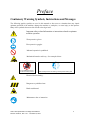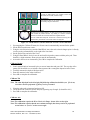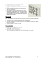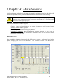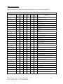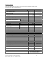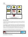
1
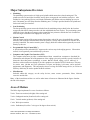
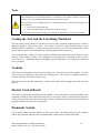
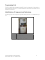
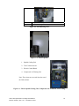
Helix 5-Axis
Ophthalmic Lens Edger
User Manual
November 5, 2010
Part No. 87406-11, Rev. 1.01
Helix 5-Axis Ophthalmic Lens Edger User Manual
Part No. 87406-11, Rev. 1.01 - November 5, 2010
2
Table of Contents
Page No.
Preface
5
Chapter 1: The Helix Edger
9
Chapter 2: Operation
19
Chapter 3: Calibration
43
Chapter 4: Maintenance
49
Appendix A: General Specifications
53
Appendix B: Certification & Standards
55
Appendix C: Electrical Diagram
59
Appendix D: Certificate of Compliance
61
Helix 5-Axis Ophthalmic Lens Edger User Manual
Part No. 87406-11, Rev. 1.01 - November 5, 2010
3
Helix 5-Axis Ophthalmic Lens Edger User Manual
Part No. 87406-11, Rev. 1.01 - November 5, 2010
4
Preface
Cautionary Warning Symbols, Instructions and Messages
The following graphic symbols are used in this manual to alert users to situations that may impair
optimum operation of the machine, damage the machine or workpiece, or cause injury to the operator.
Many of the symbols shown are also affixed to the edger itself.
Important safety-related information or instructions related to optimum
machine operation.
Wear protective gloves.
Wear protective goggles.
Indicated operation is prohibited.
Mechanical hazard or advisory. See examples below:
It is prohibited to remove
or alter the safety devices
Assure safety devices are working correctly before starting work
Electrical shock warning .
Dangerous or prohibited area.
Hand-crush hazard.
Maintenance alert or instruction.
Helix 5-Axis Ophthalmic Lens Edger User Manual
Part No. 87406-11, Rev. 1.01 - November 5, 2010
5
This document is based on information available at the time of its publication. While efforts have been made
to be accurate, the information contained herein does not purport to cover all details or variations in hardware
or software, nor to provide for every possible contingency in connection with installation, operation, or
maintenance. The manufacturer assumes no obligation of notice to holders of this document with respect to
changes subsequently made.
Safety First
Observe the following precautions to minimize the risk of accidents or injury. Other important safety
information appears elsewhere in this manual. Item #1 below is important.
1. Read and understand this manual before operating the equipment. If you do not understand the
instructions, consult your supervisor or a service representative.
2. Assure that the installation instructions have been followed and that the electrical and pneumatic
connections have been made as required.
3. Before turning on the equipment, visually verify that there are no foreign objects in the cutting area
that may impede the machine motion.
4. Assure that all coolant and lubrication reservoirs are filled, and all filters are clear of obstruction.
5. Do not open any part of the cabinet unless you are certain that no cycle is in progress and all machine
motion has completely stopped.
6. Do not attempt to bypass any of the safety interlocks for the door or case-top.
7. Do not attempt to operate the machine unless all cabinet access points are closed.
8. Never attempt to machine a glass lens. The Helix edger is intended only for machining resin (plastic)
ophthalmic lenses.
9. Perform maintenance as indicated in this manual. Clean the cutting area regularly.
10. When performing maintenance or repair operations, be sure to follow all safety instructions, such as
removing electrical power, as described in this manual.
Safety Interlocks
The Helix edger has been equipped with a large number of interlocks to block or stop machine operation
if some anomalous or unsafe condition is detected. These interlocks must be checked as part of the
periodic maintenance, and must never be defeated except by trained personnel during certain maintenance
operations.
It is prohibited to remove
or alter the safety devices
Assure safety devices are working
correctly before starting work
Helix 5-Axis Ophthalmic Lens Edger User Manual
Part No. 87406-11, Rev. 1.01 - November 5, 2010
6
The manufacturer and seller hereby disclaim any liability in the following cases:
•
•
•
•
•
•
•
Improper use of the machine.
Use of the machine by unauthorized staff.
Incorrect installation, unless such installation was performed by the manufacturer or seller.
Unsuitable energy and fluid supplies.
Lack of maintenance.
Unauthorized modifications and installations.
Use of non-original spare parts or parts that do not correspond to the manufacturer's specifications.
Refer to Chapter 4 for detailed maintenance instructions. Refer to Appendix B for descriptions of the
standards to which Helix edgers comply applicable agency certifications and listings in effect. The user’s
attention is particularly directed towards the discussion of residual risks from operating the machine.
Helix 5-Axis Ophthalmic Lens Edger User Manual
Part No. 87406-11, Rev. 1.01 - November 5, 2010
7
Helix 5-Axis Ophthalmic Lens Edger User Manual
Part No. 87406-11, Rev. 1.01 - November 5, 2010
8
Chapter 1: The Helix Edger
General Description
The Helix edger is a device comprising mechanical, electrical, pneumatic and software elements whose
function is the precise machining of resin ophthalmic lenses. This includes edging with a large variety of
contours, drilling and milling. The Helix is equipped with a tool-changing mechanism that permits all such
operations to be performed without the user needing to manually change tools or remount the work piece.
Additional flexibility is achieved via five primary axes of motions, including tilting the axis of rotation of the
work piece. This allows, for example, very high-wrap lenses to be dynamically beveled or grooved, and
complex shelf cuts to be made.
The Helix is contained within a single floor-standing cabinet, mounted on casters so that it may be easily
repositioned for access to all points within the cabinet. The top-front of the cabinet swings up to open for
maintenance access to the machining area. A smaller door in the center-front of the unit opens/closes
vertically to allow insertion or retrieval of the lens, or access to the tool store. The touch screen display is
above the door. The back of the Helix cabinet has two removable panels and an access door on the lower
panel permitting user access to fluid reservoirs, filters, and other components.
All doors and access panels must be closed in order for any motion in the machining area to occur.
Installation
Installation of the Helix is normally included in the sales conditions and is therefore performed by
personnel authorized by the machine supplier.
Transport and Handling
The machine weighs about 360kg.
The machine may be moved in the following cases:
•
•
Loading or unloading from the means of transport.
Movement inside a lab or production facility.
In the loading and unloading operations, the machine must be lifted using a fork-lift truck. The fork must
be adjusted in a way to be inserted into the designated lift points.
The machine is mounted on casters, allowing movement on flat, smooth surfaces. The rear wheels are
fixed and the front ones swivel and can be blocked.
The manufacturer is not responsible for any damage due to incorrect handling.
Helix 5-Axis Ophthalmic Lens Edger User Manual
Part No. 87406-11, Rev. 1.01 - November 5, 2010
9
Positioning
The Helix must be installed so that a space is left behind the cabinet to allow the inspection of the parts
located in the rear of the machine. These require periodic maintenance to guarantee optimal operation of
the machine over time.
Unpacking
The machine should be unpacked as close as possible to its final operating location. This reduces the
likelihood of damage caused by vibration and jarring while moving the machine.
Do not use sharp tools to remove packaging materials to avoid marring or damaging the machine.
Connections to Sources of Energy
Do not connect the Helix to external energy sources until it has been correctly positioned. The following
connections are necessary:
•
•
Electricity
Compressed Air
Electrical Connections
ATTENTION !
The customer's source of electric power must have the protections specified by the standards in force
in the country of use. Moreover, the power source must be able to continuously supply the maximum
power that the machine may draw.
The machine is supplied with a power supply cable with two poles and ground. The user must connect
this cable to the power source and supply it with a plug that is in compliance to those in use in that
particular country. The connection to electricity or connection of the plug must be performed by
specialized staff.
Pneumatic Connection
The socket is found in the rear of the machining unit and includes a FR unit for filtering and pressure
adjustment (preset in the factory). Insertion of the connection pipe (Type 10/8 in polyurethane or Rilsan
polyamide resin). Increase pneumatic pressure gradually to avoid whiplash of the supply line in the event
that it is not solidly connected.
WHIPLASH HAZARD
Solidly connect the compressed air piping. Open the valve slowly.
Helix 5-Axis Ophthalmic Lens Edger User Manual
Part No. 87406-11, Rev. 1.01 - November 5, 2010
10
Major Subsystems Overview
•
Machining
The machining system consists of a high-speed spindle which rotates the selected cutting tool. The
spindle traverses left and right, front-back, and up-down to engage the tool with the work piece. Also
included is a lens probing system, a tool-length calibration pad, and the tool store holding up to seven
tools. Pneumatic jets clear chips from the machining area. Cooling is provided both for the spindle and
for the tool/work piece interface.
•
Lens Positioning
The lens positioning system secures the blocked lens for machining using a chuck below the lens that
engages the block and a clamp arm above the lens which holds the lens in place. The positioning system
rotates the lens so that the tool engages points around the lens perimeter, and tilts the axis of rotation to
affect the angle at which the tool engages the work piece.
•
Motion Control
This subsystem consists of the stepper motors that activate each of the axes via toothed belts, position
detectors, and electronic elements which allow the position, velocity and acceleration of each axis to be
precisely controlled. The motion control system is largely inside the cabinet and not generally accessed
directly by the user.
•
Programmable Logic Control (PLC)
A specialized processor called the PLC sequences the various steps in the edging process. Like motion
control, it is not generally accessed directly by the user.
•
Computer and Graphic User Interface (GUI)
The computer subsystem provides communication with an external host computer to download job
information, and computes all of the parameters of the edging cycle (axis positions, speeds, feed rates). It
directs the other subsystems accordingly, to assure that the desired edging cycle is achieved. It
interfaces with a touch screen display to provide a graphics user interface (GUI) with the user. This may
be used to enter job data and cycle parameters, to report and display cycle status, and to perform
maintenance and diagnostics. The computer has access to a large fixed disk storage device, as well as to a
USB key which may be used to update the Helix software.
•
Miscellaneous
Included within this category are the safety devices, status sensors, pneumatics, filters, lubricant
reservoirs and the like.
Many of the items discussed above as well as other items of interest are illustrated in the figures found at
the end of this chapter.
Axes of Motion
The Helix edger implements five axes of motion as follows:
X axis: Transverse motion (left/right) of the cutting tool
Y axis: Orthogonal motion (front/back) of the cutting tool
Z axis: Vertical motion (up/down) of the cutting tool
C axis: Work-piece rotation
A axis: Inclination (tilt) of the C axis (up to 90 degrees from vertical)
Helix 5-Axis Ophthalmic Lens Edger User Manual
Part No. 87406-11, Rev. 1.01 - November 5, 2010
11
Electro-Spindle
The electro-spindle provides high-speed tool rotation. The speed of the electro-spindle is selected by the
operator via the user interface. This can be adjusted electronically up to a maximum of 30,000 RPM;
however, larger diameter tools should not be operated at more than 20,000 RPM. Optimum speed
depends on many factors: Target cycle time, desired finish, type of tool, etc. The electro-spindle
incorporates pneumatic cleaning systems for improved operation.
A constant flow of air at 1-1.5 bar prevents dust and shavings from entering the spindle and
contaminating the high-speed bearings. The spindle is constantly cooled by circulating a solution of 85%
water and 15% Ethylene Glycol. The fluid/air heat exchanger is found on the back of the machine and
can be inspected by opening a rear hatch on which indicators are found that warn of any malfunctioning.
Cooling requires only ambient air. If the ambient air temperature is too high, further machining is
disabled to prevent overheating the spindle.
The coolant should be replaced at least yearly. The heat exchange coils should be cleaned at 1 to 3-month
intervals. This operation can only be carried out with the machine at a standstill and after sources of
energy have been disconnected. A vacuum should be used to clean the heat exchanger coils. Compressed
air must not be used.
Tool Taper Cleaning Jet: In the automatic tool loading and unloading phases, a jet of compressed air
cleans the area of contact between the spindle and tool. The jet is intense and has a duration of about one
second.
Tool Calibration Cleaning Jet: The tool calibration position tends to get dirty during machining.
Before checking the length of the tool, the calibration area is cleaned using a jet of compressed air.
Tool changes are under software control. Software controls the selection and attachment of the desired
tools from the tool store. The spindle can only rotate if a tool is properly attached. There are electronic
sensors that prevent the improper spindle rotation in the following cases:
•
•
•
The tool pincer mechanism is open.
The pincer is closed but the tool is not correctly attached.
The tool is not present.
Tool Store
The tools are housed in a fixture called the tool store. It incorporates an access hatch which is always
closed during machining to prevent dirt depositing inside. An automatic system opens the hatch only
during the tool change phase. There are seven tool positions available inside the tool store. When tools
are loaded into the tool store, or replaced, it is essential that the position of the tool in the tool store and
the tool’s dimensional properties be accurately recorded via the control software.
ATTENTION!
The control software identifies tools by their position within the tool store housing. There is no
additional sensing mechanism.
When any tool is changed, it is essential to insert the new dimensional and performance features into
the control software and to insert the tool into the correct housing position.
Helix 5-Axis Ophthalmic Lens Edger User Manual
Part No. 87406-11, Rev. 1.01 - November 5, 2010
12
Tools
ATTENTION!
Only balanced tools with dimensions that are compatible to the machine should be used on the
machine. Do not exceed the nominal balancing speed stated on the tool.
When inserting new or re-sharpened tools, it is absolutely necessary to perform the following before
any machining:
• Enter the new dimensional data.
• Check the length on the tool calibration system (presetting).
Always ensure that the position of the tool corresponds to that specified in the software program.
Cooling the Tool and the Lens Being Machined
The tool cooling system consists of a coolant reservoir tray and a pneumatic pumping system. Coolant is
dispensed through a small ejector nozzle. The software selects the cooling mode necessary in each
individual phase of machining. Cooling of the tool, when necessary, uses air or an aerosol with a coolant
mixture made up from water and lubricant oil, which is loaded into the relevant tray.
The coolant tank has a volume of 2.2 liters and has an alarm and level-interlock to prevent the tool from
rotating without suitable cooling. The consumption of liquid lubricant is estimated at about one liter
every 200 pieces. Significantly higher consumption requires adjustment of the machine by authorized
service personnel.
Vacuum
The Helix has an integrated vacuum system mounted in the lower-front part of the machine. It can be
easily accessed by opening the door under the machining area. The vacuum is controlled directly by
software, and failure causes the machine to stop.
The vacuum requires periodic maintenance in order to free filters which, through time, tend to become
blocked.
Electric Control Board
The electric control board is integrated with the machine. It is been housed in a removable module and is
completely isolated from dirt, dust and moving parts. To work on the electric control board, disconnect all
electric power and remove the dowel pins using an Allen key. Maintenance of the electric control board is
generally performed by trained service personnel.
Pneumatic System
The air intake includes a pressure adjuster, air filter and oil filter. Pneumatic motions rely on a compact
control unit positioned inside the same compartment that contains the tool cooling liquid tank.
Helix 5-Axis Ophthalmic Lens Edger User Manual
Part No. 87406-11, Rev. 1.01 - November 5, 2010
13
Programming Unit
The Helix is supplied with an integrated industrial PC, located in the upper-back of the machine in a
position protected by fixed shields. Two external USB ports are made available for exchange of data or
attachment of a barcode unit.
Identification of Components and Subsystems
The following figures show the key Helix components and subsystems for ease of identification by the
user.
1
2
3
4
5
6
Touch screen
Machining chamber access door
Emergency stop (E-stop) button
Vacuum access door
Insertion/lift points for transport
Fixed guards (protective panels)
Figure 1.1: Front view of Helix
Helix 5-Axis Ophthalmic Lens Edger User Manual
Part No. 87406-11, Rev. 1.01 - November 5, 2010
14
1
2
Tool store door (swung to the down/open position)
Tool store cone support (holds tools)
Figure 1.2 : Tool Store
1
2
3
4
5
6
7
8
9
10
X axis
Y axis
Z axis
A axis – inclination
C axis – rotation
Electro-spindle
Lens probe
Block chuck
Clamp arm
Tool store
Figure 1.3: Layout of machining elements.
Helix 5-Axis Ophthalmic Lens Edger User Manual
Part No. 87406-11, Rev. 1.01 - November 5, 2010
15
1
2
Clamp arm for securing blocked lens in chuck
Chuck for retaining block on lens
Figure 1.4: Lens Blocking Area.
Figure 1.5: Electro-Spindle
1. Spindle Cooling Unit
2. Tool Coolant reservoir
3. Electric Control Board
4. Compressed Air Filtering Unit
Note: These items are accessed from the rear of
the Helix cabinet.
Figure 1.6: Electro-Spindle Cooling Unit, Compressed-Air Treatment, Lens Cooling.
Helix 5-Axis Ophthalmic Lens Edger User Manual
Part No. 87406-11, Rev. 1.01 - November 5, 2010
16
1. Cooling Unit Mixer
2. Compressed Air Supply
3. Coolant Mixture Supply
4. Compressed Air Adjustment
5. Tool Cooling Nozzles
Figure 1.7: Tool Cooling.
Helix 5-Axis Ophthalmic Lens Edger User Manual
Part No. 87406-11, Rev. 1.01 - November 5, 2010
17
(This page intentionally left blank for duplexing purposes.)
Helix 5-Axis Ophthalmic Lens Edger User Manual
Part No. 87406-11, Rev. 1.01 - November 5, 2010
18
Chapter 2: Operation
This chapter explains how to use the Helix edger in normal operations. Maintenance operations are
described in a later chapter. The primary user interface to the Helix is the touch screen, described in
detail later in this chapter. For certain operations, however, a hand wheel controller is available for
limited manual control.
Operators
The Helix edger should not be operated except by personnel familiar with the machine’s operation.
However, a high level of professional knowledge of opticianry is not required.
Any routine and periodic maintenance should be performed by specialized staff that fully understand the
problems of safety highlighted in this manual.
The staff engaged for extraordinary maintenance (e.g., refurbishment or repair) must be highly
professional and have sufficient experience regarding the management of machines with significant
content of electronics.
ATTENTION !
It is recommended that the After-Sales Service be contacted before performing extraordinary
maintenance in the case of breakdown
.
Manual Hand Wheel Functioning Mode
The Helix edger can be controlled manually using the hand wheel, decoupling the axes from the
embedded processor. Some typical operations that can only be performed using this instrument are:
•
•
•
•
•
Tool exchange
Opening of the tool store
Calibration of the edger
Emergency stop
Controlling feed rates
Helix 5-Axis Ophthalmic Lens Edger User Manual
Part No. 87406-11, Rev. 1.01 - November 5, 2010
19
Figure 2.1 below describes the functions available on the hand wheel controller.
Feedrate, Adjustment of Working Speed
By rotating in a clockwise direction, it is possible to increase the
automatic speed of the axes set via software up to 100%. By rotating in
a counter clockwise direction, it is possible to decrease the machining
speed to 0% (axes stopped).
Overrange, Adjustment of Spindle Rotation Speed
By rotating in a clockwise direction, it is possible to increase the
rotation speed of the electro-spindle set via software up to 150%. By
rotating in a counter clockwise direction it is possible to decrease the
speed of the electro-spindle by up to 50%.
Pitch Selection
By acting on these buttons, it is possible to select
the pitch which can be small, medium or large.
Axis Selection
These buttons allow one to choose the axis on
which to act manually using the hand wheel. Press
4 to select the A-axis and 5 to select the C-axis.
Hand Wheel Positioner
By rotating in a clockwise direction, we obtain the movement of
the selected axis towards the positive direction. By rotating in a
counter clockwise direction, we obtain the movement towards the
negative direction.
The disc rotates with small steps. The amount of movement at
every step is determined by the selection of the small, medium or
large pitch.
Emergency Button
By pressing this button, all movements are stopped immediately.
This must be used for all emergencies.
Tool Cooling Opening Control
Starts the tool cooling circuit.
Tool Store Opening Control
Controls the manual opening of the tool store.
Control Spindle Pincer Opening
Activates opening of the spindle inside the electro-spindle with
consequent release of the taper. By pressing a second time, the
pincer closes holding the taper.
On Line Control
Activates and deactivates the manual mode.
LED On = Automatic mode – LED Off = Manual mode
Figure 2.1: Hand Wheel
Helix 5-Axis Ophthalmic Lens Edger User Manual
Part No. 87406-11, Rev. 1.01 - November 5, 2010
20
Edging Scenario
The term “edging” is used in a general sense to refer to any or all of the machining operations provided by the
Helix, except in cases where a specific operation needs to be identified (i.e., drilling, shelving, etc.).
The edging process may consist of the following steps. Specific actions mentioned here are described in detail
later in this chapter.
•
Enter job information. Job data includes, for example, data describing the shape of the edged lens, the
specific operations to be performed, properties of the lens blank, shape and location of special features
(holes, slots, shelves, etc.) and machining parameters (tools, feeds and speeds). In most laboratories, this
data is downloaded electronically from a lab host computer. The user should check the data to assure that
all needed data is present and accurate. Manual data entry is available to supply missing values or to
override downloaded values. Downloading requires only that the user enter a job or tray number; the job
data and a drawing of the edged lens appear on the display. Alternatively, the Helix allows frequently-run
jobs to be stored internally and retrieved from memory when desired.
•
Mount workpiece. When the access door opens, check the cutting chamber to be sure that there are no
obstructions to machine movement. The blocked lens is placed (block down) on the chuck and the clamp
is engaged to secure the lens with pressure from above. Some Helix edgers are equipped with robotic
(automated) lens mounting. The operation of the automated subsystem is described elsewhere.
•
Edge. The access door closes, the required tool is fetched from the tool store and the machining begins.
The actual edging process may occur in multiple phases, depending on the specific job: Rough cutting,
beveling, safety beveling, drilling, shelving, polishing, etc. The Helix selects the appropriate tool(s) for
each phase; tools are automatically fetched and mounted as required. The display provides an indication
of progress through the cycle.
•
Remove workpiece: When the edging cycle is complete, the door opens and the workpiece may be
removed. A recut cycle is available which allows small changes to be made to the shape to improve
sizing, finish or fit. If the removed lens is the first of two for a job, the data for the second eye may be
accessed.
System Startup Checks
The Helix can only function with the cabinet closed. It is essential that the door and cabinet
interlocks be checked periodically as described in the chapter on maintenance. The manufacturer
disclaims any responsibility for any injury to persons caused by a lack of maintenance or
disabling/removal of the protective interlocks.
Optimum operation of the Helix requires that fluid reservoirs be maintained at appropriate levels and
filters be cleaned periodically. Emergency stop buttons should be released prior to startup.
Requirements for fluid levels and filters are discussed in detail in the chapter on maintenance, but
summarized here.
Helix 5-Axis Ophthalmic Lens Edger User Manual
Part No. 87406-11, Rev. 1.01 - November 5, 2010
21
Spindle Cooling System
As the spindle operates at high speed, it must be cooled. The cooling system consists of a tank containing
water with the addition of Ethylene Glycol. A pump guarantees the continuous flow of the coolant.
Before startup, check that the level of cooling liquid is within the established limits. As the system is
closed circuit, the level should not change appreciably. A continuing decrease in fluid level indicates
there is a leak in the circuit. Call maintenance staff in order to block the leak. Before restarting the
machine, top-off the coolant until it reaches the desired level. The coolant must also be changed
periodically. Premixed coolant is available from the supplier of the machine.
Cooling System for the Tool and Lens Being Machined
A reduction of the level of tool cooling liquid prevents the processing of some jobs. The tool/lens cooling
liquid is not recycled, thus its level should be checked and topped-off before each startup or shift.
Vacuum
Cleanliness of the operational area is provided by a vacuum located under the operational area. Filters in
the vacuum must be checked and changed periodically for optimum cleaning action.
Compressed Air Supply
The compressed air filter can clog due to the accumulation of dirt in the operating environment. Before
startup, always check and flush the compressed air filter. The filter must be replaced periodically
depending on the operating environment.
Graphic User Interface (GUI)
This section describes the screens used to configure and operate the Helix edger. Each screen is shown in
a figure and the use and significance of fields on the screen are described thereafter.
Many screens include a keypad that is used to enter commands and numeric values. Tap the keys lightly
with the fingertip or a stylus designed for touch screen use. Do not use sharp objects such as pencil/pen
points, paper clips, etc. on the touch screen. To enter a number, first tap the field that is to receive the
input value; it will be shown in yellow. Press the CLEAR control to erase any existing entry. A newlyentered value may made effective by tapping ENTER, or by selecting a different field, or by tapping
START. Some screen controls act as toggles; repeatedly tapping a toggle control causes it to cycle
through its allowed values. Tapping a check box enables or disables the associated option. Navigation
between screens is accomplished via control buttons on the left side of the screen, or across the top.
Helix 5-Axis Ophthalmic Lens Edger User Manual
Part No. 87406-11, Rev. 1.01 - November 5, 2010
22
Job Screen
The Job Screen is the main screen used by the operator to make the machine work. From this screen the
operator carries out all routine operations such as loading the program, modifying the program, starting
the program, etc.
Figure 2.2: Job Screen.
Job Number: Enter the number for the job data to be retrieved from the Host computer. To recall a
previously edged job from internal memory, press CLEAR and ENTER to switch to internal memory
mode. This will allow re-edging a job in recut mode to avoid probing. Press CLEAR and ENTER to exit
internal memory mode.
Edging:
Eye: Specifies the current eye to be edged
Box Size: Specifies a sizing offset for this eye (in mm)
Frame: Specifies the frame type for this job
Material: Specifies the lens material for this eye (Selected from Material Screen)
Bevel: Specifies the bevel placement for this eye
Edge Angle: Specifies the tool angle relative to lens edge. If “Fixed”, then angle is specified in
degrees. If “Dynamic”, then tool angle depends on lens curve and size.
Polish: If checked, then lens will be polished.
Safety Bevel: If checked, then (F) front, or (B) back of lens will be safety beveled.
Helix 5-Axis Ophthalmic Lens Edger User Manual
Part No. 87406-11, Rev. 1.01 - November 5, 2010
23
Roughing Tool: Specifies the tool to use for the roughing cycle.
Finishing Tool: Specifies the tool or bevel style for the finishing cycle.
Shelving Tool: Specifies the tool to use for the shelving cycle.
Load Frame: Retrieve a stored frame from the frame database.
Edit Frame: Edit the current frame on the Job Screen.
Save Frame: Save the current frame to the frame database.
Keypad:
0-9: Numeric entry
Exit: Abort current data entry operation
Clear: Clear entry of a highlighted field
Help: Display help for current field
Enter: Accept current value of field
+/-: Change sign of current numeric field, or toggle value of non-numeric fields
Field Highlight field above existing field
Field Highlight field below existing field
: Increment value of existing field
: Decrement value of existing field
Pause: If pressed after Start, cycle will pause after probing to allow operator to adjust bevel (see
the following bevel section).
Start: This will start cycle. Once cycle has started, this button will turn red and become a stop
button.
NOTE: In the lower left of the Job Screen are four navigation buttons: Drill, Bevel, Shelf and Gen.
Tapping any of these will change the lower half of the Job Screen to allow parameters for the
selected machining to be entered, as described below.
Generator: These are standard lens parameters that describe the lens blank to be edged. Knowing the
Front Curve before edging will allow pre-probing of the lens to be skipped, thus shortening the cycle.
Figure 2.3: Lens Blank Specification Parameters
Helix 5-Axis Ophthalmic Lens Edger User Manual
Part No. 87406-11, Rev. 1.01 - November 5, 2010
24
Drill: These are standard DCS parameters that describe drill features. If “Lateral Angle” is a “?”, then
drill angle will follow the front curvature of the lens.
Figure 2.4: Drill Specification Parameters
Drill features can be created manually by entering the parameters, and then pressing “Add Feature”. An
existing feature can be edited by touching the drill feature on the drawing, thus highlighting it. After
highlighting the feature, it can be edited by entering new data, or removed by pressing “Remove Feature”.
Subsequent features can be selected by pressing “Next Feature” or Prev. Feature”.
Bevel/Groove: A picture of the lens is drawn to illustrate the position of bevel. The picture on the left
shows the thickness of the lens and position of bevel around the lens. The picture on the right shows the
cross-section of the lens that coincides with the arrow on the left. The pictures are based on generator
data acquired before the cycle, and on probe data acquired during the cycle. The bevel position may be
altered during the cycle if the “Pause” button is pressed before probing.
Figure 2.5: Bevel Parameters
CCW: Rotates arrow counter-clockwise
CW: Rotates arrow clockwise
90 deg: Rotates arrow 90 degrees CCW
1 pt F: Shifts the bevel at the selected point forward (0.1 mm)
1 pt B: Shifts the bevel at the selected point back (0.1 mm)
Full F: Shifts the entire bevel forward (0.1 mm)
Full B: Shifts the entire bevel backward (0.1 mm)
Pivot: Allows the bevel to be pivoted about a single anchor point. If this is pressed, the opposite
end of the arrow becomes the anchor point. Once both points are positioned according to
operator preference, the bevel position can be pivoted forward or back by pressing “Pivot
Front” or “Pivot Back”
Undo: Clears changes made by the operator and returns to original state
Helix 5-Axis Ophthalmic Lens Edger User Manual
Part No. 87406-11, Rev. 1.01 - November 5, 2010
25
Shelf: A picture of the lens is drawn to illustrate the position of the shelf. The picture on the left shows
the thickness of the lens and position of the shelf around the lens. The picture on the right shows the
cross-section of the lens that coincides with the arrow on the left. Generator data must be entered to
correctly draw the lens.
Note: Items displayed on the screen may vary based on shelving parameters selected.
Figure 2.6 Shelving Parameters
Shelf Position: Specifies the location of the shelf. Values are Bevel, Fixed, Percent, Base,
Center and Back. Depending on the selection, additional fields for numerical modifier(s)
are displayed. For example, as shown in the figure above, the shelf will follow the contour
of the bevel, but offset towards the back of the lens by 1.00 mm. The hint line at the
bottom of the screen contains descriptions of the modifier value.
Shelf Height: Specifies the height in mm of the shelf, or how far the shelf extends from the
rimless edge of the lens. This value may be specified for each quadrant.
When Load Frame is pressed, the following is displayed:
Helix 5-Axis Ophthalmic Lens Edger User Manual
Part No. 87406-11, Rev. 1.01 - November 5, 2010
26
The Select Frame dialog will allow a frame to be selected from the internal database. Once a
frame is selected, press OK to use that frame as the current job. If a frame contains more than
one eyesize, select the desired eyesize for the job. Press delete to remove the frame from the
database. A checkbox is used to override other job data.
Setup Screen
The Setup Screen is accessed from the Job Screen. Setup allows the operator to modify preferences and
the cycle parameters, depending on the lens to be machined. Properties of tools and materials may be
entered or edited. The Setup Screen is often the starting point to perform calibrations, change default
material or frame settings, or clean the machine.
Figure 2.7: Setup Screen
Preferences/Settings:
Eye Toggle: If this box is checked, then it will automatically toggle to the left eye after the right
has been cut.
Strip Leading Zeros: If checked, leading zeros will be stripped from entered job numbers.
Automation: If checked, then the automation cycle will be initiated when START is pressed.
Clean Groove: If checked, the clean groove routine will be used. The clean groove cycle may
increase the cycle time, but may result in improved groove finish.
Thin Groove Edge: Specifies the lens thickness at which a warning is issued when grooving a
thin lens.
Fixed Bevel Dist: Specifies the default distance from the bevel apex to the lens front (mm).
Helix 5-Axis Ophthalmic Lens Edger User Manual
Part No. 87406-11, Rev. 1.01 - November 5, 2010
27
Bevel Percent: Specifies the default percentage from the bevel apex to the lens front.
Front Base Limit: Specifies the minimum distance between the apex of the bevel and the front
of the lens when bevel placement is set to base curve.
Back Base Limit: Specifies the minimum distance between the apex of the bevel and the back
of the lens when bevel placement is set to base curve.
Right Recut Cursor: Specifies the field to which the cursor goes when doing recuts on the right
eye lens. Value toggles between job and size.
Left Recut Cursor: Specifies the field to which the cursor goes when doing recuts on the left
eye lens. Value toggles between job and size.
Default Edge Angle: Specifies whether the edge angle will be fixed or dynamic if this property is
not included in data downloaded from the host. If Fixed is selected, the value of the angle in
degrees may be specified in the adjacent field.
Thick Poly: Enter the maximum lens thickness at which thick poly is activated. When a poly
lens with generator information is edged that has a maximum lens thickness greater than the
values specified here, the Thick Poly settings will be used instead. This feature can be
disabled by entering 0.0.
Size Dimension: Specifies whether size adjustment on the Job Screen will be applied to box size
or circumference size. Value toggles between box and circumference.
Trace Size Adj.: Amount by which the box size of downloaded shapes should be adjusted (mm).
Adjust this parameter for frame fit after size verification of the internal 58mm circle (Job
No. 002). If the lens for frame fits large, decrease this number. If the lens is small, increase
this number.
Tilt Reduction: Amount by which the tilt angle may be reduced without prompting the user.
Helix computes the maximum tilt angle for a given job and tool set. If this angle could cause
a collision, it is automatically reduced to a “safe” value. If the reduction is greater than Tilt
Reduction, the user is prompted to accept the change; else, the reduced tilt angle will be
accepted without prompting the user.
Max Tilt Bevel: Specifies the maximum tilt angle for a dynamic beveled lens (degrees).
Max Tilt Rimless: Specifies the maximum tilt angle for a dynamic rimless lens (degrees).
Min Feed Rate: Specifies minimum rate at which cutter blade will feed into lens. This value
overrides the value specified on the Material Screen.
Max Feed Rate: Specifies maximum rate at which cutter will feed into lens. This value
overrides the value specified on the Material Screen.
Initial Chuck: Specifies initial closing pressure setting for pneumatic chuck.
Default Bevel: Specifies method for bevel or groove placement if a value is not downloaded
from host.
Probe Type: Select the type of probe installed in the Helix. The choices are Standard or Air
Bearing.
Language: Select language of your choice.
Communications:
Port: I/O port selection for connection to host computer, either Ethernet or Serial RS-232
Baud Rate: Select the baud rate for I/O port. Baud rate should match host computer.
Max TRCFMT: Specifies the highest trace format requested by the Helix. A value of 1 is used
to represent an ASCII packet. Values of 2 through 4 are used for increasingly compact
binary encodings, with a value of 4 being the most efficient packed binary.
Init Level: Set this value to AUTO to automatically initialize with the host computer. Set
to NONE to suppress initialization.
Helix 5-Axis Ophthalmic Lens Edger User Manual
Part No. 87406-11, Rev. 1.01 - November 5, 2010
28
Password: If checked, the selected screen will require password entry to modify. Follow on-screen
instructions to create a custom password.
Save/Restore:
Upd. S/W, Jobs or Frames: Update Helix operational software and internally stored frames data
by placing appropriate USB key in USB port.
Backup System: Back up your system by placing blank USB key in USB port. The system is
backed up to both the USB key and to the Helix’s internal hard disk drive.
Save CNC Status: Hardware configurant backup used for diagnostic purposes.
View Comm Log: View the previous communication session with the host computer.
Restore System: Restore software and setup values from the Helix’s hard disk drive.
Software Versions: These items are for display only.
Launch Remote Access: Causes a program to execute which allows the Helix to communicate with a
remote computer over the internet. This feature is primarily used by service personnel.
Reset: This causes a hardware reset of the machine. This feature is primarily used by service personnel.
Show Incicam: Displays other screens not normally used by the operator. This feature is primarily used
by service personnel.
Helix 5-Axis Ophthalmic Lens Edger User Manual
Part No. 87406-11, Rev. 1.01 - November 5, 2010
29
Tool Screen
Note: The description of the Tool Screen assumes tools are loaded into the tool store in the
same order as they are supplied by the factory. The position of tools may be changed by the
user.
The Tool Screen is used every time a new (or refurbished) tool is introduced into the tool store. It is
essential that the operator specify the features of the new tool, such as type, dimensions, and maximum
speed, in order to prevent problems in the machining phase.
Figure 2.8: Tool Screen
Tool Selection:
Note: Repeatedly tapping the Type or Style fields will cause them to cycle through their
allowed values.
Position: Tool Positions 1-7 as they are positioned in tool store. These values are not changeable.
Type: Specifies the type of tool.
Style: Specifies the style of tool of the selected type.
Details: Opens a dialog box to allow entry of tool dimensions as defined by the distributor.
See Figure 2.9 below.
Calibrate Tool Size: Initiates routine to calibrate tool size. Follow on-screen instructions.
Calibrate Tool Length: Initiates auto-calibration routine to calibrate tool length of specified
tool.
Calibrate All Tool Length: Initiates auto-calibration routine to calibrate tool length of all tools.
Set Active: Specifies that this tool is currently mounted in the motor spindle.
Helix 5-Axis Ophthalmic Lens Edger User Manual
Part No. 87406-11, Rev. 1.01 - November 5, 2010
30
Offsets:
Note: Even after performing a calibration, it may be desirable to make small adjustments in the
calibrated values. These adjustments are specified in the Offsets area of the Tools Screen.
Size: Specifies amount (in mm) by which the box size is automatically adjusted.
Bevel: Specifies amount (in mm) by which the bevel is automatically shifted to correct for small
bevel placement problems. Positive values shift the bevel towards the back of the lens.
Axis: Specifies amount of axis adjustment (in degrees). Positive values effect a CW axis change
(patient view).
Calibrate Axis: Initiates routine to calibrate the axis of lens rotation (C-axis). Follow on-screen
instructions.
Origins:
Note: The origin values are automatically set during calibration and should not be changed
manually except under supervision of service personnel.
X: Specifies origin of X-axis (left-right)
Y: Specifies origin of Y-axis (forward-back)
Z: Specifies origin of Z-axis (up-down)
A: Specifies origin of A axis (lens tilt)
C: Specifies origin of C axis (lens axis)
Radius: Specifies origin of the mechanical radius of rotation
Tilt: Specifies origin of tilt-axis (lens tilt)
Calibrate Z: Initiates routine to calibrate the Z axis. Follow on-screen instructions.
Calibrate Radius: Initiates routine to calibrate the radius of the tilt axis (A-axis). Follow
on-screen instructions.
Calibrate Tilt: Initiates routine to calibrate lens tilt axis. Follow on-screen instructions.
Get Value: Pressing this button when X, Y, A, or C is highlighted will load the current physical
position of the selected axis into the highlighted field.
Probe:
Probe Speed: Specifies the speed of lens rotation (in meters per minute) during probing.
Calibrate Probe: Initiates auto-calibration routine to calibrate the probe. Follow
on-screen instructions.
Note:
For standard calibration of Helix, follow this order:
Tool Length, Probe, Tool Size, Axis.
For full calibration of Helix, follow this order:
Tilt, Probe, Tool Length (all), Z-depth, Tool #2 Size, Radius
Open Tool Store: Open the tool store to allow manual access to the tools. When the hatch to the store is
open, the caption on the button changes to Close Tool Store.
Open Spindle Chuck: Open the spindle to insert tools manually. When the spindle chuck is open, the
caption on the button changes to Close Spindle Chuck. Afterwards, set tool as active.
Helix 5-Axis Ophthalmic Lens Edger User Manual
Part No. 87406-11, Rev. 1.01 - November 5, 2010
31
The following figure is an example of a dialog box used to enter tool data. Tap a field whose value is to
be entered or changed and use the numeric keypad to enter the new value. When done, press ENTER, or
change to a new field. (Dimensions shown are for illustration only.)
Figure 2.9: Dialog Box for Entering Tool Data
It is essential that the tool information entered into the Tool Screen (position, type, style, and the
detailed dimensional data) match exactly the actual tools in the tools store. Any change of tools
should prompt a rechecking of the entered data, plus a calibration of the new or changed tool.
Calibration tool length and tool size is required whenever a tool is replaced. The operation
only requires a few minutes and is completely automatic.
Helix 5-Axis Ophthalmic Lens Edger User Manual
Part No. 87406-11, Rev. 1.01 - November 5, 2010
32
Material Screen
The Helix can machine all resin materials used for ophthalmic lenses. However, each combination of tool
and material may require different operating parameters for optimum performance. The Material Screen
permits operating parameters for each combination of tool and material to be entered and edited. When
you specify the material on the Job Screen, the Helix edges according to the speeds and other data listed
on the Material Screen. These screens consist of the following eight sections, or tabs. There is a General
tab, plus a tab for each of the seven tool positions. The General tab provides data which is not associated
with any specific tool.
Figure 2.10: Material Screen, General Tab
Note: Each of the screens described in this section includes a Restore Defaults button which will undo
any user changes and reset values for all materials and all tools to their factory defaults.
General Tab Sections:
Name: The material name as displayed on the Job Screen.
General:
Rough Chuck: The lens clamp pressure during the roughing portion of the cycle.
Finish Chuck: The lens clamp pressure during the finishing portion of the cycle.
Helix 5-Axis Ophthalmic Lens Edger User Manual
Part No. 87406-11, Rev. 1.01 - November 5, 2010
33
Polish: If this box is checked, polishing checkbox on the Job Screen will be checked by
default.
Back Safety Bevel: If this box is checked, the back safety bevel check box on the
Job Screen will be checked by default.
Front Safety Bevel: If this box is checked, the front safety bevel check box on the
Job Screen will be checked by default.
Polish Method: This value toggles between Wet, Dry or Dry/Wet.
LMATID: Enter the desired LMATID value for this material. The value in this field
must match the value sent by the host software, if the LMATID is used to
communicate material.
20mm Cutter:
Figure 2.11: Material Screen, 20mm Cutter (Tool 1)
Name:
The material name as displayed on the Job Screen.
Roughing:
Feed: The speed at which the tool moves into the lens (material removal) during
roughing, measured in millimeters per lens revolution.
Feed Rate: The relative speed of the lens edge and the tool at their point of contact
during roughing, measured in meters per minute.
Motor RPM: The speed of the spindle motor during roughing, measured in thousands
of revolutions per minute.
Helix 5-Axis Ophthalmic Lens Edger User Manual
Part No. 87406-11, Rev. 1.01 - November 5, 2010
34
Finishing:
Feed: The speed at which the tool moves into the lens (material removal) during
finishing, measured in millimeters per lens revolution.
Feed Rate: The relative speed of the lens edge and the tool at their point of contact
during finishing, measured in meters per minute.
Motor RPM: The speed of the spindle motor during finishing, measured in thousands of
revolutions per minute.
Shelving:
Feed: The speed at which the tool moves into the lens (material removal) during
shelving, measured in millimeters per lens revolution.
Feed Rate: The relative speed of the lens edge and the tool at their point of contact
during a shelving cycle, measured in meters per minute.
Motor RPM: The speed of the spindle motor during the shelving cycle, measured in
thousands of revolutions per minute.
Mist: If this box is checked, the water mist will be on during shelving.
Mill:
Figure 2.12: Material Screen, ¼” Mill (Tool 2)
Helix 5-Axis Ophthalmic Lens Edger User Manual
Part No. 87406-11, Rev. 1.01 - November 5, 2010
35
Name: The material name as displayed on the Job Screen.
Roughing:
Depth: Determines the tool depth for each roughing pass, measured in millimeters per
lens revolution.
Feed Rate: The speed at which the tool moves through the lens during the roughing
cycle, measured in meters per minute.
Motor RPM: The speed of the spindle motor during the roughing cycle, measured in
thousands of revolutions per minute.
Finishing:
Feed: The speed at which the tool moves into the lens during finishing, measured in
millimeters per lens revolution.
Feed Rate: The speed at which the tool moves through the lens during the finishing
cycle, measured in meters per minute.
Motor RPM: The speed of the spindle motor during the finishing cycle, measured in
thousands of revolutions per minute.
Shelving:
Feed: The speed at which the tool moves into the lens during the shelving cycle,
measured in millimeters per lens revolution.
Feed Rate: The speed at which the tool moves through the lens during the shelving
cycle, measured in meters per minute.
Motor RPM: The speed of the spindle motor during the shelving cycle, measured in
thousands of revolutions per minute.
Shelving Mist: If this box is checked, the water mist will be activated during the
shelving cycle.
Polish 20mm Bevel SB.F
Polish 20mm Bevel SB.M
Note: The SB.F tool polishes with a fine abrasive while the SB.M polishes with a medium abrasive.
Helix 5-Axis Ophthalmic Lens Edger User Manual
Part No. 87406-11, Rev. 1.01 - November 5, 2010
36
Figure 2.13: Material Screen, Polish 20mm Bevel SB.F and Polish 20mm Bevel SB.M (Tools 3 and 4)
Name:
The material name as displayed on the Job Screen.
Use: If this box is checked, this tool will be used for specified material.
Dry Polishing:
Take Off: Specifies amount of material to remove during dry polishing,
measured in millimeters on the diameter.
Revs: Specifies the number of lens revolutions during the dry polishing process.
Feed Rate: The speed at which the tool moves through the lens during the dry
polishing cycle, measured in meters per minute.
Motor RPM: The speed of the spindle motor during the dry polishing cycle,
measured in thousands of revolutions per minute.
Wet Polishing:
Take Off: Specifies amount of material to remove during wet polishing, measured in
millimeters on the diameter.
Bev. Edge Pres: The amount of edge pressure applied when polishing a beveled lens
wet, measured in millimeters.
Rmls Edge Pres: The amount of edge pressure applied when polishing a rimless lens
wet, measured in millimeters.
Revs: Specifies the number of lens revolutions during the dry polishing process.
Helix 5-Axis Ophthalmic Lens Edger User Manual
Part No. 87406-11, Rev. 1.01 - November 5, 2010
37
Feed Rate: The speed at which the tool moves through the lens during the wet polishing
cycle, measured in meters per minute.
Motor RPM: The speed of the spindle motor during the wet polishing cycle, measured
in thousands of revolutions per minute.
Safety Bevel:
Feed Rate: The speed at which the tool moves through the lens during the safety
beveling cycle, measured in meters per minute.
Motor RPM: The speed of the spindle motor during the safety beveling cycle, measured
in thousands of revolutions per minute.
Front Depth: Specifies amount of material to remove for front safety bevel, measured
in millimeters.
Back Depth: Specifies amount of material to remove for back safety bevel, measured
in millimeters.
Groove:
Figure 2.14: Material Screen, Groove (Tool 5)
Helix 5-Axis Ophthalmic Lens Edger User Manual
Part No. 87406-11, Rev. 1.01 - November 5, 2010
38
Name:
The material name as displayed on the Job Screen.
Grooving:
Feed: The speed at which the tool moves into the lens during the grooving cycle,
measured in millimeters per lens revolution.
Feed Rate: The speed at which the tool moves through the lens during the grooving
cycle, measured in meters per minute.
Motor RPM: The speed of the spindle motor during the grooving cycle, measured in
thousands of revolutions per minute.
Drill/Mill:
Figure 2.15: Material Screen, Drill/Mill (Tool 6)
Name: The material name as displayed on the Job Screen.
Drilling:
Bite Depth: The depth to which the drill bit will pierce the lens before reversing
direction, measured in millimeters.
Plunge Feed: The speed at which the drill moves forward into the lens during drilling,
measured in millimeters per second.
Helix 5-Axis Ophthalmic Lens Edger User Manual
Part No. 87406-11, Rev. 1.01 - November 5, 2010
39
Endmill Feed: The speed at which the tool enlarges a small hole into a bigger hole,
measured in millimeters per second.
Motor RPM: The speed of the spindle motor during the drilling cycle, measured in
thousands of revolutions per minute.
Finish Mill:
Figure 2.16: Material Screen, 2.4 mm Finish Mill Tab (Tool 7)
Name: The material name as displayed on the Job Screen.
Finishing:
Feed: The speed at which the tool moves into the lens during finishing, measured in
millimeters per lens revolution.
Feed Rate: The speed at which the tool moves through the lens during the finishing
cycle, measured in meters per minute.
Motor RPM: The speed of the spindle motor during the finishing cycle, measured in
thousands of revolutions per minute.
Helix 5-Axis Ophthalmic Lens Edger User Manual
Part No. 87406-11, Rev. 1.01 - November 5, 2010
40
Frame Screen
Use the Frame Screen to set defaults for size adjustment for each of the frame types listed.
Figure 2.17: Frame Screen
Frame Settings:
Size Adjustment: Amount (in millimeters) to increase or decrease based on the selection. For example, in
operations that use Zyl frames, set this value for slightly larger. For operations that use “cold-snap frames,”
the tolerance is much tighter; therefore, this value should be set to zero or a very small value.
Polish: Selecting this checkbox will enable polishing for this frame type, by default.
Front Safety Bevel: Selecting this checkbox will enable front safety beveling for this frame type, by default.
Back Safety Bevel: Selecting this checkbox will enable back safety beveling for this frame type, by default.
Helix 5-Axis Ophthalmic Lens Edger User Manual
Part No. 87406-11, Rev. 1.01 - November 5, 2010
41
(This page intentionally left blank for duplexing purposes.)
Helix 5-Axis Ophthalmic Lens Edger User Manual
Part No. 87406-11, Rev. 1.01 - November 5, 2010
42
Chapter 3: Calibration
Overview
The Helix edger and its tools are manufactured to strict tolerances; however, there are minute dimension
variations among machines, and over time. The process of calibration measures these variations so that
the software can compensate for them, resulting in accurate size of the edged lens.
In general, the calibration process is to edge a lens, measure the edged lens, compare the measured value
to the desired value, and use the difference to compute a calibration offset. The Helix performs all
required computations. In some calibrations, the tool tip is brought into contact with a fixed location
within the machining area. This allows the tool length to be automatically computed. Calibrating safety
bevels does not involve computation; rather, the user inspects a safety-beveled lens and adjusts the depth
of the bevel as required. Calibrations which require that a lens be edged use internal Job Number 002.
This is a 58 mm diameter circle. Use a caliper to measure the diameter of the edged lens.
Tool Calibration
Two aspects of the tool are calibrated:
Tool Size: Affects diameter of the edged lens, groove depth, and the diameter of drilled holes.
Tool Length: Affects depth of drilled holes and bevel placement.
The tool size and length calibrations are initiated from the Tool Screen, the upper half of which is shown
in the following figure.
Figure 3.1: Tool Screen
Helix 5-Axis Ophthalmic Lens Edger User Manual
Part No. 87406-11, Rev. 1.01 - November 5, 2010
43
Tool Size:
The tool size for each tool is calibrated by tapping the Calibrate Tool Size button. For cutters, mills
and polishing tools, this calibration affects the diameter of the edged lens. The following screen
instructions appear:
Figure 3.2: Instructions for Tool Size Calibration - Lens Diameter
For grooving tools the calibration affects the groove depth, and for drill tools the calibration affects
the drilled hole diameter. The following screen instructions appear:
Figure 3.3: Instructions for Tool Size Calibration – Groove Depth (left) and Hole Size (right)
Tool Length: Calibrating tool length requires only tapping the Calibrate Tool Length button. The
tool is fetched from the tool store and brought into contact with a precisely located stage at the far
right of the tool store which senses contact with the tool tip. To calibrate the length of all tools, tap
the Calibrate All Tool Length button.
Helix 5-Axis Ophthalmic Lens Edger User Manual
Part No. 87406-11, Rev. 1.01 - November 5, 2010
44
Motion Axis Calibration
Calibration of the Helix axes of motion is initiated by buttons in the lower portion of the Tool Screen,
shown below.
Origins Tab:
Offsets Tab:
Figure 3.4: Tool Screen – Lower Portion for Calibration Motion Axes
Calibrate Z
Note: Z axis calibration requires that the tool length of the 20 mm cutter has been calibrated.
Note: Z axis calibration utilizes the hand wheel control to affect axis movement.
Calibration of the Z (vertical) axis affects bevel and groove placement, safety bevel placement and
drilled hole depth. This calibration uses the hand wheel controller. The controller elements used are
Pitch Selection, Axis Selection and Positioner, as shown in the following figure.
Helix 5-Axis Ophthalmic Lens Edger User Manual
Part No. 87406-11, Rev. 1.01 - November 5, 2010
45
Pitch Selection
By acting on these buttons, it is possible to select the
pitch which can be small, medium or large.
Axis Selection
These buttons allow one to choose the axis on which to
act manually using the hand wheel.
Hand Wheel Positioner
By rotating in a clockwise direction, we obtain the movement of the selected
axis towards the positive direction. By rotating in a counter clockwise
direction, we obtain the movement towards the negative direction.
The disc rotates with small jerks. The amount of movement at every jerk is
determined by the selection of the small, medium or large pitch.
Figure 3.5: Hand Wheel Controller Elements Used in Z Axis Calibration
1. Upon tapping the Calibrate Z button, the 20 mm cutter is automatically mounted in the spindle.
2. Set the Pitch to medium or coarse.
3. Using the Axis Selection keys and the Hand Wheel, move the tool so that its longest point is directly
over the probe pad immediately to the right of the lens chuck.
4. Set the pitch to fine and select the Z axis.
5. Using the Hand Wheel, slowly lower the tool until its tip makes contact with the probe pad. There
should be a slight resistance when trying to turn the tool manually.
6. As noted in the on-screen instructions, press OK to complete the calibration.
Calibrate Radius
1. Load a pattern blank as instructed by the on-screen instruction and press OK. The top edge of the
pattern will be milled so as to include a flat segment with a rectangular depression in the center.
2. Carefully measure the depth of this depression.
3. Enter the measured value where indicated.
4. Press OK to complete the calibration.
Calibrate Tilt
Note: The value displayed in the tilt origin field following calibration should be zero. If it is not,
correction must be performed by factory service personnel.
1. Clean the probe pad as instructed and press OK.
2. The probe will be caused to traverse the pad, registering any tilt angle. (It should be 0.00.)
3. Press OK to complete the calibration.
Calibrate Axis
Note: This calibration requires the Weco-Vario Axis Gauge shown below on the right.
Note: This calibration requires that the user estimate an angle, thus it may need to be performed
several times to “zero in” on the correct angle.
Helix 5-Axis Ophthalmic Lens Edger User Manual
Part No. 87406-11, Rev. 1.01 - November 5, 2010
46
1. Block a pattern into the lens chuck and press OK.
2. The pattern will be edged to a rectangle.
3. Remove the blocked pattern and insert the block into the axis
gauge.
4. Estimate the angle between the edge of the pattern and the
lines scribed on the gauge.
5. Enter the angle in the indicated field and press OK. If the
pattern would need to be rotated CW to align with the gauge,
the entered number should be positive. If the pattern would
need to be rotated CCW to align with the gauge, the entered
number should be negative.
Calibrate Probe
Note: This calibration requires the stainless steel disk with concentric segments and attached PDA.
1. Clean the probe pad as instructed and mount the probe calibration disk.
2. Press OK. The calibration is automatic, but involves a large number of measurements and may
require several minutes.
3. When the calibration is complete, press OK .
Order of Calibration
For standard calibration of Helix, follow this order:
Tool Length, Probe, Tool Size, Axis.
For full calibration of Helix, follow this order:
Tilt, Tool Length (all), Z-depth, Probe, Tool #2 Size, Radius, Axis, Size (all)
Helix 5-Axis Ophthalmic Lens Edger User Manual
Part No. 87406-11, Rev. 1.01 - November 5, 2010
47
(This page intentionally left blank for duplexing purposes.)
Helix 5-Axis Ophthalmic Lens Edger User Manual
Part No. 87406-11, Rev. 1.01 - November 5, 2010
48
Chapter 4: Maintenance
Periodic maintenance as described in this chapter is essential for optimizing productivity and quality. All
maintenance operations must be performed with the machine disconnected from sources of energy.
GENERAL WARNING
The manufacturer and seller disclaim all responsibility for damage caused by tampering with safety
interlocks or from maintenance operations performed by unauthorized staff, or for malfunctioning
due to the use of non-original spare parts.
Maintenance of the Helix is of three categories:
•
•
•
Cleaning: Can be performed directly by the operator; it requires no special expertise beyond
familiarity with the machine’s operation.
Routine maintenance: Is scheduled according to a maintenance plan and can be carried out by
the end user provided they have been properly trained.
Extraordinary maintenance: May be scheduled or performed as-needed (i.e., in the case of
machine failure). In either case, extraordinary maintenance should only be performed by the
manufacturer's technical staff.
Maintenance Screen
Most expendable maintenance items used by the Helix require cleaning or replacement based on the
number of edging cycles since the last maintenance. This information is visible on the Maintenance
Screen.
Figure 4.1: Maintenance Screen
Helix 5-Axis Ophthalmic Lens Edger User Manual
Part No. 87406-11, Rev. 1.01 - November 5, 2010
49
Maintenance Cycles: The statistics in this area show how many types of cuts have been performed, and
the material used. The Clr Material Stats function zeroes out all the maintenance cycle statistics. These
cycles are usually used to record statistics for the life cycle of the Helix; however, a lab manager may use
them for other accounting analyses.
Tool Count: Current number of cycles with that tool.
Tool Life: Maximum number of cycles for that tool. (Adjustable by the user.)
Clr Count: Clears the tool count for that tool.
Utilities:
Vacuum On: Used to turn vacuum on for cleaning.
Mister On: Used to set mister level.
Clamp Close: Used to test clamping.
Spindle On: Used to test spindle. (The clamp must be closed.)
Clean: Used to clean the polishing wheels. Follow on-screen instructions.
Cleaning
Basic cleaning should be performed every day, or more often if the machine becomes clogged with
debris.
Wear a respirator mask when cleaning chips and debris.
To access the machining area for cleaning:
1. Turn on the vacuum system from the Maintenance Screen.
2. With the access door to the machining compartment raised, grasp the upper front cover on each side
of the door opening. Lift the cover, which should swing upwards.
3. Using a soft brush such as provided in the accessory kit, sweep chips from edges and surfaces of the
machining compartment to the collection basin.
To access and clean the built-in vacuum system:
1. Grasp the recess on the right side of the lower panel and pull to swing open.
2. Unlatch the two clasps on top of the vacuum unit to access the vacuum chamber. Detach the cloth bag
from the throat of the tube at the top of the vacuum chamber and dispose of chips and debris in the
bag.
3. Use an industrial vacuum cleaner to remove chips and debris in the vacuum chamber.
4. Re-attach the cloth bag to the tube. Latch the vacuum chamber shut. Close the panel.
Compressed air must not be used for cleaning as there is the risk of distributing the debris
instead of removing it. Use cloths soaked in a mild detergent to remove stubborn dirt.
Use protective gloves.
Helix 5-Axis Ophthalmic Lens Edger User Manual
Part No. 87406-11, Rev. 1.01 - November 5, 2010
50
Routine Maintenance
Routine maintenance comprises periodic operations that can be performed by the operator or by a
specialized technician of the user's company. For routine maintenance observe the following safety
precautions:
•
•
•
Turn the machine off (master switch OFF and power supply unplugged).
Disconnect external compressed air and assure the pneumatic system is depressurized (pneumatic
power disconnected).
Disconnect any other power supplies connected with auxiliary equipment.
Probe Tip Adjustment or Replacement: The upper and lower probe tips should touch without any gap
between them. Each tip is secured by a screw inserted from above the probe arm (for the upper tip) and
from below the arms (for the lower tip). Loosening these screws allows the tips to be moved vertically.
Once adjusted, they are secured via upper and lower set screws in the probe arms. To adjust the probe
tips, first loosen the set screw to allow the screw holding the tip to turn. When the tips touch, re-tighten
the set screw.
Extraordinary Maintenance
Extraordinary maintenance refers to those cases in which parts must be replaced due to breakage or wear,
or the electronic/computer subsystems are not working properly. Such maintenance requires specialized
training not normally available at the end user's site. Consult the factory when extraordinary maintenance
appears to be required.
Helix 5-Axis Ophthalmic Lens Edger User Manual
Part No. 87406-11, Rev. 1.01 - November 5, 2010
51
Maintenance Frequency
Routine maintenance operations and suggested frequencies are stated in the following table.
Helix Maintenance Schedule
Maintenance Item
Every
250
cycles
Tool Life
X
Probe Tip Spacing
X
Vacuum Bag
X
Polish Fluid
X
Mister Flow
X
Mister Direction
X
Clamp Pad
X
Lens Clamp
X
Every
750
cycles
Clean Interior
X
Clean Accordion Shield
X
Clean Probe Assembly
X
Clean Vacuum Interior
X
Every
5,000
cycles
Clean Vacuum Filter
X
Clean Rear Air Filters
X
Clean Air Filter
X
Every
10,000
cycles
Every
30,000
cycles
Every
60,000
cycles
Description
Check Tool Life on Maintenance Screen. Change
and Calibrate as necessary.
Ensure probe tips are touching. Adjust or Replace
and Calibrate as necessary.
Empty vacuum bag. Vacuum inside of bag chamber
as necessary.
Check reservoir fluid level. Refill as necessary with
proper Tricool mixture.
Check for proper air/fluid mixture. Adjust as
necessary.
Check for proper direction of mister spray. Adjust as
necessary.
Check clamp pad for wear and/or debris. Replace as
necessary.
Check for free movement of lens clamp. Replace as
necessary.
Turn on internal Vacuum. Raise Hood and wipe
interior with soft brush.
Use external vacuum crevice tool to clean top of
accordion dust shield.
Use external vacuum crevice tool to clean inside of
probe assembly.
Open vacuum bag chamber and clean with external
vacuum crevice tool.
Remove vacuum filter grid and filters. Clean filters
and filter chamber.
Remove two filters and clean in warm soapy water.
Replace Probe Tips
X
Replace Vacuum Bag
X
Check incoming air filter / regulator. Flush and clean
filter.
Replace Probe Tips. Calibrate Probe.
Clean Rear Cabinet
X
Clean Chiller Coils
X
Chiller Fluids Levels
X
Replace Rear Filters
X
Replace Clamp Pad
X
Replace vacuum filter bag to ensure good dust
collection and filtration.
Remove rear covers and clean any debris.
Remove Chiller and clean bottom coils. Coils are
fragile; do not damage.
Check Chiller liquid level. Top off as necessary.
Replace rear filters to ensure good air flow.
Replace lens clamp pad.
Replace Lens Clamp
X
Replace Vacuum Filters
X
Replace Chiller Fluids
X
Check Belt Tensions
X
Grease ball slide guides
X
Clean ball screws
X
Helix 5-Axis Ophthalmic Lens Edger User Manual
Part No. 87406-11, Rev. 1.01 - November 5, 2010
Replace lens clamp.
Replace vacuum filters under vacuum grid.
Bleed and Replace with proper mixture of water and
Ethylene Glycol.
Check ball screw belt tensions. Tighten as necessary.
Grease the X,Y,Z ball slide guides.
.
Clean using a cloth dampened with solvent.
.
52
Appendix A: General Specifications
Machine Identification
Helix Ophthalmic Lens Edger
Type 35/20 NOP
Name and Address of Manufacturer
Cielle SRL
via Toniolo 6
31030 Pero di Breda di Piave
(Treviso ITALY)
Name and Address of Manufacturer’s Representative for Service
National Optronics
100 Avon Street
Charlottesville, VA 22902 USA
434-295-9126
External Connections
Electric power supply
Pneumatic air supply
USB data connectors (2)
Hand Wheel controller connector
9-pin subminiature D-connector (DCS serial communications)
15-pin subminiature D-connector (Automation barcode reader)
RJ-45 Ethernet connector (DCS Ethernet communications)
Manufacturer’s Serial Number Plate Information
Note: Some of the following information will vary depending on the serial number and year of
manufacture:
Type:
Year:
S/N:
Wt:
Volts:
Power:
35/20 NOP
09
12-09
369 kg
230
2000 W
Helix 5-Axis Ophthalmic Lens Edger User Manual
Part No. 87406-11, Rev. 1.01 - November 5, 2010
53
General Specifications
Note: In the following table, if no value is shown for an item in the Automatic column, the item
assumes the same value as in the Manual case.
GENERAL DATA
Manual
Clearance dimensions (X-Y-Z)
Minimum ceiling height
Total weight
Control unit power supply voltage
Electric connection
Maximum diameter of the piece being machined
Smooth edge
Mitered edge
Minimum diameter of the finished piece
Automatic
710-1150-1780 mm
28-46-70 inches
2290 mm
91 in.
360 kg
760 lbs.
230 V +T
2P + T cable
100 mm
18 mm
20 mm
1250-1420-1780 mm
49-56-70 inches
400 kg
880 lbs.
Airborne noise emissions
Lateral run
Longitudinal run
Vertical run
Section 1 - Movements
X axis
Y axis
Z axis
Oscillation (tilting)
A axis
Rotation
C axis
Section 2 – Spindle
Spindle power
Spindle speed
Type of tool-holder taper
350 mm
200 mm
100 mm
90° anti-clockwise
50° clockwise
360°
460 W
0-30,000 RPM
ISO 10
Tool Store
Tool storage capacity
7
Presetting
Number of presetting positions
1
Maximum Speeds
X axis
Y axis
Z axis
A axis
C axis
12 m/min.
12 m/min.
12 m/min.
30 °/s
100 °/s.
Pneumatic Power Supply
Machining unit pneumatic circuit pressure and capacity
Pneumatic supply fitting
Air consumption
Air flow
Lift
Type of connection with remote PC
80 PSI, 11 CFM
80 PSI, 14 CFM
6 BAR, 300 ltr/min
6 BAR, 400 ltr/min
QUICK-FIT 10/8
100 litres/min
Central Vacuum System (if applicable)
100 CFM
2800 l/min
80 inches water
200 cm water
PC Connection
File transfer: USB 1.0/2.0
DCS communications: Ethernet
DCS communications: RS-232
Helix 5-Axis Ophthalmic Lens Edger User Manual
Part No. 87406-11, Rev. 1.01 - November 5, 2010
54
Appendix B: Certifications & Standards
Laws and Directives
The Helix edger has been designed and built in compliance with the provisions of Presidential Decree
D.P.R. 459/96 "Regulation of Implementation of the Directive 89/392/CE", successively integrated by the
Directive 98/37/CE, then replaced by Directive 06/42/CE on May 17, 2006.
As it is a machine whose control and command components assume relevant importance regarding quality
and precision of the machining and also regarding operator safety, the machine has been designed and
built in compliance with the 73/23/CEE "Low Voltage" directive, implemented by Legislative Decree
615/96.
Harmonized Standards
The risk evaluation carried out according to the provisions of the Essential Safety and Health Requisites
of the stated European and national legislative provisions has followed the indications stated in the
Harmonized Standards. It has produced the design and construction of the safety devices and signage
described below.
Considering the importance of the command and control parts on the machine, the IEC EN 60204-1
Harmonized Standards have been followed with particular attention. This is also relevant for the aspects
regarding electromagnetic compatibility.
The harmonized standards used for the design and
implementation of the machine, and indicated in the Declaration of Conformity, are set forth in the
following table.
UNI EN ISO 9000
UNI EN ISO 12100-1
UNI EN 981
Fundamentals and vocabulary
Basic concepts, general principles for design
Part 1: Basic terminology, methodology
Basic concepts, general principles for design
Part 2: Technical principles
Interlock devices associated to the guards
Principles for design and selection
Parts of the control units linked to safety
Part 1: General design principles
Parts of the control units linked to safety
General design principles
System of auditory and visual danger and information signals
Mar. 98
UNI EN 349
Minimum spaces to prevent crushing of the body
June 94
UNI EN 294
Safety distances to prevent upper limbs reaching dangerous areas
July 93
UNI EN 811
Safety distances to prevent lower limbs reaching dangerous areas
Dec. 98
IEC EN 60204-1
Machine's electrical equipment
Part 1: General rules
Sep. 06
UNI-EN ISO 12100-2
UNI-EN 1088
UNI EN ISO 13849-1
UNI EN 954-1
Helix 5-Axis Ophthalmic Lens Edger User Manual
Part No. 87406-11, Rev. 1.01 - November 5, 2010
Dec. 05
Apr. 05
Apr. 05
Dec. 07
Feb. 07
Dec. 98
55
FCC Class A Device Compliance
NOTE: This equipment has been tested and found to comply with the limits for a Class A digital device,
pursuant to Part 15 of the FCC Rules. These limits are designed to provide reasonable protection against
harmful interference when the equipment is operated in a commercial environment. This equipment
generates, uses, and can radiate radio frequency energy and, if not installed and used in accordance with
the instruction manual, may cause harmful interference to radio communications. Operation of this
equipment in a residential area is likely to cause harmful interference in which case the user will be
required to correct the interference at his own expense.
Safety Devices
•
Mechanical end runs have been mounted to prevent damage caused by excess movement along
the X-Y-Z axes.
•
In order to prevent accidental contact with moving parts, interlocked mobile protection has
been designed and implemented in transparent, shock-proof material that also acts as protection
against the risk of projection of materials.
•
An emergency stop button has been installed on the right of the operator position.
•
Another emergency stop button is present on the control hand wheel.
The emergency stop buttons intervene by isolating all energy sources with immediate shutdown of
movement.
It is prohibited to
remove or alter the
safety devices
The operator must make sure the safety
devices are working correctly before
starting work
The removal of safety devices can only be allowed for maintenance operations by staff trained especially
regarding maintenance and who have explicit authorization and training. Any maintenance or repair
which involves removing or disabling safety devices should only be performed after this instruction
manual has been read thoroughly.
Helix 5-Axis Ophthalmic Lens Edger User Manual
Part No. 87406-11, Rev. 1.01 - November 5, 2010
56
Signs
The Helix edger has the following signs for the operators:
Use protective gloves
Danger: moving
mechanical parts
Electric shock hazard
Dangerous area
No lifting in this point
Danger of crushing
the hands
Do not remove the guards with the automatic edger functioning.
No access to live electric parts.
First remove the general electric power supply.
Residual Risks
The Helix edger has been designed and constructed to provide safe and dependable service, thanks to the
constant study and application of the applicable standards. However, some residual risks must be
highlighted that depend upon the installation environment, training of the staff in charge, and the
materials to be machined.
Use of the machine will produce dust and residue. The user must keep the machine suitably clean in
order to prevent the accumulation of chips and debris causing, for example, a greater effort in machining
or difficult mechanical movement. Excessive effort of the tool due to the particular hardness of the
material or incorrect programming of the work parameters (axes speed, rotation speed of the milling
cutter, etc.) can cause the tool to break, possibly causing fragments of the tool or work piece to be ejected
at high speed. The case surrounding the machining area is designed to resist the projection of chips. Any
fluid spills or leaks should be cleaned promptly to prevent slippery conditions around the machine.
The machine has been designed to work resin materials only. Other material could cause excessive effort,
quick wear of the tool, or tool breakage with expulsion of tool and work piece fragments.
Do not remove protections !
It is prohibited to test tools with the cabinet open. For any other tests that
can be performed with the guard open, e.g. in the case of maintenance by
specialized staff, the person in charge must wear protective gloves and
goggles.
Helix 5-Axis Ophthalmic Lens Edger User Manual
Part No. 87406-11, Rev. 1.01 - November 5, 2010
57
(This page intentionally left blank for duplexing purposes.)
Helix 5-Axis Ophthalmic Lens Edger User Manual
Part No. 87406-11, Rev. 1.01 - November 5, 2010
58
Appendix C: Electrical Diagram
[To be supplied.]
Helix 5-Axis Ophthalmic Lens Edger User Manual
Part No. 87406-11, Rev. 1.01 - November 5, 2010
59
(This page intentionally left blank for duplexing purposes.)
Helix 5-Axis Ophthalmic Lens Edger User Manual
Part No. 87406-11, Rev. 1.01 - November 5, 2010
60
Appendix D: Certificate of Compliance
[To be supplied.]
Helix 5-Axis Ophthalmic Lens Edger User Manual
Part No. 87406-11, Rev. 1.01 - November 5, 2010
61