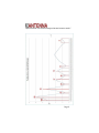
1
"Alpha Antenna uses antenna designs that are known to work!" Alpha Antenna Model ‐ Alpha 6‐160 The 6‐160 Meter HF J‐Pole USER GUIDE V2.1 October 12, 2011 Page 1 "Alpha Antenna uses antenna designs that are known to work!" Page 2 "Alpha Antenna uses antenna designs that are known to work!" Introduction Thank you for purchasing the Alpha 6‐160 from Alpha Antenna. At 75 feet in length the unique design characteristics of your 6‐160 Meter HF J‐Pole antenna enables it to achieve resonance on the major HF bands (6/10/15/20/40 Meters) and presents a SWR on all of the HF bands, including 80 & 160 Meters, that is low enough for 10:1 tuners to achieve a perfect match. Alpha Antenna uses antenna designs that are known to work! De‐ signed by Amateur Radio Operators at Alpha Antenna, in conjunction with a Certified Commercial Broadcast Engineer, the Alpha Antenna 6‐ 160 merges the best antenna designs into one antenna system. Technical Specifications Weight: 2.5 pounds Configuration: Vertical, Inverted L, Horizontal Frequency Coverage: 1.8 to 54 MHz Power Rating: 200 watts Length: 75 Feet Page 3 "Alpha Antenna uses antenna designs that are known to work!" Functional Description A combination of antenna designs, namely the J‐Pole and Zepp along with matching network technologies, are utilized to achieve a resonant antenna design on 6, 10, 15, 20, & 40 Meters and a fairly resonant pat‐ tern on the rest of the HF bands, including 80 & 160 Meters. From the J‐Pole formulas we derive the lengths of each wire pair, spacing of the wiring between their respective sheaths, and size & number of the strands of the wire used. From the Zepp is the matching feeder ele‐ ment formula, and although significant, is by no means the only factor in matching the antenna. A 4:1 UNUN utilizes compliments that Match‐ ing Network of the antenna. The 4:1 UNUN allows for the antenna to be fed with 50 ohm coax at the antenna. This makes for an important design characteristic when feeding a tuner, as it keeps the RF voltages low at the feed point. Then, depending upon what band you are you, a tuner can be used to perform the final matching for resonance. Installation Safety WARNING: INSTALLATION OF THIS PRODUCT NEAR POWER LINES IS DANGEROUS! FOR YOUR SAFETY, FOLLOW THE ENCLOSED INSTALLATION DIRECTIONS. THOUGH THIS ANTENNA IS CONSTRUCTED OF INSULATED WIRE, PROPER CARE MUST BE TAKEN DURING INSTALLATION. INSTALLER ASSUMES ALL LIABILITY FOR PROPERTY AND LIFE SAFETY. YOU, YOUR ANTENNA, AND SAFETY Page 4 "Alpha Antenna uses antenna designs that are known to work!" Each year, hundreds of people are killed, mutilated, or receive severe and permanent injuries when attempting to install an antenna. In many of these cases, the victim was aware of the danger of electrocu‐ tion, but did not take adequate steps to avoid the hazard. For your safety, and to help you achieve a good installation, please READ and FOLLOW the safety precautions below. THEY MAY SAVE YOUR LIFE! 1. If you are installing an antenna for the first time, please, for your own safety as well as others, seek PROFESSIONAL ASSISTANCE. 2. Select your installation site with safety, as well as performance, in mind. (Detailed information in Site Selection appears in a separate sec‐ tion of this booklet.) REMEMBER: ELECTRIC POWER LINES AND PHONE LINES LOOK ALIKE. FOR YOUR SAFETY, ASSUME THAT ANY OVERHEAD LINES CAN KILL YOU. 3. Call your electric power company. Tell them your plans and ask them to come take a look at your proposed installation. This is a small inconvenience, considering YOUR LIFE IS AT STAKE. 4. Plan your installation procedure carefully and completely before you begin. Successful raising of a mast or tower is largely a matter of coor‐ dination. Each person should be assigned a specific task, and should know what to do and when to do it. One person should be designated as the leader/coordinator of the operation to call out instructions and watch for signs of trouble. Page 5 "Alpha Antenna uses antenna designs that are known to work!" 5. When installing your antenna, REMEMBER: DO NOT USE A METAL LADDER. DO NOT WORK ON A WET OR WINDY DAY. DO DRESS PROPERLY: shoes with rubber soles and heels, rubber gloves, long sleeved shirt or jacket. 6. If the assembly starts to drop, get away from it and let it fall. Re‐ member, the antenna, mast, cable and metal guy wires are all excel‐ lent conductors of electrical current. Even the slightest touch of any of these parts to a power line completes an electrical path through the antenna and the installer – THAT’S YOU! 7. If ANY PART of the antenna system should come in contact with a power line, DON’T TOUCH IT OR TRY TO REMOVE IT YOURSELF. CALL YOUR LOCAL POWER COMPANY. They will re‐ move it safely. If an accident should occur with the power lines, call for qualified emergency help IMMEDIATELY. Antenna Installation There are several basic methods to installing the antenna. The most common methods are Horizontal and Inverted L, where the feed point or center of the antenna is tied to a pole or high object in order to get the radiator as high in the air as possible. The best rule of thumb is to get it as high off the ground as possible for your situation. Other than that, even if you install it in a different shape to fit your apartment, condo or other installation, the antenna is pretty forgiving. Page 6 "Alpha Antenna uses antenna designs that are known to work!" Since the antenna can be used in either permanent or temporary in‐ stallations, finding a good place for the antenna is just a matter of ex‐ amining your location. Try to keep the entire antenna away from metal objects, including metal siding of houses or metal poles, water pipes, rain gutters, etc. 70% of the power radiated from the antenna is in the first 1/3 of the antenna where the coax attaches. It is important to affix the start point of then antenna to objects like trees, roofs, chimneys or string it up with a nonconductive cable (nylon rope) to get the start point as high off the ground as possible. The antenna will perform best when both ends are high off the ground. Connection to HF Radio The Alpha 6‐160 antenna is designed to directly connect to your tuner or radio’s tuner with standard 50 ohm coax. To connect the antenna to your tuner, simply screw the PL‐259 end of your coax into the Alpha 6‐ 160 antenna and the other end into to your tuner or radio. This an‐ tenna is designed to be fed with unbalanced or balanced feed line. Page 7 "Alpha Antenna uses antenna designs that are known to work!" Optimum SWR Performance The SWR for the Alpha 6‐160 HF‐J‐Pole has been tested at heights from just 6 feet through 30 feet and comes pre‐tuned. During tests, opti‐ mum results achieved are represented in the following SWR Analysis. These results will vary for your particular installation based upon ob‐ jects in your surrounding environment. If you do not have a tuner or if necessary, you can incrementally tune the Alpha 6‐160 using the tun‐ ing stub.* This involves selecting the center frequency that you will operate on and trimming a short amount (1‐3 inches at a time) of the shorter wire. This should be done using an antenna analyzer for opti‐ mum results. Although the SWR will not change much as 1‐3 inches of wire are trimmed, eventually you will see the SWR start to increase, at which time you need to stop trimming. It is necessary to take precise readings on each band and monitor for when the first band starts to increase, which is an indication that it’s about time to stop trimming. * Tuning through trimming the tuning stub invalidates any implied or stated warrantees. Note the Trouble‐ shooting section before you attempt to trim the tuning stub. Page 8 "Alpha Antenna uses antenna designs that are known to work!" Page 9 "Alpha Antenna uses antenna designs that are known to work!" Troubleshooting If your antenna isn’t tuning up properly, simply try moving it. Chances are, you have it in a position that is causing an odd SWR and the tuner doesn’t like it. If your antenna is giving unwanted TVI or RFI to other equipment in the house, you may also need to reposition the antenna. This is mostly the case for installations where the antenna is running parallel to ground. This creates a large reflection to ground, which tends to create interference in the shack and the house. To eliminate this issue, try installing as much of the antenna in a vertical configuration as you pos‐ sibly can, still following the other rules for standards antenna installa‐ tion presented here in this manual and in the ARRL Handbook. If you are running an inverted “L” and you aren’t getting too much DX, try repositioning to a sloper or vertical (sloped or straight up). The in‐ verted “L” positioning tends to give a NVIS, straight up, directive and you will only tend to get local stations with this positioning. Have Other Questions? If you have questions about your antenna, please feel free to contact us. Page 10 "Alpha Antenna uses antenna designs that are known to work!" Support Email: [email protected] Phone: 1‐888‐482‐3249 WEB: www.alphaantenna.com Page 11 "Alpha Antenna uses antenna designs that are known to work!" NOTES Page 12