1
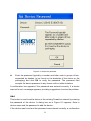
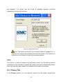
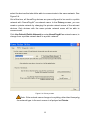
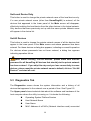
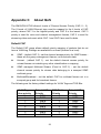
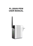
USER GUIDE EZ Connect Powerline™ 200Mbps HomePlug AV Adapter SMCHPAV-ETH2 Copyright Information furnished by SMC Networks, Inc. (SMC) is believed to be accurate and reliable. However, no responsibility is assumed by SMC for its use, nor for any infringements of patents or other rights of third parties which may result from its use. No license is granted by implication or otherwise under any patent or patent rights of SMC. SMC reserves the right to change specifications at any time without notice. Copyright © 2010 by SMC Networks, Inc. 20 Mason Irvine, CA 92618 Europe: SMC Networks Spain S.L. C/Fructuós Gelabert 6-8, 2º, 2ª Edificio Conata II 08970 Sant Joan Despí Barcelona, Spain All rights reserved. Printed in China Trademarks: SMC is a registered trademark; and EZ Connect Powerline is a trademark of SMC Networks, Inc. Other product and company names are trademarks or registered trademarks of their respective holders. Warranty and Product Registration To register SMC products and to review the detailed warranty statement, please check www.smc.com for the warranty terms in your country/region. SMC Networks, Inc. 20 Mason Irvine, CA 92618 Compliances EC Declaration of Conformity SMC contact for these products in Europe is: SMC Networks Spain, S.L. Edificio Conata II, Fructuós Gelabert 6-8 2º 2ª 08970 Sant Joan Despí, Barcolona,Spain This product indicates compliance with the Essential Requirements of the EMC Directive (2004/108/EC) and the LVD Directive (2006/95/EC) of the European Union. This equipment meets the following conformance standards. EN 60950-1: 2006 EN 61000-3-2: 2006 EN 61000-3-3 : 1995+A1:2001+A2:2005 EN 55024: 1998+A1:2001+A2:2003 EN 55022: 1998+A1:2000+A2:2003 The official CE certificate of conformity can be downloaded by selecting the relevant model/ part number from www.smc.com -> support -> download" Contents 1 Introduction ................................................................................................ 1 1.1 Minimum System Requirements ...................................................... 1 1.2 Package List..................................................................................... 1 2 Safety Cautions ......................................................................................... 2 3 Hardware Overview ................................................................................... 3 3.1 Ethernet Interface............................................................................. 3 3.2 Buttons ............................................................................................. 3 3.3 LEDs................................................................................................. 3 4 Installing the Configuration Utility for Windows.......................................... 5 5 Working with the Configuration Utility for Windows ................................... 8 6 5.1 Main Tab .......................................................................................... 8 5.2 Privacy Tab .................................................................................... 12 5.3 Diagnostics Tab.............................................................................. 14 5.4 About Tab....................................................................................... 16 SYNC button Usage ................................................................................ 17 6.1 Creating a private network ............................................................. 17 6.2 Joining a Network........................................................................... 18 6.3 Leaving a Network.......................................................................... 19 Appendix A Specifications ................................................................... 21 Appendix B Acronyms and Abbreviations ........................................... 22 Appendix C About QoS........................................................................ 23 1 Introduction Thank you for purchasing an SMC product. The SMCHPAV-ETH2 is a fast 200Mbps* Powerline HomePlug AV Ethernet Adapter which allows you to connect computers, or Ethernet-enabled devices in your home or office and to share an Internet connections through the in-house electrical wiring . *200Mbps—is the physical data rate. Actual data throughput may be lower. 1.1 Minimum System Requirements For Configuration Utility, computer with - 200MHz above CPU with 128MB RAM - 20MB free disk space - 10/100Mbps Ethernet Adapter with RJ-45 connector - Windows 7, Vista, XP (with SP2) or 2000 (with SP4) For Hardware Installation - At least 2 HomePlug AV devices - Available power outlet - Available Ethernet port with RJ-45 connector on each computer or networking device 1.2 Package List z 1 SMCHPAV-ETH2 HomePlug AV Ethernet Adapter z 1 CD-ROM with software utility and user manual z 1 RJ-45 Ethernet cable z 1 Quick Installation Guide z 1 Warranty Information Card 1 2 Safety Cautions This device is used for connection to the AC electrical wiring. In order to use the device correctly and safely please read the instructions before using the device. For installation instructions, please refer to the installation section of this user guide. z z Follow all the warnings and instructions marked on the product. Before cleaning the device, unplug it from the wall outlet. Use a dry cloth for cleaning. Do not use liquid or aerosol cleaners. z Do not place the device near water. z Do not place the device near or over a radiator or heat register. z Do not use an extension cord between the device and the power outlet. z Only professional technicians should service the device. Opening or removing covers may result in exposure to dangerous voltage points or other risks. z Unplug the device from the power outlet and refer to professional service personnel for the following conditions: – If liquid has been spilled into the product. – If the device has been exposed to rain or water. – If the device does not operate normally when following the operation instructions. – If the device shows a significant change in performance. 2 3 Hardware Overview 3.1 Ethernet Interface Use one end of the network cable included in the box to connect to the Ethernet port (RJ-45) of the SMCHPAV-ETH2. Use the other end of the cable to connect to the Ethernet port (RJ-45) of a computer or any other Ethernet-enabled networking device. 3.2 Buttons Figure 3-1 Side panel Reset: Restore the factory default settings. Sync: Activate network security. Refer to chapter 6 for more information. 3.3 LEDs As shown in Figure 3-2, there are 3 LEDs on the front panel to indicate the status of the adapter: 3 Power LED - Green LED: Power on. - OFF: Power off. Ethernet LED - Green LED: The Ethernet connection is ready. - Blinking: The Ethernet connection is transmitting or receiving data. - OFF: No Ethernet network activity. Data LED - Blinking: The Powerline connection is transmitting or receiving data. - Red LED: Low link speed (Data rate is slower than 30Mbps) - Yellow LED: Normal link speed (Data rate is between 30-50Mbps) - Green LED: Excellent link speed (Data rate is faster than 50Mbps) - OFF: No Powerline network activity Figure 3-2 Top view 4 4 Installing the Configuration Utility for Windows z Before installing the configuration utility for Windows 7/Vista/XP/2000, please make sure that no other Powerline utility is installed on the computer. If another Powerline utility is already installed, please uninstall it and reboot the computer. z Insert the CD-ROM with the utility into the CD-ROM drive of the computer. Select SMCHPAV-ETH2 Utility Installation and double-click Setup.exe. Follow the on-screen instructions to install the utility. No password or CD-Key is needed. The installation process is similar to the one shown in Figures 4-1 to 4-4: Figure 4-1 Setup wizard 5 Figure 4-2 Select installation folder 6 Figure 4-3 Confirm Installation Click Next to start the installation. 7 Figure 4-4 Installation complete Click Close to complete the installation. 5 Working with the Configuration Utility for Windows 5.1 Main Tab The Main screen provides a list of all HomePlug AV devices logically connected to the computer where the utility is running on. The top panel shows all devices that are found locally connected to the computer where the utility is running on. In most cases, only one device will be listed here.. Select it and click the Connect button. The utility automatically 8 scans the Powerline network periodically for other HomePlug AV. If no local HomePlug device has been found, the status bar displays NO HOMEPLUG ADAPTERS DETECTED. Figure 5-1: Main tab information The lower panel provides detailed information about all HomePlug AV devices found in the Powerline network. The total number of devices connected to the network is displayed in a line above the device names (1 Powerline Device detected in Figure 5-1). Network type (Public or Private) depends on the network name of the local device (please refer to the chapter 5.2 for more information). Autoscan/Scanning… shows whether the autoscan function is on and active. The following information is displayed for all devices that appear in the list: Device Name This column shows the default device name, which may be modified. To change the name of a device, select the device and click Rename or click the name and 9 edit it in the list. Password By default, this column is blank. You can select a device and click Enter Password to change it (see below). Quality This shows the signal quality in form of a progress bar. Rate (Mbps) This column indicates the current data rates in Mbps. MAC Address The last column shows the MAC address of the each device. Enter Password The password is necessary to activate security in the Powerline network and to control all HomePlug AV devices from one computer. To activate security you need to create a so-called “private network” by changing the private network name in all HomePlug AV devices. This will only be possible after entering the password for all these devices. The procedure for setting the password of the device (required when creating a private network) is as follows: z z Click the device name to select the device in the lower panel. Click Enter Password. A dialog box appears, showing the device name, MAC address and a field to enter the password. See Figure 5-2. 10 Figure 5-2: Set device password z Enter the password (typically a number and letter code in groups of four, separated by dashes, to be found on the backside of the device or the packaging) and click OK to verify the password. The password field accepts the device password in any format, with or without dashes. A confirmation box appears if the password was entered correctly. If a device was not found, a message appears, providing suggestions to solve the problem. Add This button is used to add a device to the existing Powerline network by entering the password of the device. A dialog box as in Figure 5-3 appears. Enter a device name and the password to add the device. If the device was found and the password was entered correctly, a confirmation 11 box appears. If a device was not found, a message appears, providing suggestions to solve the problem. Figure 5-3: Add remote device Note: The device must be in the Powerline network (plugged in), so that you can confirm the password and add the device to the network. If the device is not located, a warning message appears. Scan This button is used to perform an immediate search for HomePlug devices connected to the Powerline network. By default, the utility automatically scans every few seconds and updates the displayed information accordingly. 5.2 Privacy Tab In the Privacy screen, you can maintain security for the logical network and 12 select the devices that should be able to communicate in the same network. See Figure 5-4. Out-of-the-box, all HomePlug devices are pre-configured to be used in a public network with “HomePlugAV” as network name. In the Privacy screen, you can create a private network by changing the private network name of the relevant devices. Only devices with the same private network name will be able to communicate. Click Use Default (Public Network) or enter HomePlugAV as network name, to change from a private network back to a public network. Figure 5-4: Privacy screen Note: If the network name changes to anything other than Homeplug, the network type in the main screen is displayed as Private. 13 Set Local Device Only This button is used to change the private network name of the local device only. If a new private network name (other than HomePlugAV) is entered, all the devices that appeared in the lower panel of the Main screen will disappear, effectively isolating the local device from the other devices in the logical network. Only devices that were previously set up with the same private network name still appear in the device list. Set All Devices This button is used to change the private network names of all the devices that appear in the lower panel of the Main screen and whose password has been entered. For these devices a dialog box appears, indicating successful operation. For devices whose passwords has not been entered, a dialog box appears indicating operation failure. Note: Before clicking “Set All Devices” please make sure that the password for all HomePlug AV devices that should join the private network has been entered . If you skip this step and you lose connectivity to some devices, please reset the private network name to default, click on “Set All Devices” and start all over. 5.3 Diagnostics Tab The Diagnostics screen shows the system information and a history of all devices that appeared in the network over a period of time. See Figure 5-5. The Upper panel shows technical data about the software and hardware of the host computer where the utility is running on. It includes the following: Operating System Platform/Version Host Network Name User Name MAC Address of all NICs (Network interface card) connected 14 to the host Identify versions of all Driver DLLs and Libraries used (NDIS) and optionally HomePlug chipset manufacturer name MAC Firmware Version MAC addresses of all devices connected locally to the host Version of the Configuration Utility Vendor name Figure 5-5: Diagnostics screen The Lower panel displays the history of all devices that appeared on the computer over a certain period of time. All the devices and the parameters of the devices on the powerline network are listed. Devices that are active on the current logical network show a transfer rate in the rate column. Devices on other networks, or devices that no longer exist are shown with a “?” in the rate column. 15 The following remote device information is available from the diagnostics screen: Device Name MAC Address Password Last known data rate Last known network name Homeplug chipset manufacturer name Date when the device was last seen on the network MAC Firmware Version The displayed diagnostics information can be saved to a text file for later use, or be printed for reference for a technical support call. Click Delete to delete the devices which are no longer part of the network. A dialog box will pop up with a confirmation message if you want to delete a device whose password has been entered. 5.4 About Tab The About screen shows the software version and provides an HTML link to a website, such as www.smc.com. Clicking the web address, will open the website in your web browser. 16 Figure 5-6: About screen 6 SYNC button Usage This section describes how to add or remove devices from a Powerline network by using the SYNC button on the devices. This process allows to create a Powerline network without using the configuration utility for Windows and works independent from the operating system. 6.1 Creating a private network When two devices with different SYNC values are connected to the same Powerline private network, they need to be synchronized to be able to communicate: 1. Press the SYNC button on device A for less than 3 seconds. 2. Press the SYNC button on device B for less than 3 seconds. 17 The button on device B must be pressed within 1 minute. 3. Wait for the SYNC process to complete. The Power LED on both devices will blink evenly at 1-second intervals until the operation succeeded or failed. If the connection succeeded, it illuminates steadily. If an error occured, the Power LED on the ‘adder’ (Device B) blinks unevenly until the SYNC button on the ‘adder’ (Device B) is pressed again or the ‘joiner’ (Device A) is reset by pressing the SYNC button down for more than 10 seconds. Figure 6-1: Creating a Homeplug AV private network 6.2 Joining a Network In this scenario a Powerline private network exists and a new device, the ‘joiner’, should join the network. Any device on the existing Powerline network can become the ‘adder’. 1. Press the SYNC button on the ‘joiner’ (new device) for at least 3 seconds. 2. Press the SYNC button on any network device for less than 3 seconds, making it the ‘adder’ (existing device). Please press this 3. SYNC button within 1 minute. Wait for the connection to complete. The Power LED on both devices will blink evenly at 1-second intervals until the operation succeeded or failed. If the connection succeeded, it illuminates steadily. If an error occured, the Power LED on the ‘adder’ blinks unevenly until 18 the SYNC button on the ‘adder’ is pressed again or the ‘joiner’ is reset by pressing the RESET button down for more than 10 seconds. Figure 6-2: Joining a network 6.3 Leaving a Network In this scenario a Powerline network exists and one device, the ‘leaver’, should be removed from the network. The user either wants to remove the device completely or have it join another logical network. 1. Press the SYNC button on the ‘leaver’ for at least 10 seconds. The device resets and restarts with a random SYNC. 2. Wait for the reset to complete. The Power LED on the ‘leaver’ momentarily extinguishes during reset, blinks during restart, then illuminates steadily. No error occurs. The user can disconnect the device from the medium or join it to another logical network on the same medium when the reset process is completed. 19 Figure 6-3: leaving a network 20 Appendix A Specifications Protocol Compliant with HomePlug AV 1.0 Co-existing with existing HomePlug 1.0 System Support Powerline Data Rate Windows 98SE, Windows 2000, Windows ME, Windows XP 32/64 bit and Windows Vista 32/ 64bit 200 Mbps Modulation Band 2MHz~30MHz Modulation Schemes Support QAM 1024/256/64/16/8, QPSK, BPSK and ROBO 128 AES Encryption LED Indicators Power LED Ethernet LED Data LED Buttons Reset: Restore the default factory settings SYNC: Set up network password automatically Consumption 3.5 W Max. Operating Temperature 0ºC~45ºC Storage Temperature -20ºC~70ºC Operating Humidity 10%~90%, non-condensing Storage Humidity 5%~90%, non-condensing Power Supply 100 V~240 V AC, 50Hz~60Hz Certifications CE, UL, FCC Part 15 Class B Green Standard RoHS 21 Appendix B AVLN Acronyms and Abbreviations AV In-home Logical Network, the AVLAN is the set of STAs that possess the same network Membership key, every AVLN is managed by a single CCo CCo Central Coordinator, the CCo is a superset of a STA which includes terminal equipment identifiers and global link identifiers CSMA/CA Carrier Sense Multiple Access / Collision Avoidance DAK Device Access Key DM Device Manager IGMP Internet Group Management Protocol NEK Network Encryption Key NID Network ID (Identification) SYNC Synchronize Device PLC PowerLine Communication PIB Parameter Information Block STA Station, a STA in the network with a connection to the Powerline network and being able to source or sink traffic TDMA Time Division Multiple Access TEI Terminal Equipment Identifier TOS Type of Service VLAN Virtual Local Area Network 22 Appendix C About QoS The SMCHPAV-ETH2 allows 4 levels of Channel Access Priority (CAP, 0 – 3). The 8 levels of VLAN Ethernet tags must be mapped to the 4 levels of CAP priority, where CAP 3 is the highest priority and CAP 0 is the lowest. CAP 3 priority is used for voice and network management frames, CAP 2 is used for streaming video and music while CAP 1 and CAP 0 are used for data. Default CAP The Default CAP group allows default priority mapping of packets that do not have a VLAN tag. Settings are available for unicast (directed to a host). z IGMP - (default CAP 3) - set the channel access priority for IGMP frames these are the group management frames, not the stream data z Unicast - (default CAP 1) - set the default channel access priority for unicast frames not matching any other classification or mapping. z IGMP managed Multicast Stream (Fixed to CAP 2) - set the default channel access priority for stream data belonging to a snooped IGMP multicast group. z Multicast/Broadcast - set the default CAP for multicast frames not in a snooped group and for broadcast frames. The following are the factory default settings for VLAN Tags and TOS Bits: VLAN Tag User priority 0 1 2 3 4 5 6 7 Default CAP Priority CAP1 CAP0 CAP0 CAP1 CAP2 CAP2 CAP3 CAP3 TOS Bit User Priority 0 1 2 3 4 5 6 7 23 Default CAP Priority CAP1 CAP0 CAP0 CAP1 CAP2 CAP2 CAP3 CAP3 SMCHPAV-ETH2