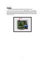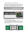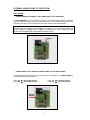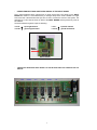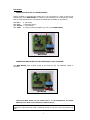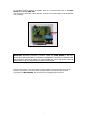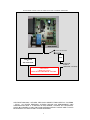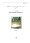
1
ABBRES
Audio Remote Control System
USER MANUAL
ATTENTION ! :
- Please read carefully each part of this manual.
- Designers of this kit decline any responsibility of improper use of this system
- When the board has to be connected to the 220V or 110V high voltage, boards need to be
correctly insulated to avoid risk of electric shock. Insulation missing of the boards could cause
dangerous consequences to the people.
- System must not to be exposure to wet or rain or any other kind of liquids. Moreover need to be
correctly ventilated during his working.
- Wired connections between the two boards and external power supply have to be correctly
done using insulated wires.
- Boards and components on the boards need to be not reached from people during they are
working.
- If points above are not observed system could be damaged or it could cause damages to the
people.
Audio Remote Control System ABBRES is made of two electronic boards, an infrared remote
control unit, a display LCD back-lighted and a IR sensor diode to receive signals from remote
unit. One of the two boards, we call INPUT BOARD, handles commutation audio input signals on
selecting audio input source (CD, Tape, Aux, …) The other board, we call MAIN BOARD,
handles INPUT BOARD , motorized potentiometer, infrared IR diode, LCD display unit, a relay to
switch on/off external preamplifier or power amplifier. System is equipped with screw terminal
blocks to ease the connections. Each screw terminal block or connector is marked by a label on
the top of the PCB for each board. This manual refers to these labels to explain how you do all
the connection.
INTERNAL SYSTEM CONNECTIONS :
- CONNECTING INPUT BOARD AND MAIN BOARD
To connect INPUT BOARD to the MAIN BOARD you need to use the 3-wired terminals block on
both boards marked with char A,B,C. Terminal A of a board has to be connected to the relative
terminal A of the other board. The same for terminal B and C. Connection scheme is illustrated in
the table below.
Terminal block
INPUT BOARD
A
B
C
Terminal block
MAIN BOARD
Æ
Æ
Æ
A
B
C
INPUT BOARD
1
MAIN BOARD
MAIN BOARD
-
CONNECTING MAIN BOARD WITH MOTORIZED POTENTIOMETER (ALPS)
Connector for motorized potentiometer is placed on the MAIN BOARD and it’s marked MOTOR.
As on the market you can find several motorized potentiometers with different polarities it has not
been marked any polarity that can be found swapping the two wired connections. It is possible
easily verify if the polarity is correct, rising volume by the remote control unit (pushing VOL+ key)
and checking that potentiometer increments his position clockwise. If it’s not, you need swap the
two wired connections.
MOTOR
MAIN BOARD
2
-
CONNECTING MAIN BOARD WITH IR RECEIVER SENSOR DIODE
Receiver IR diode is an integrated circuit with 3 pins and his part number is TSOP1736 produced
by VISHAY Telefunken (also TSOP1836 is full compatible). Together with this manual it’s
provided the pin-out sheet of the TSOP1736. This TSOP1736 has to be connected in a 3 pins
connector placed at the center of the MAIN BOARD using 3 insulated wires, if possible twisted
it’s better. We suggest you use 3 wires with 3 different colors to avoid any confusion.
ATTENTION! IT’S MANDATORY TO CORRECTLY CONNECT THE PINS OF THE IR DIODE
TO THE 3-PINS CONNECTOR ON THE MAIN BOARD OTHERWISE IR DIODE COULD
REMAIN PERMANENTLY DAMAGED.
The connector is placed round to the center of the main and it’s marked with the labels VCC GND
and IR at the ends of the 3 pins. Following it’s illustrated the correspondence between IR
TSOP1736 pins (called GND, Vs , OUT in his datasheet), and the pins of the MAIN BOARD
connectors.
IR DIODE pin
GND
Vs
OUT
Æ
Æ
Æ
3-pins on MAIN BOARD
GND
VCC
IR
IR DIODE
MAIN BOARD
-
CONNECTING MAIN BOARD WITH LCD DISPLAY
The LCD display has a 1x16 row connector and it has to be connected to the relative connector
(1x16 row pins) on the MAIN BOARD by a dedicated cable.
Pin number 1 on both row connectors (MAIN BOARD and LCD display) have to be linked
together. Connection can be performed by a flat cable (typically used for IDE hard-disk provided
in the kit). The flat cable is a 34pins (2x17 row pins) so you will use only 1x16 row pins and need
to align the same ends of the cable to the LCD display and board connector. Example of
connection in the following picture:
This row is not used
LCD
FLAT CABLE
34 pins (17x2 row pins)
This row is not used
MAIN BOARD
Pin 1
Pin 1
16 pins used
16 pins used
3
EXTERNAL CONNECTIONS TO THE SYSTEM:
INPUT BOARD
-
CONNECTING INPUT BOARD TO THE POWER SUPPLY (NOT PROVIDED)
The INPUT BOARD has to be supplied in a range [7V..9V]. Non stabilized voltage is permitted.
Positive voltage of the supply has to be connected to the side of the terminal block labeled +VCC
while the ground has to be connected to the side of the terminal block with label GND.
ATTENTION! PROVIDING A VOLTAGE >9V THE REGULATOR AND THE RELE’ CAN BE
DAMAGED BY OVERHEATING. PROVIDING A VOLTAGE <7V IT’S NOT GUARANTEED THE
RELAY STABILITY. POWER SUPPLY NEEDS TO PROVIDE AT LEAST 500mA AS TWO
RELIES ARE WORKING AND POTENTIOMETER NEED 150 mA.
SUPPLY
INPUT BOARD
-
CONNECTING OUTPUT ANALOGUE AUDIO SIGNAL OF THE INPUT BOARD
Output audio signal (left and right), that goes to the input of the amplifier, is on INPUT BOARD by
a 4 wired terminal block as following:
Label RO Æ output right channel
Label MR Æ ground right channel
Label LO Æ output left channel
Label ML Æ ground left channel
OUTPUT
SIGNAL
INPUT BOARD
4
-
CONNECTING INPUT ANALOGUE AUDIO SIGNAL OF THE INPUT BOARD
The 6 inputs analogue stereo (coming from an audio source like a CD player) on the INPUT
BOARD are visible in 6 zone marked off by a rectangle shape. Each zone is related to a single
source and has 4 terminal holes that you have to use to connect the source to the system. The
terminals are in this case the holes on PCB of the INPUT BOARD and they admit only wires to
be soldered.
Terminals related to a generic input are following:
Label R Æ
Label M Æ
Label L Æ
Label M Æ
input right channel
ground right channel
input left channel
ground left channel
INPUT
SIGNAL
INPUT BOARD
-
CONNECTING ANALOGUE AUDIO SIGNAL TO THE RELATIVE INPUT AS SHOWN IN THE LCD
DISPLAY
iPOD
PHONO
AUX
DVD
TUNER
5
CD
MAIN BOARD
-
CONNECTING BUTTONS TO THE MAIN BOARD
Buttons (optional) to command the system have to be connected by 4 pairs of small 2-wire
terminal block on the MAIN BOARD. As buttons do not have polarity, it’s not marked any polarity
label on these terminal blocks, while instead it’s marked the functionality for each button:
label VOL+
label VOLlabel INPUTS
label PWR
Æ rise volume
Æ decrease volume
Æ input selection
Æ power-on/off of the amplifier (by a rele’ on the MAIN BOARD)
TO BUTTONS
MAIN BOARD
-
CONNECTING MAIN BOARD TO THE POWER SUPPLY (NOT PROVIDED)
The MAIN BOARD need a power supply in the range [7V..9V]. Not stabilized voltage is
permitted.
MAIN BOARD
-
SUPPLY
CONNECTING MAIN BOARD TO THE POWER SUPPLY OF THE PREAMPLIFER OR POWER
AMPLIFIER THAT NEED TO BE CONTROLLED (SWITCH ON/OFF)
ATTENTION! WORKING WITH HIGH VOLTAGE 220V or 110V ALL CONNECTIONS NEED TO BE
CORRECTLY INSULATED AND DONE OTHERWISE THERE IS THE RISK OF ELECTROSHOCK OR
FIRE
6
To command switching on/off of an amplifier there is a 2-wired terminal block on the MAIN
BOARD that is labeled PWR AMP.
This connector is simply like a switch ON/OFF, in series to the power supply line of the amplifier
to be controlled
PWR AMP
MAIN BOARD
IMPORTANT! MAXIMUM HANDLING CURRENT FROM THE MAIN BOARD IS 4A THAT
NEVER MUST BE OVERCOME. IT’S STRONGLY SUGGESTED TO INSERT A PROPER FUSE
AND A MANUAL SWITCH IN SERIES TO THIS CONNECTOR. THIS FUSE SHOULD BE THE
ORIGIN SAFE FUSE OF THE AMPLIFIER TO BE CONTROLLED.
Fuse and main switch, in the picture below, must be present in the power supply circuit of the
amplifier or the system you want to control. Systems absorb more than 4A never must be
connected to the MAIN BOARD. See picture below for suggested safe connection.
7
SUGGESTED CONNECTION TO SWITCH ON/OFF A POWER AMPLIFIER
MAIN BOARD
MANUAL SWITCH
FUSE
AMPLIFIER
or
PREAMPLIFIER
VOLTAGE
SUPPLY
(220V/110V - 4A MAX)
ATTENTION !
-- HIGH VOLTAGE -RISK OF ELECTROSHOCK AND FIRE
COPYRIGHT 2008-2009 – AUTHORS PIER PAOLO ABBATE E FABIO RESTIVO – PALERMO
– ITALIA. ALL RIGHTS RESERVED. AUTHORS DECLINE ANY RESPONSIBILITY AND
COMPENSATION WHAT IT IS WRITTEN IN THIS MANUAL. CONTENT OF THIS MANUAL
COULD BE CHANGED AT ANY TIME FROM AUTHORS WITHOUT NOTICE AND IT COULD
BE DIFFERENT TO THE SYSTEM IT IS NOW REFERRING.
8