1
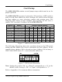
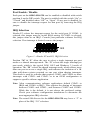
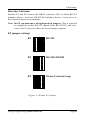
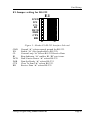
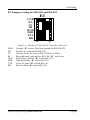
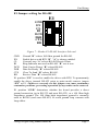
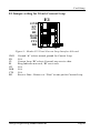
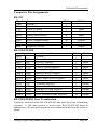
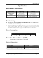
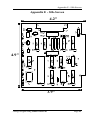
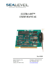
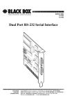
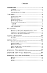
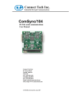
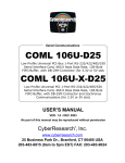
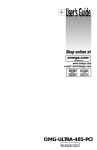
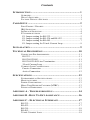
Contents
INTRODUCTION ..................................................................... 1
OVERVIEW .................................................................................. 1
WHAT’S INCLUDED ..................................................................... 1
FACTORY DEFAULT SETTINGS ..................................................... 1
CARD SETUP ......................................................................... 2
PORT ENABLE / DISABLE ............................................................. 3
IRQ SELECTION .......................................................................... 3
INTERFACE SELECTION ................................................................ 4
E2 JUMPER SETTINGS .................................................................. 4
E1 Jumper setting for RS-232.................................................. 5
E1 Jumper setting for RS-530 and RS-422 .............................. 6
E1 Jumper setting for RS-485.................................................. 7
E1 Jumper setting for 20 mA Current Loop............................. 8
INSTALLATION ...................................................................... 9
TECHNICAL DESCRIPTION .................................................. 10
CONNECTOR PIN ASSIGNMENTS ................................................. 11
RS-232.................................................................................. 11
RS-530/422/485 .................................................................... 11
RS-530/422/485 Line Termination ........................................ 11
20 mA Current Loop ............................................................. 12
CURRENT LOOP CONNECTIONS .................................................. 12
Passive Connection ............................................................... 12
Active Connection................................................................. 12
SPECIFICATIONS ................................................................. 13
ENVIRONMENTAL SPECIFICATIONS ............................................. 13
MANUFACTURING ..................................................................... 13
POWER CONSUMPTION .............................................................. 13
MEAN TIME BETWEEN FAILURES (MTBF).................................. 13
PHYSICAL DIMENSIONS ............................................................. 13
APPENDIX A - TROUBLESHOOTING .................................... 14
APPENDIX B - HOW TO GET ASSISTANCE .......................... 16
APPENDIX C - ELECTRICAL INTERFACE ............................ 17
RS-232..................................................................................... 17
RS-422..................................................................................... 17
RS-530..................................................................................... 18
RS-485..................................................................................... 18
20 MA CURRENT LOOP ............................................................. 19
APPENDIX D - ASYNCHRONOUS COMMUNICATIONS .......... 20
APPENDIX E - SILK-SCREEN............................................... 21
APPENDIX F - SCHEMATIC ................................................. 22
APPENDIX G - COMPLIANCE NOTICES ............................... 23
COMPLIANCE NOTICES ......ERROR! BOOKMARK NOT DEFINED.
FEDERAL COMMUNICATIONS COMMISSION STATEMENT .............. 23
EMC DIRECTIVE STATEMENT.................................................... 23
WARRANTY ......................................................................... 24
Figures
Figure 1 - Address Selection Table........................................................2
Figure 2 - DIP-Switch Illustration .........................................................2
Figure 3 - Header E2 and E3, IRQ Selection........................................3
Figure 4 - Header E2 options.................................................................4
Figure 5 - Header E1 RS-232 Interface Selected ..................................5
Figure 6 - Header E1 RS-530/422 Interface Selected ...........................6
Figure 7 - Header E1 RS-485 Interface Selected ..................................7
Figure 8 - Header E1 20 mA Current Loop Interface Selected............8
Figure 9 - Asynchronous Communications Bit Diagram .................... 20
© 1996j Omega Engineering, Incorporated. All rights reserved.
Introduction
Introduction
Overview
The OMG-SIO-530 provides the PC with one asynchronous serial port
which can interface to RS-232, RS-422, RS-485, and 20 mA Current Loop
devices.
What’s Included
The OMG-SIO-530 is shipped with the following items. If any of these
items are missing or damaged, contact the supplier.
•
•
•
OMG-SIO-530 Serial I/O Adapter
3.5” Serial Utility Diskette
User Manual
Factory Default Settings
The OMG-SIO-530 factory default settings are as follows:
Base Address
3F8
IRQ
4
Electrical Specification
RS-232
To install the OMG-SIO-530 using factory default settings, refer to
Installation on page 9.
For your reference, record installed OMG-SIO-530 settings below:
Base Address
IRQ
Omega Engineering OMG-SIO-530
Electrical Specification
Page 1
Card Setup
Card Setup
The OMG-SIO-530 contains several jumper straps which must be set for
proper operation.
The OMG-SIO-530 occupies 8 consecutive I/O locations. A DIP-switch is
used to set the base address for these locations. Be careful when selecting
the base address as some selections conflict with existing ports. The
following table shows several examples that typically do not cause a
conflict. SW1 sets the I/O address for the OMG-SIO-530.
Address
Hex
280-287
2A0-2A7
2E8-2EF
2F8-2FF
3E8-3EF
300-307
328-32F
3F8-3FF
Binary
A9
A0
1010000XXX
1010100XXX
1011101XXX
1011111XXX
1111101XXX
1100000XXX
1100101XXX
1111111XXX
1
Off
Off
Off
Off
Off
Off
Off
Off
Switch Position Setting
2
3
4
5
6
On Off On On On
On Off On Off On
On Off Off Off On
On Off Off Off Off
Off Off Off Off On
Off On On On On
Off On On Off On
Off Off Off Off Off
7
On
On
Off
Off
Off
On
Off
Off
Figure 1 - Address Selection Table
The following illustration shows the correlation between the DIP-switch
setting and the address bits used to determine the base address. In the
example below, address 300 is selected as a base. Address 300 in binary is
XX11 0000 0XXX where X = a non-selectable address bit.
A9
A3 EN
ON
1
2
3
4
5
6
7
8
Figure 2 - DIP-Switch Illustration
Note: Setting the switch “On” or “Closed” corresponds to a “0” in the
address, while leaving it “Off” or “Open” corresponds to a “1”.
Refer to Appendix A for common address contentions.
Omega Engineering OMG-SIO-530
Page 2
Card Setup
Port Enable / Disable
Each port on the OMG-SIO-530 can be enabled or disabled with switch
position 8 on the DIP-switch. The port is enabled with the switch “On” or
“Closed” and disabled when “Off” or “Open”. If any port is disabled, be
sure to disable the interrupt request for that port by removing the IRQ
jumper.
IRQ Selection
Header E3 selects the interrupt request for the serial port. If COM1: is
selected, this jumper must be on the IRQ4 setting. If COM2: is selected,
this jumper must be on IRQ3. Consult your particular software for IRQ
selection. If no interrupt is desired, remove the jumper.
E3
MN75432
Figure 3 - Header E2 and E3, IRQ Selection
Position “M” & “N” allow the user to select a single interrupt per port
mode or a shared interrupt mode. The “N” selects the single interrupt per
port mode, which is the typical DOS, OS/2 and Windows 3.1 mode of
operation. The “M” selects the shared interrupt mode, which allows more
than one port to access a single IRQ, and indicates the inclusion of a 1K
ohm pull-down resistor required on one port when sharing interrupts.
This mode is used by software that requires COM3: and COM4: to share
interrupts with COM1: and COM2: or in an OEM configuration to
support a specific software application.
Note: Most communications software applications default COM3: to
IRQ4 and COM4: to IRQ3. This requires the sharing of interrupts
between COM1: and COM3:, and between COM2: and COM4:.
While this is the default, it is not always the preferred setting.
Check your software configuration instructions to determine the
most appropriate IRQ selection.
Note: The actual Silk-Screen for the OMG-SIO-530 may have a “2” in
place of the IRQ “2/9” selection.
Omega Engineering OMG-SIO-530
Page 3
Card Setup
Interface Selection
Headers E1 and E2 connect the DB-25 connector (P1) to either RS-232
interface drivers / receivers, RS-422/485 interface drivers / receivers or to
the Current Loop receiver interface.
Note: On E2 you must move all eight push-on jumpers. This is required
to completely isolate RS-232 signals from RS-422/485 and viceversa. On E1, however, there are several jumper options.
E2 jumper settings
E2
RS-232
E2
RS-530/422/485
E2
20 mA Current Loop
Figure 4 - Header E2 options
Omega Engineering OMG-SIO-530
Page 4
Card Setup
E1 Jumper setting for RS-232
E1
GND
EN
CL
RI
DCD
DSR
CTS
RD
B
A
Figure 5 - Header E1 RS-232 Interface Selected
GND
EN
CL
RI
DCD
DSR
CTS
RD
Ground “A” selects normal ground for RS-232.
Enable “A” (Not Applicable to RS-232).
Current Loop “A” selects RS-232 Receive Data.
Ring Indicator “A” enables RI, “B” sets it true.
Data Carrier Detect “A” selects RS-232.
Data Set Ready “A” selects RS-232.
Clear To Send “A” selects RS-232.
Receive Data “A” selects RS-232.
Omega Engineering OMG-SIO-530
Page 5
Card Setup
E1 Jumper setting for RS-530 and RS-422
E1
GND
EN
CL
RI
DCD
DSR
CTS
RD
B
A
Figure 6 - Header E1 RS-530/422 Interface Selected
GND
EN
CL
RI
DCD
DSR
CTS
RD
Ground “B” selects 100 Ohm ground for RS-530/422.
Enable “A” position for RS-530.
Current Loop “A” selects RS-530 Receive Data.
Ring Indicator (not used on RS-530) “B” sets it true.
Data Carrier Detect “B” selects RS-530.
Data Set Ready “B” selects RS-530.
Clear To Send “B” selects RS-530.
Receive Data “B” selects RS-530.
Omega Engineering OMG-SIO-530
Page 6
Card Setup
E1 Jumper setting for RS-485
E1
GND
EN
CL
RI
DCD
DSR
CTS
RD
B
A
Figure 7 - Header E1 RS-485 Interface Selected
GND
EN
CL
RI
DCD
DSR
CTS
RD
Ground “B” selects 100 Ohm ground for RS-485.
Enable driver with RTS “B” .”A” is always enabled.
Current Loop “A” selects RS-485 Receive Data.
Ring Indicator not used on RS-485 “B” sets it true.
Data Carrier Detect “B” selects RS-485.
Data Set Ready “B” selects RS-485.
Clear To Send “B” selects RS-485.
Receive Data “B” selects RS-485.
E1 position “EN” is used to enable the driver with RTS. To permanently
enable the driver (normal RS-422 point to point mode) remove jumper
“EN” at E1. Failure to correctly set this jumper can cause transmitter
contention problems, preventing operation by any nodes on the network.
E1 position “GND” determines whether the board provides a direct
ground connection (as in RS-232 and most RS-422), or a 100 Ohm high
impedance ground. The 100 Ohm high impedance ground is normally
used in RS-485 (and some RS-422) to avoid ground loop currents with
long cables.
Omega Engineering OMG-SIO-530
Page 7
Card Setup
E1 Jumper setting for 20 mA Current Loop
E1
GND
EN
CL
RI
DCD
DSR
CTS
RD
B
A
Figure 8 - Header E1 20 mA Current Loop Interface Selected
GND
EN
CL
RI
CD
DSR
CTS
RD
Ground “A” selects normal ground for Current Loop.
N/A
Current Loop “B” selects Current Loop receive data.
Ring Indicator not used, “B” sets it true.
N/A
N/A
N/A
Receive Data - Remove or “Float” on one pin for Current Loop.
Omega Engineering OMG-SIO-530
Page 8
Installation
Installation
The OMG-SIO-530 can be installed in any of the PC expansion slots, but
to access the “AT” or (E)ISA IRQ’s (10, 11, 12, 15) it must be installed in
one of the 16 bit slots. The OMG-SIO-530 contains several jumper straps
for each port which must be set for proper operation prior to installing the
adapter into the computer.
1.
2.
3.
4.
5.
6.
7.
Turn off PC power. Disconnect the power cord.
Remove the PC case cover.
Locate an available slot and remove the blank metal slot cover.
Gently insert the OMG-SIO-530 into the slot. Make sure that the
adapter is seated properly.
Replace the screw.
Replace the cover.
Connect the power cord.
Installation is complete.
Omega Engineering OMG-SIO-530
Page 9
Technical Description
Technical Description
The OMG-SIO-530 provides one async serial port which can interface to
RS-232, RS-530, RS-422, RS-485, and 20 mA Current Loop.
Features include:
•
DB-25 male connector mounted on board bracket. Port can be
addressed as COM1:- 4, or any other I/O address up to 3FF Hex.
•
Interrupt Request (IRQ) lines are jumper selected for IRQ 3,4,5
and 2/9.
•
RS-232C Interface with all standard PC signals (TD, RD, RTS, CTS,
DSR, DCD, DTR, RI) or RS-530/422 interface .
•
Serial port interface (RS-232, RS-530/422/485, 20 mA Current Loop)
is determined by jumper selection.
The OMG-SIO-530 is designed for asynchronous only operation and
therefore implements only those signals associated with async operation.
The DTE mode for RS-530 is assumed.
The OMG-SIO-530 utilizes the 16550 UART chip. This chip features
programmable baud rate, data format, interrupt control and has a 16 byte
transmit and receive FIFO. The OMG-SIO-530 can be addressed as
COM1:, COM2:, or any other I/O address up to 3FF Hex, providing total
compatibility with most communications software and languages. RS-232,
RS-530/422/485, and 20 mA Current Loop compatible drivers and
receivers are provided on the serial port.
Omega Engineering OMG-SIO-530
Page 10
Technical Description
Connector Pin Assignments
RS-232
Signal
GND
RD
CTS
DSR
DCD
RI
DTR
TD
RTS
Name
Ground
Receive Data
Clear To Send
Data Set Ready
Data Carrier Detect
Ring Indicator
Data Terminal Ready
Transmit Data
Request To Send
Pin #
7
3
5
6
8
22
20
2
4
Mode
Input
Input
Input
Input
Input
Output
Output
Output
RS-530/422/485
Signal
GND
RDB
RDA
CTSB
CTSA
DSRB
DSRA
DCDB
DCDA
TDB
TDA
RTSB
RTSA
DTRB
DTRA
RX+
RXCTS+
CTSDSR+
DSRDCD+
DCD
TX+
TXRTS+
RTSDTR+
DTR-
Name
Ground
Receive Positive
Receive Negative
Clear To Send Positive
Clear To Send Negative
Data Set Ready Positive
Data Set Ready Negative
Data Carrier Detect Positive
Data Carrier Detect Negative
Transmit Positive
Transmit Negative
Request To Send Positive
Request To Send Negative
Data Terminal. Ready Positive
Data Terminal Ready Negative
Pin #
7
16
3
13
5
22
6
10
8
14
2
19
4
23
20
Mode
Input
Input
Input
Input
Input
Input
Input
Input
Output
Output
Output
Output
Output
Output
RS-530/422/485 Line Termination
Typically, each end of the RS-530/422/485 bus must have line terminating
resistors. A 100 ohm resistor is across each RS-530/422/485 input in
addition to a 1K ohm pull-up/pull-down combination that bias the receiver
inputs.
Omega Engineering OMG-SIO-530
Page 11
Technical Description
20 mA Current Loop
Signal
TD+
RD+
TDRD-
Name
Current Source #1
Transmit Data Positive
Receive Data Positive
Current Source #2
Transmit Data Negative
Receive Data Negative
Ground
Pin #
21
25
12
9
24
11
7
To perform a loop-back test, connect pins 21 to 25, 24 to 12, and 11 to 7.
Current Loop Connections
Passive Connection
Loop Input:
Pin 12 (RD+) to Customer Current Source
Pin 11 (RD-) to Customer TD+ output
Loop Output:
Pin 25 (TD+) to Customer Current Source
Pin 24 (TD-) to Customer RD+ Input
Active Connection
Loop Input:
Pin 21 (Current Source 1) to Pin 12 (RD+)
Pin 11 (RD-) to Customer TD+
From Customer TD- to Pin 7 (Ground )
Loop Output:
Pin 9 (Current Source 2) to Pin 25 (TD+)
Pin 24 (TD-) to Customer RD+
From Customer RD- to Pin 7 (Ground )
Omega Engineering OMG-SIO-530
Page 12
Specifications
Specifications
Environmental Specifications
Specification
Temperature
Range
Humidity Range
Operating
0º to 50º C
(32º to 122º F )
10 to 90% R.H.
Non-Condensing
Storage
-20º to 70º C
(-4º to 158º F)
10 to 90% R.H.
Non-Condensing
Manufacturing
•
IPC 610-A Class-III standards are adhered to with a 0.1 visual A.Q.L.
and 100% Functional Testing.
•
All Omega Engineering Printed Circuit boards are built to U.L. 94V0
rating and are 100% electrically tested. These printed circuit boards
are solder mask over bare copper or solder mask over tin nickel.
Power Consumption
Supply line
Rating
+12 VDC
50 mA
-12 VDC
50 mA
+5 VDC
195 mA
Mean Time Between Failures (MTBF)
Greater than 150,000 hours. (Calculated)
Physical Dimensions
Board length
Board Height including Goldfingers
Board Height excluding Goldfingers
Omega Engineering OMG-SIO-530
4.9 inches
4.2 inches
3.9 inches
(12.446 cm)
(10.66 cm)
(9.91 cm)
Page 13
Appendix A - Troubleshooting
Appendix A - Troubleshooting
A Serial Utility Diskette is supplied with the Omega Engineering adapter
and will be used in the troubleshooting procedures. By using this diskette
and following these simple steps, most common problems can be
eliminated without the need to call Technical Support.
1.
Identify all I/O adapters currently installed in your system. This
includes your on-board serial ports, controller cards, sound cards etc.
The I/O addresses used by these adapters, as well as the IRQ (if any)
should be identified.
2.
Configure your Omega Engineering adapter so that there is no
conflict with currently installed adapters. No two adapters can occupy
the same I/O address.
3.
Make sure the Omega Engineering adapter is using a unique IRQ.
While the Omega Engineering adapter does allow the sharing of
IRQ’s, many other adapters (i.e. SCSI adapters & on-board serial
ports) do not. The IRQ is typically selected via an on-board header
block. Refer to the section on Card Setup for help in choosing an I/O
address and IRQ.
4.
Make sure the Omega Engineering adapter is securely installed in a
motherboard slot.
5.
Use the supplied diskette and User Manual to verify that the Omega
Engineering adapter is configured correctly. The supplied diskette
contains a diagnostic program “SSD” that will verify if an adapter is
configured properly. This diagnostic program is written with the user
in mind and is easy to use. Refer to the “README” file on the
supplied diskette for detailed instructions on using “SSD”.
Omega Engineering OMG-SIO-530
Page 14
Appendix A - Troubleshooting
6.
The following are known I/O conflicts:
•
•
•
•
•
•
The 278 and 378 settings may conflict with your printer I/O
adapter.
3B0 cannot be used if a Monochrome adapter is installed.
3F8-3FF is typically reserved for COM1:
2F8-2FF is typically reserved for COM2:
3E8-3EF is typically reserved for COM3:
2E8-2EF is typically reserved for COM4:
7.
Please refer to your included diskette for any post production manual
updates and application specific information.
8.
Always use the Omega Engineering diagnostic software when
Troubleshooting a problem. This will eliminate the software issue
from the equation.
Omega Engineering OMG-SIO-530
Page 15
Appendix B - How To Get Assistance
Appendix B - How To Get Assistance
Please refer to Appendix A - Troubleshooting prior to calling Technical
Support.
1.
Read this manual thoroughly before attempting to install the
adapter in your system.
2.
When calling for technical assistance, please have your user
manual and current adapter settings. If possible, please have
the adapter installed in a computer ready to run diagnostics.
3.
Omega Engineering maintains a Web site at
WWW.OMEGA.COM where the latest manuals and
software revisions may be found
4.
Technical support is available Monday to Friday from 8:30
a.m. to 6:00 p.m. Eastern time. Technical support can be
reached at (800)826-6342 x2295.
RETURN AUTHORIZATION MUST BE OBTAINED FROM
OMEGA ENGINEERING BEFORE RETURNED MERCHANDISE
WILL BE ACCEPTED. AUTHORIZATION CAN BE OBTAINED
BY CALLING OMEGA ENGINEERING AND REQUESTING A
RETURN MERCHANDISE AUTHORIZATION (RMA) NUMBER.
Omega Engineering OMG-SIO-530
Page 16
Appendix C - Electrical Interface
Appendix C - Electrical Interface
RS-232
Quite possibly the most widely used communication standard is RS-232.
This implementation has been defined and revised several times and is
often referred to as RS-232 or EIA/TIA-232. It is defined by the EIA as
the Interface between Data Terminal Equipment and Data CircuitTerminating Equipment Employing Serial Binary Data Interchange. The
mechanical implementation of RS-232 is on a 25 pin D sub connector.
RS-232 is capable of operating at data rates up to 20 Kbps at distances
less than 50 ft. The absolute maximum data rate may vary due to line
conditions and cable lengths. RS-232 often operates at 38.4 Kbps over
very short distances. The voltage levels defined by RS-232 range from -12
to +12 volts. RS-232 is a single ended or unbalanced interface, meaning
that a single electrical signal is compared to a common signal (ground) to
determine binary logic states. A voltage of +12 volts (usually +3 to +10
volts) represents a binary 0 (space) and -12 volts (-3 to -10 volts) denotes
a binary 1 (mark). The RS-232 and the EIA/TIA-574 specification defines
two type of interface circuits, Data Terminal Equipment (DTE) and Data
Circuit-terminating Equipment (DCE). The Omega Engineering adapter
is a DTE interface.
RS-422
The RS-422 specification defines the electrical characteristics of balanced
voltage digital interface circuits. RS-422 is a differential interface that
defines voltage levels and driver/receiver electrical specifications. On a
differential interface, logic levels are defined by the difference in voltage
between a pair of outputs or inputs. In contrast, a single ended interface,
for example RS-232, defines the logic levels as the difference in voltage
between a single signal and a common ground connection. Differential
interfaces are typically more immune to noise or voltage spikes that may
occur on the communication lines. Differential interfaces also have
greater drive capabilities that allow for longer cable lengths. RS-422 is
rated up to 10 Megabits per second and can have cabling 4000 feet long.
RS-422 also defines driver and receiver electrical characteristics that will
allow 1 driver and up to 32 receivers on the line at once. RS-422 signal
levels range from 0 to +5 volts. RS-422 does not define a physical
connector.
Omega Engineering OMG-SIO-530
Page 17
Appendix C - Electrical Interface
RS-530
RS-530 (a.k.a. EIA-530) compatibility means that RS-422 signal levels
are met, and the pin-out for the DB-25 connector is specified. The EIA
(Electronic Industry Association) created the RS-530 specification to
detail the pin-out, and define a full set of modem control signals that can
be used for regulating flow control and line status. The RS-530
specification defines two types of interface circuits, Data Terminal
Equipment (DTE) and Data Circuit-Terminating Equipment (DCE). The
Omega Engineering adapter is a DTE interface.
RS-485
RS-485 is backwardly compatible with RS-422; however, it is optimized
for partyline or multi-drop applications. The output of the RS-422/485
driver is capable of being Active (enabled) or Tri-State (disabled). This
capability allows multiple ports to be connected in a multi-drop bus and
selectively polled. RS-485 allows cable lengths up to 4000 feet and data
rates up to 10 Megabits per second. The signal levels for RS-485 are the
same as those defined by RS-422. RS-485 has electrical characteristics
that allow for 32 drivers and 32 receivers to be connected to one line. This
interface is ideal for multi-drop or network environments. RS-485 tri-state
driver (not dual-state) will allow the electrical presence of the driver to be
removed from the line. The driver is in a tri-state or high impedance
condition when this occurs. Only one driver may be active at a time and
the other driver(s) must be tri-stated. The output modem control signal
Request To Send (RTS) controls the state of the driver. Some
communication software packages refer to RS-485 as RTS enable or RTS
block mode transfer. RS-485 can be cabled in two ways, two wire and four
wire mode. Two wire mode does not allow for full duplex communication,
and requires that data be transferred in only one direction at a time. For
half-duplex operation, the two transmit pins should be connected to the
two receive pins (Tx+ to Rx+ and Tx- to Rx-). Four wire mode allows full
duplex data transfers. RS-485 does not define a connector pin-out or a set
of modem control signals. RS-485 does not define a physical connector.
Omega Engineering OMG-SIO-530
Page 18
Appendix C - Electrical Interface
20 mA Current Loop
This communication specification is based on the presence or absence of
current, not voltage levels, over the communication lines. The logic of a
Current Loop communications circuit is determined by the presence or
absence of current (typically + or - 20 mA). When referring to the
specification, the current value is usually states (i.e. 20 mA Current
Loop). Current Loop is used for point to point communication and there
are typically two current sources, one for transmit and one for receive.
These two current sources may be located at either end of the
communication line. To ensure a proper current path to ground, or loop,
the cabling of two current loop communication ports will depend on the
location of the current sources. Current Loop is normally good for data
rates up to 19.2 Kbps. This limitation is due to the fact that the drivers
and receivers are usually optically isolated circuits that are inherently
slower than non-isolated equivalent circuits.
Omega Engineering OMG-SIO-530
Page 19
Appendix D - Asynchronous Communications
Appendix D - Asynchronous Communications
Serial data communications implies that individual bits of a character are
transmitted consecutively to a receiver that assembles the bits back into a
character. Data rate, error checking, handshaking, and character framing
(start/stop bits) are pre-defined and must correspond at both the
transmitting and receiving ends.
Asynchronous communications is the standard means of serial data
communication for PC compatibles and PS/2 computers. The original PC
was equipped with a communication or COM: port that was designed
around an 8250 Universal Asynchronous Receiver Transmitter (UART).
This device allows asynchronous serial data to be transferred through a
simple and straightforward programming interface. Character boundaries
for asynchronous communications are defined by a starting bit followed by
a pre-defined number of data bits (5, 6, 7, or 8). The end of the character
is defined by the transmission of a pre-defined number of stop bits (usual
1, 1.5 or 2). An extra bit used for error detection is often appended before
the stop bits.
Idle state of
line
Odd, Even
5 to 8 Data Bits
or
Unused
Remain Idle or
next start bit
1
P
BIT
STOP
0
1
1.5
2
Figure 9 - Asynchronous Communications Bit Diagram
This special bit is called the parity bit. Parity is a simple method of
determining if a data bit has been lost or corrupted during transmission.
There are several methods for implementing a parity check to guard
against data corruption. Common methods are called (E)ven Parity or
(O)dd Parity. Sometimes parity is not used to detect errors on the data
stream. This is refereed to as (N)o parity. Because each bit in
asynchronous communications is sent consecutively, it is easy to
generalize asynchronous communications by stating that each character is
wrapped (framed) by pre-defined bits to mark the beginning and end of
the serial transmission of the character. The data rate and communication
parameters for asynchronous communications have to be the same at both
the transmitting and receiving ends. The communication parameters are
baud rate, parity, number of data bits per character, and stop bits (i.e.
9600,N,8,1).
Omega Engineering OMG-SIO-530
Page 20
Appendix E - Silk-Screen
Appendix E - Silk-Screen
4.2"
4.9"
3.9"
Omega Engineering OMG-SIO-530
Page 21
Appendix F - Schematic
Appendix F - Schematic
Omega Engineering OMG-SIO-530
Page 22
Appendix G - Compliance Notices
Appendix G - Compliance Notices
Federal Communications Commission Statement
FCC - This equipment has been tested and found to comply with the limits
for Class A digital device, pursuant to Part 15 of the FCC Rules. These
limits are designed to provide reasonable protection against harmful
interference when the equipment is operated in a commercial
environment. This equipment generates, uses, and can radiate radio
frequency energy and, if not installed and used in accordance with the
instruction manual, may cause harmful interference to radio
communications. Operation of this equipment in a residential area is
likely to cause harmful interference in such case the user will be required
to correct the interference at his own expense.
EMC Directive Statement
Products bearing the CE Label fulfill the requirements
of the EMC directive (89/336/EWG) and of the lowvoltage directive (73/23/EWG) issued by the European
Commission.
To obey these directives, the following European standards must be met:
•
EN55022 Class A - “Limits and methods of measurement of
radio interference characteristics of information technology
equipment”
•
EN50082-1 - “Electromagnetic compatibility - Generic immunity
standard”
•
Part 1 : Residential, commercial and light industry
•
EN60950 (IEC950) - “Safety of information technology
equipment, including electrical business equipment”
Warning
This is a Class A Product. In a domestic environment this product
may cause radio interference in which case the user may be required
to take adequate measures.
Always use cabling provided with this product if possible. If no cable is
provided or if an alternate cable is required, use high quality shielded
cabling to maintain compliance with FCC/EMC directives.
Omega Engineering OMG-SIO-530
Page 23
Warranty
Warranty
Omega Engineering, Inc. warrants this product to be in good working
order for a period of one year from the date of purchase. Should this
product fail to be in good working order at any time during this period,
Omega Engineering will, at it's option, replace or repair it at no additional
charge except as set forth in the following terms. This warranty does not
apply to products damaged by misuse, modifications, accident or disaster.
Omega Engineering assumes no liability for any damages, lost profits, lost
savings or any other incidental or consequential damage resulting from
the use, misuse of, or inability to use this product. Omega Engineering
will not be liable for any claim made by any other related party.
RETURN AUTHORIZATION MUST BE OBTAINED FROM
OMEGA ENGINEERING BEFORE RETURNED MERCHANDISE
WILL BE ACCEPTED. AUTHORIZATION CAN BE OBTAINED
BY CALLING OMEGA ENGINEERING AND REQUESTING A
RETURN MERCHANDISE AUTHORIZATION (RMA) NUMBER.
Omega Engineering, Incorporated
PO Box 4047
One Omega Drive
Stamford, CT 06907
(800)826-6342 FAX: (203)359-7990
email: Internet: [email protected]
WWW Site: www.omega.com
Technical Support is available from 8:30 a.m. to 6 p.m. Eastern time.
Monday - Friday
Trademarks
Omega Engineering, Incorporated acknowledges that all trademarks
referenced in this manual are the service mark, trademark, or registered
trademark of the respective company.
OMG-SIO-530 is a trademark of Omega Engineering, Incorporated.
Omega Engineering OMG-SIO-530
Page 24