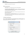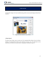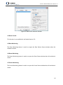
1
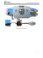
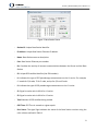
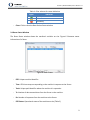
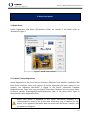
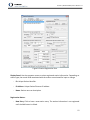
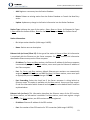
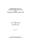
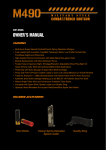
 SteerVu™ (BaseVu Module) User’s Manual v1.1 20 Barrett Court Fredericton, NB, Canada E3B 6Y1 www.gemini‐navsoft.com 2 SteerVu™ (BaseVu Module) User’s Manual v1.1 Contents Contents .......................................................................................................................................... 3 1. Description .................................................................................................................................. 4 2. BaseVu Layout ............................................................................................................................. 6 2.1 Base Server Software Window ................................................................................................. 6 2.2 Server Status Window .............................................................................................................. 7 2.3 Base Station Status Window ..................................................................................................... 7 2.4 Rover Status Window ................................................................................................................ 9 3. Menu Descriptions .................................................................................................................... 11 3.1 Mode Menu ............................................................................................................................ 11 3.1.1 Mode | Station Registration ................................................................................................ 11 3.1.2 Mode | Admin ID/Password ................................................................................................ 14 4. Main Interface ........................................................................................................................... 15 4.1 Base Control ............................................................................................................................ 15 4.2 Rover Control .......................................................................................................................... 16 4.3 Base Monitoring ...................................................................................................................... 16 4.4 Rover Monitoring .................................................................................................................... 16 4.5 Server Monitoring ................................................................................................................... 16 3 SteerVu™ (BaseVu Module) User’s Manual v1.1 1. Description SteerVu™ provides the GNT auto‐steering logic controller with high‐accuracy, high‐performance GPS navigation solutions and attitude information. SteerVu™ steers vehicles such as rubber‐
tired gantry (RTG) cranes, cargo transport vehicles, lawn mowers and tractors using a “map and match” mode of operation. SteerVu™ is designed for use in repetitive navigation applications. SteerVu™ consists of a Base Server (BaseVu) and a Rover Client (RoverVu). BaseVu is connected with one or more GPS Base Stations. BaseVu receives raw GPS observations from the Base Station(s) in real‐time. The status of the Base Station(s) is constantly monitored. RoverVu is installed on a vehicle and is connected with BaseVu. Upon receiving a request from RoverVu, BaseVu transmits the raw GPS observations received from the Base Station(s) to RoverVu. Map and match programming allows a human operator to map a navigation path by driving the vehicle over the path to be matched while RoverVu is in “map” mode. During map mode, RoverVu records and stores GPS positioning data which allows RoverVu to autonomously reproduce the mapped path. Multiple paths can be mapped and stored for a project site. Each path is uniquely defined by the GPS coordinates within the path. Navigation paths are stored locally in RoverVu memory and can be downloaded to a removable USB flash memory drives. With the navigation paths stored, the vehicle is capable of retracing the mapped paths whenever necessary. When the vehicle is in the vicinity of the desired path, the operator can select the desired navigation path to be matched from a list of paths saved for the site in RoverVu memory. Once the path has been selected and connection to BaseVu has been achieved, the operator moves the vehicle near the start of the navigation path. The operator then places the vehicle in automatic operation mode and the vehicle enters the navigation path, moving to the desired locations automatically. The GPS RTK (Real‐Time Kinematic) technique allows the vehicle to know precisely where it is on the surface of the earth to a positional accuracy of better than one inch. Under purely robotic control, the vehicle will wander off course due to errors caused by wheel slippage, uneven terrain, and other mechanically‐induced errors. RoverVu makes use of its GPS RTK navigation solutions and attitude information to correct for errors in the vehicle control system. In typical conditions where satellite visibility is favourable and the vehicle is well calibrated, the navigation path can be tracked to better than plus or minus two inches. A typical field setup of SteerVu™ is illustrated in Figure 1. 4 Figure 1: SteerVu™ field setup SteerVu™ (BaseVu Module) User’s Manual v1.1 5 SteerVu™ (BaseVu Module) User’s Manual v1.1 2. BaseVu Layout BaseVu comprises four sub‐windows as illustrated in Figure 2, including Base Server Software, Server Status, Base Station Status and Rover Status. Figure 2: BaseVu layout 2.1 Base Server Software Window As shown in Figure 3, the Base Server Software window is the main window of BaseVu. The menu system is used to access the utilities for Base or Rover station registration, and user authorization (see Section 3. Menu Descriptions). The utilities associated with user actions are activated through the button system (see Section 4. Main Interface). 6 SteerVu™ (BaseVu Module) User’s Manual v1.1 Figure 3: Base Server Software window 2.2 Server Status Window The Server Status window displays main activities on the Server computer such as Internet connection information of the Server, Base Stations and Rovers, and user actions on the Server as shown in Figure 4. This information is logged in the Server database. Figure 4: Server Status window 2.3 Base Station Status Window The Base Station represents the GPS receiver/antenna that is used for recording GPS data at a fixed, known geographical location. Figure 5 illustrates status information of a Base Station. 7 Figure 5: Base Station Status SteerVu™ (BaseVu Module) User’s Manual v1.1 − Station ID: Unique Base Station identifier. − IP Address: Unique Base Station Ethernet IP address. − Name: Base Station name or description. − Port: Base Station Ethernet port number. − Rx: Visualizes the activity of Internet communications between the Server and the Base Station. − SV: Unique GPS satellite identifier (the PRN number). − L1: Indicates the type of GPS pseudorange measurement on the L1 carrier. For example, c* stands for C/A‐code, *P for P‐code, and cp for C/A and P‐code. − L2: Indicates the type of GPS pseudorange measurement on the L2 carrier. − S1: Signal‐to‐noise ratio in dB‐Hz for L1 carrier. − S2: Signal‐to‐noise ratio in dB‐Hz for L2 carrier. − Total: Number of GPS satellites being tracked. − GPS Time: GPS Time in seconds at a given epoch. − Rcvr Status: The signal light indicates the status of the Base Station receiver using the color scheme outlined in Table 1. 8 SteerVu™ (BaseVu Module) User’s Manual v1.1 Table 1: Color scheme for status indication Signal Indication Healthy Unknown Unhealthy − Close: Click to close the Base Station Status window. 2.4 Rover Status Window The Rover Status window shows the machine’s activities on site. Figure 6 illustrates status information of a Rover. Figure 6: Rover Status − RTG: Unique machine identifier. − Time: GPS time stamp corresponding to the machine’s response to the Server. − Track: Unique path identifier where the machine is in operation. − Tx: Number of data transmissions from the Server to the machine. − Rx: Number of responses from the machine to the Server. − RTG Status: Operational status of the machine on site (Table 2). 9 SteerVu™ (BaseVu Module) User’s Manual v1.1 Table 2: Machine’s operational status Status Indication Unknown The status of the machine is unknown. No RTK The machine is active but GPS is not ready. GPS auto‐steering is ready for action but the RTK, No Auto‐steering operator has not activated it yet. RTK, Auto‐steering GPS auto‐steering is in action. Disconnection The machine is being shut down. requested − Number of RTGs on the Server: Number of the machines connected to the Server. − Close: Click to close the Rover Status window. 10 SteerVu™ (BaseVu Module) User’s Manual v1.1 3. Menu Descriptions 3.1 Mode Menu Station Registration and Admin ID/Password utilities are located in the Mode menu as illustrated in Figure 7. Figure 7: Mode menu utilities 3.1.1 Mode | Station Registration Station Registration is the one of the core functions of BaseVu. Once BaseVu is installed on the Base Server computer, users must register all devices associated with each station on the network. The registered information is logged in the Station Information Database (StationIPList.sta). Users must copy the Station Information Database into the system folder (C:\Gemini Navsoft Technologies\RoverVU\Application Data) of the Rover Client. Figure 8 illustrates the Station Registration form. Before each device is registered in the Station Information Database, it is recommended for users to set up the same information (e.g., IP address) for the device. If the registered information does not match with the device, SteerVu™ will not perform as designed. 11 SteerVu™ (BaseVu Module) User’s Manual v1.1 Figure 8: Station Registration form Display Panel: Use the computer mouse to select registered station information. Depending on station type, the record fields associated with the station are activated for input or change. − ID: Unique Station identifier. − IP Address: Unique Station Ethernet IP address. − Name: Station name or description. Registration Button: − New Entry: Click to have a new station entry. The station information is not registered until the Add button is clicked. 12 SteerVu™ (BaseVu Module) User’s Manual v1.1 − Add: Registers a new entry into the Station Database. − Delete: Deletes an existing station from the Station Database or Cancels the New Entry action. − Update: Updates any change in the Station information into the Station Database. Station Type: Indicates the type of the station – Base, Rover or Server. As illustrated in Figure 1, Base stands for the Base Station, Rover for the Rover Client, and Server for the Base Server. Station Information: − ID: Unique station identifier (Valid range: 0‐4095). − Name: Station name or description. Ethernet Info (on Server/Client PC): If the type of the station is Server or Base, this information is associated with the Ethernet on the Server computer. For Rover stations, this information describesthe Ethernet setup on the Client computer. − IP Address: For Server and Base stations, the Ethernet IP address of the Server computer is automatically assigned. For Rover stations, users must input the Ethernet IP address of the Client computer. − Port: For Server and Base stations, default Ethernet port numbers are automatically assigned (e.g., 10000 for Server and 8000 for Base). For Rover stations, users must input an appropriate port number (Valid range: 0‐65535). − Port Forwarding: Select the check box if the Server computer is sitting behind an Ethernet router. This option is available only for Base stations. Users must input router’s IP and Port information which forwards incoming packets to the default Base IP and Port explained above. Ethernet Info (on Peer): This information describes the Ethernet setup of the GPS receiver. For Server stations, no information is available. For Base stations, users must register a single GPS receiver. For Rover stations, two GPS receivers must be registered. − IP Address: Ethernet IP address of the GPS receiver. − Port: Port number of the GPS receiver for TCP connection (Valid range: 0‐65535). 13 SteerVu™ (BaseVu Module) User’s Manual v1.1 − Password: User password for TCP connection. GPS Receiver/Antenna Panel: − Antenna Type: Select the installed antenna from the Antenna Database. − Survey Mark Coordinates (WGS‐84 ECEF): This option is available only for Base. Users must input the fixed, known Base Station coordinates (X, Y, Z), expressed by the WGS‐84 Earth‐Centered‐Earth‐Fixed coordinate system. − Antenna Reference Point (ARP): Height from the mark on the ground or structure to the bottom of the GPS antenna. − Baseline Length Between Two GPS Antennas (m): This option is available only for Rover. If the fixed length of the baseline between two GPS antennas installed on the machine is known, users can input the value. 3.1.2 Mode | Admin ID/Password Users can change the Administrator’s ID and Password any time as illustrated in Figure 9. To access this utility, authorization is required through Old Security Code Validation. Once authorized, users can register a new ID and Password. Figure 9: Administrator’s ID and Password form 14 SteerVu™ (BaseVu Module) User’s Manual v1.1 4. Main Interface As illustrated in Figure 10, Control and Monitoring utilities are accessed through the Base Server interface. Figure 10: Main interface for user actions 4.1 Base Control The Base Control allows users to select one of the registered Base Stations from the Station Database. The selected Base Station serves the Rovers running on site. The information of the Base Station and Ethernet communications is displayed as illustrated in Figure 11. 15 SteerVu™ (BaseVu Module) User’s Manual v1.1 Figure 11: Base Station Selection window 4.2 Rover Control This function is not available for the BaseVu Version 2.0. 4.3 Base Monitoring The Base Monitoring button is used to re‐open the Base Station Status windows when this window is closed. 4.4 Rover Monitoring The Rover Monitoring button is used to re‐open the Rover Status window when this window is closed. 4.5 Server Monitoring The Server Monitoring button is used to re‐open the Server Status window when this window is closed. 16