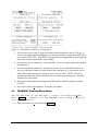
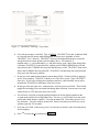
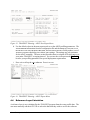
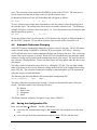
1
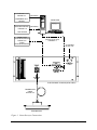
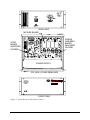
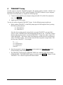
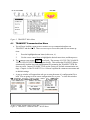
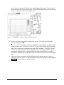
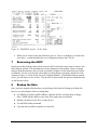
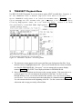
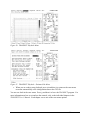
RD Instruments
Acoustic Doppler Current Profilers
Ocean Surveyor
User’s Guide
RD INSTRUMENTS
9855 Businesspark Ave.
San Diego, California 92131
(619) 693-1178
FAX (619) 695-1459
Internet [email protected]
Field Service - [email protected]
FTP - ftp.cts.com/pub/rdifs
http://www.rdinstruments.com
Copyright © 1998 by RD Instruments - All rights reserved.
Except as permitted under the copyright act of 1976, no part of this publication may be reproduced or distributed in
any form or by any means, or stored in a data base or retrieval system, without the prior written permission of RD
Instruments. This manual is licensed for use with RD Instruments products only.
P/N 95A-6002-00 (September 1998)
Table of Contents
1
Introduction........................................................................................................................1
2
Setup the ADCP .................................................................................................................1
3
System Interconnection....................................................................................................2
4
4.1
4.2
4.3
4.4
4.5
4.6
4.7
4.8
4.9
TRANSECT Setup ..............................................................................................................6
TRANSECT Communication Menu .....................................................................................7
TRANSECT Calibration Menu Setup.................................................................................11
TRANSECT Planning Menu Setup....................................................................................13
Reference Layer Calculation .............................................................................................15
Automatic Reference Changing.........................................................................................16
Saving the Configuration File.............................................................................................16
Sample TRANSECT Configuration File.............................................................................17
Using NAVSOFT with TRANSECT....................................................................................19
NAVSOFT Enhancements.................................................................................................19
Variable Field Length Decoding.........................................................................................19
Averaging Interval Change ................................................................................................20
5
Deploy the ADCP .............................................................................................................21
5.1 Physical Inspection ............................................................................................................21
5.2 Vessel Mount Special Considerations ...............................................................................22
5.3 Test the ADCP...................................................................................................................23
6
Using Transect to Collect Data ......................................................................................23
6.1 Setting the Time ................................................................................................................23
6.2 Collecting Data ..................................................................................................................24
6.3 TRANSECT Acquire Menu Setup......................................................................................24
7
Recovering the ADCP......................................................................................................26
8
Backup the Data ..............................................................................................................26
9
TRANSECT Playback Menu ............................................................................................27
10
Using NAVMERGE ...........................................................................................................29
NAVMERGE Parameters ..............................................................................................29
Required Parameters ...................................................................................................29
Optional Parameters.....................................................................................................29
Examples ......................................................................................................................30
10.2 NAVMERGE Syntax Rules............................................................................................30
10.3 Tabular Output Data......................................................................................................31
10.4 GPS Time......................................................................................................................31
10.5 Exiting NAVMERGE ......................................................................................................31
10.6 Adding Navigation Data to TRANSECT Processed Data Files.....................................32
10.1
11
11.1
11.2
11.3
11.4
11.5
11.6
12
Using BBLIST...................................................................................................................33
Starting BBLIST.............................................................................................................33
BBLIST Menus ..............................................................................................................33
Using BBLIST to Convert Files......................................................................................34
Using a BBLIST Format File to Convert Files ...............................................................35
Report File.....................................................................................................................38
BBBATCH Program ......................................................................................................39
Preparing the ADCP for Storage ....................................................................................39
List of Figures
Figure 1. Ocean Surveyor Connections...........................................................................................4
Figure 2. Ocean Surveyor Electronics Chassis ...............................................................................5
Figure 3. TRANSECT Main Menu ...................................................................................................7
Figure 4. TRANSECT Communication - ADCP Menu.....................................................................7
Figure 5. TRANSECT Communication - Ensemble Out Menu........................................................9
Figure 6. TRANSECT Communication - Navigation Menu..............................................................9
Figure 7. TRANSECT Communication - External Menu ...............................................................10
Figure 8. TRANSECT Communication - Reference Out Menu .....................................................10
Figure 9. TRANSECT Communication - Summary Menu .............................................................11
Figure 10. TRANSECT Calibration - Offsets Menu .......................................................................12
Figure 11. TRANSECT Calibration - Scaling Menu.......................................................................13
Figure 12. TRANSECT Planning - Setup Menu ............................................................................14
Figure 13. TRANSECT Planning - ADCP Non-Expert Menu.........................................................15
Figure 14. TRANSECT Planning - ADCP Expert Menu ................................................................15
Figure 15. Beam Clearance Zone .................................................................................................22
Figure 16. TRANSECT Acquire - Info Screen ...............................................................................24
Figure 17. TRANSECT Acquire - Data Collection Screen.............................................................25
Figure 18. TRANSECT Acquire - Scales Menu.............................................................................26
Figure 19. TRANSECT Playback - Processing Menu ...................................................................27
Figure 20. TRANSECT Playback Menu ........................................................................................28
Figure 21. TRANSECT Playback - Estimate Side Menu ...............................................................28
Figure 22. BBLIST Display ............................................................................................................34
Figure 23. Set the Processing Parameters....................................................................................36
Figure 24. Set the Conversion Limitations and Parameters ..........................................................36
Figure 25. Define Format Selection Menu.....................................................................................37
Figure 26. Defining the Format......................................................................................................37
Figure 27. View the Format before Converting..............................................................................37
1
Introduction
Thank you for purchasing the RD Instruments (RDI) Ocean Surveyor Acoustic Doppler Current
Profiler (ADCP). This booklet is designed to help first time ADCP users to unpack, set up, test,
and send deployment commands to their ADCP.
This booklet should be used with the Ocean Surveyor Technical Manual. Where needed, there
are references to detailed information and figures contained in the Ocean Surveyor Technical
Manual. For example, the reference (Figure A-1) would be found in the Ocean Surveyor Technical Manual in Appendix-A.
Ocean Surveyor vessel-mount deployments are Real-Time. Real-Time use refers to the fact you
are viewing the data as the ADCP collects it via a personal computer. This data is also stored on
the computer to allow for data playback and processing at a later time.
2
Setup the ADCP
As a minimum, you need the following equipment to set up the Ocean Surveyor system (see
Figure 1).
NOTE. Cable descriptions referenced figures are shown in Appendix-A of the Ocean Surveyor
Technical Manual.
♦ Ocean Surveyor – Contains the beam former transducer circuitry and optional TCM2
compass.
♦ Electronics Chassis
1. Contains all interfaces to/from the ADCP, computer/terminal, vessel gyros, and
power.
2. Allows either RS-232 (< 50 m) or RS-422 (> 50 m) computer-to-ADCP communications.
3. Converts vessel-gyro heading and tilt analog signals into digital data to be used for
ADCP heading, pitch, and roll. Our TRANSECT program supports this data. The
string format of the optional gyro-signal output from the electronics chassis is:
$PRDID, ±ppp.pp, ±rrr.rr, hhh.hh (where p is pitch, r is roll, and h is heading; all
scaled in degrees).
♦ Transducer Cable – Connects the ADCP transducer to the main signal-processing electronics chassis (Figure A-3).
♦ Serial Cable – RS-232 (J4) or RS-422 (J3) from the electronics chassis to the computer/terminal (Figure A-4).
♦ Computer – A computer running a terminal emulator programsuch as RDI’s BBTALKor a
real-time processing program such as TRANSECT. Recommended minimum requirements for the computer: 80386 CPU, 18-MHz clock speed, EGA monitor, hard drive, and
floppy drive. RDI programs support the following communication ports:
Ocean Surveyor User’s Guide
1
(1). COM1, IRQ4, addresses 3F8 through 3FF
(3). COM3, IRQ5, addresses 3E8 through 3EF
(2). COM2, IRQ3, addresses 2F8 through 2FF
(4). COM4, IRQ7, addresses 2E8 through 2EF
You also can connect the following equipment:
♦ External Gyrocompass – Supplies synchro/stepperheading information and/or synchro
pitch and roll information to the chassis for conversion before transmission to the computer for processing. Chapter 7 lists gyro requirements.
♦ External Navigation Device – Supplies serial, ASCII navigation data to the computer
(Figure A-6) via our TRANSECTand NAVSOFTprograms. See the TRANSECT manual
for requirements. This is an option for some ADCP applications. Users working in areas
where bottom-track detection is not possible need this equipment in order to remove
ADCP (Ship) motion from the data.
♦ External Ensemble-Out Device – Receives serial, ASCII ensemble data from the computer (Figure A-7) via our TRANSECT program. See the TRANSECT manual for requirements. This is an optional output from TRANSECT. This can be used to send
ADCP data to other equipment on the ship.
3
System Interconnection
Use Figure 1 and Figure 2, and the following steps to connect the system.
a. Turn OFF or disconnect all power to all ADCP system equipment.
CAUTION. Check the I/O cable and connector carefully for water before applying power. Even
a small amount of water in the connector will cause serious damage to the ADCP.
When connecting the I/O cable to the ADCP, do not over tighten the connector. The watertight
seal is achieved by the o-rings on the bore and face of the connector. This seal does not require
extreme force. Never use tools to tighten the connector.
b. Use Figures 2 and 3 to connect the ADCP I/O cable, electronics chassis, RS-232/422 serial cable, computer/terminal, and gyro equipment.
c. Apply power to all equipment. The electronics chassis accepts input voltages of 85-264
VAC. The electronics chassis automatically scales the input voltage to the proper level.
No special jumper/switch settings are required to select the input voltage.
CAUTION. Complete the ground path. The cord and the outlet used must have functional
grounds.
CAUTION. The transducer connector has transient RF pulses of one kilowatt. Do not operate
the equipment without the transducer cable and transducer or a protective cover installed. Do
not mate or unmate the transducer connector with power applied to the instrument.
2
RD Instruments
CAUTION. Do not obstruct access to the power cord. If the system is rack mounted, the rear of
the rack should be open and accessible.
CAUTION. The chassis may receive power from multiple sources. The main power cord and the
synchro/stepper connector must both be disconnected before opening the electronics unit.
d. Set up the communications protocol using BBTALK. Here are the ADCP default settings,
but you can use others (see Appendix-C, CB-command).
(1)
Baud rate - 9600
(3)
Stop bits - 1
(2)
Parity - None
(4)
BREAK length - 300 ms
Ocean Surveyor User’s Guide
3
TO ENSEMBLE-OUT
FIGURE A-7
(OPTIONAL)
ENSEMBLE-OUT
DEVICE
COMPUTER
OCEAN SURVEYOR
RD INSTRUMENTS ( C) 199 7-98
ALL RIGHT S RESERVED
>
FROM NAV DEVICE (OPTIONAL)
FIGURE A-6
NAV DEVICE
FROM GYRO
SYNCHRO/STEPPER
FIGURE A-5
GYRO
SYNCHRO/STEPPER
SERIAL CABLE
(RS-232 or RS-422)
FIGURE A-4
AC POWER
85-264 VAC
ELECTRONICS CHASSIS (REAR VIEW )
TRANSDUCER
CABLE
FIGURE A-3
TRANSDUCER
Figure 1. Ocean Surveyor Connections
4
RD Instruments
REAR VIEW
MOTHER BOARD
POWER
ASSEMBLY
BOARD
(MOUNTED
ON SIDE)
GYRO
BOARD
(MOUNTED
ON SIDE)
POWER SUPPLY
TOP VIEW (COVER REMOVED)
FRONT VIEW
Figure 2. Ocean Surveyor Electronics Chassis
Ocean Surveyor User’s Guide
5
4
TRANSECT Setup
Use this section to setup the TRANSECT program. We assume you have created a “default” configuration file to operate your ADCP with the installed TRANSECT software on your computer.
If you have not already done so, complete the following steps.
a. Connected your ADCP to your computer using serial (RS-232 or RS-422) communications. See Figure 1.
b. Applied power to the system.
You are now ready to begin the TRANSECT setup. Use the following steps to guide you.
a. Before running TRANSECT, at the DOS prompt type the following three lines, pressing
the Enter key after each one:
set AUTOSAVECFG=Y
set AUTOLOADCFG=Y
set AVGNAVVELS=Y
Since the above setting must be entered before you start TRANSECT, you may find it
easier to create a batch file that would automatically do this for you. To do this, return to
the drive/directory from where you started TRANSECT. Using a text editor, create a file
called ADCP.BAT. The first two lines of the batch file switch to the drive and directory
where TRANSECT resides. The next lines turns ON the navigation average feature. The
last line starts TRANSECT. For example:
C:
CD C:\RDI
set AUTOSAVECFG=Y
set AUTOLOADCFG=Y
set AVGNAVVELS=Y
TRANSECT
b. Start the program by entering TRANSECT (color monitor) or TRANSECT/M (monochrome monitor) at the DOS prompt.
c. The TRANSECT shell program (TRANSECT.EXE) now loads the main menu module
(TRMAIN.EXE). The MAIN MENU appears on your screen (Figure 3). Chapter 3 in the
TRANSECT User’s Manual explains this menu in detail.
6
RD Instruments
Figure 3. TRANSECT Main Menu
4.1
TRANSECT Communication Menu
a. You will now load the COMMUNICATION menu to set up communication between
TRANSECT and the ADCP. There are two ways to access this (and all) MAIN menu options.
1.
Press the highlighted menu letter (in this case, C).
2.
Use the cursor control keys to highlight the desired menu item, and then press e.
b. The COMMUNICATION menu (Figure 4) now loads. The message NO CFG FILE LOADED USING DEFAULT SETTINGS may appear briefly. This means that TRANSECT did not
automatically load the last-used configuration file (assuming the TRANSECT.PTR file
does not exist). Instead, TRANSECT will use the factory-set, default communication settings. Chapter 4 of the TRANSECT User’s Manual explains the COMMUNICATION menu and
its default settings.
c. A pop-up window will appear that asks you to enter the name of a configuration file to
load. You are going to create a new configuration file, so press ^ to close this window.
Figure 4. TRANSECT Communication - ADCP Menu
Ocean Surveyor User’s Guide
7
d. The COMMUNICATION menu has six submenus (the ADCP submenu is the one currently displayed). The top line on the screen lists the names of these submenus (ADCP, ENSEMBLEOUT, NAVIGATION, EXTERNAL, SUMMARY, EXIT). We want to access the ADCP submenu.
e. You will now set up communications with your ADCP. Move the cursor to within the
ADCP COMMUNICATION box to set the ADCP PORT, BAUD RATE, PARITY, STOP BITS, and DATA BITS
fields to match the ADCP settings. Highlight the desired field, and then press k to
change the field. Now highlight the VERIFY COMMUNICATION option and press e.
f. TRANSECT now tries to talk to the ADCP using the displayed settings. If successful, the
ADCP STATUS box displays ADCP COMMUNICATION ESTABLISHED. The dumb terminal window (lower half of screen) also shows the output from the ADCP. If you cannot
wake up the ADCP, or get an ADCP WAKE-UP ERRORS REPORTED message, see
step (g).
g. If you do not know the ADCP port settings, or if you cannot wake the ADCP using the
VERIFY COMMUNICATION option, select the AUTOMATIC CONNECT option. This option automatically searches for, and checks, the ADCP communication port settings. This process
may take several minutes, especially if the ADCP is set at a lower baud rate. If successful, the ADCP STATUS box displays ADCP COMMUNICATION ESTABLISHED. If you still
cannot talk to the ADCP, use the Ocean Surveyor Technical Manual to begin troubleshooting procedures.
h. After setting up communications with the ADCP, save the settings to a configuration
(CFG) file. Press m- SAVE (on bottom line of screen). A pop-up window asks you for a
file name. Enter the name DEFAULT (no extension needed). TRANSECT now saves the
communication port information to the file DEFAULT.CFG. The upper right corner of
the screen now shows the active drive and configuration file name. Note the other “hot
keys” at the bottom of the screen. If you want more information about these or any other
keys, press l- HELP.
i. If you needed to communicate to an ENSEMBLE-OUT aE (Figure 5), NAVIGATION aN (Figure
6), EXTERNAL SENSOR DEVICE aT (Figure 7), or REFERENCE-OUT DEVICE aR (Figure 8), the procedure would be similar to the one used for ADCP communications. For now, press aS
to display the SUMMARY submenu (Figure 9), which shows the communication settings to
all system devices. If necessary, you could make changes from here.
8
RD Instruments
Figure 5. TRANSECT Communication - Ensemble Out Menu
Figure 6. TRANSECT Communication - Navigation Menu
Ocean Surveyor User’s Guide
9
Figure 7. TRANSECT Communication - External Menu
Figure 8. TRANSECT Communication - Reference Out Menu
10
RD Instruments
Figure 9. TRANSECT Communication - Summary Menu
4.2
TRANSECT Calibration Menu Setup
You are now back in the MAIN menu. The upper left corner of the
screen shows the name of the configuration file (DEFAULT.CFG) now
loaded. Press B to load the CALIBRATION menu (Figure 3). Chapter 5
of the TRANSECT User’s Manual explains this menu in detail.
a. TRANSECT now tries to wake up the ADCP using the DEFAULT.CFG settings. If successful, TRANSECT reads ADCP clock and heading values. If not successful, either press
o-WAKE ADCP or return to the COMMUNICATION menu to reestablish communication. NOTE:
^ cancels the wake-up process.
b. Press aO to select the OFFSETS submenu (Figure 10).
Ocean Surveyor User’s Guide
11
Figure 10. TRANSECT Calibration - Offsets Menu
c. Go to the DEPTH OF TRANSDUCER FACE field. This field sets the distance of the transducer
face from the surface. Type in a value equal to the depth the ADCP transducer faces will
be below the surface in cm, but do not press e. If you now press ^, the field returns to its
previous value (0 cm). Instead, press the down arrow to go to the NEW ADCP TIME field.
Moving to a new field or pressing e automatically checks data validity in the current
field.
d. Enter the current date/time to the next minute. Go to the SEND NEW TIME option; press e
when the new time is reached to send the new time to the ADCP. TRANSECT displays
the new time in the ADCP TIME field. Note, the computer time is there for reference only.
It is not used by the ADCP or TRANSECT.
e. Set the TILT MISALIGNMENT OF, PITCH OFFSET, and ROLL OFFSET fields to zero degrees. For
systems with external tilt sensors, you would set these fields to account for mechanical
misalignment with the ship's centerline. Set them to zero degrees.
f. Set the TRANSDUCER MISALIGNMENT OF field to zero degrees. For systems with external tilt
sensors, you would set these fields to account for mechanical misalignment with the
ship's centerline. Set to zero degrees.
g. Go to the SET COMPASS OFFSET field. This setting corrects for electrical misalignment between the gyro and the ADCP’s Synchro Interface board. Enter a value of zero degrees.
h. Go to the MAGNETIC VARIATION field. This setting counteracts magnetic declination at the
deployment site. East values are negative; west values are positive. Enter the value in degrees to counteract your magnetic declination.
i. Press aS to select the SCALING submenu (Figure 11).
12
RD Instruments
Figure 11. TRANSECT Calibration - Scaling Menu
j. If the SALINITY VALUE is not 35.0 ppt, go to this field and change the value to 35.0 ppt. If
you are receiving pitch and roll inputs, go to the PITCH AND ROLL COMPENSATION field. Press
k to set this field to YES. TRANSECT uses pitch and roll compensation to map depth cell
data to the correct location in the water column.
k. Set SPEED OF SOUND to compute for every ensemble. Go to the COMPUTE FOR EVERY ENSEMBLE
bar and press e.
l. Set SOUND ABSORPTION COEFFICIENT, and ECHO INTENSITY SCALE to their default values. In
turn, go to the DEFAULT option in each of these boxes and press e. If you want to use another value, use the ENTER VALUE option to set in your own value. NOTE: The SOUND
ABSORPTION COEFFICIENT - DEFAULT field will ask you for the system frequency. Select the
frequency for your system.
m. If desired, set the DISCHARGE EXTRAPOLATION fields to their defaults (constant, constant,
0.16670).
n. Press aX to call the EXIT submenu. Select the
4.3
SAVE
option.
TRANSECT Planning Menu Setup
You are now back in the MAIN menu. Press L to load the PLANNING
menu (Figure 3). Chapter 6 of the TRANSECT User’s Manual explains
this menu in detail.
a. Press aS to select the SETUP submenu (Figure 12).
Ocean Surveyor User’s Guide
13
Figure 12. TRANSECT Planning - Setup Menu
b. Go to the DEPLOYMENT NAME field. Type in DEMO. TRANSECT uses this 4-character field
to create the data file names made during data collection (see Appendix-A in the
TRANSECT User’s Manual). TRANSECT also uses the deployment name to create the
storage directories on the primary and secondary drives. For example, if
PRIMARY DRIVE = C:, SECONDARY DRIVE = D:, and DEPLOYMENT NAME = DEMO, then during data
collection, TRANSECT creates data files with the prefix DEMO (DEMO####.###) and
stores them in the C:\DEMO directory until that directory is full. TRANSECT then writes
data to the D:\DEMO directory until full. TRANSECT will then stop data collection and
alert you to the disk space problem.
c. In turn, go to the PRIMARY DRIVE and SECONDARY DRIVE fields. Set these fields as appropriate for your computer. TRANSECT checks to see if the drive exists. If not, TRANSECT
alerts you. If you select a floppy drive that does not have a disk installed, it may take a
moment for TRANSECT to determine if the drive exists.
d. In turn, go to the RAW ADCP DATA, AVERAGED DATA, and NAVIGATION DATA fields. These fields
toggle the recording of the associated data during data collection. Set RAW ADCP DATA and
AVERAGED DATA to YES and NAVIGATION DATA to NO.
e. You will now select the averaging method and interval for the display updates in the
ACQUIRE menu and for the averaged data files. For now, we will average over time (temporal) rather than distance (spatial). Go to the METHOD field. If necessary, press k to select TEMPORAL. Go to the AVERAGE EVERY field. Enter a time that you wish to see screen
updates (typically 120 seconds).
f. Go to the UNITS field. If necessary, press k to select the SI (metric) units of measurement
for the displays.
g. Press aA to select the ADCP submenu (Figure 13).
14
RD Instruments
Figure 13. TRANSECT Planning - ADCP Non-Expert Menu
h. Use the default values in the non-expert mode to set the ADCP profiling parameters. The
ADCP HARDWARE information from the configuration file and the DEPTH CELL LENGTH, NO. OF
DEPTH CELLS MAX. BOTTOM DEPTH, SHIP SPEED, and LENGTH OF TRANSECT fields produce a set of
TRANSECT ESTIMATES that help you evaluate your settings. The settings are only estimates
for the ADCP ensemble. The next section describes how to calculate STD and range over
your entire TRANSECT averaging interval. You can use the aM-Expert mode (Figure 14)
to tailor your profiling parameters for special deployment requirements.
i. Press aX to call up the EXIT submenu. Press S to SAVE.
Figure 14. TRANSECT Planning - ADCP Expert Menu
4.4
Reference Layer Calculation
A reference layer is now calculated by the TRANSECT program from the water profile data. The
user must manually edit their CFG file to select the bins that they wish to use for the reference
Ocean Surveyor User’s Guide
15
layer. This selection is done inside the GRAPHICS section of the CFG file. The user must select the first bin and the last bin they wish to use for the reference layer.
By default the Reference Layer will be disabled and will appear as follows:
Ref_Layer
(
0
0
bin )
To set a reference layer simply enter a bin number in the first value to select the starting bin of
the reference layer. The second value selects the bin to end the reference layer. The following
example will select a reference layer from bins 4 - 10. Note, the reference layer includes the bins
entered and all bins between.
Ref_Layer
(
4
10
bin )
To use the reference layer you must use the ALT-R feature in the Acquire or Playback Menus of
the TRANSECT program. To turn off the reference layer set each of the values back to 0.
4.5
Automatic Reference Changing
TRANSECT can now automatically change the reference it uses for the data. The AUTO feature
can be selected during ACQUIRE or PLAYBACK by pressing the ALT-R keys. Selecting
AUTO will allow the user to switch automatically from one feature to the next. This switch only
occurs if the current reference is invalid. When AUTO is selected the user can determine which
reference is being used by looking at the bottom right corner of the screen. The letter for the correct reference is displayed there. Please note these letters will only update when the data is actually plotted.
The order of auto switch can be set by the user by editing the CFG file. The user must edit the
order of the letters in the Velocity Reference setting on the first line of the Graphic Menu setting
in the CFG file. The selection of automatic switching is done through the ALT-R command in
either the Acquire or Playback Menus.
The following line has been added to this section of the configuration file.
Velocity Reference (
AUTO
*GLNB* )
The order of the letters in between the asterisk (*) characters determine the order of the auto
switch. The letters stand for the following references:
B = Bottom
L = Water Layer
G = Navigation
N = None
The default selection is Bottom, Navigation, Layer, None (*BGLN*).
4.6
Saving the Configuration File
Press aX to call the EXIT submenu. You have four options.
16
♦
SAVE writes
♦
SAVE AS lets
the communication setup to the current CFG file, and then exits to the MAIN
menu.
you write the communication setup to a new CFG file, and then exits.
RD Instruments
♦
EXIT takes
♦
CANCEL
you to the MAIN menu without saving the setup.
(or ^) closes the EXIT submenu, but does not exit TRANSECT.
Press S to SAVE the setup.
4.7
Sample TRANSECT Configuration File
The following sample TRANSECT configuration file is included on the TRANSECT program
disk. The file name is osdef.cfg.
BEGIN RDI CONFIGURATION FILE
COMMUNICATIONS
{
ADCP
(
ENSOUT
(
NAV
(
REFOUT
(
EXTERNAL
(
}
ON
OFF
OFF
OFF
OFF
COM1
COM4
COM2
COM4
COM3
9600
9600
9600
4800
9600
N
N
N
N
N
8
8
8
8
8
1
1
1
2
1
)
)
)
)
)
[
[
[
[
[
Port
Port
Port
Port
Port
Baud
Baud
Baud
Baud
Baud
Parity
Parity
Parity
Parity
Parity
Databits
Databits
Databits
Databits
Databits
Stopbits
Stopbits
Stopbits
Stopbits
Stopbits
]
]
]
]
]
ENSEMBLE OUT
{
ENS CHOICE
( N N N N N N N N ) [ Vel Corr Int %Gd Status Leader BTrack Nav ]
ENS OPTIONS (BOTTOM
1
8
1
8 ) [ Ref First Last Start End ]
ENS TYPE
( RAW ) [ RAW (default) or AVERAGED data transmitted ]
}
ADCP HARDWARE
{
Firmware
Angle
Frequency
System
Mode
Orientation
Pattern
}
( 14.04 )
(
30 )
(
38 )
(
BEAM )
(
1 )
(
DOWN )
( CONVEX )
DIRECT COMMANDS
{
WS2400
WF600
BX30000
WN050
WD111100000
WP00001
BP000
WM1
WV650
TP000190
TE00000200
}
RECORDING
{
Deployment
Drive 1
Drive 2
ADCP
Average
Navigation
}
(
(
(
(
(
(
TEST )
C )
D )
YES )
YES )
YES )
Ocean Surveyor User’s Guide
17
CALIBRATION
{
ADCP depth
Heading / Magnetic offset
Transducer misalignment
Intensity scale
Absorption
Salinity
Speed of sound correction
Pitch & roll compensation
Tilt Misalignment
Pitch_Offset
Roll_Offset
Top discharge estimate
Bottom discharge estimate
Power curve exponent
Edge_slope coefficient
}
(
0.00 m
)
(
0.00
0.00 deg )
(
0.00 deg
)
(
0.43 dB/cts )
(
0.022 dB/m
)
(
35.0 ppt
)
(
NO
)
(
YES
)
(
0.00 deg
)
(
0.000 deg
)
(
0.000 deg
)
(
CONSTANT
)
(
CONSTANT
)
(
0.1667
)
( -1.00000 ) [-1=Trianglar(0.3535):-2=Square(0.91):User]
PROCESSING
{
Average every ( 120.00 s )
Depth sounder ( NO )
MaxFileSize ( 1200 )
Refout_info (
1
8 30.00 1.000 0
1) [bins:1st last, limit, weight, format,
delaysec]
External_formats ( N N Y N N ) [ HDT HDG RDID RDIE ]
External_decode
( Y Y Y N ) [ heading pitch roll temp ]
Start_Shore_distance ( -1 ) [ cm ]
End_Shore_distance
( -1 ) [ cm ]
Edge_distance_prompt ( NO )
}
GRAPHICS
{
Units
( SI )
Velocity Reference (
AUTO
*LGBN* )
Vessel
( NONE )
Ref_Layer
(
6
15
bin )
East_Velocity
( -25.0
25.0 cm/s )
North_Velocity
( -25.0
25.0 cm/s )
Vert_Velocity
( -10.0
10.0 cm/s )
Error_Velocity
( -10.0
10.0 cm/s )
Depth
(
1
40
bin )
Intensity
(
0
200
dB)
Discharge
( -1000
1000 m3/s )
East_Track
(
-100
100
m )
North_Track
(
-100
100
m )
Ship track
( 1 bin 100.0 cm/s )
Proj_Velocity
( -100.0 100.0 cm/s )
Proj_Angle
(
0.0 deg from N )
Bad_Below_Bottom
(
NO )
Line1
(
Line2
(
}
HISTORY
{
SOFTWARE
Version
}
)
)
( BB-TRANSECT )
( 3.03 )
END RDI CONFIGURATION FILE
18
RD Instruments
4.8
Using NAVSOFT with TRANSECT
The NAVSOFT program is used with TRANSECT to collect, store, and display navigation data.
NAVSOFT uses the program NAVCFG to create a configuration file to decode the navigation
data.
This section describes how to operate the NAVSOFT program within TRANSECT. Before starting TRANSECT, you must have created at least one valid .NAV file using the NAVCFG program
( N-5 in the TRANSECT User’s Manual). You also should have the TRANSECT program ready
for deployment, except for setting up NAVSOFT inside TRANSECT. If you have not yet set up
TRANSECT and created a TRANSECT configuration file (.CFG) for your deployment proceed as
follows.
a. Start TRANSECT and from the MAIN MENU, load the COMMUNICATION menu.
b. Press aN to go to the NAVIGATION submenu. Use the cursor keys to highlight the NAVSOFT
SOFTWARE INTERRUPT NUMBER. Enter a value from 242 to 255 (0F2h to 0FFh). A value outside this range disables the NAVSOFT interface. You do not need to set the serial port
settings in this menu because TRANSECT will use the settings set up in the NAVCFG
configuration file.
c. Press aA to go to the ADCP submenu. Set the NAVIGATION option to YES to enable
the navigation interface. TRANSECT is now set to “call” NAVSOFT during data collection.
d. EXIT the COMMUNICATION menu and SAVE your settings to a TRANSECT configuration file.
4.9
NAVSOFT Enhancements
Variable Field Length Decoding
The following features were included in version 3.23 of NAVSOFT.
The NAVSOFT program which is used to send navigation data to TRANSECT has had a feature
added that now allows it to decode the variable field lengths found in the $--VTG NMEA string.
The NMEA string $--VTG provides navigation speed over ground and course over ground. This
output is a better source for navigation speed and direction than the dead reckoning fix done in
earlier versions of NAVSOFT.
To use this new feature follow the normal setup instructions for the NAVCFG program. You
must still select Latitude, Longitude, and time the normal way. This is easiest to obtain out of the
NMEA $--GGA string. To select the speed and direction from the $--VTG line place the cursor
on the comma before the field. Selecting the comma will command the NAVCFG program to
decode the comma-delimited field preceding the comma you just selected. Note, this comma delimited feature is only applicable to the $--VTG line.
For this feature to work properly you must have at least 3 lines of NMEA data being transmitted
by the GPS device to the ADCP computer. The order of these three lines must not change. The
lines must be in this order $--GGA, followed by $--VTG and then any other NMEA line. There
can be other lines around these 3 lines but the order of these lines cannot change.
Ocean Surveyor User’s Guide
19
To start this properly you must be sure that the start delimiter is set to $--GGA and the end delimiter is set to the starting delimiter of the third line. For example, if the output format from
your navigation device had the following format:
$GPGLL,3401.070,N,13948.751,E
$GPGGA,054713,3401.070,N,13948.751,E,1,8,000,00011,M,0041,M
$GPVTG,336.0,T,336.0,M,014.7,N,027.3,K
$GPRMC,054713,A,3401.070,N,13948.751,E,014.7,336.0,130698,000.0,E*76
$GPZDA,054714,13,06,1998,-9
Your start delimiter is $GPGGA. Your end delimiter is $GPRMC. The lines $GPGLL and
$PGZDA will be ignored by the NAVSOFT program (but will still be captured by the TRANSECT
program in the navigation files).
Averaging Interval Change
The following features were included in version 3.20 of NAVSOFT.
The NAVSOFT program is used with TRANSECT to collect, store, and display navigation data.
NAVSOFT uses the program NAVCFG to create a configuration file to decode the navigation
data. NAVCFG has a feature that passes the velocity data (speed and direction) through a
smoothing filter. This filter helps smooth out some of the noise associated with navigation fixes.
The velocity output of this smoothing filter from NAVSOFT is what is sent to TRANSECT as the
navigation speed and direction. Note that the navigation Latitude and Longitude fixes that are
output from NAVSOFT are a simple average of all the fixes that come into NAVSOFT. These
averaged fixes are than sent from NAVSOFT to TRANSECT.
The latitude, longitude, and smoothed velocity data that TRANSECT receives are handled differently:
♦ The latitude and longitude values are accumulated until the user-selected averaging interval is reached; these values are then averaged before being written to the screen and to the
Processed data file.
♦ The smoothed velocity values are NOT accumulated. Each new smoothed velocity fix received overwrites the last smoothed velocity fix. This is because you cannot average
smoothed data points.
The navigation velocity data is used as a reference to remove vessel motion whenever you select
the navigation data as a reference (ALT-R in the Acquire or Playback menus). Since the
smoothed velocity data is only the last fix read by TRANSECT, this data may not represent the
actual velocity of the ship over the user-selected averaging interval.
Because of this, we have added a feature to disable the smoothing filter and allow TRANSECT to
do a straight average of the velocity data. The following explains how you must set up your
ADCP to use this feature. Please note that you must have TRANSECT version 2.80 or later to use
this new feature.
a. NAVCFG Changes. We must first disable the smoothing filter in the navigation configuration file. This is done through the NAVCFG program.
1.
20
Type NAVCFG at the DOS prompt.
RD Instruments
2.
You will be prompted to either create a configuration file or load an existing configuration file. If you already have a configuration file, enter “2” to load an existing configuration file. If you are creating a configuration file, use Appendix N
of the TRANSECT manual for help before continuing to step (3).
3.
Press the <Page Down> key until you are in the last window of NAVCFG and see
the entry for the VELOCITY FILTER WIDTH.
4.
The cursor will be next to the VELOCITY FILTER WIDTH window. Press the
space bar, and the cursor will move into the window. Enter “0” (zero).
5.
Press the <Esc> key to save the configuration and return to the main menu of
NAVCFG.
6.
Enter “0” (zero) to exit NAVCFG.
b. TRANSECT Changes. You now need to tell TRANSECT to average the navigation data
coming from NAVSOFT. This is done from the DOS prompt before you enter
TRANSECT. Do one of the following steps:
♦ Before entering TRANSECT, type in the following at the DOS prompt: SET
AVGNAVVELS=Y
♦ Since the above setting must be entered before you start TRANSECT, you may find it
easier to create a batch file that would automatically do this for you. To do this, return to the drive/directory from where you started TRANSECT. Using a text editor,
create a file called ADCP.BAT. The first two lines of the batch file switch to the
drive and directory where TRANSECT resides. The next line turns ON the navigation
average feature. The last line starts TRANSECT. For example:
C:
CD C:\RDI
SET AVGNAVVELS=Y
TRANSECT
5
Deploy the ADCP
At this point, you should have created a TRANSECT setup. You are now ready to deploy the
ADCP. The following steps will help guide you through the necessary steps for deploying the
ADCP.
5.1
Physical Inspection
Before using the ADCP, you must prepare the ADCP for deployment. Read Chapter 4 of the
Ocean Surveyor Technical Manual for detailed information on preparing the ADCP for deployment.
a. Before deploying the ADCP, you must consider its physical condition. Minor dents, corrosion, and missing paint may not seem crucial to the deployment, but could prove to be
damaging. Electrical continuity, the condition of the transducer faces, and watertight integrity are critical to the operation of the ADCP.
Ocean Surveyor User’s Guide
21
b. To help prevent shorts caused by condensation, you must let both the temperature and
humidity reach equilibrium.
c. Install the top hat end-cap on the ADCP transducer. Make sure all of the o-rings on the
waterproof I/O cable connector are installed.
d. Objects within about 100 meters (328 feet) of the surface are subject to biofouling. Softbodied organisms usually cause no problems, but barnacles can cut through the urethane
transducer face causing transducer failure and water leakage into the ADCP. If you are
deploying the ADCP in an area subject to biofouling, be sure you take steps to prevent
excessive growth of sea life on the transducer faces.
The ADCP measures water velocity along four, narrow, vertically inclined acoustic beams. For
accurate current measurements, the water mass in the deployment area must be free of strong
acoustic reflectors (e.g., platform members, large cables) within a 15° conical sector along each
beam. Figure 15 shows the clearance zone required for each beam.
TRANSDUCER
KEEP OBSTRUCTIONS OUT OF
THIS REGION, W HICH INCLUDES
A 15-DEGREE CONE AROUND
THE BEAM
Figure 15. Beam Clearance Zone
5.2
Vessel Mount Special Considerations
Use the following suggestions when mounting the ADCP to a moving platform.
♦ It is desirable to rigidly mount the ADCP to the vessel. You want to avoid the free spinning of the ADCP in this application. The ADCP must stay in the water at all times.
♦ The ADCP must be mounted deep enough so that turbulence caused by its movement
through the water does not allow air bubbles to be attached to the transducer faces.
♦ Avoid mounting the ADCP near motors and thrusters. They cause air bubbles and will
cause bias to the internal compass.
♦ Avoid mountings that will cause the ADCP to see severe accelerations.
22
RD Instruments
5.3
Test the ADCP
This section explains how to test the ADCP with RDI’s BBTALK program. These tests thoroughly check the ADCP in a laboratory environment, but are no substitute for a practice deployment. These tests do not calibrate the ADCP. You should test the ADCP:
♦ When the ADCP is first received.
♦ Before each deployment or every six months.
♦ When instrument problems are suspected.
♦ After each deployment.
These test procedures assume all equipment is working. The tests can help you isolate problems
to a major functional area of the ADCP. For troubleshooting information, see Chapter 6 of the
Ocean Surveyor Technical Manual. For help on using BBTALK, see Chapter 5 of the Ocean Surveyor Technical Manual.
Use the following steps to interconnect the ADCP system and to place the ADCP in a known
state.
a. Interconnect and apply power to the system as described in Figure 1.
b. Start BBTALK by typing BBTALKe.
c. Send PAe. You should see a message similar to the following.
>PA
RAM test...........PASS
ROM test...........PASS
6
Using Transect to Collect Data
TRANSECT is RDI’s real-time software data collection program. This program creates a configuration file to operate the ADCP, checks each command, and verifies that the ADCP has received the command. You have already done most of these steps, now it is time to perform the
final actions to begin collecting data.
6.1
Setting the Time
When you first start TRANSECT, you need to set the time so that both the ADCP’s and the computer’s time are synchronized.
a. Go to the CALIBRATION-OFFSETS menu.
b. Enter the current date/time to the next minute.
c. Go to the SEND NEW TIME option; press e when the new time is reached to send the new
time to the ADCP. TRANSECT displays the new time in the ADCP TIME FIELD.
d. The computer’s time is shown only as a reference and is not used by TRANSECT. However, if the computer’s time is not correct, exit TRANSECT, and set the computer’s time
using the DOS TIME command.
e. Return to the MAIN menu by pressing aX and save the configuration file.
Ocean Surveyor User’s Guide
23
6.2
Collecting Data
Use the ACQUIRE menu in TRANSECT to begin collecting data. Refer to the TRANSECT User’s
Manual for more information on how to use this program.
6.3
TRANSECT Acquire Menu Setup
At the MAIN menu, press A to load the ACQUIRE menu (Figure 3). Chapter 7 of the TRANSECT User’s Manual explains this menu in detail.
TRANSECT now tries to wake up the ADCP using the settings in the
CFG file. If successful, TRANSECT sends the profiling parameters
to the ADCP.
TRANSECT will “call” NAVSOFT'’s LOAD FILE MENU if you enabled the Navigation and NAVSOFT
interrupt number in the COMMUNICATION menu. Select the desired .NAV configuration file and
load it by pressing e. Now press ^ to return to the ACQUIRE menu. You can now operate
TRANSECT as you normally would except you have the added navigation features.
a. Review the displayed information screen (Figure 16). Most of this information is selfexplanatory, as it is a summary of the settings from the other menus and from the CFG
file. If a communication option and port information is in yellow letters (color) or has an
asterisk (monochrome), the communication for that item is active. TRANSECT will read
and record data for that communication port.
Figure 16. TRANSECT Acquire - Info Screen
b. The ADCP is now ready to collect data, but first we will review the layout of the display
window. Press ^ to display the data collection screen (Figure 17). The right side of the
screen shows the common data for each ensemble read from the ADCP. TRANSECT updates this area with each ADCP ensemble. This area also displays file information, the
24
RD Instruments
active drive, the amount of free disk space, and discharge information. The left side of
the screen shows the selected data display. TRANSECT updates this area at the end of the
AVERAGE EVERY interval set in the PLANNING menu.
Figure 17. TRANSECT Acquire - Data Collection Screen
c. Press aI to select ECHO INTENSITY contour plot options. Now press A to display the
AVERAGE of all four beams.
d. Press o-COLLECT to begin data collection. TRANSECT will not display real data if your
system is not in water. Note that as TRANSECT receives data from the ADCP, the right
side of the screen shows information from each ADCP ensemble. TRANSECT also records the raw data at this time. The averaging interval is 5.0 seconds, which means the
first transect segment will be completed when the elapsed time reaches 5.0 seconds.
TRANSECT will then make/update the display (plot) and record the processed (averaged)
data.
e. Take some time to experiment with the different display options (PROFILE, VELOCITY,
SHIPTRACK, TABULAR). Press ^ to see the alternate key options. Use q to scale the displays
(Figure 18). Use r to add a comment to the plot.
Ocean Surveyor User’s Guide
25
Figure 18. TRANSECT Acquire - Scales Menu
f. When you are ready to stop data collection, press o. Press aX and then Y to return to the
MAIN menu. ACQUIRE automatically saves configuration data to the CFG file.
7
Recovering the ADCP
Before proceeding with any other action, rinse the ADCP with fresh, soapy water to remove softbodied marine growth. This also helps prevent the formation of salt crystals. Remove foreign
material from the transducer faces as soon as possible (Chapter 4 of the Ocean Surveyor Technical Manual). Be sure to clean such critical places as the transducer assembly, and the I/O cable
connector (Figure 4-1 of the Ocean Surveyor Technical Manual). If hard-bodied marine growth
exists, you can remove it now or later. Dry the ADCP exterior with low-pressure compressed air
or soft lint-free towels.
8
Backup the Data
Once you have stopped collecting data, you should get in the habit of backing up all data files.
Here are several examples of how to backup data.
♦ Use PKZIP (available on RDI’s BBS) to condense the files and store them on floppy
disks. PKZIP has the ability to store large files (span) onto several disks.
♦ Backup your data to a tape drive or other device.
♦ Use the DOS backup command.
♦ Copy the data to another computer on a network.
26
RD Instruments
9
TRANSECT Playback Menu
Use RDI’s TRANSECT program PLAYBACK menu to replay ADCP recorded data. Chapter 8
of the TRANSECT User’s Manual explains this menu in detail.
Start TRANSECT and press P to load the PLAYBACK menu (Figure 3). The
first message on the screen asks you to press s to load your data
files by deployment name, or n to load any file. Press s to load
the previously recorded DEMO deployment (Figure 19).
Figure 19. TRANSECT Playback - Processing Menu
a. The PROCESSING menu appears on the screen and lists your deployment data files. Press
the down arrow to highlight transect 001. Press R (see bottom line on screen) to load the
raw data file DEMO001R.000. Now press ^ twice to return to the PLAYBACK display
menus (Figure 20). TRANSECT now displays the data for DEMO001R.000.
b. Most of the PLAYBACK options are the same as the ACQUIRE options. Take some time to experiment again. Use o to PAUSE/RESUME the playback of the data. Use the k to STEP
through the data. Press a to see the ALTERNATE KEY options. Use aA to create an ASCIIOUT DATA FILE. Use aE to ESTIMATE THE UNMEASURED SIDES of a channel transect (Figure 21).
Use aW to REWIND the data to the beginning of the file. Use the s-PROCESSING menu to
subsection and average previously collected data.
Ocean Surveyor User’s Guide
27
Figure 20. TRANSECT Playback Menu
Figure 21. TRANSECT Playback - Estimate Side Menu
c. When you are ready to stop playback, press aX and then Y to return to the MAIN menu.
PLAYBACK automatically saves configuration data to the CFG file.
You are now back in the MAIN menu. Press Q and then Y to leave the TRANSECT program. For
more information on how to set and use the controls, refer to the individual chapters in the
TRANSECT User’s Manual. Each chapter covers one of the MAIN menu options.
28
RD Instruments
10
Using NAVMERGE
NAVMERGE is a utility program that performs post processing of previously recorded raw navigation and TRANSECT processed ADCP data, and merges the navigation data into the processed
ADCP data file. Actually, a new processed data file is created leaving the original intact. The
new processed ADCP data file can then be played back into TRANSECT. The program can also
produce a tabular output of the processed navigation data in a format suitable for spreadsheet
analysis.
10.1 NAVMERGE Parameters
Access the drive/directory containing the NAVMERGE.EXE program and data files. The command to run NAVMERGE has the following format: navmerge parameters
Where parameters are the following:
Required Parameters
-Rname
-Rname specifies the raw navigation data file, e.g. -rDPLY000N.000, or the starting
file in a sequence.
-Cname
-Cname specifies the navigation configuration file, e.g. -cLORAN.NAV. This file is
obtained from the RDI NAVCFG program, and is a binary file that identifies the format of the raw navigation data. This file can have any name, but usually has the
.NAV extension.
-Pname
-Pname specifies the TRANSECT processed ADCP data file, for example: pDPLY000P.000, or the starting file in a sequence.
-Oname
-Oname specifies the output file, e.g. –oDPLY000.MRG, or whatever name you want
to give it.
Optional Parameters
-G
For those who need to decode navigation time data in GPS format. See explanation
below in the section titled, GPS TIME. Most customers will not use this option.
-Mname
Specifies the tabular output file, e.g. –mPNAV000.TAB, which is written in ASCII
format by NAVMERGE, so that the data may be easily loaded into a spreadsheet for
analysis. See description of tabular output below.
-S
Causes a sequence of raw navigation and processed ADCP data files to be processed.
-Ttau
Specifies a time constant for the velocity exponential smoothing filter. This value,
tau, will override the value in the navigation configuration file.
-?
Causes NAVMERGE to display the command line syntax and exits to DOS without
further processing.
Ocean Surveyor User’s Guide
29
The NAVMERGE program will display activity dots on the screen during processing to let the
user know that the program is working. Upon completion of the merging process, NAVMERGE
will return the user to the DOS prompt. When the ratio of raw navigation data points to processed
ADCP ensembles is high, the activity dots on the screen during the merge process will be slow. It
just means that more navigation data is being processed between the dots.
Examples
NOTE. The file names used in the following command lines are examples, where DPLY
represents a deployment name, the three digit number in the base name represents a transect
number, and the three digit number in the extension represents a sequence number.
To process a single file set, i.e. a single matched pair of raw navigation and TRANSECT processed ADCP data files, use the following format (of course, substitute your own file names):
navmerge -rDPLY000n.000 -cloran.nav -pDPLY000p.000 -oDPLY000.dat
If you want a tabular output of the processed navigation data, add the -M option, as follows:
navmerge -mPNAV000.TAB -rDPLY000n.000 -cloran.nav -pDPLY000p.000 -oDPLY000.dat
And if you want to process a sequence of files (i.e. consecutive file extension numbers with the
same base names), add the –S option to one of the previous command lines as follows:
navmerge -s -rDPLY000n.000 -cloran.nav -pDPLY000p.000 -oDPLY000.dat
This example will process the raw navigation data files DPLY000N.000 through
DPLY000N.005, for example, if there are six raw navigation data files in the sequence. Similarly, the sequence of TRANSECT processed ADCP data files, DPLY000P.000 through
DPLY000P.nnn will also be processed if nnn + 1 processed data files that exist. Processing stops
when either processed ADCP data or raw navigation data is exhausted.
10.2 NAVMERGE Syntax Rules
The ordering of the command line parameters is not significant, and the option letters may be upper or lower case. The dash character preceding the option letter is required (or it may be a forward slash, “/”) and there must be no intervening spaces between the “-“, the option letter, and
the filename introduced by that option. Parameters must be separated by one or more spaces, and
there must be one or more spaces between the program name and the first parameter.
30
RD Instruments
10.3 Tabular Output Data
If the -M option is used, an ASCII file is created by NAVMERGE and filled with the processed
navigation data.
A single title line appears on the first line of the file, identifying the fields. All other lines in the
file contain only numbers, i.e. the navigation data values. The field names are abbreviated, and
are as follows:
VSE
Smoothed East Velocity (m/s)
VSN
Smoothed North Velocity (m/s)
DSE
East Displacement (m)
DSN
North Displacement (m)
DIST
Total Distance Traveled (m)
MLAT
Mean Latitude (degrees)
MLON
Mean Longitude (degrees)
FILW
Filter width, or time constant used in the velocity-smoothing filter. This value is obtained from the navigation configuration file (i.e. the file produced by NAVCFG), unless specified on the command line with the -T option.
Each record of processed navigation data appears on a single line, with the fields listed in the order shown above. Commas separate fields. All data is in ASCII format, and the file may be edited with any text editor. A word processing program is not recommended for editing this file as
it may introduce non-ASCII control characters that will prevent the file from being properly interpreted by the analysis program (i.e. spreadsheet).
10.4 GPS Time
The RDI NAVCFG program, which is used to create the navigation configuration file, currently
does not allow decoding of GPS time format (i.e. GPS week number and Time-Of-Week) as it is
not one of the NMEA standard formats. This option has been added to tell NAVMERGE to treat
the “Julian Day” field as a GPS week number, and to treat the “Seconds” field as a GPS Time-ofWeek (i.e. seconds since midnight Saturday night/Sunday Morning). Most customers will not
use this option.
NOTE. Although NAVCFG will allow you to set up your time decoding in this way, it will fail to
decode the data because the values for seconds will be too large. Do not worry about the error
messages given by NAVCFG if you are just going to run NAVMERGE. NAVMERGE will properly
decode this data if the –G option is used.
10.5 Exiting NAVMERGE
NAVMERGE automatically exits to DOS when processing is complete.
Ocean Surveyor User’s Guide
31
10.6 Adding Navigation Data to TRANSECT Processed Data Files
The TRANSECT program can collect data in 3 different ways Raw ADCP data, Raw Navigation
data, and Processed data. Each of the files contains its own data structure.
The Raw ADCP data files contain the data as the ADCP sent it out to TRANSECT. This means
the data is in the ADCP data format. The description of this data format is found in the Ocean
Surveyor Technical Manual (Appendix-D).
The Raw Navigation data files contain the data as the navigation device sent it out to
TRANSECT. Additionally, there is a header in front of each block of navigation data that contains
an ADCP ensemble number and PC time. The PC time is not useful for most cases. The ADCP
raw ensemble number indicates that all data after this number was sent from the navigation device to TRANSECT during that particular ADCP ensemble. This allows you to link the raw
Navigation data to the raw ADCP data. The format of the navigation data in this file is the same
as what the navigation device sent out.
The Processed data (or average data) is the ADCP raw ensembles converted to earth coordinates
and averaged over the time period set by you in the Planning Menu of TRANSECT. This data also
can contain navigation data when TRANSECT is used with NAVSOFT. If NAVSOFT is not used
there will be no navigation data in the file. The format for the Processed data file is found in the
TRANSECT manual.
Sometimes you may wish to average your data over a different time period than when you originally collected the data. The only way to do this is to re-average the Raw ADCP data over a different time period in the Playback Menu. This data can then be stored in a new Processed data
file. However, it is not possible to average in the Raw Navigation data into this file through
TRANSECT. The only way this can be done is if you use the NAVMERGE program.
To add navigation data to a Processed data file use the following procedure.
a. Create a Processed data file with the Playback Menu of TRANSECT. You must use the F8
function key to save the data and set the averaging interval.
Note: if you have a Processed data file already and wish to overwrite the navigation data
in the file then just continue with the next step.
b. Use the program NAVMERGE to add the raw Navigation data to the Processed data file.
You must have the following to complete this task.
♦ Raw Navigation data created by TRANSECT
♦ A Navigation configuration file, i.e. *.nav (see notes below if you do not have one)
♦ A Processed Data file
If you need to create a navigation configuration file use the following steps.
32
1.
Copy your Raw Navigation data created by TRANSECT to a file named
DEMO.DAT.
2.
Run the program NAVDEMO. This program is provided with the NAVSOFT program and on the TRANSECT distribution disk.
RD Instruments
11
3.
Enter a 1 to select the option Configure Navigation interface. The Raw Navigation data file will now start to scroll on the screen. Follow the instructions on how
to create a configuration file for the NAVCFG program found in the TRANSECT
manual.
4.
After completion, save the file for use with NAVMERGE.
Using BBLIST
BBLIST takes the binary data files created by our ADCP and lets you convert selected data fields
to common units of measurement in an ASCII-text format. You can then use the ASCII files in
programs that accept this format. BBLIST never alters your original ADCP binary data files.
BBLIST lets you:
♦ Set processing parameters.
♦ Transform velocity data.
♦ Select the display/conversion limitations (e.g., data fields, bin range, ensemble range,
output file size).
♦ Select the ADCP data fields to display or convert.
♦ Monitor and control the conversion process.
♦ Look at radial beam data.
11.1 Starting BBLIST
To start BBLIST, do the following:
BBLISTe - Starts BBLIST and lets you select the ADCP binary data file from within the program.
BBLIST C:\BBDATA\TEST.000 /Me - Starts BBLIST and loads the TEST.000 file located on
the C: drive in the BBDATA directory. The /M forces BBLIST to use monochrome screens.
When you run the program the first time, BBLIST displays its introduction and copyright screen.
During operation, BBLIST creates/updates a pointer file named BBLIST.PTR. This file saves the
current working directory, the name of the last binary file used, the name of the format file
(*.FMT) last used, and the color selection. This may help save you time by automatically calling
up the files you used last. If you need to see the introduction screen again, you must first delete
or rename the BBLIST.PTR file.
Extensive help is available while using BBLIST by pressing l. The help screen lists all of the
menus and a description of each option available. You may also print the help screen file by
printing the file BBLIST.DOC.
11.2 BBLIST Menus
BBLIST has four main menus (Figure 22) to guide you through the steps needed to convert an
ADCP binary raw data file to an ASCII data file.
Ocean Surveyor User’s Guide
33
File Menu. Use this menu to save your menu settings and conversion layout selections to a configuration format file (*.FMT), to load a Ocean Surveyor binary data file or format file, to display
the file information screen, or to exit BBLIST.
Process Menu. Use this menu to set the processing parameters for BBLIST. You can set the
velocity reference, magnetic variation (declination), velocity measurement units, and depth
measurement units.
Display Menu. Use this menu to select the type of data to view. Data available for display include ADCP setup, sensors, reference layer, bottom-track, and profile.
Convert Menu. Use this menu to convert the binary ADCP data set into ASCII. Before starting
the conversion process, you can define the conversion limitations and the output format.
Figure 22. BBLIST Display
11.3 Using BBLIST to Convert Files
This is an example of how to convert the binary file EXAMPLE.000 to ASCII delimited text.
For this example, we have chosen to extract only the magnitude, direction, and range data. Remember that BBLIST never changes your original data file - you can convert the raw data to as
many different ASCII formats as desired.
Start BBLIST. To start BBLIST, type BBLISTe.
Load EXAMPLE.000 binary file. Press n to load the binary file.
Set the processing parameters. Use the PROCESS menu (Figure 23) to set the velocity reference,
magnetic variation, velocity measurement units, and depth measurement units. Use the k key to
toggle each setting.
Set the conversion parameters. Use the CONVERT, LIMITS menu (Figure 24) to set the conversion
limitations and parameters. You may want to increase the Max file size to 1000 kB if you plan to
back up the ASCII data to floppy disks.
Define the format. Consider the following:
34
RD Instruments
♦ What data do you want to extract? For this example, we choose magnitude, direction,
and range.
♦ What program will you export the ASCII data to? Does the program support space, tab,
or comma delimited text? We choose space delimited text for the example. To change,
select Field delimiter and press k to toggle between tab, comma, and space.
♦ Do you want vertical or horizontal placed data? For this example, we choose a vertical
data format. To change, select Bin layout and press k to toggle between vertical and horizontal.
Begin defining the format by doing the following;
a. Select CONVERT, DEFINE FORMAT. When you first enter this screen, BBLIST displays only
a FORMAT END marker. To begin entering data fields, press e to display the DEFINE
FORMAT selection menu (Figure 25). If you make a mistake, select delete block and reenter your choice.
b. Select ensemble info and press e. Select Number and press e.
c. Move the cursor to the FORMAT END marker and press e.
d. Select Profiles, Mag and Dir. Select M for magnitude and press e.
e. Move the cursor to LINE END and press e.
f. Select Profiles, Mag and Dir. Select D for direction and press e.
g. Move the cursor to LINE END and press e.
h. Select Profiles, Depth ref. Select R for range and press e. Your display should look like
Figure 26.
View the format. Press t to view the format before converting (Figure 27). Use the + and keys to increase the ensemble number. Press t again to return to the define format screen.
Save the format. Save the format to a *.FMT file for future use by pressing m and naming the
file (example; MYFORMAT).
Begin the conversion. Select CONVERT, START CONVERSION. Enter a file name for the ASCII
file data set. Be sure to use a file name that differs from any existing file name. Do not use
the name of the binary data set. If BBLIST detects that the file name already exists, you are given
the option to overwrite the existing files.
11.4 Using a BBLIST Format File to Convert Files
Start BBLIST. To start BBLIST, type BBLISTe.
Load EXAMPLE.000 binary file. Press n to load the binary file.
Load Format file. Press n to load the format file.
Begin the conversion. Select CONVERT, START CONVERSION. Enter a file name for the ASCII
file data set. Be sure to use a file name that differs from any existing file name. Do not use
Ocean Surveyor User’s Guide
35
the name of the binary data set. If BBLIST detects that the file name already exists, you are given
the option to overwrite the existing files.
Figure 23. Set the Processing Parameters
Figure 24. Set the Conversion Limitations and Parameters
36
RD Instruments
Figure 25. Define Format Selection Menu
Figure 26. Defining the Format
Figure 27. View the Format before Converting
Ocean Surveyor User’s Guide
37
11.5 Report File
When the conversion process is complete, BBLIST creates an ASCII report file (*.RPT). You
can view this file with any text editor. This file contains the following information about the settings and data in the converted files.
♦ ADCP information - system frequency, beam angle, number of profiling beams, transducer orientation (up/down), transducer pattern (concave/convex), transducer connection
(connected/disconnected), and CPU firmware version number
♦ ADCP setup - number of bins, bin length, blank after transmit length, pings per ensemble,
time per ping, and profiling mode.
♦ ASCII file data format - a description on the contents of each line in the converted data
file (for one ensemble).
♦ Processing parameters - velocity units, velocity reference, depth units, bin sequence,
magnetic variation.
Sample BBLIST report file:
REPORT FOR ASCII DATA CONVERSION
-------------------------------1. ADCP INFORMATION:
Frequency 300 kHz
Beam angle 20 deg
4 beam system
Up-looking orientation
Convex beam pattern
Transducer head connected
CPU firmware 8.01
2. ADCP SETUP:
Number of bins 15
Bin length 200 cm
Blank after transmit 200 cm
Distance to first bin 421 cm
Transmit length 207 cm
Pings per ensemble 300
Time per ping 1.99 s
Profiling mode 1
3. ASCII FILE DATA FORMAT:
Line 1: Ensemble number
Line 2-16: Magnitude , Direction, Bin range
4. PROCESSING PARAMETERS:
Velocity units: ADCP
Velocity reference: BT
Depth units: ADCP
Bins: From 128 to 1 skip 0 bin
Magnetic variation 0.00 deg
Do not mark data below bottom
END OF REPORT
-------------
38
RD Instruments
11.6 BBBATCH Program
When you have mastered the BBLIST program, you can use BBBATCH to convert binary data
sets to ASCII data sets in a DOS batch mode. This comes in handy when you have several data
sets to convert or have a large data set that you want to convert overnight. Here is the syntax for
BBBATCH:
BBBATCHkBinaryFileNamekFormatFileNamekAsciiFileName
♦ BinaryFileName = name of the binary data set to convert (no extension needed)
♦ FormatFileName = name of the format file to use
♦ AsciiFileName = name of the ASCII data set (unique name)
♦ Running BBBATCH without any command line parameters displays the syntax.
12
Preparing the ADCP for Storage
Before storing or shipping the ADCP, remove all foreign matter and biofouling. Remove softbodied marine growth or foreign matter with soapy water. Waterless hand cleaners remove most
petroleum-based fouling. Rinse with fresh water to remove soap residue. Dry the transducer
faces with low-pressure compressed air or soft lint-free towels.
CAUTION. The soft, thin urethane coating on the transducer is easily damaged. Do not use
power scrubbers, abrasive cleansers, scouring pads, high-pressure marine cleaning systems, or
brushes stiffer than personal hand cleaning brushes on the transducer.
If there is heavy fouling or marine growth, the transducer may need a thorough cleaning to restore acoustic performance. Barnacles do not usually affect ADCP operation. We do, however,
recommend removal of the barnacles to prevent water leakage through the transducer face. Lime
dissolving liquids such as Lime-Away break down the shell-like parts. Scrubbing with a medium stiffness brush usually removes the soft-bodied parts. Do NOT use a brush stiffer than a
personal hand cleaning brush. Scrubbing alternated with soaking in a lime dissolving liquid effectively removes large barnacles.
After using a lime dissolving liquid, rinse the ADCP with fresh water to remove all residues. If
barnacles have entered more than 1.0 1.5 mm (0.04 0.06 in.) into the transducer face urethane,
you should send the ADCP to us for repair. If you do not think you can remove barnacles without damaging the transducer faces, contact RDI.
Before storing the ADCP, you may want to cover the body of the ADCP with a light coat of a
high-viscosity silicone oil or grease to help prevent corrosion. Do NOT apply grease or oil to the
urethane transducer faces.
Ocean Surveyor User’s Guide
39
NOTES
40
RD Instruments