1
User’s Manual of WGSW-48000
User’s Manual
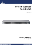
WGSW-48000
48-Port 10/100/1000Mbps with
4 Shared SFP
Layer 2 Managed Ethernet Switch
1
User’s Manual of WGSW-48000
Trademarks
Copyright © PLANET Technology Corp. 2009.
Contents subject to which revision without prior notice.
PLANET is a registered trademark of PLANET Technology Corp.
All other trademarks belong to their respective owners.
Disclaimer
PLANET Technology does not warrant that the hardware will work properly in all environments and applications, and makes no
warranty and representation, either implied or expressed, with respect to the quality, performance, merchantability, or fitness for
a particular purpose. PLANET has made every effort to ensure that this User's Manual is accurate; PLANET disclaims liability
for any inaccuracies or omissions that may have occurred.
Information in this User's Manual is subject to change without notice and does not represent a commitment on the part of
PLANET. PLANET assumes no responsibility for any inaccuracies that may be contained in this User's Manual. PLANET makes
no commitment to update or keep current the information in this User's Manual, and reserves the right to make improvements to
this User's Manual and/or to the products described in this User's Manual, at any time without notice.
If you find information in this manual that is incorrect, misleading, or incomplete, we would appreciate your comments and
suggestions.
FCC Warning
This equipment has been tested and found to comply with the limits for a Class A digital device, pursuant to Part 15 of the FCC
Rules. These limits are designed to provide reasonable protection against harmful interference when the equipment is operated
in a commercial environment. This equipment generates, uses, and can radiate radio frequency energy and, if not installed and
used in accordance with the Instruction manual, may cause harmful interference to radio communications. Operation of this
equipment in a residential area is likely to cause harmful interference in which case the user will be required to correct the
interference at whose own expense.
CE Mark Warning
This is a Class A product. In a domestic environment, this product may cause radio interference, in which case the user may be
required to take adequate measures.
WEEE Warning
To avoid the potential effects on the environment and human health as a result of the presence of
hazardous substances in electrical and electronic equipment, end users of electrical and electronic
equipment should understand the meaning of the crossed-out wheeled bin symbol. Do not dispose of
WEEE as unsorted municipal waste and have to collect such WEEE separately.
Revision
PLANET 48-Port 10/100/1000Mbps with 4 Shared SFP Combo Managed Switch User's Manual
FOR MODEL: WGSW-48000
REVISION: 1.0 (APRIL.2009)
Part No: EM-WGSW-48000 (2081-A93180-000)
2
User’s Manual of WGSW-48000
TABLE OF CONETNTS
1. INTRODUTION .................................................................................................................... 20
1.1 Packet Contents .........................................................................................................................................20
1.2 Product Description ...................................................................................................................................20
1.3 How to Use This Manual ............................................................................................................................21
1.4 Product Features........................................................................................................................................23
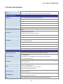
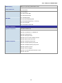
1.5 Product Specification ................................................................................................................................25
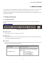
2. INSTALLATION ................................................................................................................... 27
2.1 Hardware Description ................................................................................................................................27
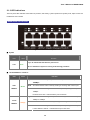
2.1.1 Switch Front Panel ..............................................................................................................................................27
2.1.2 LED Indications ...................................................................................................................................................28
2.1.3 Switch Rear Panel ...............................................................................................................................................29
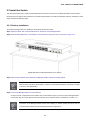
2.2 Install the Switch ........................................................................................................................................30
2.2.1 Desktop Installation .............................................................................................................................................30
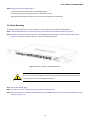
2.2.2 Rack Mounting.....................................................................................................................................................31
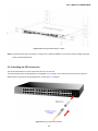
2.2.3 Installing the SFP transceiver ..............................................................................................................................32
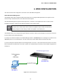
3. SWITCH MANAGEMENT .................................................................................................... 35
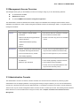
3.1 Requirements..............................................................................................................................................35
3.2 Management Access Overview .................................................................................................................36
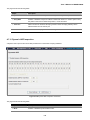
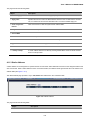
3.3 Administration Console .............................................................................................................................36
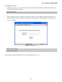
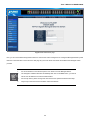
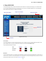
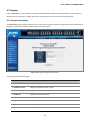
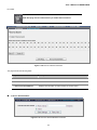
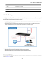
3.4 Web Management .......................................................................................................................................38
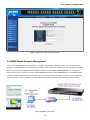
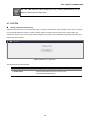
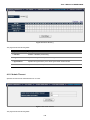
3.5 SNMP-Based Network Management.........................................................................................................39
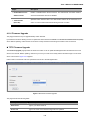
3.6 Protocols .....................................................................................................................................................40
3.6.1 Virtual Terminal Protocols ....................................................................................................................................40
3.6.2 SNMP Protocol ....................................................................................................................................................40
3.6.3 Management Architecture....................................................................................................................................40
4. WEB CONFIGURATION ...................................................................................................... 41
4.1 Main WEB PAGE .........................................................................................................................................44
4.2 System.........................................................................................................................................................46
3
User’s Manual of WGSW-48000
4.2.1 System Information..............................................................................................................................................46
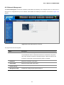
4.2.2 Network Management .........................................................................................................................................47
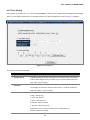
4.2.3 Time Setting.........................................................................................................................................................48
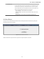
4.2.4 Green Ethernet ....................................................................................................................................................49
4.3 Port Management .......................................................................................................................................50
4.3.1 Port Configuration................................................................................................................................................50
4.3.2 LACP Property.....................................................................................................................................................52
4.3.3 LAG Group ..........................................................................................................................................................55
4.4 VLAN............................................................................................................................................................56
4.4.1 VLAN Overview ...................................................................................................................................................56
4.4.2 IEEE 802.1Q VLAN .............................................................................................................................................56
4.4.3 Create VLAN .......................................................................................................................................................61
4.4.4 VLAN Setting .......................................................................................................................................................62
4.4.5 VLAN Port............................................................................................................................................................64
4.4.6 GVRP ..................................................................................................................................................................65
4.5 Spanning Tree.............................................................................................................................................67
4.5.1 RSTP (Rapid Spanning Tree Protocol) ................................................................................................................73
4.5.2 RSTP Port ...........................................................................................................................................................74
4.5.3 MSTP...................................................................................................................................................................75
4.5.4 MSTP Port ...........................................................................................................................................................76
4.5.5 MSTP Instance ....................................................................................................................................................77
4.5.6 MSTP Interface....................................................................................................................................................78
4.6 Multicast ......................................................................................................................................................80
4.6.1 IGMP Snooping ...................................................................................................................................................80
4.6.2 Static Multicast.....................................................................................................................................................84
4.6.3 Static Multicast Table ...........................................................................................................................................84
4.6.4 IGMP ...................................................................................................................................................................86
4.7 Security .......................................................................................................................................................87
4.7.1 Port Security ........................................................................................................................................................87
4.7.2 ACL......................................................................................................................................................................88
4.7.3 802.1x..................................................................................................................................................................92
4.7.3.1 Understanding IEEE 802.1X Port-Based Authentication ...........................................................................93
4.7.3.2 802.1x Port Configuration..........................................................................................................................96
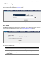
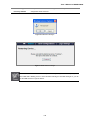
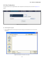
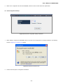
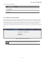
4.7.3.3 Windows Platform RADIUS Server Configuration .....................................................................................97
4.7.3.4 802.1X Client Configuration.......................................................................................................................99
4.7.4 RADIUS .............................................................................................................................................................101
4.7.5 TACACS+ ..........................................................................................................................................................102
4.7.6 Storm Control.....................................................................................................................................................104
4
User’s Manual of WGSW-48000
4.7.7 Management IP List...........................................................................................................................................105
4.7.8 Auto DoS ...........................................................................................................................................................106
4.7.9 SSH ...................................................................................................................................................................107
4.7.10 DHCP Snooping ..............................................................................................................................................108
4.7.11 Dynamic ARP Inspection .................................................................................................................................109
4.7.12 IP Source Guard .............................................................................................................................................. 110
4.7.13 HTTPS............................................................................................................................................................. 112
4.8 Quality of Service .....................................................................................................................................113
4.8.1 Understand QOS ............................................................................................................................................... 113
4.8.2 Queue Settings.................................................................................................................................................. 114
4.8.2 DSCP................................................................................................................................................................. 114
4.8.3 802.1P ............................................................................................................................................................... 117
4.8.4 Port-Based QoS ................................................................................................................................................ 119
4.8.5 Rate Control ......................................................................................................................................................120
4.8.6 DSCP Remark ...................................................................................................................................................121
4.9 SNMP .........................................................................................................................................................122
SNMP Overview .........................................................................................................................................................122
4.9.1 SNMP ................................................................................................................................................................123
4.9.2 Group Profile .....................................................................................................................................................124
4.9.3 User Profile........................................................................................................................................................125
4.9.4 Community Profile .............................................................................................................................................127
4.9.5 SNMP Trap Station ............................................................................................................................................128
4.10 LLDP ........................................................................................................................................................129
4.10.1 LLDP Settings..................................................................................................................................................129
4.10.2 LLDP Statistics.................................................................................................................................................130
4.10.3 Local Information .............................................................................................................................................131
4.10.4 Remote Information .........................................................................................................................................134
4.11 ADMIN ......................................................................................................................................................135
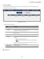
4.11.1 Admin Password ..............................................................................................................................................135
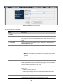
4.11.2 L2 Table ...........................................................................................................................................................136
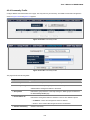
4.11.3 Static Address ..................................................................................................................................................137
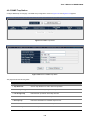
4.11.4 Port Mirroring ...................................................................................................................................................138
4.11.5 Admin Timeout .................................................................................................................................................139
4.11.6 Firmware Upgrade ...........................................................................................................................................140
4.11.7 Reboot .............................................................................................................................................................141
4.11.8 Save Configurations.........................................................................................................................................143
4.11.9 Logs Settings ...................................................................................................................................................146
4.11.10 Log Server .....................................................................................................................................................146
4.11.11 Memory Logs .................................................................................................................................................148
5
User’s Manual of WGSW-48000
4.11.12 Flash Logs .....................................................................................................................................................149
4.11.13 Ping Function .................................................................................................................................................150
4.11.14 Cable Diagnostic............................................................................................................................................150
4.11.15 DHCP Relay...................................................................................................................................................152
4.11.16 DHCP Option 82 ............................................................................................................................................152
4.11.17 Self Loop Detection........................................................................................................................................153
4.11.18 BOOTP Configure Download .........................................................................................................................154
4.12 Statistics..................................................................................................................................................155
4.12.1 802.1X Statistic................................................................................................................................................155
4.12.2 RMON Statistic ................................................................................................................................................156
4.12.3 RMON Event ...................................................................................................................................................158
4.12.4 RMON Event Log ............................................................................................................................................159
4.12.5 RMON Alarm ...................................................................................................................................................160
4.12.6 RMON History .................................................................................................................................................162
5. COMMAND LINE INTERFACE.......................................................................................... 164
5.1 Accessing the CLI ....................................................................................................................................164
Logon to the Console ..........................................................................................................................................164
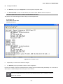
Configure IP address...........................................................................................................................................165
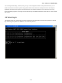
5.2 Telnet login................................................................................................................................................167
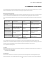
6. COMMAND LINE MODE ................................................................................................... 168
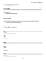
6.1 User Mode commands .............................................................................................................................169
help .....................................................................................................................................................................169
logout ..................................................................................................................................................................169
ping .....................................................................................................................................................................169
show port.............................................................................................................................................................170
show network ......................................................................................................................................................170
show system........................................................................................................................................................170
show port statistics ..............................................................................................................................................170
enable..................................................................................................................................................................171
Save ....................................................................................................................................................................171
6.2 Privileged Mode commands....................................................................................................................171
cable-diag port.....................................................................................................................................................171
6.2.1 Clear Command ................................................................................................................................................172
clear arl dynamic .................................................................................................................................................172
clear arl static mac...............................................................................................................................................172
clear config ..........................................................................................................................................................172
6
User’s Manual of WGSW-48000
clear counters......................................................................................................................................................172
clear igmpsnooping .............................................................................................................................................173
clear static-mcast ................................................................................................................................................173
clear pass ............................................................................................................................................................173
clear lacp .............................................................................................................................................................173
clear logs .............................................................................................................................................................173
clear vlan .............................................................................................................................................................174
configuration........................................................................................................................................................174
6.2.2 Copy Command.................................................................................................................................................174
copy nvram_config tftp ........................................................................................................................................174
copy system_image tftp.......................................................................................................................................174
copy tftp...............................................................................................................................................................175
exit.......................................................................................................................................................................175
help .....................................................................................................................................................................175
logout ..................................................................................................................................................................176
ping .....................................................................................................................................................................176
reload ..................................................................................................................................................................176
save.....................................................................................................................................................................176
6.2.3 Show Command ................................................................................................................................................177
show qos .............................................................................................................................................................177
show qos cos.......................................................................................................................................................177
show qos queue-settings.....................................................................................................................................177
show qos advanced.............................................................................................................................................177
show qos advanced mode...................................................................................................................................177
show qos advanced dscp ....................................................................................................................................177
show qos advanced ip-precedence .....................................................................................................................178
show qos port-based ...........................................................................................................................................178
show qos port-based port ....................................................................................................................................178
show qos port-based all.......................................................................................................................................178
show dot1x ..........................................................................................................................................................178
show dot1x config................................................................................................................................................179
show dot1x radius ...............................................................................................................................................179
show dot1x statistics............................................................................................................................................179
show igmpsnooping.............................................................................................................................................179
show igmpsnooping dynamic_router_port ...........................................................................................................179
show igmpsnooping groups .................................................................................................................................180
show igmpsnooping info ......................................................................................................................................180
show lag ..............................................................................................................................................................180
show lag lag-index...............................................................................................................................................180
show lag all..........................................................................................................................................................180
show lldp .............................................................................................................................................................181
7
User’s Manual of WGSW-48000
show lldp statistic.................................................................................................................................................181
show lldp local .....................................................................................................................................................181
show lldp msap....................................................................................................................................................181
show lldp msap-entry...........................................................................................................................................181
show logging .......................................................................................................................................................182
show logging memory-log....................................................................................................................................182
show logging flash-log .........................................................................................................................................182
show monitor .......................................................................................................................................................182
show network ......................................................................................................................................................182
show port.............................................................................................................................................................183
show port port-index ............................................................................................................................................183
show port all ........................................................................................................................................................183
show port-security ...............................................................................................................................................183
show port-security port ........................................................................................................................................183
show port-security all...........................................................................................................................................183
show rate-limit .....................................................................................................................................................184
show rate-limit port ..............................................................................................................................................184
show rate-limit all.................................................................................................................................................184
show running-config ............................................................................................................................................184
show snmp ..........................................................................................................................................................185
show snmp groups ..............................................................................................................................................185
show snmp users ................................................................................................................................................185
show snmp communities .....................................................................................................................................185
show snmp info ...................................................................................................................................................185
show sntp ............................................................................................................................................................186
show spanning-tree .............................................................................................................................................186
show spanning-tree interface ..............................................................................................................................186
show spanning-tree interface port .......................................................................................................................186
show spanning-tree interface all..........................................................................................................................186
show spanning-tree mst ......................................................................................................................................186
show spanning-tree mst detailed .........................................................................................................................187
show spanning-tree mst instance ........................................................................................................................187
show spanning-tree mst summary.......................................................................................................................187
show spanning-tree status...................................................................................................................................187
show storm-control ..............................................................................................................................................188
show sysinfo........................................................................................................................................................188
show switch .........................................................................................................................................................188
show switch admin-time ......................................................................................................................................188
show switch age-time ..........................................................................................................................................188
show switch mac-table ........................................................................................................................................189
show switch mac-table all....................................................................................................................................189
8
User’s Manual of WGSW-48000
show switch mac-table vlan.................................................................................................................................189
show switch mac-table port .................................................................................................................................189
show switch mcast-table......................................................................................................................................189
show switch mac .................................................................................................................................................190
show trapflags .....................................................................................................................................................190
show vlan ............................................................................................................................................................190
show vlan member ..............................................................................................................................................190
show vlan number ...............................................................................................................................................190
show rmon...........................................................................................................................................................191
show rmon event Index .......................................................................................................................................191
show rmon event .................................................................................................................................................191
Show rmon event log event _index .....................................................................................................................191
show rmon alarm index .......................................................................................................................................191
show rmon alarm.................................................................................................................................................192
show rmon history ...............................................................................................................................................192
show rmon history index......................................................................................................................................192
show rmon history ...............................................................................................................................................192
show rmon statistics ............................................................................................................................................193
show poe port-index ............................................................................................................................................193
show poe all ........................................................................................................................................................193
show poe system-status ......................................................................................................................................193
show tacplus........................................................................................................................................................194
show arp..............................................................................................................................................................194
show acl ..............................................................................................................................................................194
show dhcpsnooping config ..................................................................................................................................194
show dhcpsnooping port......................................................................................................................................194
show dhcpsnooping vlan .....................................................................................................................................195
show dhcpsnooping database .............................................................................................................................195
show dhcpsnooping database all.........................................................................................................................195
show dhcpsnooping database static....................................................................................................................195
show dhcpsnooping database dynamic...............................................................................................................195
show ipsrcgd config .............................................................................................................................................196
show ipsrcgd ports...............................................................................................................................................196
show ipsrcgd database........................................................................................................................................196
show https ...........................................................................................................................................................196
show loop_detect ................................................................................................................................................196
telnet ...................................................................................................................................................................197
6.3 Global Config mode commands .............................................................................................................198
exit.......................................................................................................................................................................198
6.3.1 VLAN Command................................................................................................................................................198
9
User’s Manual of WGSW-48000
vlan add...............................................................................................................................................................198
vlan add number..................................................................................................................................................198
vlan add range.....................................................................................................................................................198
vlan delete ...........................................................................................................................................................199
vlan port...............................................................................................................................................................199
vlan port all ..........................................................................................................................................................199
vlan port all port-configure ...................................................................................................................................199
vlan port all protected ..........................................................................................................................................199
vlan port all pvid ..................................................................................................................................................200
vlan port ports......................................................................................................................................................200
vlan port ports port-configure...............................................................................................................................200
vlan port ports protected......................................................................................................................................200
vlan port ports pvid ..............................................................................................................................................200
vlan lag ................................................................................................................................................................201
vlan lag vlan < vlan-id> exclude ..........................................................................................................................201
vlan lag vlan <vlan-ID> untagged ........................................................................................................................201
vlan lag vlan <vlan-ID> tagged ............................................................................................................................201
Bridge aging-time ................................................................................................................................................202
6.3.2 Link Aggregation Command ...............................................................................................................................202
lacp-syspri system-priority ...................................................................................................................................202
link-aggregation...................................................................................................................................................202
link-aggregation addport......................................................................................................................................202
link aggregation delport .......................................................................................................................................203
Link Aggregation delport all .................................................................................................................................203
link aggregation delport lag .................................................................................................................................203
6.3.3 LLDP Command ................................................................................................................................................203
lldp enable ...........................................................................................................................................................203
lldp disable ..........................................................................................................................................................203
lldp adv-interval ...................................................................................................................................................204
lldp fast-startcnt ...................................................................................................................................................204
lldp hold ...............................................................................................................................................................204
lldp notify-interval ................................................................................................................................................204
lldp reinit-delay ....................................................................................................................................................205
lldp tx-delay .........................................................................................................................................................205
lldp mgmt-addrtxport............................................................................................................................................205
6.3.4 Log Command ...................................................................................................................................................206
log .......................................................................................................................................................................206
log log-server.......................................................................................................................................................206
log log-server name <WORD>add ......................................................................................................................206
log log-server name <word> delete .....................................................................................................................206
log logging-target.................................................................................................................................................206
log logging-target memory...................................................................................................................................207
10
User’s Manual of WGSW-48000
log logging-target flash ........................................................................................................................................207
log logging-target console ...................................................................................................................................207
log logging-target server name <WORD>............................................................................................................207
radius-server ip....................................................................................................................................................208
static-address add ...............................................................................................................................................208
static-address delete ...........................................................................................................................................208
6.3.5 Mgmt Command ................................................................................................................................................209
mgmt-accesslist ipaddr........................................................................................................................................209
mgmt-accesslist enable .......................................................................................................................................209
mgmt-accesslist disable ......................................................................................................................................209
6.3.6 Monitor Command .............................................................................................................................................209
monitor enable.....................................................................................................................................................209
monitor disable ....................................................................................................................................................210
monitor des..........................................................................................................................................................210
monitor des <port-ID> probetype bidirection .......................................................................................................210
monitor des <port-ID> probetype ingress ............................................................................................................210
monitor des <port-ID> probetype egress ............................................................................................................. 211
6.3.7 dot1x Command ................................................................................................................................................ 211
dot1x enable........................................................................................................................................................ 211
dot1x disable ....................................................................................................................................................... 211
dot1x port-control ................................................................................................................................................ 211
dot1x port-control enable port..............................................................................................................................212
dot1x port-control disable port .............................................................................................................................212
6.3.8 network Command ............................................................................................................................................212
network mgmt-vlan ..............................................................................................................................................212
network parms .....................................................................................................................................................213
network protocol ..................................................................................................................................................213
network dhcp-relay ..............................................................................................................................................213
network dhcp-relay mode ....................................................................................................................................213
network dhcp-relay server ...................................................................................................................................213
network dhcp-relay vlan.......................................................................................................................................214
network dhcp-relay vlan <vlan-ID> add ...............................................................................................................214
network dhcp-relay vlan <vlan-ID> remove .........................................................................................................214
network sysinfo....................................................................................................................................................214
Network sysinfo sysname....................................................................................................................................214
network sysinfo syslocate....................................................................................................................................215
network sysinfo syscontact..................................................................................................................................215
network admin-timeout ........................................................................................................................................215
6.3.9 Port Command ..................................................................................................................................................215
port-all admin-mode ............................................................................................................................................215
port-all auto-negotiate .........................................................................................................................................216
11
User’s Manual of WGSW-48000
port-all flow-control ..............................................................................................................................................216
port-all portsec-lockmode ....................................................................................................................................216
port-all portsec-lockmode none ...........................................................................................................................216
port-all portsec-lockmode dynamic max-entries ..................................................................................................217
port-all rate-limit...................................................................................................................................................217
port-all rate-limit egress .......................................................................................................................................217
port-all rate-limit ingress ......................................................................................................................................217
port-all rmon-counter ...........................................................................................................................................217
port-all speed.......................................................................................................................................................218
port-all storm-control ...........................................................................................................................................218
port-all storm-control disable ...............................................................................................................................218
port-all storm-control broadcast...........................................................................................................................218
port-all storm-control broadcast-multicast............................................................................................................219
port-all storm-control broadcast-unknown ...........................................................................................................219
port-all storm-control all-cast ...............................................................................................................................219
6.3.10 QoS Command................................................................................................................................................219
qos qos-advanced ...............................................................................................................................................219
qos qos-advanced DSCP ....................................................................................................................................220
qos qos-advanced ip_precedence.......................................................................................................................220
qos qos-advanced none ......................................................................................................................................220
qos cos priority ....................................................................................................................................................220
qos dscp ..............................................................................................................................................................220
qos port-based port <WORD>status ...................................................................................................................221
qos scheduling ....................................................................................................................................................221
qos scheduling strict............................................................................................................................................221
qos scheduling wrr ..............................................................................................................................................221
qos ip-precedence...............................................................................................................................................222
qos wrr weight .....................................................................................................................................................222
qos dscp-remark acl_entry_name .......................................................................................................................222
6.3.11 Set Commang..................................................................................................................................................223
set IGMP .............................................................................................................................................................223
set igmp enable ...................................................................................................................................................223
set igmp disable ..................................................................................................................................................223
set igmp last-memberquery .................................................................................................................................223
set igmp last-membercount .................................................................................................................................223
set igmp query-interval ........................................................................................................................................224
set igmp query-resinterval ...................................................................................................................................224
set igmp robustness ............................................................................................................................................224
set igmp router-port ports ....................................................................................................................................224
set igmp-querier ..................................................................................................................................................225
set igmp-proxy.....................................................................................................................................................225
12
User’s Manual of WGSW-48000
set static-mcast ...................................................................................................................................................225
set static-mcast name <WORD> add vid.............................................................................................................225
set static-mcast name <WORD>delete ...............................................................................................................226
6.3.12 SNMP Command .............................................................................................................................................226
snmp notify ..........................................................................................................................................................226
snmp group add ..................................................................................................................................................226
snmp group delete...............................................................................................................................................227
snmp user add.....................................................................................................................................................227
snmp user delete.................................................................................................................................................227
snmp community add ..........................................................................................................................................228
snmp community delete.......................................................................................................................................228
snmp trapstation add <ip-addr> community <community name> type bootup trap-version.................................228
snmp trapstation add <ip-addr> community <community name> type linkchange trap-version ..........................229
snmp trapstation add <ip-addr> community <community name> type both trap-version.....................................229
snmp trapstation add <ip-addr> community <community name> type none trap-version....................................229
snmp trapstation delete .......................................................................................................................................229
6.3.13 SNTP Command..............................................................................................................................................230
sntp daylight ........................................................................................................................................................230
sntp localtime ......................................................................................................................................................230
sntp localtime enable...........................................................................................................................................230
sntp localtime localtime_date ..............................................................................................................................230
sntp server enable...............................................................................................................................................231
sntp server ipaddr................................................................................................................................................231
sntp server polling ...............................................................................................................................................231
sntp timezone ......................................................................................................................................................231
6.3.14 Spanning-tree Command.................................................................................................................................232
spanning-tree forceversion ..................................................................................................................................232
spanning-tree forceversion 8021s .......................................................................................................................232
spanning-tree forceversion 8021w ......................................................................................................................232
spanning-tree forceversion none .........................................................................................................................232
spanning-tree configuration .................................................................................................................................233
spanning-tree configuration name .......................................................................................................................233
spanning-tree configuration revision....................................................................................................................233
spanning-tree forward-time..................................................................................................................................233
spanning-tree max-age........................................................................................................................................233
spanning-tree max-hops......................................................................................................................................234
spanning-tree port ...............................................................................................................................................234
spanning-tree port all...........................................................................................................................................234
spanning-tree port cost........................................................................................................................................234
spanning-tree port priority....................................................................................................................................235
spanning-tree port edge ......................................................................................................................................235
13
User’s Manual of WGSW-48000
spanning-tree port force-p2plink ..........................................................................................................................235
spanning-tree port migration-check .....................................................................................................................235
spanning-tree port root-guard..............................................................................................................................236
spanning-tree priority...........................................................................................................................................236
spanning-tree mst................................................................................................................................................236
spanning-tree mst instance .................................................................................................................................236
spanning-tree mst instance add vlan ...................................................................................................................236
spanning-tree mst instance delete.......................................................................................................................237
spanning-tree mst vlan ........................................................................................................................................237
spanning-tree mst vlan <MST ID> <vlan list> add ...............................................................................................237
Spanning-Tree mst vlan <MST ID> <vlan list> delete..........................................................................................237
spanning-tree mst bridgepri.................................................................................................................................238
spanning-tree mst cost ........................................................................................................................................238
spanning-tree mst priority ....................................................................................................................................238
user password .....................................................................................................................................................238
Interface ..............................................................................................................................................................239
6.3.15 RMON Command ............................................................................................................................................239
rmon ....................................................................................................................................................................239
rmon event index.................................................................................................................................................239
rmon alarm index.................................................................................................................................................239
rmon del ..............................................................................................................................................................240
rmon del event index ...........................................................................................................................................240
rmon del alarm index ...........................................................................................................................................240
6.3.16 Access list Command ......................................................................................................................................240
access-list name <WORD> add priority...............................................................................................................240
access-list name <WORD> action.......................................................................................................................241
access-list name <WORD> action deny ..............................................................................................................241
access-list name <WORD> action permit............................................................................................................241
access-list name <WORD> clear ........................................................................................................................241
access-list name <WORD> clears SRC IP..........................................................................................................241
access-list name <WORD> clears DST IP ..........................................................................................................242
access-list name <WORD> clear L4port .............................................................................................................242
access-list name <WORD> clear L4port SRC port..............................................................................................242
access-list name <WORD> clear l4port DST port ...............................................................................................242
access-list name <WORD> clear packet-type .....................................................................................................242
access-list name <WORD> clear mac SA ...........................................................................................................242
access-list name <WORD> clear MAC DA..........................................................................................................243
access-list name <WORD> clear VID .................................................................................................................243
access-list name <WORD> clear ether-type .......................................................................................................243
access-list name <WORD> deletes.....................................................................................................................243
access-list name <WORD> {enable|disable}.......................................................................................................244
14
User’s Manual of WGSW-48000
access-list name <WORD> set ...........................................................................................................................244
access-list name <WORD> set priority................................................................................................................244
access-list name <WORD> set IP-mode .............................................................................................................244
access-list name <WORD> set IP-mode SRC IP. ...............................................................................................244
access-list name <WORD> set IP-mode DST IP ................................................................................................244
access-list name <WORD> set L4port ................................................................................................................245
access-list name <WORD> set l4port SRC-port SRE-port ..................................................................................245
access-list name <WORD> set l4port DST-port ..................................................................................................245
access-list name <WORD> set IP-mode packet-type .........................................................................................245
access-list name <WORD> set mac-mode..........................................................................................................246
access-list name <WORD> set mac-mode mac SA ............................................................................................246
access-list name <WORD> set mac-mode mac DA............................................................................................246
access-list name <WORD> set mac-mode ether-type ........................................................................................246
access-list name <name> set portlist ..................................................................................................................247
6.3.17 ARP Command ................................................................................................................................................247
arp dynamic.........................................................................................................................................................247
arp dynamic aging-time .......................................................................................................................................247
arp dynamic ports ................................................................................................................................................247
arp dynamic vlan .................................................................................................................................................248
arp static..............................................................................................................................................................248
6.3.18 Dos Command.................................................................................................................................................249
dos land...............................................................................................................................................................249
dos blat................................................................................................................................................................249
dos syn-fin ...........................................................................................................................................................249
dos ports..............................................................................................................................................................249
dos ports smurf....................................................................................................................................................249
dos ports ping-flooding ........................................................................................................................................250
dos ports synack-flooding....................................................................................................................................250
tacplus authen_type ............................................................................................................................................250
tacplus add server ...............................................................................................................................................251
tacplus del server ................................................................................................................................................251
green-eth .............................................................................................................................................................251
6.3.19 DHCP Snooping Command.............................................................................................................................252
dhcpsnooping enable ..........................................................................................................................................252
dhcpsnooping disable..........................................................................................................................................252
dhcpsnooping option82 .......................................................................................................................................252
dhcpsnooping verifymac......................................................................................................................................252
dhcpsnooping ports .............................................................................................................................................253
dhcpsnooping ports trust .....................................................................................................................................253
dhcpsnooping ports untrust .................................................................................................................................253
dhcpsnooping vlan ..............................................................................................................................................253
15
User’s Manual of WGSW-48000
dhcpsnooping vlan add........................................................................................................................................253
dhcpsnooping vlan remove..................................................................................................................................254
dhcpsnooping static.............................................................................................................................................254
dhcpsnooping static add ip ..................................................................................................................................254
dhcpsnooping static delete ip ..............................................................................................................................254
dhcpsnooping dyamic..........................................................................................................................................255
dhcpsnooping dynamic add ip .............................................................................................................................255
dhcpsnooping dynamic delete ip .........................................................................................................................255
6.3.20 Loop_detect Command ...................................................................................................................................256
Loop_detect enable.............................................................................................................................................256
loop_detect disable .............................................................................................................................................256
loop_detect recovertime ......................................................................................................................................256
loop detect trytorecover .......................................................................................................................................256
6.3.21 GVRP Command .............................................................................................................................................257
gvrp enable..........................................................................................................................................................257
gvrp disable .........................................................................................................................................................257
gvrp port_enable .................................................................................................................................................257
gvrp port_disable.................................................................................................................................................257
gvrp port_status...................................................................................................................................................258
https.....................................................................................................................................................................258
6.3.22 BOOTP Command...........................................................................................................................................258
bootp enable........................................................................................................................................................258
bootp disable .......................................................................................................................................................258
bootp renew.........................................................................................................................................................258
6.3.23 SSH Command................................................................................................................................................259
ssh enable ...........................................................................................................................................................259
ssh disable ..........................................................................................................................................................259
ssh changekey ....................................................................................................................................................259
6.3.24 IP Source Guard Command ............................................................................................................................260
ipsrcgd enable .....................................................................................................................................................260
ipsrcgd disable ....................................................................................................................................................260
ipsrcgd ports ........................................................................................................................................................260
ipsrcgd retry.........................................................................................................................................................260
ipsrcgd retry now .................................................................................................................................................260
ipsrcgd retry interval ............................................................................................................................................261
6.4 Interface Config mode commands .........................................................................................................261
exit.......................................................................................................................................................................261
6.4.1 dot1x Command ................................................................................................................................................261
Set 802.1x port control. .......................................................................................................................................261
lacp admin ...........................................................................................................................................................262
16
User’s Manual of WGSW-48000
lacp priority ..........................................................................................................................................................262
addport ................................................................................................................................................................262
delport .................................................................................................................................................................262
6.4.2 LLDP Command ................................................................................................................................................263
lldp state ..............................................................................................................................................................263
lldp notifications ...................................................................................................................................................263
lldp tlvs-tx ............................................................................................................................................................263
8021 set...............................................................................................................................................................264
8023 set...............................................................................................................................................................264
admin-mode ........................................................................................................................................................264
auto-negotiate .....................................................................................................................................................265
speed ..................................................................................................................................................................265
flow-control ..........................................................................................................................................................265
6.4.3 Port-security Command .....................................................................................................................................265
port-security.........................................................................................................................................................265
port-security lock-mode .......................................................................................................................................266
port-security lock-mode dynamic max-entries 24 ................................................................................................266
qos port-based priority.........................................................................................................................................266
Qos port-based status .........................................................................................................................................267
6.4.4 Rate-limit Command ..........................................................................................................................................267
rate-limit egress enable token bsize ....................................................................................................................267
rate-limit egress disable.......................................................................................................................................267
rate-limit ingress ..................................................................................................................................................267
storm-control .......................................................................................................................................................268
storm-control broadcast.......................................................................................................................................268
storm-control broadcast-multicast .......................................................................................................................268
storm-control broadcast-unknown .......................................................................................................................268
storm-control all-cast ...........................................................................................................................................269
rmon-counter .......................................................................................................................................................269
set igmp-router-port .............................................................................................................................................269
6.4.5 Spanning tree Command ...................................................................................................................................270
spanning-tree cost ...............................................................................................................................................270
spanning-tree edge .............................................................................................................................................270
spanning-tree force-p2plink .................................................................................................................................270
spanning-tree migration-check ............................................................................................................................270
spanning-tree mst cost ........................................................................................................................................271
spanning-tree mst priority ....................................................................................................................................271
spanning-tree participation ..................................................................................................................................271
spanning-tree priority...........................................................................................................................................272
6.4.6 VLAN Command................................................................................................................................................272
vlan participation exclude ....................................................................................................................................272
17
User’s Manual of WGSW-48000
vlan participation..................................................................................................................................................272
vlan protected......................................................................................................................................................273
vlan dropnq..........................................................................................................................................................273
vlan pvid ..............................................................................................................................................................273
Interface commands ............................................................................................................................................273
7. SWITCH OPERATION ....................................................................................................... 275
7.1 Address Table ...........................................................................................................................................275
7.2 Learning ....................................................................................................................................................275
7.3 Forwarding & Filtering .............................................................................................................................275
7.4 Store-and-Forward ...................................................................................................................................275
7.5 Auto-Negotiation ......................................................................................................................................275
8. TROUBLE SHOOTING...................................................................................................... 277
APPENDEX A ........................................................................................................................ 279
A.1 Switch's RJ-45 Pin Assignments ...........................................................................................................279
A.2 10/100Mbps, 10/100Base-TX ...................................................................................................................279
A.3 Available Modules....................................................................................................................................281
APPENDEX B : GLOSSARY................................................................................................. 282
18
User’s Manual of WGSW-48000
19
User’s Manual of WGSW-48000
1. INTRODUTION
The PLANET Layer 2 Managed Gigabit Switch series - WGSW-48000 is all multiple ports Gigabit Ethernet Switched with SFP
fiber optical connective ability and robust layer 2+ features; the description of these models as below:
Terms of “Managed Switch” means the Switches mentioned titled in the cover page of this User’s manual, i.e.WGSW-48000.
1.1 Packet Contents
Open the box of the Managed Switch and carefully unpack it. The box should contain the following items:
Check the contents of your package for following parts:
; The Managed Switch
x1
; User’s manual CD
x1
; Quick installation guide
x1
; 19” Rack mount accessory kit
x1
; Power cord
x1
; Rubber feet
X4
; RS-232 DB9 male Console cable
x1
If any of these are missing or damaged, please contact your dealer immediately, if possible, retain the carton including the
original packing material, and use them against to repack the product in case there is a need to return it to us for repair.
1.2 Product Description
High-Density / Cost-effective / Telecom class Gigabit solution for Enterprise backbone and Data Center
Networking
The PLANET WGSW-48000 is a Layer 2 / Layer 4 full managed Gigabit Switch that provides high density performance and is
rack mountable. With 96Gbps switching fabric, the WGSW-48000 can handle extremely large amounts of data in a secure
topology linking to an enterprise backbone or high capacity servers. The powerful QoS and Network Security features make
WGSW-48000 to perform effective data traffic control for both ISP and Enterprise VoIP, video streaming and multicast
applications.
High Performance
The WGSW-48000 provides 48 10/100/1000Mbps Gigabit Ethernet ports with 4 shared Gigabit SFP slots. It boasts a high
performance switch architecture that is capable of providing non-blocking switch fabric and wire-speed throughput as high as
96Gbps, which greatly simplifies the tasks of upgrading the LAN for catering to increasing bandwidth demands.
Robust Layer 2 Features
20
User’s Manual of WGSW-48000
The WGSW-48000 can be programmed for basic Switch management functions such as Port speed configuration, Port
aggregation, VLAN, Spanning Tree protocol, QoS, bandwidth control and IGMP Snooping. The WGSW-48000 provides 802.1Q
Tagged VLAN and GVRP protocol. The VLAN groups allowed on the WGSW-48000 will be maximally up to 255. By supporting
port aggregation, the WGSW-48000 allows the operation of a high-speed trunk combining multiple ports. It enables up to 14
groups of maximum 8-ports for trunking, and supports fail-over as well.
Excellent Traffic Control
PLANET WGSW-48000 is loaded with powerful traffic management and QoS features to enhance services offered by telecoms.
The functionality includes QoS features such as wire-speed Layer 4 traffic classifiers and bandwidth limiting that are particular
useful for multi-tenant unit, multi business unit, Telco, or Network Service Provide applications. It also empowers the enterprises
to take full advantages of the limited network resources and guarantees the best performance at VoIP and Video conferencing
transmission.
Efficient Management
For efficient management, the WGSW-48000 Managed Ethernet Switch is equipped with console, WEB and SNMP
management interfaces. With its built-in Web-based management interface, the PLANET WGSW-48000 offers an easy-to-use,
platform-independent management and configuration facility. The WGSW-48000 supports standard Simple Network
Management Protocol (SNMP) and can be managed via any standard-based management software. For text-based
management, WGSW-48000 can be accessed via Telnet and the console port. Moreover, the WGSW-48000 offers secure
remote management by supporting SSL and SSH connection which encrypts the packet content at each session.
Powerful Security
PLANET WGSW-48000 offers comprehensive Access Control List (ACL) for enforcing security to the edge. Its protection
mechanisms also comprise port-based 802.1x user and device authentication. The port-security is effective in limiting the
numbers of clients pass through, so that network administrators can now construct highly secured corporate networks with time
and effort considerably less than before.
Flexibility and Extension solution
The four mini-GBIC slots built in the WGSW-48000 are compatible with 1000Base-SX/LX and WDM SFP (Small Factor
Pluggable) fiber-optic modules. The distance can be extended from 550 meters (Multi-Mode fiber) up to above 10/50/70/120
kilometers (Single-Mode fiber or WDM fiber). It is well suited for applications within the enterprise data centers and distributions.
1.3 How to Use This Manual
This User Manual is structured as follows:
Section 2, INSTALLATION
The section explains the functions of the Switch and how to physically install the Managed Switch.
Section 3, SWITCH MANAGEMENT
21
User’s Manual of WGSW-48000
The section contains the information about the software function of the Managed Switch.
Section 4, WEB CONFIGURATION
The section explains how to manage the Managed Switch by Web interface.
Section 5, COMMAND LINE INTERFACE
The section describes how to use the Command Line interface (CLI).
Section 6, CLI CONFIGURATION
The section explains how to manage the Managed Switch by Command Line interface.
Section 7, SWITCH OPERATION
The chapter explains how to does the switch operation of the Managed Switch.
Section 8, TROUBSHOOTING
The chapter explains how to trouble shooting of the Managed Switch.
Appendix A
The section contains cable information of the Managed Switch.
22
User’s Manual of WGSW-48000
1.4 Product Features
¾
Physical Port
48-Port 10/100/1000Base-T Gigabit Ethernet RJ-45
4 mini-GBIC/SFP slots, shared with Port-23, Port-24, Port-47 and Port-48
RS-232 DB9 console interface for Switch basic management and setup
Layer 2 Features
Complies with the IEEE 802.3, IEEE 802.3u, IEEE 802.3ab, IEEE 802.3z Gigabit Ethernet standard
Supports Auto-negotiation and Half-Duplex / Full-Duplex modes for all 10Base-T/100Base-TX and 1000Base-T ports.
Auto-MDI/MDI-X detection on each RJ-45 port
Prevents packet loss Flow Control:
-
IEEE 802.3x FAUSE Frame flow control for Full-Duplex mode
-
Back-Pressure Flow Control in Half-Duplex mode
High performance Store and Forward architecture, broadcast storm control, runt/CRC filtering eliminates erroneous
packets to optimize the network bandwidth
8K MAC address table, automatic source address learning and ageing
4Mbit embedded memory for packet buffers
Support VLAN
C
-
IEEE 802.1Q Tag-based VLAN
-
GVRP for dynamic VLAN Management
-
Up to 255 VLANs groups, out of 4041 VLAN IDs
-
Private VLAN Edge (PVE) supported
-
Management VLAN
Support Link Aggregation
− up to 14 trunk groups
− up to 8 ports per trunk group with 1.6Gbps bandwidth (Full Duplex Mode)
− IEEE 802.3ad LACP (Link Aggregation Control Protocol)
− Cisco ether-channel (Static Trunk)
¾
Spanning Tree Protocol
-
STP, IEEE 802.1D (Classic Spanning Tree Protocol)
-
RSTP, IEEE 802.1w (Rapid Spanning Tree Protocol)
-
MSTP, IEEE 802.1s (Multiple Spanning Tree Protocol, spanning tree by VLAN)
Port Mirroring to monitor the incoming or outgoing traffic on a particular port ( many to many)
Quality of Service
4 priority queues on all switch ports
Traffic classification:
-
IEEE 802.1p CoS
-
IP TOS / DSCP / IP Precedence
-
Port-Based QoS
DSCP remarking based on ACL
Strict priority and Weighted Round Robin (WRR) CoS policies
Supports QoS and In/Out bandwidth control on each port
23
User’s Manual of WGSW-48000
Multicast
Support IGMP Snooping v1 and v2
IGMP Querier / IGMP Proxy / IGMP Immediately Leave support
Security
IEEE 802.1x Port-Based Authentication
Build-in RADIUS client to co-operate with the RADIUS servers
TACACS+ login users access authentication
IP-Based Access Control List (ACL)
MAC-Based Access Control List
Port Security
Supports DHCP Snooping
Supports Dynamic ARP Inspection
Supports IP Source Guard
Supports Auto Dos
Management
Switch Management Interface
-
Console / Telnet Command Line Interface
-
Web switch management
-
SNMP v1, v2c, and v3 switch management
-
SSH / SSL secure access
DHCP client for IP address assignment
Support DHCP relay function
Built-in Trivial File Transfer Protocol (TFTP) client
Firmware upload / download via TFTP or HTTP protocol
Configuration upload / download via TFTP or HTTP protocol
SNTP (Simple Network Time Protocol)
Message / event/ error / SNMP Trap logs
Logging to local file and syslog server
Four RMON groups 1, 2, 3, 9 (history, statistics, alarms, and events)
Supports Ping function
Cable Diagnostic technology provides the mechanism to detect and report potential cabling issues, such as cable
opens, cable shorts, and etc. on Copper Links
Link Layer Discovery Protocol (LLDP)
Management IP
Power Saving ability for Green networking
24
User’s Manual of WGSW-48000
1.5 Product Specification
WGSW-48000
T
T
Product
48-Port 10/100/1000Mbps with 4 Shared SFP Managed Gigabit Switch
Hardware Specification
Copper Ports
48 10/ 100/1000Base-T RJ-45 Auto-MDI/MDI-X ports
SFP / mini-GBIC slots
4 1000Base-SX/LX SFP interfaces, shared with Port-23, Port-24, Port-47 and Port-48
Switch Architecture
Store-and-forward
Switch Fabric
96Gbps / non-blocking
Switch throughput
71.4Mpps
Address Table
8K MAC address table with Auto learning function
Share data Buffer
4Mbits
C
Back pressure for Half-Duplex
Flow Control
IEEE 802.3x Pause Frame for Full-Duplex
Jumbo Frame
9K
LED
Power, Link/Act per port
< 10 sec: System reboot
Reset Button
> 10 sec: Factory Default
Dimension (W x D x H)
430 x 350x 44.5 mm, 1U height
Weight
3.5 KG
Power Consumption
74 Watt / 252.34 BTU (Maximum)
Power Requirement
AC 100~240V, 50/60Hz
Layer F function
T
Management Interface
Console, Telnet, SSH, Web Browser, SSL, SNMPv1, v2c and v3
Port disable/enable.
Port configuration
Auto-negotiation 10/100/1000Mbps full and half duplex mode selection.
Flow Control disable / enable.
Port Status
Display each port’s speed duplex mode, link status, Flow control status. Auto negotiation
status, trunk status.
IEEE 802.1Q Tag-based VLAN
VLAN
GVRP for VLAN Management
Up to 255 VLANs groups, out of 4041 VLAN IDs
Private VLAN Edge (PVE) supported
Bandwidth Control
Link Aggregation
QoS
Ingress Rate Limit
Egress Traffic Shaper
IEEE 802.3ad LACP / Static Trunk
Supports 14 groups of 8-Port trunk
Traffic classification based on 802.1p priority, DS/TOS field in IP Packet
25
User’s Manual of WGSW-48000
IGMP Snooping
Access Control List
IGMP (v1/v2) Snooping, IGMP Querier mode
IP-Based ACL / MAC-Based ACL
Up to 254 entries
RFC-1213 MIB-II
RFC-2863 Interface MIB
RFC-2665 EtherLike MIB
SNMP MIBs
RFC-1493 Bridge MIB
RFC-2674 Extended Bridge MIB
RFC-2819 RMON MIB (Group 1, 2, 3 and 9)
RFC-2737 Entity MIB
RFC-2618 RADIUS Client MIB
Standard Conformance
Regulation Compliance
FCC Part 15 Class A, CE
IEEE 802.3 10BASE-T
IEEE 802.3u 100BASE-TX / 100BASE-FX
IEEE 802.3z Gigabit SX/LX
IEEE 802.3ab Gigabit 1000T
IEEE 802.3x Flow Control and Back pressure
IEEE 802.3ad Port trunk with LACP
Standards Compliance
IEEE 802.1d Spanning tree protocol
IEEE 802.1w Rapid spanning tree protocol
IEEE 802.1s Multiple Spanning tree protocol
IEEE 802.1p Class of service
IEEE 802.1Q VLAN Tagging
IEEE 802.1x Port Authentication Network Control
IEEE 802.1ad LLDP
26
User’s Manual of WGSW-48000
2. INSTALLATION
This section describes the hardware features and installation of the Managed Switch on the desktop or rack mount. For easier
management and control of the Managed Switch, familiarize yourself with its display indicators, and ports. Front panel
illustrations in this chapter display the unit LED indicators. Before connecting any network device to the Managed Switch, please
read this chapter completely.
2.1 Hardware Description
2.1.1 Switch Front Panel
The unit front panel provides a simple interface monitoring the switch. Figure 2-1 shows the front panel of the Managed
Switches.
WGSW-48000 Front Panel
Figure 2-1 WGSW-48000 front panel.
■ Gigabit TP interface
10/100/1000Base-T Copper, RJ-45 Twist-Pair: Up to 100 meters.
■ Gigabit SFP slots
1000Base-SX/LX mini-GBIC slot, SFP (Small Factor Pluggable) transceiver module: From 550 meters (Multi-mode fiber),
up to 10/30/50/70/120 kilometers (Single-mode fiber).
■ Reset button
At the left of front panel, the reset button is designed for reboot the Managed Switch without turn off and on the power. The
following is the summary table of Reset button functions:
Reset Button Pressed and Released
Function
About 1~3 second
Reboot the Managed Switch
Reset the Managed Switch to Factory Default configuration.
The Managed Switch will then reboot and load the default
settings as below:
Until the PWR LED lit off
。
Default Password: admin
。
Default IP address: 192.168.0.100
。
Subnet mask: 255.255.255.0
。
Default Gateway: 192.168.0.254
27
User’s Manual of WGSW-48000
2.1.2 LED Indications
The front panel LEDs indicates instant status of port links, data activity, system operation and system power, helps monitor and
troubleshoot when needed.
WGSW-48000 LED indication
Figure 2-3 WGSW-48000 LED panel
■ System
LED
Color
Function
Lights to indicate that the Switch is powered on.
PWR
Green
Blink to indicate the System is running under booting procedure.
■ 10/100/1000Base-T interfaces
LED
Color
Function
Lights: To indicate the link through that port is successfully established with speed
1000Mbps
Blink: To indicate that the switch is actively sending or receiving data over that port.
1000
Green
LNK/ACT
Off:
If L10/100 NK/ACT LED light-> indicate that the port is operating at 10Mbps or
100Mbps
If LNK/ACT LED Off -> indicate that the port is link down
Lights: To indicate the link through that port is successfully established with speed
10Mbps or 100Mbps
10/100
Orange
Blink: To indicate that the switch is actively sending or receiving data over that port.
LNK/ACT
Off:
If 1000 LNK/ACT LED light-> indicate that the port is operating at 1000Mbps
If 1000 LNK/ACT LED Off -> indicate that the port is link down
28
User’s Manual of WGSW-48000
■ 1000Base-SX/LX SFP interfaces (Shared Port-23, Port-24, Port-47 and Port-48)
LED
Color
Function
Lights: To indicate the link through that SFP port is successfully established with
1000
speed 1000Mbps
Green
LNK
Off:
To indicate that the SFP port is link down
2.1.3 Switch Rear Panel
The rear panel of the Managed Switch indicates an AC inlet power socket, which accept input power from 100 to 240V AC,
50-60Hz. Figure 2-5 shows the rear panel of these Managed Switch.
WGSW-48000 Rear Panel
Figure 2-5 Rear panel of WGSW-48000
■ Console Port
The console port is a DB9, RS-232 male seria port connector. It is an interface for connecting a terminal directly. Through
the console port, it provides rich diagnostic information includes IP Address setting, factory reset, port management, link
status and system setting. Users can use the attached RS-232 cable in the package and connect to the console port on the
device. After the connection, users an run any terminal emulation program (Hyper Terminal, ProComm Plus, Telix, Winterm
and so on) to enter the statup screen of the device.
■ AC Power Receptacle
For compatibility with electric service in most areas of the world, the Managed Switch’s power supply automatically adjusts
to line power in the range 100-240VAC and 50/60 Hz.
Plug the female end of the power cord firmly into the receptalbe on the rear panel of the Managed Switch. Plug the other
end of the power cord into an electric service outlet then the power will be ready.
The device is a power-required device, it means, it will not work till it is powered. If your networks should
active all the time, please consider using UPS (Uninterrupted Power Supply) for your device. It will
Power Notice: prevent you from network data loss or network downtime.
In some area, installing a surge suppression device may also help to protect your Managed Switch from
being damaged by unregulated surge or current to the Switch or the power adapter.
29
User’s Manual of WGSW-48000
2.2 Install the Switch
This section describes how to install your Managed Switch and make connections to the Managed Switch. Please read the
following topics and perform the procedures in the order being presented. To install your Managed Switch on a desktop or shelf,
simply complete the following steps.
2.2.1 Desktop Installation
To install the Managed Switch on desktop or shelf, please follows these steps:
Step1: Attach the rubber feet to the recessed areas on the bottom of the Managed Switch.
Step2: Place the Managed Switch on the desktop or the shelf near an AC power source, as shown in Figure 2-10.
Figure 2-10 Place the Managed Switch on the desktop
Step3: Keep enough ventilation space between the Managed Switch and the surrounding objects.
When choosing a location, please keep in mind the environmental restrictions discussed in Chapter
1, Section 4, and Specification.
Step4: Connect the Managed Switch to network devices.
Connect one end of a standard network cable to the 10/100/1000 RJ-45 ports on the front of the Managed Switch
Connect the other end of the cable to the network devices such as printer servers, workstations or routers…etc.
Connection to the Managed Switch requires UTP Category 5 network cabling with RJ-45 tips. For
more information, please see the Cabling Specification in Appendix A.
30
User’s Manual of WGSW-48000
Step5: Supply power to the Managed Switch.
Connect one end of the power cable to the Managed Switch.
Connect the power plug of the power cable to a standard wall outlet.
When the Managed Switch receives power, the Power LED should remain solid Green.
2.2.2 Rack Mounting
To install the Managed Switch in a 19-inch standard rack, please follows the instructions described below.
Step1: Place the Managed Switch on a hard flat surface, with the front panel positioned towards the front side.
Step2: Attach the rack-mount bracket to each side of the Managed Switch with supplied screws attached to the package.
Figure 2-11 shows how to attach brackets to one side of the Managed Switch.
Figure 2-11 Attach brackets to the Managed Switch.
You must use the screws supplied with the mounting brackets. Damage caused to the parts by
using incorrect screws would invalidate the warranty.
Step3: Secure the brackets tightly.
Step4: Follow the same steps to attach the second bracket to the opposite side.
Step5: After the brackets are attached to the Managed Switch, use suitable screws to securely attach the brackets to the rack,
as shown in Figure 2-12.
31
User’s Manual of WGSW-48000
Figure 2-12 Mounting WGSW-48000 in a Rack
Step6: Proceeds with the steps 4 and steps 5 of session 2.2.1 Desktop Installation to connect the network cabling and supply
power to the Managed Switch.
2.2.3 Installing the SFP transceiver
The sections describe how to insert an SFP transceiver into an SFP slot.
The SFP transceivers are hot-pluggable and hot-swappable. You can plug-in and out the transceiver to/from any SFP port
without having to power down the Managed Switch. As the Figure 2-13 appears.
Figure 2-13 Plug-in the SFP transceiver
32
User’s Manual of WGSW-48000
Approved PLANET SFP Transceivers
PLANET Managed Switch supports both Single mode and Multi-mode SFP transceiver. The following list of approved PLANET
SFP transceivers is correct at the time of publication:
■ MGB-SX SFP (1000BASE-SX SFP transceiver / Multi-mode / 850nm / 220m~550m)
■ MGB-LX SFP (1000BASE-LX SFP transceiver / Single mode / 1310nm / 10km)
■ MGB-L30 SFP (1000BASE-LX SFP transceiver / Single mode / 1310nm / 30km)
■ MGB-L50 SFP (1000BASE-LX SFP transceiver / Single mode / 1310nm / 50km)
■ MGB-LA10 SFP (1000BASE-LX SFP transceiver / WDM Single mode / TX: 1310nm, RX: 1550nm/ 10km)
■ MGB-LB10 SFP (1000BASE-LX SFP transceiver / WDM Single mode / TX: 1550nm, RX: 1310nm / 10km)
It recommends using PLANET SFPs on the Managed Switch. If you insert a SFP transceiver that is
not supported, the Managed Switch will not recognize it.
Before connect the other Managed Switches, workstation or Media Converter.
1.
Make sure both side of the SFP transceiver are with the same media type, for example: 1000Base-SX to 1000Base-SX,
1000Bas-LX to 1000Base-LX.
2.
Check the fiber-optic cable type match the SFP transceiver model.
¾
To connect to 1000Base-SX SFP transceiver, use the Multi-mode fiber cable- with one side must be male duplex LC
connector type.
¾
To connect to 1000Base-LX SFP transceiver, use the Single-mode fiber cable-with one side must be male duplex LC
connector type.
Connect the fiber cable
1.
Attach the duplex LC connector on the network cable into the SFP transceiver.
2.
Connect the other end of the cable to a device – switches with SFP installed, fiber NIC on a workstation or a Media
Converter..
3.
Check the LNK/ACT LED of the SFP slot on the front of the Managed Switch. Ensure that the SFP transceiver is operating
correctly.
4.
Check the Link mode of the SFP port if the link failed. Co works with some fiber-NICs or Media Converters, set the Link
mode to “1000 Force” is needed.
Remove the transceiver module
1.
Make sure there is no network activity by consult or check with the network administrator. Or through the management
interface of the switch/converter (if available) to disable the port in advance.
2.
Remove the Fiber Optic Cable gently.
3.
Turn the handle of the MGB module to horizontal.
4.
Pull out the module gently through the handle.
33
User’s Manual of WGSW-48000
Figure 2-14 Pull out the SFP transceiver
Never pull out the module without pull the handle or the push bolts on the module. Direct pull
out the module with violent could damage the module and SFP module slot of the Managed
Switch.
34
User’s Manual of WGSW-48000
3. SWITCH MANAGEMENT
This chapter explains the methods that you can use to configure management access to the Managed Switch. It describes the
types of management applications and the communication and management protocols that deliver data between your
management device (work-station or personal computer) and the system. It also contains information about port connection
options.
This chapter covers the following topics:
Requirements
Management Access Overview
Administration Console Access
Web Management Access
SNMP Access
Standards, Protocols, and Related Reading
3.1 Requirements
Workstations of subscribers running Windows 98/ME, NT4.0, 2000/XP, MAC OS9 or later, Linux, UNIX or other
platform compatible with TCP/IP protocols.
Workstation installed with Ethernet NIC (Network Interface Card)
Serial Port connect (Terminal)
• Above PC with COM Port (DB-9 / RS-232) or USB-to-RS-232 converter
Ethernet Port connect
• Network cables - Use standard network (UTP) cables with RJ45 connectors.
Above Workstation installed with WEB Browser and JAVA runtime environment Plug-in
It is recommended to use Internet Explore 6.0 or above to access Managed Switch.
35
User’s Manual of WGSW-48000
3.2 Management Access Overview
The Managed Switch gives you the flexibility to access and manage it using any or all of the following methods:
An administration console
Web browser interface
An external SNMP-based network management application
The administration console and Web browser interface support are embedded in the Managed Switch software and are
available for immediate use. Each of these management methods has their own advantages. Table 3-1 compares the three
management methods.
Method
Console
Advantages
Disadvantages
• No IP address or subnet needed
• Must be near switch or use dial-up connection
• Text-based
• Not convenient for remote users
• Telnet functionality and HyperTerminal
• Modem connection may prove to be unreliable
built into Windows
or slow
95/98/NT/2000/ME/XP operating
systems
• Secure
Web Browser
• Ideal for configuring the switch remotely
• Compatible with all popular browsers
• Security can be compromised (hackers need
only know the IP address and subnet mask)
• Can be accessed from any location
• May encounter lag times on poor connections
• Most visually appealing
SNMP Agent
• Communicates with switch functions at
• Requires SNMP manager software
• Least visually appealing of all three methods
the MIB level
• Based on open standards
• Some settings require calculations
• Security can be compromised (hackers need
only know the community name)
Table 3-1 Management Methods Comparison
3.3 Administration Console
The administration console is an internal, character-oriented, and command line user interface for performing system
administration such as displaying statistics or changing option settings. Using this method, you can view the administration
console from a terminal, personal computer, Apple Macintosh, or workstation connected to the switch's console (serial) port.
There are two ways to use this management method: via direct access or modem port access. The following sections describe
these methods. For more information about using the console, refer to Chapter 5 Command Line Interface Console
Management.
36
User’s Manual of WGSW-48000
Figure 3-1 Console management
Direct Access
Direct access to the administration console is achieved by directly connecting a terminal or a PC equipped with a
terminal-emulation program (such as HyperTerminal) to the Managed Switch console (serial) port.
When using this management method, a straight DB9 RS-232 cable is required to connect the switch to the PC. After
making this connection, configure the terminal-emulation program to use the following parameters:
The default parameters are:
38400 bps
8 data bits
No parity
1 stop bit
Figure 3-2 Terminal parameter settings
37
User’s Manual of WGSW-48000
You can change these settings, if desired, after you log on. This management method is often preferred because you can
remain connected and monitor the system during system reboots. Also, certain error messages are sent to the serial port,
regardless of the interface through which the associated action was initiated. A Macintosh or PC attachment can use any
terminal-emulation program for connecting to the terminal serial port. A workstation attachment under UNIX can use an emulator
such as TIP.
3.4 Web Management
The Managed Switch offers management features that allow users to manage the Managed Switch from anywhere on the
network through a standard browser such as Microsoft Internet Explorer. After you set up your IP address for the switch, you can
access the Managed Switch's Web interface applications directly in your Web browser by entering the IP address of the
Managed Switch.
Figure 3-3 Web management
You can then use your Web browser to list and manage the Managed Switch configuration parameters from one central location,
just as if you were directly connected to the Managed Switch's console port. Web Management requires either Microsoft
Internet Explorer 6.0 or later, Safari or Mozilla Firefox 1.5 or later.
38
User’s Manual of WGSW-48000
Figure 3-4 Web main screen of Managed Switch
3.5 SNMP-Based Network Management
You can use an external SNMP-based application to configure and manage the Managed Switch, such as SNMPc Network
Manager, HP Openview Network Node Management (NNM) or What’s Up Gold. This management method requires the SNMP
agent on the switch and the SNMP Network Management Station to use the same community string. This management
method, in fact, uses two community strings: the get community string and the set community string. If the SNMP Net-work
management Station only knows the set community string, it can read and write to the MIBs. However, if it only knows the get
community string, it can only read MIBs. The default gets and sets community strings for the Managed Switch are public.
Figure 3-4 SNMP management
39
User’s Manual of WGSW-48000
3.6 Protocols
The Managed Switch supports the following protocols:
Virtual terminal protocols, such as Telnet
Simple Network Management Protocol (SNMP)
3.6.1 Virtual Terminal Protocols
A virtual terminal protocol is a software program, such as Telnet, that allows you to establish a management session from a
Macintosh, a PC, or a UNIX workstation. Because Telnet runs over TCP/IP, you must have at least one IP address configured on
the Managed Switch before you can establish access to it with a virtual terminal protocol.
Terminal emulation differs from a virtual terminal protocol in that you must connect a terminal directly
to the console (serial) port.
To access the Managed Switch through a Telnet session:
1.
Be Sure of the Managed Switch is configured with an IP address and the Managed Switch is reachable from a PC.
2.
Start the Telnet program on a PC and connect to the Managed Switch.
The management interface is exactly the same with RS-232 console management.
3.6.2 SNMP Protocol
Simple Network Management Protocol (SNMP) is the standard management protocol for multi-vendor IP networks. SNMP
supports transaction-based queries that allow the protocol to format messages and to transmit information between reporting
devices and data-collection programs. SNMP runs on top of the User Datagram Protocol (UDP), offering a connectionless-mode
service.
3.6.3 Management Architecture
All of the management application modules use the same Messaging Application Programming Interface (MAPI). By unifying
management methods with a single MAPI, configuration parameters set using one method (console port, for example) are
immediately displayable by the other management methods (for example, SNMP agent of Web browser).
The management architecture of the switch adheres to the IEEE open standard. This compliance assures customers that the
Managed Switch is compatible with, and will interoperate with other solutions that adhere to the same open standard.
40
User’s Manual of WGSW-48000
4. WEB CONFIGURATION
This section introduces the configuration and functions of the Web-Based management.
About Web-based Management
The Managed Switch offers management features that allow users to manage the Managed Switch from anywhere on the
network through a standard browser such as Microsoft Internet Explorer.
The Web-Based Management supports Internet Explorer 6.0. It is based on Java Applets with an aim to reduce network
bandwidth consumption, enhance access speed and present an easy viewing screen.
By default, IE6.0 or later version does not allow Java Applets to open sockets. The user has to
explicitly modify the browser setting to enable Java Applets to use network ports.
The Managed Switch can be configured through an Ethernet connection, make sure the manager PC must be set on same the
IP subnet address with the Managed Switch.
For example, the default IP address of the WGSW Managed Switch is 192.168.0.100, then the manager PC should be set at
192.168.0.x (where x is a number between 1 and 254, except 100), and the default subnet mask is 255.255.255.0.
If you have changed the default IP address of the Managed Switch to 192.168.1.1 with subnet mask 255.255.255.0 via console,
then the manager PC should be set at 192.168.1.x (where x is a number between 2 and 254) to do the relative configuration on
manager PC.
WGSW Managed Switch
PC/Workstation
With
IE Browser
IP Address:
192.168.0.100
RJ-45/UTP Cable
IP Address:
192.168.0.x
Figure 4-1-1 Web Management
41
User’s Manual of WGSW-48000
1.
Logging on the switch
Use Internet Explorer 6.0 or above Web browser. Enter the factory-default IP address to access the Web interface. The
factory-default IP Address as following:
http://192.168.0.100
2.
When the following login screen appears, please enter the default username "admin" with password “admin” (or the
username/password you have changed via console) to login the main screen of Managed Switch. The login screen in
Figure 4-1-2 appears.
Figure 4-1-2 Login screen
Default User name: admin
Default Password: admin
After entering the username and password, the main screen appears as Figure 4-1-3.
42
User’s Manual of WGSW-48000
Figure 4-1-3 Default main page
Now, you can use the Web management interface to continue the switch management or manage the Managed Switch by Web
interface. The Switch Menu on the left of the web page let you access all the commands and statistics the Managed Switch
provides.
1.
It is recommended to use Internet Explore 6.0 or above to access Managed Switch.
2.
The changed IP address take effect immediately after click on the Save button, you need to
use the new IP address to access the Web interface.
3.
For security reason, please change and memorize the new password after this first setup.
4.
Only accept command in lowercase letter under web interface.
43
User’s Manual of WGSW-48000
4.1 Main WEB PAGE
The WGSW Managed Switch provides a Web-based browser interface for configuring and managing it. This interface allows
you to access the Managed Switch using the Web browser of your choice. This chapter describes how to use the Managed
Switch’s Web browser interface to configure and manage it.
Copper Port Link Status
Main Functions Menu
SFP Port Link Status
Main Screen
Figure 4-1-4 Main Page
Help Button
Panel Display
The web agent displays an image of the Managed Switch’s ports. The Mode can be set to display different information for the
ports, including Link up or Link down. Clicking on the image of a port opens the Port Statistics page.
The port states are illustrated as follows:
State
Disabled
Down
Link
RJ-45 Ports
SFP Ports
607H
608H
609H
Main Menu
Using the onboard web agent, you can define system parameters, manage and control the Managed Switch, and all its ports, or
monitor network conditions. Via the Web-Management, the administrator can setup the Managed Switch by select the functions
those listed in the Main Function. The screen in Figure 4-1-5 appears.
44
User’s Manual of WGSW-48000
Figure 4-1-5 WGSW Managed Switch Main Funcrions Menu
45
User’s Manual of WGSW-48000
4.2 System
Use the System menu items to display and configure basic administrative details of the Managed Switch. Under System the
following topics are provided to configure and view the system information: This section has the following items:
4.2.1 System Information
The System Info page provides information for the current device information. System Info page helps a switch administrator to
identify the hardware MAC address, software version and system uptime.
Figure 4-2-1 System Information Screenshot
The page includes the following fields:
Object
Description
• Device name
Displays the switch model name.
• Hardware Version
Displays the hardware version number.
• Firmware Version
Displays the switch firmware version.
• Build Date
Displays the firmware built date.
• MAC Address
Displays the MAC address of the switch.
• System Name
Displays the user-defined system name.
• System Location
Displays the user-defined system location.
• System Contact
Displays the user-defined system contact person.
46
User’s Manual of WGSW-48000
4.2.2 Network Management
The Network Managment includes the IP Address, Subnet Mask and Gateway. The Configured column is used to view or
change the IP configuration.Fill up the IP Address, Subnet Mask and Gateway for the device. The screen in Figure 4-2-2
appears.
Figure 4-2-2 Network Management screenshot
The page includes the following fields:
Object
Description
• IP Address Mode
Retrieves the IP address using DHCP or Static.
The possible field values are DHCP that retrieves the IP addresses using DHCP
client; Static indicates IP address is statically assigned. If Static was selected, the
IP Address, Subnet Mask and Default Gateway fields are available.
• IP Address
Defines the IP address of the system.
• Subnet Mask
Defines the subnet mask of the system.
• Default Gateway
Defines the default gateway IP address of the system.
• Management VLAN
Indicates the VLAN group that system belongs to.
47
User’s Manual of WGSW-48000
4.2.3 Time Setting
In the System sub-function menu, you can see the Time Setting, by which you can configure the time settings for the Managed
Switch. You can specify SNTP Servers and set GMT Timezone. The SNTP Configuration screen in Figure 4-2-3 appears.
Figure 4-2-3 Time Settings
The page includes the following fields:
Object
Description
• Daylight Saving
Indicates the Daylight Savings Time (DST) on the device based on the devices
location. When daylight saving is enabled, one hour will be added to time zone
offset value. (Only for SNTP)
• Time Zone
Specifies the difference between Greenwich Mean Time (GMT) and local time.
For example, the Time Zone Offset for Paris is GMT +1, while the local time in
New York is GMT -5. (Only for SNTP)
• Use Local Time
M: Month - Sets the month.
D: Day - Sets the day.
Y: Year - Sets the year.
H: Hours - Sets the hours.
M: Minutes - Sets the minutes.
S: Seconds - Sets the seconds.
Use Browser Time - The device system time is configured by your
Desktop/Laptop's time setting.
48
User’s Manual of WGSW-48000
• Use SNTP Server
The device supports the Simple Network Time Protocol (SNTP). SNTP assures
accurate network device clock time synchronization up to the millisecond. Time
synchronization is performed by a network SNTP server. The device operates
only as an SNTP client, and cannot provide time services to other systems. The
device can poll the following server types for the server time:
Server IP Address - Sets the SNTP server's IP address.
Update Time Now - Synchronizes current device time with the SNTP server
right away.
Polling Interval - Sets the interval at which SNTP client polls for time.
4.2.4 Green Ethernet
This page is used to enable/disable green Ethernet function. Enable green Ethernet mode will reduce system power
consumption when the link is not present.
Figure 4-2-4 Green Ethernet screenshot
Enable mode will reduce chip power when the signal from the copper link partner is not present.
49
User’s Manual of WGSW-48000
4.3 Port Management
Use the Port Menu to display or configure the Managed Switch's ports. This section has the following items:
-
Port Configuration
-
LACP Property
-
LAG Group
4.3.1 Port Configuration
This page displays current port configurations. Ports can also be configured here.
The port settings relate to the currently selected stack unit, as reflected by the page header.
Figure 4-3-1 Port Configuration screenshot
The page includes the following fields:
Object
Description
• Port Number
Indicates the port numbers in the system.
Click on the port index will enter port configuration page.
• Admin Mode
Configure the administrative mode of the port. Sets to Disable will force the port
to link down status.
• Auto Negotiation
Configure the port auto-negotiation capability. When auto-negotiation is enabled,
the port negotiates with the link partner and works out speed and duplex
operation. When auto-negotiation is disabled, port speed and duplex operation is
programmable by the user.
50
User’s Manual of WGSW-48000
• Speed Duplex
Indicates the speed and duplex mode if the port is linkup.
• Flow Control
Indicates the state of flow control if the port is linkup.
• LAG Group
Indicates the LAG group if the port is a LAG port.
• Link Status
Displays the link status of the port.
Figure 4-3-2 Port Detail Configuration
51
User’s Manual of WGSW-48000
4.3.2 LACP Property
Link Aggregation Control Protocol (LACP) is part of an IEEE specification (802.3ad) that allows several physical ports to be
bundled together to form a single logical channel. Link Aggregation allows one or more links to be aggregated together to form a
Link Aggregation Group, such that a MAC Client can treat the Link Aggregation Group as if it were a single link. Link aggregation
can be used on 10Mbps, 100Mbps, or 1000Mbps ethernet full duplex ports. Example: A network administrator could combine a
group of four 1000Mbps ports into a logical link that will function as a single 4000Mbps port (The actual throughput however will
be less than the sum total of the links).
Figure 4-3-3Link Aggregation
The Link Aggregation Control Protocol (LACP) provides a standardized means for exchanging information between Partner
Systems that require high speed redundant links. Link aggregation lets you group up to eight consecutive ports into a single
dedicated connection. This feature can expand bandwidth to a device on the network. LACP operation requires full-duplex mode,
more detail information refer to the IEEE 802.3ad standard.
Port link aggregations can be used to increase the bandwidth of a network connection or to ensure fault recovery. Link
aggregation lets you group up to 4 consecutive ports into a single dedicated connection between any two the Switch or other
Layer 2 switches. However, before making any physical connections between devices, use the Link aggregation Configuration
menu to specify the link aggregation on the devices at both ends. When using a port link aggregation, note that:
52
User’s Manual of WGSW-48000
• The ports used in a link aggregation must all be of the same media type (RJ-45, 100 Mbps fiber).
• The ports that can be assigned to the same link aggregation have certain other restrictions (see below).
• Ports can only be assigned to one link aggregation.
• The ports at both ends of a connection must be configured as link aggregation ports.
• None of the ports in a link aggregation can be configured as a mirror source port or a mirror target port.
• All of the ports in a link aggregation have to be treated as a whole when moved from/to, added or deleted from a VLAN.
• The Spanning Tree Protocol will treat all the ports in a link aggregation as a whole.
• Enable the link aggregation prior to connecting any cable between the switches to avoid creating a data loop.
• Disconnect all link aggregation port cables or disable the link aggregation ports before removing a port link aggregation to
avoid creating a data loop.
It allows a maximum of 8 ports to be aggregated at the same time. The Managed Switch support Gigabit Ethernet ports (up to
14groups). If the group is defined as a LACP static link aggregationing group, then any extra ports selected are placed in a
standby mode for redundancy if one of the other ports fails. If the group is defined as a local static link aggregationing group,
then the number of ports must be the same as the group member ports.
The aggregation code ensures that frames belonging to the same frame flow (for example, a TCP connection) are always
forwarded on the same link aggregation member port. Reording of frames within a flow is therefore not possible. The
aggregation code is based on the following information:
• Source MAC
• Destination MAC
• Source and destination IPv4 address.
• Source and destination TCP/UDP ports for IPv4 packets
Normally, all 5 contributions to the aggregation code should be enabled to obtain the best traffic distribution among the link
aggregation member ports. Each link aggregation may consist of up to 8 member ports. Any quantity of link aggregation s may
be configured for the device (only limited by the quantity of ports on the device.) To configure a proper traffic distribution, the
ports within a link aggregation must use the same link speed.
Link Aggregation Port Configuration
Link Aggregation Control Protocol (LACP) - LACP LAG negotiate Aggregated Port links with other LACP ports located on a
different device. LACP allows switches connected to each other to discover automatically whether any ports are member of the
same LAG.
This page allows the user to inspect the current LACP port configurations, and possibly change them as well. The LACP port
settings relate to the currently selected stack unit, as reflected by the page header. The LACP Port Configuration screen in
Figure 4-3-4 appears.
53
User’s Manual of WGSW-48000
Figure 4-3-4 LACP Property
The page includes the following fields:
Object
Description
• LACP System Priority
Specifies the actor device's link aggregation priority relative to the devices at the
other ends of the links on which link aggregation is enabled. A higher value
indicates a lower priority.
• Port Number
Display the port number. Click on the index number will enter port LACP
properties configuration screen.
• Priority
Indicates actor port priority. The port priority determines the active and standby
links. When a group of ports is negotiating with a group of ports on another
device to establish a trunk group, the port with the highest priority becomes the
default active port. The other ports (with lower priorities) become standby ports in
the trunk group.
• Admin Key
Indicates actor administration key for the port. The LACP administration key must
be set to the same value for ports that belong to the same LAG.
• LAG Group
Indicates the LAG group ID if the port is the member of this LAG group.
• Status
Summarizes the current LACP status for this port.
• LACP Port Priority
Specifies actor port priority. The port priority determines the active and standby
links. When a group of ports is negotiating with a group of ports on another
device to establish a LAG group, the port with the highest priority becomes the
default active port. The other ports (with lower priorities) become standby ports in
the LAG group. You can specify a priority from 0 to 65535.
54
User’s Manual of WGSW-48000
All information listed here is for reference only. Please refer to IEEE 802.3ad for details.
4.3.3 LAG Group
Link Aggregated Groups optimize port usage by linking a group of ports together to form a single aggregated group. Link
aggregated groups multiply the bandwidth between the devices, increase port flexibility, and provide link redundancy.
Figure 4-3-4 LAG Group
The page includes the following fields:
Object
Description
• LAG Group
Displays the LAG groups.
• Port Member
Displays the ports that are members of this LAG.
• Link Status
Displays the link status.
• Speed /Duplex
Display the connection speed and duplex.
55
User’s Manual of WGSW-48000
4.4 VLAN
4.4.1 VLAN Overview
A Virtual Local Area Network (VLAN) is a network topology configured according to a logical scheme rather than the physical
layout. VLAN can be used to combine any collection of LAN segments into an autonomous user group that appears as a single
LAN. VLAN also logically segment the network into different broadcast domains so that packets are forwarded only between
ports within the VLAN. Typically, a VLAN corresponds to a particular subnet, although not necessarily.
VLAN can enhance performance by conserving bandwidth, and improve security by limiting traffic to specific domains.
A VLAN is a collection of end nodes grouped by logic instead of physical location. End nodes that frequently communicate with
each other are assigned to the same VLAN, regardless of where they are physically on the network. Logically, a VLAN can be
equated to a broadcast domain, because broadcast packets are forwarded to only members of the VLAN on which the
broadcast was initiated.
1.
No matter what basis is used to uniquely identify end nodes and assign these nodes VLAN
membership, packets cannot cross VLAN without a network device performing a routing
function between the VLAN.
2.
The Managed Switch supports IEEE 802.1Q VLAN. The port untagging function can be used
to remove the 802.1 tag from packet headers to maintain compatibility with devices that are
tag-unaware.
3.
The Managed Switch's default is to assign all ports to a single 802.1Q VLAN named
DEFAULT_VLAN. As new VLAN is created, the member ports assigned to the new VLAN will
be removed from the DEFAULT_ VLAN port member list. The DEFAULT_VLAN has a VID = 1.
This section has the following items:
IEEE 802.1Q VLAN
Enable IEEE 802.1Q Tag based VLAN group
4.4.2 IEEE 802.1Q VLAN
In large networks, routers are used to isolate broadcast traffic for each subnet into separate domains. This Managed Switch
provides a similar service at Layer 2 by using VLANs to organize any group of network nodes into separate broadcast domains.
VLANs confine broadcast traffic to the originating group, and can eliminate broadcast storms in large networks. This also
provides a more secure and cleaner network environment.
An IEEE 802.1Q VLAN is a group of ports that can be located anywhere in the network, but communicate as though they belong
to the same physical segment.
VLANs help to simplify network management by allowing you to move devices to a new VLAN without having to change any
56
User’s Manual of WGSW-48000
physical connections. VLANs can be easily organized to reflect departmental groups (such as Marketing or R&D), usage groups
(such as e-mail), or multicast groups (used for multimedia applications such as videoconferencing).
VLANs provide greater network efficiency by reducing broadcast traffic, and allow you to make network changes without having
to update IP addresses or IP subnets. VLANs inherently provide a high level of network security since traffic must pass through
a configured Layer 3 link to reach a different VLAN.
This Managed Switch supports the following VLAN features:
Up to 255 VLANs based on the IEEE 802.1Q standard
Distributed VLAN learning across multiple switches using explicit or implicit tagging and GVRP protocol
Port overlapping, allowing a port to participate in multiple VLANs
End stations can belong to multiple VLANs
Passing traffic between VLAN-aware and VLAN-unaware devices
Priority tagging
1.
The Managed Switch allows 4k user-manageable VLANs.
■ IEEE 802.1Q Standard
IEEE 802.1Q (tagged) VLAN are implemented on the Switch. 802.1Q VLAN require tagging, which enables them to span the
entire network (assuming all switches on the network are IEEE 802.1Q-compliant).
VLAN allow a network to be segmented in order to reduce the size of broadcast domains. All packets entering a VLAN will only
be forwarded to the stations (over IEEE 802.1Q enabled switches) that are members of that VLAN, and this includes broadcast,
multicast and unicast packets from unknown sources.
VLAN can also provide a level of security to your network. IEEE 802.1Q VLAN will only deliver packets between stations that are
members of the VLAN. Any port can be configured as either tagging or untagging. The untagging feature of IEEE 802.1Q VLAN
allows VLAN to work with legacy switches that don't recognize VLAN tags in packet headers. The tagging feature allows VLAN
to span multiple 802.1Q-compliant switches through a single physical connection and allows Spanning Tree to be enabled on all
ports and work normally.
Any port can be configured as either tagging or untagging. The untagging feature of IEEE 802.1Q VLAN allow VLAN to work
with legacy switches that don’t recognize VLAN tags in packet headers. The tagging feature allows VLAN to span multiple
802.1Q-compliant switches through a single physical connection and allows Spanning Tree to be enabled on all ports and work
normally.
Some relevant terms:
-
Tagging - The act of putting 802.1Q VLAN information into the header of a packet.
-
Untagging - The act of stripping 802.1Q VLAN information out of the packet header.
57
User’s Manual of WGSW-48000
■ 802.1Q VLAN Tags
The figure below shows the 802.1Q VLAN tag. There are four additional octets inserted after the source MAC address. Their
presence is indicated by a value of 0x8100 in the Ether Type field. When a packet's Ether Type field is equal to 0x8100, the
packet carries the IEEE 802.1Q/802.1p tag. The tag is contained in the following two octets and consists of 3 bits of user priority,
1 bit of Canonical Format Identifier (CFI - used for encapsulating Token Ring packets so they can be carried across Ethernet
backbones), and 12 bits of VLAN ID (VID). The 3 bits of user priority are used by 802.1p. The VID is the VLAN identifier and is
used by the 802.1Q standard. Because the VID is 12 bits long, 4094 unique VLAN can be identified.
The tag is inserted into the packet header making the entire packet longer by 4 octets. All of the information originally contained
in the packet is retained.
802.1Q Tag
User Priority
CFI
3 bits
1 bits
TPID (Tag Protocol Identifier)
Destination
Source
Address
Address
6 bytes
6 bytes
12 bits
TCI (Tag Control Information)
2 bytes
Preamble
VLAN ID (VID)
2 bytes
Ethernet
VLAN TAG
Data
FCS
Type
4 bytes
2 bytes
46-1517 bytes
4 bytes
The Ether Type and VLAN ID are inserted after the MAC source address, but before the original Ether Type/Length or Logical
Link Control. Because the packet is now a bit longer than it was originally, the Cyclic Redundancy Check (CRC) must be
recalculated.
Adding an IEEE802.1Q Tag
Dest. Addr.
Src. Addr.
Length/E. type
Dest. Addr.
Src. Addr.
E. type
Data
Tag
Old CRC
Length/E. type
Original Ethernet
Data
New CRC
New Tagged Packet
Priority
CFI
VLAN ID
58
User’s Manual of WGSW-48000
■ Port VLAN ID
Packets that are tagged (are carrying the 802.1Q VID information) can be transmitted from one 802.1Q compliant network
device to another with the VLAN information intact. This allows 802.1Q VLAN to span network devices (and indeed, the entire
network – if all network devices are 802.1Q compliant).
Every physical port on a switch has a PVID. 802.1Q ports are also assigned a PVID, for use within the switch. If no VLAN are
defined on the switch, all ports are then assigned to a default VLAN with a PVID equal to 1. Untagged packets are assigned the
PVID of the port on which they were received. Forwarding decisions are based upon this PVID, in so far as VLAN are concerned.
Tagged packets are forwarded according to the VID contained within the tag. Tagged packets are also assigned a PVID, but the
PVID is not used to make packet forwarding decisions, the VID is.
Tag-aware switches must keep a table to relate PVID within the switch to VID on the network. The switch will compare the VID of
a packet to be transmitted to the VID of the port that is to transmit the packet. If the two VID are different the switch will drop the
packet. Because of the existence of the PVID for untagged packets and the VID for tagged packets, tag-aware and tag-unaware
network devices can coexist on the same network.
A switch port can have only one PVID, but can have as many VID as the switch has memory in its VLAN table to store them.
Because some devices on a network may be tag-unaware, a decision must be made at each port on a tag-aware device before
packets are transmitted – should the packet to be transmitted have a tag or not? If the transmitting port is connected to a
tag-unaware device, the packet should be untagged. If the transmitting port is connected to a tag-aware device, the packet
should be tagged.
■ Default VLANs
The Switch initially configures one VLAN, VID = 1, called "default." The factory default setting assigns all ports on the Switch to
the "default". As new VLAN are configured in Port-based mode, their respective member ports are removed from the "default."
■ Assigning Ports to VLANs
Before enabling VLANs for the switch, you must first assign each port to the VLAN group(s) in which it will participate. By default
all ports are assigned to VLAN 1 as untagged ports. Add a port as a tagged port if you want it to carry traffic for one or more
VLANs, and any intermediate network devices or the host at the other end of the connection supports VLANs. Then assign ports
on the other VLAN-aware network devices along the path that will carry this traffic to the same VLAN(s), either manually or
dynamically using GVRP. However, if you want a port on this switch to participate in one or more VLANs, but none of the
intermediate network devices nor the host at the other end of the connection supports VLANs, then you should add this port to
the VLAN as an untagged port.
VLAN-tagged frames can pass through VLAN-aware or VLAN-unaware network interconnection
devices, but the VLAN tags should be stripped off before passing it on to any end-node host that
does not support VLAN tagging.
59
User’s Manual of WGSW-48000
■ VLAN Classification
When the switch receives a frame, it classifies the frame in one of two ways. If the frame is untagged, the switch assigns the
frame to an associated VLAN (based on the default VLAN ID of the receiving port). But if the frame is tagged, the switch uses
the tagged VLAN ID to identify the port broadcast domain of the frame.
■ Port Overlapping
Port overlapping can be used to allow access to commonly shared network resources among different VLAN groups, such as
file servers or printers. Note that if you implement VLANs which do not overlap, but still need to communicate, you can connect
them by enabled routing on this switch.
■ Untagged VLANs
Untagged (or static) VLANs are typically used to reduce broadcast traffic and to increase security. A group of network users
assigned to a VLAN form a broadcast domain that is separate from other VLANs configured on the switch. Packets are
forwarded only between ports that are designated for the same VLAN. Untagged VLANs can be used to manually isolate user
groups or subnets. However, you should use IEEE 802.3 tagged VLANs with GVRP whenever possible to fully automate VLAN
registration.
3.
Automatic VLAN Registration
GVRP (GARP VLAN Registration Protocol) defines a system whereby the switch can automatically learn the VLANs to which
each end station should be assigned. If an end station (or its network adapter) supports the IEEE 802.1Q VLAN protocol, it can
be configured to broadcast a message to your network indicating the VLAN groups it wants to join. When this switch receives
these messages, it will automatically place the receiving port in the specified VLANs, and then forward the message to all other
ports. When the message arrives at another switch that supports GVRP, it will also place the receiving port in the specified
VLANs, and pass the message on to all other ports. VLAN requirements are propagated in this way throughout the network.
This allows GVRP-compliant devices to be automatically configured for VLAN groups based solely on endstation requests.
To implement GVRP in a network, first add the host devices to the required VLANs (using the operating system or other
application software), so that these VLANs can be propagated onto the network. For both the edge switches attached directly to
these hosts, and core switches in the network, enable GVRP on the links between these devices. You should also determine
security boundaries in the network and disable GVRP on the boundary ports to prevent advertisements from being propagated,
or forbid those ports from joining restricted VLANs.
If you have host devices that do not support GVRP, you should configure static or untagged VLANs
for the switch ports connected to these devices (as described in “Adding Static Members to VLANs
(VLAN Index)”). But you can still enable GVRP on these edge switches, as well as on the core
switches in the network.
60
User’s Manual of WGSW-48000
4.4.3 Create VLAN
The Create VLAN screen provides information and global parameters for configuring and working with VLANs.
Figure 4-4-1 Create VLAN screenshot
The page includes the following fields:
Object
Description
• Single VLAN
Indicates the ID number of the VLAN being configured. Up to 256 VLANs can be
created. This field is used to create one VLAN group at a time.
• Multiple VLAN
Specifies a range of VLANs being configured. It allows multiple VLAN groups
being created at a time.
• VLAN Group Table
Displays all VLAN groups with their member ports . There are two color symbols
for each VLAN group member port, that is Tagged and Untagged
• Tagged
Indicates that this port is a member of the VLAN. When the packet leaves the
member port, the VLAN tag is kept.
• Untagged
Indicates that this port is a member of the VLAN. When the packet leaves the
member port, the VLAN tag is removed.
61
User’s Manual of WGSW-48000
4.4.4 VLAN Setting
The VLAN Setting screen contains fields for configuring ports to a VLAN. The port default VLAN ID (PVID) is configured on the
Create VLAN screen. All untagged packets arriving to the device are tagged by the ports PVID. The VLAN Settings screen
contains a Port Table for VLAN parameters for each port. Ports are assigned VLAN membership by selecting and configuring
the presented configuration options, you can refer to Figure 4-4-2.
Figure 4-4-2 VLAN Setting
Understand nomenclature of the Switch
■ IEEE 802.1Q Tagged and Untagged
Every port on an 802.1Q compliant switch can be configured as tagged or untagged.
• Tagged:
Ports with tagging enabled will put the VID number, priority and other VLAN information into the
header of all packets that flow into those ports. If a packet has previously been tagged, the port
will not alter the packet, thus keeping the VLAN information intact. The VLAN information in the
tag can then be used by other 802.1Q compliant devices on the network to make
packet-forwarding decisions.
• Untagged:
Ports with untagging enabled will strip the 802.1Q tag from all packets that flow into those
ports. If the packet doesn't have an 802.1Q VLAN tag, the port will not alter the packet. Thus,
all packets received by and forwarded by an untagging port will have no 802.1Q VLAN
information. (Remember that the PVID is only used internally within the Switch). Untagging is
used to send packets from an 802.1Q-compliant network device to a non-compliant network
device.
62
User’s Manual of WGSW-48000
Frame Income
Income Frame is tagged
Income Frame is untagged
Leave port is tagged
Frame remains tagged
Tag is inserted
Leave port is untagged
Tag is removed
Frame remain untagged
Frame Leave
The page includes the following fields:
Object
Description
• VLAN Group
Indicates the VLAN for which the port membership is configured.
• Excluded
Excludes the Port/LAG from the VLAN.
• Untagged
Indicates that this Port/LAG is a member of the VLAN. When the packet leaves
the member Port/LAG, the VLAN tag is removed.
• Tagged
Indicates that this Port/LAG is a member of the VLAN. When the packet leaves
the member Port/LAG, the VLAN tag is kept.
The port must be a member of the same VLAN as the Port VLAN ID.
63
User’s Manual of WGSW-48000
4.4.5 VLAN Port
This page is used for configuring the Managed Switch port VLAN. The VLAN per Port Configuration page contains fields for
managing ports that are part of a VLAN. The port default VLAN ID (PVID) is configured on the VLAN Port Configuration page.
All untagged packets arriving to the device are tagged by the ports PVID.
Figure 4-4-3 VLAN Port
The page includes the following fields:
Object
Description
• PVID
The port default VLAN ID (PVID) is configured on the VLAN Port screen. All
untagged packets arrive to the device are tagged by the ports PVID.
• Protected Port
When the ports specified as 'Protected Port', they can not forward traffic to each
other. Only the ports that are not specified as 'Protected Port' can forward traffic
to and from the protected ports respectively.
• Drop Non 1Q Frame
When enabled, any Non-1Q ingress frame will be dropped by this port.
• VLAN Ingress Filter
Enable ingress filtering for a port by checking the box. This parameter affects
VLAN ingress processing. If ingress filtering is enabled and the ingress port is not
a member of the classified VLAN of the frame, the frame is discarded.
By default, ingress filtering is disabled (no checkmark).
64
User’s Manual of WGSW-48000
4.4.6 GVRP
When Switch GVRP is enabled, you can modify the GVRP settings of multiple ports.
But if it's disabled, GVRP will be disabled on all ports.
Click the Modify hyperlink to modify the GVRP settings of multiple ports when Switch GVRP is enabled.
On the port GVRP modification page, you can enable/disable GVRP on the port you specified.
Figure 4-4-4 GVRP
The page contains the following fields:
• Enable GVRP
Enables and disables GVRP on the device
• Port
Displays the interface on which GVRP is enabled. Possible field values are:
Port - indicates the port number on which GVRP is enabled.
LAG - indicates the LAG number on which GVRP is enabled.
• GVRP Mode
When the checkbox is checked, GVRP is enabled on the interface
• Join Period
The interval between transmitting requests/queries to participate in a VLAN group.
Range: 20-1000 centiseconds.
Default: 20 centiseconds
• Leave Period
The interval a port waits before leaving a VLAN group. This time should be set to
more than twice the join time. This ensures that after a Leave or LeaveAll message
65
User’s Manual of WGSW-48000
has been issued, the applicants can rejoin before the port actually leaves the group.
Range: 60-3000 centiseconds
Default: 60 centiseconds
• AllLeave Period
The interval between sending out a LeaveAll query message for VLAN group
participants and the port leaving the group. This interval should be considerably
larger than the Leave Time to minimize the amount of traffic generated by nodes
rejoining the group.
Range: 500-18000 centiseconds;
Default: 1000 centiseconds
66
User’s Manual of WGSW-48000
4.5 Spanning Tree
The Spanning Tree protocol can be used to detect and disable network loops, and to provide backup links between switches,
bridges or routers. This allows the switch to interact with other bridging devices in your network to ensure that only one route
exists between any two stations on the network, and provide backup links which automatically take over when a primary link
goes down. The spanning tree algorithms supported by this switch include these versions:
STP – Spanning Tree Protocol (IEEE 802.1D)
RSTP – Rapid Spanning Tree Protocol (IEEE 802.1w)
MSTP- Multiple Spanning Tree Protocol (IEEE 802.1s)
Theory of Spanning Tree Protocol
The IEEE 802.1D Spanning Tree Protocol and IEEE 802.1W Rapid Spanning Tree Protocol allow for the blocking of links
between switches that form loops within the network. When multiple links between switches are detected, a primary link is
established. Duplicated links are blocked from use and become standby links. The protocol allows for the duplicate links to be
used in the event of a failure of the primary link. Once the Spanning Tree Protocol is configured and enabled, primary links are
established and duplicated links are blocked automatically. The reactivation of the blocked links (at the time of a primary link
failure) is also accomplished automatically without operator intervention.
This automatic network reconfiguration provides maximum uptime to network users. However, the concepts of the Spanning
Tree Algorithm and protocol are a complicated and complex subject and must be fully researched and understood. It is possible
to cause serious degradation of the performance of the network if the Spanning Tree is incorrectly configured. Please read the
following before making any changes from the default values.
The Switch STP performs the following functions:
Creates a single spanning tree from any combination of switching or bridging elements.
Creates multiple spanning trees – from any combination of ports contained within a single switch, in user specified
groups.
Automatically reconfigures the spanning tree to compensate for the failure, addition, or removal of any element in
the tree.
Reconfigures the spanning tree without operator intervention.
Bridge Protocol Data Units
For STP to arrive at a stable network topology, the following information is used:
The unique switch identifier
The path cost to the root associated with each switch port
The por tidentifier
STP communicates between switches on the network using Bridge Protocol Data Units (BPDUs). Each BPDU contains the
following information:
The unique identifier of the switch that the transmitting switch currently believes is the root switch
The path cost to the root from the transmitting port
The port identifier of the transmitting port
67
User’s Manual of WGSW-48000
The switch sends BPDUs to communicate and construct the spanning-tree topology. All switches connected to the LAN on
which the packet is transmitted will receive the BPDU. BPDUs are not directly forwarded by the switch, but the receiving switch
uses the information in the frame to calculate a BPDU, and, if the topology changes, initiates a BPDU transmission.
The communication between switches via BPDUs results in the following:
One switch is elected as the root switch
The shortest distance to the root switch is calculated for each switch
A designated switch is selected. This is the switch closest to the root switch through which packets will be forwarded
to the root.
A port for each switch is selected. This is the port providing the best path from the switch to the root switch.
Ports included in the STP are selected.
Creating a Stable STP Topology
It is to make the root port a fastest link. If all switches have STP enabled with default settings, the switch with the lowest MAC
address in the network will become the root switch. By increasing the priority (lowering the priority number) of the best switch,
STP can be forced to select the best switch as the root switch.
When STP is enabled using the default parameters, the path between source and destination stations in a switched network
might not be ideal. For instance, connecting higher-speed links to a port that has a higher number than the current root port can
cause a root-port change.
STP Port States
The BPDUs take some time to pass through a network. This propagation delay can result in topology changes where a port that
transitioned directly from a Blocking state to a Forwarding state could create temporary data loops. Ports must wait for new
network topology information to propagate throughout the network before starting to forward packets. They must also wait for
the packet lifetime to expire for BPDU packets that were forwarded based on the old topology. The forward delay timer is used to
allow the network topology to stabilize after a topology change. In addition, STP specifies a series of states a port must
transition through to further ensure that a stable network topology is created after a topology change.
Each port on a switch using STP exists is in one of the following five states:
Blocking – the port is blocked from forwarding or receiving packets
Listening – the port is waiting to receive BPDU packets that may tell the port to go back to the blocking state
Learning – the port is adding addresses to its forwarding database, but not yet forwarding packets
Forwarding – the port is forwarding packets
Disabled – the port only responds to network management messages and must return to the blocking state first
A port transitions from one state to another as follows:
From initialization (switch boot) to blocking
From blocking to listening or to disabled
From listening to learning or to disabled
From learning to forwarding or to disabled
From forwarding to disabled
68
User’s Manual of WGSW-48000
From disabled to blocking
Switch
Blocking
Listening
Disable
Learning
Forwarding
Figure 4-5-1 STP Port State Transitions
You can modify each port state by using management software. When you enable STP, every port on every switch in the
network goes through the blocking state and then transitions through the states of listening and learning at power up. If properly
configured, each port stabilizes to the forwarding or blocking state. No packets (except BPDUs) are forwarded from, or received
by, STP enabled ports until the forwarding state is enabled for that port.
STP Parameters
STP Operation Levels
The Switch allows for two levels of operation: the switch level and the port level. The switch level forms a spanning tree
consisting of links between one or more switches. The port level constructs a spanning tree consisting of groups of one or more
ports. The STP operates in much the same way for both levels.
On the switch level, STP calculates the Bridge Identifier for each switch and then sets the Root
Bridge and the Designated Bridges.
On the port level, STP sets the Root Port and the Designated Ports.
The following are the user-configurable STP parameters for the switch level:
Parameter
Description
Default Value
Bridge Identifier(Not user
A combination of the User-set priority and
32768 + MAC
configurable
the switch’s MAC address.
except by setting priority
The Bridge Identifier consists of two parts:
below)
a 16-bit priority and a 48-bit Ethernet MAC
69
User’s Manual of WGSW-48000
address 32768 + MAC
A relative priority for each switch – lower
Priority
32768
numbers give a higher priority and a greater
chance of a given switch being elected as
the root bridge
The length of time between broadcasts of
Hello Time
2 seconds
the hello message by the switch
Measures the age of a received BPDU for a
Maximum Age Timer
20 seconds
port and ensures that the BPDU is discarded
when its age exceeds the value of the
maximum age timer.
The amount time spent by a port in the
Forward Delay Timer
15 seconds
learning and listening states waiting for a
BPDU that may return the port to the
blocking state.
The following are the user-configurable STP parameters for the port or port group level:
Variable
Description
Default Value
Port Priority
A relative priority for each
128
port –lower numbers give a higher priority
and a greater chance of a given port being
elected as the root port
Port Cost
A value used by STP to evaluate paths –
200,000-100Mbps Fast Ethernet ports
STP calculates path costs and selects the
20,000-1000Mbps Gigabit Ethernet
path with the minimum cost as the active
ports
path
0 - Auto
Default Spanning-Tree Configuration
Feature
Default Value
Enable state
STP disabled for all ports
Port priority
128
Port cost
0
Bridge Priority
32,768
User-Changeable STA Parameters
The Switch’s factory default setting should cover the majority of installations. However, it is advisable to keep the default settings
as set at the factory; unless, it is absolutely necessary. The user changeable parameters in the Switch are as follows:
Priority – A Priority for the switch can be set from 0 to 65535. 0 is equal to the highest Priority.
70
User’s Manual of WGSW-48000
Hello Time – The Hello Time can be from 1 to 10 seconds. This is the interval between two transmissions of BPDU packets sent
by the Root Bridge to tell all other Switches that it is indeed the Root Bridge. If you set a Hello Time for your Switch, and it is not
the Root Bridge, the set Hello Time will be used if and when your Switch becomes the Root Bridge.
The Hello Time cannot be longer than the Max. Age. Otherwise, a configuration error will
occur.
Max. Age – The Max Age can be from 6 to 40 seconds. At the end of the Max Age, if a BPDU has still not been received from
the Root Bridge, your Switch will start sending its own BPDU to all other Switches for permission to become the Root Bridge. If it
turns out that your Switch has the lowest Bridge Identifier, it will become the Root Bridge.
Forward Delay Timer – The Forward Delay can be from 4 to 30 seconds. This is the time any port on the
Switch spends in the listening state while moving from the blocking state to the forwarding state.
Observe the following formulas when setting the above parameters:
Max. Age _ 2 x (Forward Delay - 1 second)
Max. Age _ 2 x (Hello Time + 1 second)
Port Priority – A Port Priority can be from 0 to 240. The lower the number, the greater the probability the port will be chosen as
the Root Port.
Port Cost – A Port Cost can be set from 0 to 200000000. The lower the number, the greater the probability the port will be
chosen to forward packets.
Illustration of STP
A simple illustration of three switches connected in a loop is depicted in the below diagram. In this example, you can anticipate
some major network problems if the STP assistance is not applied.
If switch A broadcasts a packet to switch B, switch B will broadcast it to switch C, and switch C will broadcast it to back to switch
A and so on. The broadcast packet will be passed indefinitely in a loop, potentially causing a network failure. In this example,
STP breaks the loop by blocking the connection between switch B and C. The decision to block a particular connection is based
on the STP calculation of the most current Bridge and Port settings.
Now, if switch A broadcasts a packet to switch C, then switch C will drop the packet at port 2 and the broadcast will end there.
Setting-up STP using values other than the defaults, can be complex. Therefore, you are advised to keep the default factory
settings and STP will automatically assign root bridges/ports and block loop connections. Influencing STP to choose a particular
switch as the root bridge using the Priority setting, or influencing STP to choose a particular port to block using the Port Priority
and Port Cost settings is, however, relatively straight forward.
71
User’s Manual of WGSW-48000
LAN 1
Portcast = 19
A
Port 3
Bridge ID = 15
Port 1
Port 2
Portcast = 4
Portcast = 4
Portcast = 4
B
Portcast = 4
C
Port 1
Port 1
Bridge ID = 30
Port 2
Bridge ID = 20
Portcast = 19
Port 3
Port 2
Portcast = 19
Port 3
Portcast = 19
LAN 2
LAN 3
Figure 4-5-2 Before Applying the STA Rules
In this example, only the default STP values are used.
LAN 1
A
Port 3
Root Bridge
Port 1
Port 2
Designated Port
Designated Port
Root Port
B
Root Port
C
Port 1
Port 1
Designated Bridge
Port 2
Port 3
Blocked
Port 2
LAN 2
Port 3
LAN 3
Figure 4-5-3 After Applying the STA Rules
The switch with the lowest Bridge ID (switch C) was elected the root bridge, and the ports were selected to give a high port cost
between switches B and C. The two (optional) Gigabit ports (default port cost = 4) on switch A are connected to one (optional)
Gigabit port on both switch B and C. The redundant link between switch B and C is deliberately chosen as a 100 Mbps Fast
Ethernet link (default port cost = 19). Gigabit ports could be used, but the port cost should be increased from the default to
ensure that the link between switch B and switch C is the blocked link.
72
User’s Manual of WGSW-48000
4.5.1 RSTP (Rapid Spanning Tree Protocol)
The Rapid Spanning Tree Protocol (RSTP) provides rapid convergence of the spanning tree by assigning port roles and by
determining the active topology. The RSTP builds upon the IEEE802.1D STP protocol to select the switch with the highest
switch priority as the root switch.
Figure 4-5-4 RSTP
The page includes the following fields:
Object
Description
• Enable RSTP
Enables RSTP of the switch will allow you to control the RSTP parameters from
the bridge point of view.
• Priority
Specifies the bridge priority value. When switches or bridges are running STP,
each is assigned a priority.
The default value is 32768.
The port priority value is provided in increments of 4096. For example, 4096,
8192, 12288, etc. The range is 0 to 61440.
• Max Age
The max age timer controls the maximum length of time that passes before a
bridge port saves its configuration BPDU information.
• Forward Delay
Forward delay is a time value, which controls how fast a port changes its state.
The value determines how long the port stays in each of the listening and
learning states which precede the forward state. This value is also used to age all
dynamic entries in the forwarding databases when a topology change has been
detected and is underway.
• Designated Root
Bridge
The bridge identifier of the root of the spanning tree is determined by the RSTP
protocol as executed by this node. The bridge identifier value is used as the root
identifier parameter in all configuration bridge BPDUs originated by this node.
73
User’s Manual of WGSW-48000
4.5.2 RSTP Port
RSTP port settings control and monitor per port spanning tree status.
Figure 4-5-5 RSTP Port
The page includes the following fields:
Object
Description
• Port
Indicates the port numbers of the system.
• Participate
Indicates if the port is runung RSTP protocol or not.
• Cost
Indicates the cost of this port, which means the contribution of this port to the
path cost of paths towards the spanning tree root which include this port.
• Priority
Indicates the priority of this port. This is the value of the priority field contained in
the first octect of the Port ID.
• Edge
Indicates if this port is the edge port. Once configured as an edge port, the port
state immediately transitions from disable/block to forwarding state.
• Root Guard
Indicates if this port is the root guard port. Once configured as a root guard port,
the port can prevent outside swit Displays the RSTP port status.ch with suprior
BID from affecting former topology.
• P2P
Indicates if this port is a point-to-point link. If you connect a port to another port
though a point-to-point link and the local port becomes a designated port, it
74
User’s Manual of WGSW-48000
negotiates a rapid transition with the other port to ensure a loop-free topology.
• Status
Displays the RSTP port status.
• Role
Displays the role of this RSTP port.
• Edit RSTP Port
Click on this button to allow you to configure RSTP port properties.
Property
4.5.3 MSTP
The Multiple Spanning Tree Protocol (MSTP) algorithm and protocol provides simple and full connectivity for frames assigned
to any given VLAN throughout a Bridged Local Area Network comprising arbitrarily interconnected Bridges, each operating
MSTP, STP (Clause 8 of IEEE Std 802.1D, 1998 Edition), or RSTP (Clause 17 of IEEE Std 802.1D,1998 Edition).
MSTP allows frames assigned to different VLANs to follow separate paths, each based on an independent Multiple Spanning
Tree Instance (MSTI), within Multiple Spanning Tree (MST) Regions composed of LANs and or MST Bridges. These Regions
and the other Bridges and LANs are connected into a single Common Spanning Tree (CST).
Figure 4-5-6 MSTP
The page includes the following fields:
Object
Description
• Enable MSTP
Enable or disable MSTP capability.
• Region Name
Specifies the configuration region name. The name string has a maximum length
of 32 characters and is case sensitive.
• Revision Level
Specifies the configuration revision level. The range is 0 to 65535.
• Max Age
Configures the maximum age of the current bridge. This is the maximum age of
spanning tree protocol information learned from the network on any port before it
75
User’s Manual of WGSW-48000
is discarded.
• Forward Delay
Forward delay is a time value which controls how fast a port changes its state.
The value determines how long the port stays in each of the listening and
learning states which precede the forward state. This value is also used to age all
dynamic entries in the forwarding databases when a topology change has been
detected and is underway.
Note: Max Age <= 2*(Forward Delay-1)
• Max Hops
Specifies the number of hops in a region before the BPDU is discarded and the
information held for a port is aged.
4.5.4 MSTP Port
Figure 4-5-7 MSTP Port
The page includes the following fields:
Object
Description
• MSTP Port Settings
The MSTP Port Settings configure MSTP port parameters.
• Port
Indicates the port numbers of the system.
• Edge
Indicates if this port is the edge port. Once configured as an edge port, the port
state immediately transitions from disable/block to forwarding state.
76
User’s Manual of WGSW-48000
• P2P
Indicates if this port is a point-to-point link. If you connect a port to another port
though a point-to-point link and the local port becomes a designated port, it
negotiates a rapid transition with the other port to ensure a loop-free topology.
• Migration Check
Re-checks the appropriate BPDU format to send on this port.
• Path Cost
Displays the cost of this port for the specified MST instance.
"Cost" means the contribution of this port to the path cost of paths towards the
spanning tree root which include this port.
• Port Priority
Displays the priority of this port for the specified MST instance.
4.5.5 MSTP Instance
MSTP operation maps VLANs into STP instances. Packets assigned to various VLANs are transmitted along different paths
within Multiple Spanning Tree Regions (MST Regions). Regions are one or more Multiple Spanning Tree bridges by which
frames can be transmitted. In configuring MST, the MST region to which the device belongs is defined. A configuration consists
of the name, revision, and region to which the device belongs.
Figure 4-5-8 MSTP Instance
The page includes the following fields:
Object
Description
• MST Instance
Specifies the instance to configure.
This system can support up to 16 MSTP instances.
• MST ID
Specifies the instance identifier. the range is 0 to 4094.
• VLAN Range
Specifies vlan-range, the range is 1 to 4094. To specify a VLAN range, use a
hyphen; for example, 1-63 means VLANs 1 through 63. To specify a VLAN
77
User’s Manual of WGSW-48000
series, use a comma; for example, 10,20,30 means VLANs 10, 20, and 30.
• "Add"
Creates a MST instance, map VLANs to a MST instance.
• "Remove"
Remove VLANs from the specified MST instance.
• "Remove the last MST
Removes the last created MST instance.
instance"
• Change Bridge Priority
Specifies the selected spanning tree instance device priority. The field range is
0-61440
4.5.6 MSTP Interface
Network Administrators can assign MSTP Interface settings through the "MSTP Port" page.
Figure 4-5-9 MSTP Interface
The page includes the following fields:
Object
Description
• Instance
Specifies the MST instance.
• Cost
Displays the cost of this port for the specified MST instance. "Cost" means the
contribution of this port to the path cost of paths towards the spanning tree root
which include this port.
78
User’s Manual of WGSW-48000
• Priority
Displays the priority of this port for the specified MST instance.
• Edge
Indicates if this port is the edge port. Once configured as an edge port, the port
state immediately transitions from disable/block to forwarding state.
• P2P
Indicates if this port is a point-to-point link. If you connect a port to another port
though a point-to-point link and the local port becomes a designated port, it
negotiates a rapid transition with the other port to ensure a loop-free topology.
• Status
Displays the MSTP port status for the specified MST instance.
• Role
Displays the role of this port for the specified MST instance.
79
User’s Manual of WGSW-48000
4.6 Multicast
4.6.1 IGMP Snooping
The Internet Group Management Protocol (IGMP) lets host and routers share information about multicast groups
memberships. IGMP snooping is a switch feature that monitors the exchange of IGMP messages and copies them to the CPU
for feature processing. The overall purpose of IGMP Snooping is to limit the forwarding of multicast frames to only ports that are
a member of the multicast group.
About the Internet Group Management Protocol (IGMP) Snooping
Computers and network devices that want to receive multicast transmissions need to inform nearby routers that they will
become members of a multicast group. The Internet Group Management Protocol (IGMP) is used to communicate this
information. IGMP is also used to periodically check the multicast group for members that are no longer active. In the case
where there is more than one multicast router on a sub network, one router is elected as the ‘queried’. This router then keeps
track of the membership of the multicast groups that have active members. The information received from IGMP is then used to
determine if multicast packets should be forwarded to a given sub network or not. The router can check, using IGMP, to see if
there is at least one member of a multicast group on a given subnet work. If there are no members on a sub network, packets
will not be forwarded to that sub network.
Figure 4-6-1 Multicast Service
80
User’s Manual of WGSW-48000
Figure 4-6-2 Multicast flooding
Figure 4-6-3 IGMP Snooping multicast stream control
IGMP Versions 1 and 2
81
User’s Manual of WGSW-48000
Multicast groups allow members to join or leave at any time. IGMP provides the method for members and multicast routers to
communicate when joining or leaving a multicast group.
IGMP version 1 is defined in RFC 1112. It has a fixed packet size and no optional data.
The format of an IGMP packet is shown below:
IGMP Message Format
Octets
0
8
Type
16
31
Checksum
Response Time
Group Address (all zeros if this is a query)
The IGMP Type codes are shown below:
Type
0x11
0x11
Meaning
Membership Query (if Group Address is 0.0.0.0)
Specific Group Membership Query (if Group Address is
Present)
0x16
Membership Report (version 2)
0x17
Leave a Group (version 2)
0x12
Membership Report (version 1)
IGMP packets enable multicast routers to keep track of the membership of multicast groups, on their respective sub networks.
The following outlines what is communicated between a multicast router and a multicast group member using IGMP.
A host sends an IGMP “report” to join a group
A host will never send a report when it wants to leave a group (for version 1).
A host will send a “leave” report when it wants to leave a group (for version 2).
Multicast routers send IGMP queries (to the all-hosts group address: 224.0.0.1) periodically to see whether any group members
exist on their sub networks. If there is no response from a particular group, the router assumes that there are no group members
on the network.
The Time-to-Live (TTL) field of query messages is set to 1 so that the queries will not be forwarded to other sub networks.
IGMP version 2 introduces some enhancements such as a method to elect a multicast queried for each LAN, an explicit leave
message, and query messages that are specific to a given group.
The states a computer will go through to join or to leave a multicast group are shown below:
82
User’s Manual of WGSW-48000
Non-Member
Leave Group
(Stop Timer)
Delaying Member
Join Group
(Send Report,
Start Timer)
Leave Group
Query Received
(Start Timer)
Report Received
(Stop Timer)
Idle Member
Timer Expried
(Send report)
Figure 4-6-4 IGMP State Transitions
IGMP Querier –
A router, or multicast-enabled switch, can periodically ask their hosts if they want to receive multicast traffic. If there is more
than one router/switch on the LAN performing IP multicasting, one of these devices is elected “querier” and assumes the
role of querying the LAN for group members. It then propagates the service requests on to any upstream multicast
switch/router to ensure that it will continue to receive the multicast service.
Multicast routers use this information, along with a multicast routing protocol such as
DVMRP or PIM, to support IP multicasting across the Internet.
83
User’s Manual of WGSW-48000
4.6.2 Static Multicast
Static multicast groups provides a way to add and delete multicast addresses in the L2 address table.
Figure 4-6-5 Static Multicast
The page includes the following fields:
Object
Description
• Group Name
Inserts a symbolic name for easy maintenance for this multicast group.
• VLAN ID
Specifies a VLAN ID for this multicast group(1 - 4094).
• MAC Address
Specifies a L2 multicast address(Format: 01:XX:XX:XX:XX:XX).
• Port
Specifies the multicast port members.
4.6.3 Static Multicast Table
The IGMP Static Multicast Table allowed the network administrator to assigning a specificy Multicast Group to a port. The port is
configured to send and receive all traffic for a particular mulcast group. Usually, the function is use to test the multicast protocols
in the network or for the PC/Laptop manufactory to pre-install operation system via multicast. There is maximum 128 static
Multicast Groups are able to assign.
84
User’s Manual of WGSW-48000
Figure 4-6-6 Static Multicast Table
Figure 4-6-7 Static Multicast Table
The page includes the following fields:
Object
Description
• Group ID
The index for this static multicast group.
• Group Name
The name for this static multicast group.
• VLAN ID
The VLAN ID for this static multicast group.
• Multicast Address
The multicast address for this static multicast group.
• Member Port
The port members for this static multicast group.
• Modify
Specifies the states of port member for this static multicast group.
• Delete
To destroy the existing multicast group.
85
User’s Manual of WGSW-48000
4.6.4 IGMP
IGMP is a standard defined in RFC1112 for IGMPv1, and in RFC2236 for IGMPv2. IGMP specifies how a host can register a
router in order to receive specific multicast traffic. Configure the switch to use IGMP snooping in subnets that receive IGMP
queries from either IGMP or the IGMP snooping querier. IGMP snooping constrains multicast traffic at Layer 2 by configuring
Layer 2 LAN ports dynamically to forward multicast traffic only to those ports that want to receive it.
Figure 4-6-7 IGMP
The page includes the following fields:
Object
Description
• Assign Router Ports
Specify ports to which IGMP routers were connected.
• Dynamic Router Port
Click on this button to display the port that receive the following traffic.
1.
IGMP Query
2.
Packet with destination IP 224.0.0.2
• Group Membership
Click on this button to display the IGMP groups information.
• VLAN ID
Indicates the VLAN ID of the specified multicast group.
• Group Address
Indicates IPv4 multicast group address of the group being reported.
• Member Port(s)
Indicates the membership associated with the group.
86
User’s Manual of WGSW-48000
4.7 Security
This section is to control the security access of the switch, includes the user access and management control.
The Security function contains links to the following topics:
• Port Security
• ACL
• RADIUS
• TACACS+
• 802.1x Settings
4.7.1 Port Security
Port security is a feature that allows you to configure a switch port with one or more device MAC addresses that are authorized
to access the network through that port.
When port security is enabled on a port, the Managed Switch stops learning new MAC addresses on the specified port when it
has reached a configured maximum number. Only incoming traffic with source addresses already stored in the dynamic or static
address table will be authorized to access the network through that port. If a device with an unauthorized MAC address attempts
to use the switch port, the intrusion will be detected and the switch can automatically take action by disabling the port and
sending a trap message.
Figure 4-7-1 Port Security main screen
The page includes the following fields:
Object
Description
• Port
Selects a specific port to configure.
• Security Mode
Specifies the port security mode
None: Disable port security on the port.
Dynamic: Determines dynamic learning mode with accept function.
• Max Entries
It associates with Dynamic mode and indicates the maximum SA addresses can be
learnt( 0~24 ) on this port.
87
User’s Manual of WGSW-48000
Figure 4-7-2 Port Security – current security table
4.7.2 ACL
An ACL consists of a set of rules which are matched sequentially against a packet. When a packet meets the match criteria of a
rule, the specified rule action (Permit / Deny) is taken and the additional rules are not checked for a match. On this menu the
interfaces to which an ACL applies must be specified, as well as whether it applies to inbound or outbound traffic. Rules for the
ACL are specified/created using the ACL Rule Configuration menu.
ACL is an acronym for Access Control List. It is the list table of ACEs, containing access control entries that specify individual
users or groups permitted or denied to specific traffic objects, such as a process or a program.
Each accessible traffic object contains an identifier to its ACL. The privileges determine whether there are specific traffic object
access rights.
ACL implementations can be quite complex, for example, when the ACEs are prioritized for the various situation. In networking,
the ACL refers to a list of service ports or network services that are available on a host or server, each with a list of hosts or
servers permitted or denied to use the service. ACL can generally be configured to control inbound traffic, and in this context,
they are similar to firewalls.
ACE is an acronym for Access Control Entry. It describes access permission associated with a particular ACE ID.
There are three ACE frame types (Ethernet Type, ARP, and IPv4) and two ACE actions (permit and deny). The ACE also
88
User’s Manual of WGSW-48000
contains many detailed, different parameter options that are available for individual application.
Figure 4-7-3 Access Control List main page
The page includes the following fields:
Object
Description
• Sort By
Defines the type of sort. It includes priority, deny and permit.
• Entry Name
Indicates the name of ACL entry. The length of name have to be smaller than 20. And
Different ACL entries can't have the same name.
• Permit
Frames matching the ACL entries may be forwarded and learned.
• Deny
Frames matching the ACL entries are dropped.
• Queue Assignment
Select a traffic class of Low, Normal, Medium, or High to apply to the ACL.
• Port List
Indicates the ports ,ACL entry apply to.
When add new entry default to all ports,so you can click "modify" linker to modify it.
• Proiority
Indicates the priority of ACL entry. The largest value have highest priority.
The range is from 0 to 65535. And Different ACL entries can't have the same priority.
+ increase priority by 1.
- decrease priority by 1.
• Delete
By which deletes the selected ACL.
89
User’s Manual of WGSW-48000
• New Entry
Inserts a new ACL entry.
• Import
Selects an XML file to import.
• Export
Writes all ACL entries to an XML file.
• Save Settings
Modifies the changes of ACL entries which are shown on this page.
Create new ACL entry
Figure 4-7-4 Access Control List – add new ACL entry
The Page contains the following fields:
• Entry Name
Defines a new user-defined IP based ACL
• Priority
Indicates the priority of ACL entry. The largest value have highest priority.
The range is from 0 to 65535. And Different ACL entries can't have the same priority.
IP ACL
• SIP
(Source IP Address)
Matches the source port IP address to which packets are addressed to the ACE. And it's
format is w.x.y.z .
90
User’s Manual of WGSW-48000
• MASK
Defines the source IP address mask.
• DIP
Matches the destination port IP address to which packets are addressed to the ACE. And
(Destination IP Address)
it's format is w.x.y.z .
• MASK
Defines the destination IP address mask
• SRC Port
Defines the TCP/UDP source port to which the ACE is matched. This field is active only if
800/6-TCP or 800/17-UDP is selected in the Select from List drop-down menu.
The possible field range is 0 - 65535
• DST Port
Defines the TCP/UDP destination port. This field is active only if 800/6-TCP or
800/17-UDP is selected in the Select from List drop-down menu.
The possible field range is 0 - 65535
• Packet Type
Where selects from a protocols list on which ACE can be based. The possible field values
are:
• ICMP, which indicates that the Internet Control Message Protocol (ICMP) is used to
classify network flows.
• IGMP, which indicates that the Internet Group Management Protocol (IGMP) is used
to classify network flows.
• TCP, which indicates that the Transmission Control Protocol is used to classify
network flows.
• UDP, which indicates that the User Datagram Protocol is used to classify network
flows.
• IP, which indicates that all IPv4 frames are used to classify network flows.
• GRE , which indicates that the Generic Routing Encapsulation (GRE) protocol is used
to classify network flows.
MAC ACL
• MAC SA
Matches the source MAC address to which packets are addressed to the ACE. And it's
format is XX-XX-XX-XX-XX-XX.
• MASK
Defines the source MAC address mask.
• MAC DA
Where matches the destination MAC address to which packets are addressed to the ACE.
And it's format is XX-XX-XX-XX-XX-XX.
• Ether Type
Means destination TCP/UDP port number.
The range is from 1 to 65535.
• 802.1Q VLAN ID
When "Specific" is selected for the VLAN ID filter, you can enter a specific VLAN ID
number. The allowed range is 1 to 4095. A frame that hits this ACE matches this VLAN ID
value.
• Add Entry
Inserts this ACL entry.
91
User’s Manual of WGSW-48000
ACL Port select
Figure 4-7-5 ACL Port List
1.
If the rule/filter of ACL entry is empty, the check box of this entry will not be checked by default.
2.
If the check box is not checked, the corresponding ACL entry will not be programmed to hardware.
3.
Before input MAC, IP, port number, Packet type or Ether type, you have to check the corresponding
check box of rule/filter.
4.
The count of ACL entries which own PORT rule/filter have to be smaller than 8, otherwise it would
cause NO RESOURCE when add ACL entry.
4.7.3 802.1x
Overview of 802.1X Port-Based Authentication
In the 802.1X-world, the user is called the supplicant, the switch is the authenticator, and the RADIUS server is the
authentication server. The switch acts as the man-in-the-middle, forwarding requests and responses between the supplicant
and the authentication server. Frames sent between the supplicant and the switch are special 802.1X frames, known as EAPOL
(EAP Over LANs) frames. EAPOL frames encapsulate EAP PDUs (RFC3748). Frames sent between the switch and the
RADIUS server are RADIUS packets. RADIUS packets also encapsulate EAP PDUs together with other attributes like the
switch's IP address, name, and the supplicant's port number on the switch. EAP is very flexible, in that it allows for different
authentication methods, like MD5-Challenge, PEAP, and TLS. The important thing is that the authenticator (the switch) doesn't
need to know which authentication method the supplicant and the authentication server are using, or how many information
exchange frames are needed for a particular method. The switch simply encapsulates the EAP part of the frame into the
relevant type (EAPOL or RADIUS) and forwards it.
When authentication is complete, the RADIUS server sends a special packet containing a success or failure indication. Besides
forwarding this decision to the supplicant, the switch uses it to open up or block traffic on the switch port connected to the
92
User’s Manual of WGSW-48000
supplicant.
4.7.3.1 Understanding IEEE 802.1X Port-Based Authentication
The IEEE 802.1X standard defines a client-server-based access control and authentication protocol that restricts unauthorized
clients from connecting to a LAN through publicly accessible ports. The authentication server authenticates each client
connected to a switch port before making available any services offered by the switch or the LAN.
Until the client is authenticated, 802.1X access control allows only Extensible Authentication Protocol over LAN (EAPOL)
traffic through the port to which the client is connected. After authentication is successful, normal traffic can pass through the
port.
This section includes this conceptual information:
• Device Roles
• Authentication Initiation and Message Exchange
• Ports in Authorized and Unauthorized States
Device Roles
With 802.1X port-based authentication, the devices in the network have specific roles as shown below.
Figure 4-7-6 Device Roles
z
Client—the device (workstation) that requests access to the LAN and switch services and responds to requests from
the switch. The workstation must be running 802.1X-compliant client software such as that offered in the Microsoft
Windows XP operating system. (The client is the supplicant in the IEEE 802.1X specification.)
z
Authentication server—performs the actual authentication of the client. The authentication server validates the
identity of the client and notifies the switch whether or not the client is authorized to access the LAN and switch services.
Because the switch acts as the proxy, the authentication service is transparent to the client. In this release, the Remote
Authentication Dial-In User Service (RADIUS) security system with Extensible Authentication Protocol (EAP)
extensions is the only supported authentication server; it is available in Cisco Secure Access Control Server version 3.0.
RADIUS operates in a client/server model in which secure authentication information is exchanged between the
93
User’s Manual of WGSW-48000
RADIUS server and one or more RADIUS clients.
z
Switch (802.1X device)—controls the physical access to the network based on the authentication status of the client.
The switch acts as an intermediary (proxy) between the client and the authentication server, requesting identity
information from the client, verifying that information with the authentication server, and relaying a response to the client.
The switch includes the RADIUS client, which is responsible for encapsulating and decapsulating the Extensible
Authentication Protocol (EAP) frames and interacting with the authentication server. When the switch receives
EAPOL frames and relays them to the authentication server, the Ethernet header is stripped and the remaining EAP
frame is re-encapsulated in the RADIUS format. The EAP frames are not modified or examined during encapsulation,
and the authentication server must support EAP within the native frame format. When the switch receives frames from
the authentication server, the server's frame header is removed, leaving the EAP frame, which is then encapsulated for
Ethernet and sent to the client.
Authentication Initiation and Message Exchange
The switch or the client can initiate authentication. If you enable authentication on a port by using the dot1x port-control auto
interface configuration command, the switch must initiate authentication when it determines that the port link state transitions
from down to up. It then sends an EAP-request/identity frame to the client to request its identity (typically, the switch sends an
initial identity/request frame followed by one or more requests for authentication information). Upon receipt of the frame, the
client responds with an EAP-response/identity frame.
However, if during bootup, the client does not receive an EAP-request/identity frame from the switch, the client can initiate
authentication by sending an EAPOL-start frame, which prompts the switch to request the client's identity
If 802.1X is not enabled or supported on the network access device, any EAPOL frames from the
client are dropped. If the client does not receive an EAP-request/identity frame after three attempts
to start authentication, the client transmits frames as if the port is in the authorized state. A port in
the authorized state effectively means that the client has been successfully authenticated.
When the client supplies its identity, the switch begins its role as the intermediary, passing EAP frames between the client and
the authentication server until authentication succeeds or fails. If the authentication succeeds, the switch port becomes
authorized.
The specific exchange of EAP frames depends on the authentication method being used. “Figure 4-7-7” shows a message
exchange initiated by the client using the One-Time-Password (OTP) authentication method with a RADIUS server.
94
User’s Manual of WGSW-48000
Figure 4-7-7 EAP message exchange
Ports in Authorized and Unauthorized States
The switch port state determines whether or not the client is granted access to the network. The port starts in the unauthorized
state. While in this state, the port disallows all ingress and egress traffic except for 802.1X protocol packets. When a client is
successfully authenticated, the port transitions to the authorized state, allowing all traffic for the client to flow normally.
If a client that does not support 802.1X is connected to an unauthorized 802.1X port, the switch requests the client's identity. In
this situation, the client does not respond to the request, the port remains in the unauthorized state, and the client is not granted
access to the network.
In contrast, when an 802.1X-enabled client connects to a port that is not running the 802.1X protocol, the client initiates the
authentication process by sending the EAPOL-start frame. When no response is received, the client sends the request for a
fixed number of times. Because no response is received, the client begins sending frames as if the port is in the authorized state
If the client is successfully authenticated (receives an Accept frame from the authentication server), the port state changes to
authorized, and all frames from the authenticated client are allowed through the port. If the authentication fails, the port remains
in the unauthorized state, but authentication can be retried. If the authentication server cannot be reached, the switch can
retransmit the request. If no response is received from the server after the specified number of attempts, authentication fails,
and network access is not granted.
When a client logs off, it sends an EAPOL-logoff message, causing the switch port to transition to the unauthorized state.
If the link state of a port transitions from up to down, or if an EAPOL-logoff frame is received, the port returns to the unauthorized
state.
95
User’s Manual of WGSW-48000
4.7.3.2 802.1x Port Configuration
The Port Authentication function establishes security between ports.
Figure 4-7-8 802.1X port configuration
The page includes the following fields:
Object
Description
• Enable 802.1X
Enables or disables 802.1X function.
• Status
Enables or disables port authentication.
• Enabled checked means these ports should be authorized by a RADIUS server to
forward traffic. No traffic is forwarded if it is unauthorized.
• Otherwise, no authentication process is required for those ports; all traffic could be
forwarded normally.
• Client MAC
Address
• Authorization
Displays the last client in the MAC address who send out the EAPOL control frame of
the port.
Displays the authentication status of an enabled port.
• In Progress: Indicates that the authentication is still in progress. Traffic is not
forwarded before authentication is verified.
• N/A: means no authentication required.
96
User’s Manual of WGSW-48000
4.7.3.3 Windows Platform RADIUS Server Configuration
1.
Setup the RADIUS server and assign the client IP address to the Managed switch. In this case, field in the default IP
Address of the Managed Switch with 192.168.0.100. And also make sure the shared secret key is as same as the one
you had set at the switch RADIUS server – 12345678 at this case.
Figure 4-7-9 Windows Server RADIUS Server setting
2.
Configure ports attribute of 802.1X, the same as “802.1X Port Configuration”.
Figure 4-7-10 802.1x Port Configuration
3.
Create user data. That step are different of “Local Authenticate”, the establishment of the user data needs to be
created on the Radius Server PC. For example, the Radius Server founded on Win2000 Server, and then:
97
User’s Manual of WGSW-48000
Figure 4-7-11Windows Server RADIUS Server setting path
5.
Enter ” Active Directory Users and Computers”, create legal user data, the next, right-click a user what you created to
enter properties, and what to be noticed:
Figure 4-7-12 TsInternetUser Properties screen
98
User’s Manual of WGSW-48000
Set the Ports Authenticate Status to “Disable” if the port is connected to the RADIUS server or the
port is a uplink port that is connected to another switch. Or once the 802.1X stat to work, the switch
might not be able to access the RADIUS server.
4.7.3.4 802.1X Client Configuration
Windows XP is originally 802.1X support. As to other operating systems (windows 98SE, ME, 2000), an 802.1X client utility is
needed. The following procedures show how to configure 802.1X Authentication in Windows XP.
Please note that if you want to change the 802.1x authentication type of a wireless client, i.e. switch to EAP-TLS from EAP-MD5,
you must remove the current existing wireless network from your preferred connection first, and add it in again.
Configure Sample: EAP-MD5 Authentication
1.
Go to Start > Control Panel, double-click on “Network Connections”.
2.
Right-click on the Local Network Connection.
3.
Click “Properties” to open up the Properties setting window.
Figure 4-7-13 Client’s NIC
4.
Select “Authentication” tab.
5.
Select “Enable network access control using IEEE 802.1X” to enable 802.1x authentication.
6.
Select “MD-5 Challenge” from the drop-down list box for EAP type.
99
User’s Manual of WGSW-48000
Figure 4-7-14 802.1x client configuration
7.
Click “OK”.
8.
When client has associated with the Managed Switch, a user authentication notice appears in system tray. Click on the
notice to continue.
Figure 4-7-15 802.1x client port-based authentication
100
User’s Manual of WGSW-48000
9.
Enter the user name, password and the logon domain that your account belongs.
10. Click “OK” to complete the validation process.
Figure 4-7-16 802.1x authentication dialogue window
4.7.4 RADIUS
The RADIUS server is Remote Authentication Dial-In User Service (RADIUS) defined in RFC2865. It is primarily used by
ISPs who authenticate a username and password before authorizing use of the network.
The RADIUS server configuration screen in Figure 4-7-17 appears.
Figure 4-7-17 RADIUS server configuration screenshot
The page includes the following fields:
101
User’s Manual of WGSW-48000
Object
Description
• RADIUS Server IP
Specifies the IP address of the RADIUS server.
Address
• Authorization Port
Specifies the UDP port number of the EAPOL control frame.
• Secret Key String
It is a string used by the RADIUS server as a password to identify EAPOL control
frames.
4.7.5 TACACS+
TACACS+ (Terminal Access Controller Access-Control System Plus) is a protocol which provides access control for routers,
network access servers and other networked computing devices via one or more centralized servers. TACACS+ provides
separate authentication, authorization and accounting services.
TACACS+ is based on TACACS, but, in spite of its name, it is an entirely new protocol which is incompatible with any previous
version of TACACS. TACACS+ and RADIUS have generally replaced the earlier protocols in more recently built or updated
networks, although TACACS and XTACACS are still running on many older systems.
Whereas RADIUS combines authentication and authorization in a user profile, TACACS+ separates the two operations. Another
difference is that TACACS+ uses the TCP while RADIUS uses the UDP. Most administrators recommend using TACACS+
because TCP is seen as a more reliable protocol.
The extensions to the TACACS+ protocol provide for more types of authentication requests and more types of response codes
than were in the original specification.
The TACACS+ server configuration screen in Figure 4-7-18 appears.
Figure 4-7-18 TACACS+ server configuration
The page includes the following fields:
102
User’s Manual of WGSW-48000
Object
Description
• Authentication
Local : Local authentication only.
Type
TACACS+ : TACACS+ authentication only.
TACACS+ And Local : Both enabled. TACACS+ authentication first, if failed, then Local
authentication used.
• Server IP Address
TACACS+ Server IP address.
• Priority
The order in which the TACACS+ servers are used.
0 means highest priority.
• Key String
The encryption key for TACACS+. It must match the key used on the TACACS+ server.
• Authentication Port
Port number of TACACS+.
The default is port 49.
• Timeout for Reply
Time that passes before the connection between the device and the TACACS+ server
time out.
The field range is 1-120 seconds.
103
User’s Manual of WGSW-48000
4.7.6 Storm Control
Forwarding broadcast traffic consumes switch resuources, which can negatively impact the forwarding of other traffic. This
configuration page is used to protect regular traffic from an overabundance of broadcast or multicast traffic. The system
measures the incoming Broadcast and Multicast frame rate separately on each port, and discard frames when the rate exceeds
a user-defined rate.
The Storm Control page provides fields for enabling and configuring Storm Control. The screen in Figure 4-7-19 appears.
Figure 4-7-19 Storm Control screenshot
The page includes the following fields:
Object
Description
• Port
Configure a single port or all ports.
• Control Type
By which specifies the Broadcast mode currently enabled on the device. The possible field
values are:
• None: disable storm control function
• Broadcast: counts only Broadcast traffic.
• Broadcast, Multicast: counts Broadcast and Multicast traffic together.
• Broadcast, Unknown Unicast: counts Broadcast and unknown unicast traffic.
• Broadcast, Multicast, Unknown Unicast: counts Unicast, Multicast, and Broadcast
traffic.
• Control Rate
Specifies a rate for storm control. Where the maximum rate (packets per second) at which
unknown packets are forwarded. The available rate as below:
• 10pps
• 100pps
• 1000pps
• 5000pps
• 10000pps
• 50000pps
• 100000pps
104
User’s Manual of WGSW-48000
4.7.7 Management IP List
Management IP List specifies the IP addresses which can access the system.
Figure 4-7-20 Management IP List
The page includes the following fields:
Object
Description
• Management
Enables or disables Management IP List.
• IP Address (1~8)
Indicates the IP addresses of the Management IP List.
105
User’s Manual of WGSW-48000
4.7.8 Auto DoS
Getting started with Global Auto DoS Attack Prevention.
Settings apply to all ports.
Denial of Sevice Prevention
Global Auto DoS Attack Prevention
Figure 4-7-21 Global Auto DoS Attack Prevention screenshot
The page includes the following fields:
Object
Description
• Land Attack
Packets with Source IP = Destination IP.
• Blat Attack
Packets with Source port = Destination port.
• SYNFIN
SYN and FIN bits set in the packets.
• Xmascan
Sequence number is zero and the FIN, URG, and PSH bits are set.
• NULL scan
TCP sequence number is zero and all control bits are zeroes.
• SYN with sport < 1024
SYN packets with source port less than 1024.
• Ping of Death Attack
Uses packets larger than 64K bytes through fragments and target the vulnerable systems.
106
User’s Manual of WGSW-48000
Advanced Auto DoS Attack Prevention
Figure 4-7-22 Advanced Auto DoS Attack Prevention screenshot
4.7.9 SSH
SSH ( secure shell) is a network protocol that allows data to be exchanged using a secure channel between two networked
devices. SSH was designed as a replacement for TELNET and other insecure remote shells, which sent information, notably
passwords, in plaintext, leaving them open for interception. The encryption used by SSH provides confidentiality and integrity of
data over an insecure network, such as the Internet.
SSH uses public-key cryptography to authenticate the remote computer and allow the remote computer to authenticate the user,
if necessary. SSH is typically used to log into a remote machine and execute commands.
An SSH server, by default, listens on the standard TCP port 22.
Figure 4-7-23 SSH page screenshot
107
User’s Manual of WGSW-48000
The page includes the following fields:
Object
Description
• Enable SSH
Whether or not to activate the SSH daemon inside the switch. Login will be denied if that
deamon is inactive.
• Save Settings
Save current settings for SSH.
• Change Key
Change the public key used for encryption. But please note, that key cannot be changed if
any clients are currently connected.
4.7.10 DHCP Snooping
A DHCP Snooping is configured to listen for All the DHCP or BOOTP broadcast packets to registers the client's IP, MAC, Port,
VLAN, Lease Time, etc information when client assigns the IP address from the trust DHCP Server. And check all the untrust
port in the DHCP Snooping VLAN to prevent the untrust server's packets. DHCP Snooping maintain this binding Table in order
to Dynamic ARP Inspection and IP Source Guard's implementation.
Figure 4-7-24 DHCP Snooping screenshot
108
User’s Manual of WGSW-48000
The page includes the following fields:
Object
Description
• Option82
Enables or Disables Pass Option82 Packets(DHCP Relay Packets).
• Verify MAC
Enables or Disables Verify Source MAC & Client MAC function. In order to pass or deny
the packet comes from a DHCP Relay Device, not the real client.
• Trust Port
Selects Trust Ports Of DHCP Snooping function. DHCP Snooping will deny all the
DHCP Packets from the untrust port.
• DHCP VLAN
Selects DHCP Snooping function's effect range.
4.7.11 Dynamic ARP Inspection
A Dynamic ARP is prevent the untrust ARP packets base on the DHCP Snooping Database.
Figure 4-7-25 Dynamic ARP Inspection screenshot
The page includes the following fields:
Object
Description
• Mode
Enables or Disables Dynamic ARP function.
109
User’s Manual of WGSW-48000
• Trust Port
Selects Trust Ports Of Dynamic ARP function.
• Darp VLAN
Selects Enabled Dynamic VLAN function.
4.7.12 IP Source Guard
I. What is IP Source Guard?
IP Source Guard is a security feature that restricts the client IP traffic to those source IP addresses configured in the DHCP
Snooping Binding Database and in manually configured IP source bindings. For example, IP Source Guard can help prevent
traffic attacks caused when a host tries to use the IP address of its neighbor.
II. How does IP Source Guard work?
IP Source Guard uses Port Access Control List(PACL). When a DHCP Snooping or manually created Source Binding on a port
is added/modified/removed, a corresponding PACL will be created/modified/removed.
When IP Source Guard is enabled, packet transmission is permitted as follows:
-
IPv4 traffic - Only IPv4 traffic with a source IP address that is associated with the specific port is permitted.
-
Non IPv4 traffic - All non-IPv4 traffic is permitted.
III. What is IP Source Guard Database?
IP Source Guard Database displays the detailed information of entries used by IP Source Guard.
IP Source Guard uses Ternary Content Addressable Memory (TCAM) resources, requiring one TCAM rule per IP Source Guard
entry. If the number of IP Source Guard entries exceeds the number of TCAM rules available, new entries may remain inactive.
When this happens, IP Source Guard will show the corresponding reasons to users, the probable values are:
-
No Problem: No error occured.
-
Resource: No more TCAM resources are available right now.
-
Port: IP Source Guard hasn't been enabled on specified port yet.
-
Unknown: Unknown error(s) occured.
IV. What is 'Activate inactive entries'?
IP Source Guard can try to activate inactive entries periodically(1 to 1440 minutes), which also can be done manually.
-
Retry interval: Try to activate inactive entries at a specified interval.
-
Never: Never try to activate inactive entries.
-
Retry Now: Click this button to activate inactive entries immediately.
V. What the users should be aware of?
In common cases, DHCP Snooping must be enabled before you enable IP Source Guard. If not, as the Binding Database is null,
IP Source Guard will drop all IPv4 packets on ports which enabled this feature except DHCP packets.
If DHCP Snooping is disabled before IP Source Guard, IP Source Guard can still work properly, but new entires will be unable to
110
User’s Manual of WGSW-48000
be created.
DHCP Snooping must be enabled before you enable IP Source Guard.
Figure 4-7-26 IP Source Guard screenshot
The page includes the following fields:
Object
Description
• Enable IP Source Guard
Enables or Disables IP Source Guard function.
• Ports to enable IP Source Guard
Selects Ports of IP Source Guard function.
• IP Source Guard Database
Displays the information of entries used by IP Source Guard
IP Source Guard Database
Figure 4-7-27 IP Source Guard Database screenshot
111
User’s Manual of WGSW-48000
ACL, Qos, ARP Inspection, DHCP Snooping etc also consume TCAM resources. So the
number of entries you can create varies.
4.7.13 HTTPS
Getting started with HTTPS setting
Hypertext Transfer Protocol over Secure Socket Layer or HTTPS is a URI scheme used to indicate a secure HTTP connection.
It is syntactically identical to the http:// scheme normally used for accessing resources using HTTP. Using an https: URL
indicates that HTTP is to be used, but with a different default TCP port (443) and an additional encryption/authentication layer
between the HTTP and TCP.
Figure 4-7-28 HTTPs configuration
The page includes the following fields:
Object
Description
• Enable HTTPs
HTTPS enable Enable HTTPS for security access.
HTTPS disable Disable HTTPS.
112
User’s Manual of WGSW-48000
4.8 Quality of Service
4.8.1 Understand QOS
Quality of Service (QoS) is an advanced traffic prioritization feature that allows you to establish control over network traffic.
QoS enables you to assign various grades of network service to different types of traffic, such as multi-media, video,
protocol-specific, time critical, and file-backup traffic.
QoS reduces bandwidth limitations, delay, loss, and jitter. It also provides increased reliability for delivery of your data and
allows you to prioritize certain applications across your network. You can define exactly how you want the switch to treat
selected applications and types of traffic.
You can use QoS on your system to:
• Control a wide variety of network traffic by:
• Classifying traffic based on packet attributes.
• Assigning priorities to traffic (for example, to set higher priorities to time-critical or business-critical applications).
• Applying security policy through traffic filtering.
• Provide predictable throughput for multimedia applications such as video conferencing or voice over IP by minimizing
delay and jitter.
• Improve performance for specific types of traffic and preserve performance as the amount of traffic grows.
• Reduce the need to constantly add bandwidth to the network.
• Manage network congestion.
QoS Terminology
• Classifier-classifies the traffic on the network. Traffic classifications are determined by protocol, application, source,
destination, and so on. You can create and modify classifications. The Switch then groups classified traffic in order to
schedule them with the appropriate service level.
• DiffServ Code Point (DSCP) - is the traffic prioritization bits within an IP header that are encoded by certain
applications and/or devices to indicate the level of service required by the packet across a network.
• Service Level-defines the priority that will be given to a set of classified traffic. You can create and modify service
levels.
• Policy-comprises a set of “rules” that are applied to a network so that a network meets the needs of the business. That
is, traffic can be prioritized across a network according to its importance to that particular business type.
• QoS Profile-consists of multiple sets of rules (classifier plus service level combinations). The QoS profile is assigned
to a port(s).
• Rules-comprises a service level and a classifier to define how theSwitch will treat certain types of traffic. Rules are
associated with a QoS Profile (see above).
To implement QoS on your network, you need to carry out the following actions:
1.
Define a service level to determine the priority that will be applied to traffic.
2.
Apply a classifier to determine how the incoming traffic will be classified and thus treated by the Managed Switch.
3.
Create a QoS profile which associates a service level and a classifier.
4.
Apply a QoS profile to a port(s).
113
User’s Manual of WGSW-48000
4.8.2 Queue Settings
The Queue Setting page contains fields for defining the QoS queue forwarding types. The screen in Figure 4-8-2 appears.
Figure 4-8-2 Queue Settings screenshot
The page includes the following fields:
Object
Description
• Scheduling Mode
There are two available schedule mode:
• Strict Priority: the packets in the higher queue will always be served first until the
queue is empty.
• Weighted Round Robin: the packets will be served according to the queue weight.
• Queue
Indicates priority queues.
Queue 1 is the lowest priority queue, and Queue 4 is the highest priority queue.
• Weight
Indicates the weight (number of packets) to be served in the queue before moving to
serve next queue. A high priority queue should have a higher weight than a low priority
queue.
4.8.2 DSCP
TOS/DSCP priority is obtained through a 6-bit Type-of-Service (TOS) or Differentiated Service Code Point (DSCP) to 3-bit
priority mapping.
The Type of Service (TOS) octet in the IPv4 header is divided into three parts; Precedence (3 bits), TOS (4 bits), and MBZ (1
bit). The Precedence bits indicate the importance of a packet, whereas the TOS bits indicate how the network should make
tradeoffs between throughput, delay, reliability, and cost (as defined in RFC 1394). The MBZ bit (for “must be zero”) is currently
unused and is either set to zero or just ignored.
114
User’s Manual of WGSW-48000
0
1
2
3
4
Precedence
5
6
7
TOS
MBZ
IPv4 Packet Header Type of Service Octet
The four TOS bits provide 15 different priority values, however only five values have a defined meaning.
DiffServ Code Point (DSCP) - is the traffic prioritization bits within an IP header that are encoded by certain applications
and/or devices to indicate the level of service required by the packet across a network. DSCP are defined in RFC2597 for
classifying traffic into different service classes. The Managed Switch extracts the codepoint value of the DS field from IPv4
packets and identifies the priority of the incoming IP packets based on the configured priority.
4 bit
VER=0100
Preamble
Destination
Source
Address
Address
6 bytes
VLAN
TAG
(Optional)
6 bytes
4 bit
6 bit
2 bit
Header Size
DiffServ
RES
Ethernet Type
Data
FCS
(0800)
4 bytes
2 bytes
2 bytes
46-1517 bytes
4 bytes
Figure 4-8-3: IPv4 frame format
The DSCP is six bits wide, allowing coding for up to 64 different forwarding behaviors. The DSCP retains backward
compatibility with the three precedence bits so that non-DSCP compliant, TOS-enabled devices, will not conflict with the DSCP
mapping. Based on network policies, different kinds of traffic can be marked for different kinds of forwarding.
Figure 4-8-4 DSCP configuration page screenshot
The page includes the following fields:
Object
Description
• Mode
Specifies the advanced QoS mode to be used.
• Disable
Disables advanced QoS mode on the device.
115
User’s Manual of WGSW-48000
• DSCP
Specifies trust mode to DSCP on the device.
• IP Precedence
Specifies trust mode to IP Precedence on the device.
• Update
Changes the priority map. (Note, before you click "Save Settings",
theses change will not be saved.
DSCP mode configuration
Figure 4-8-5 DSCP mode configuration page screenshot
IP Precedence mode configuration
Figure 4-8-6 IP Precedence mode configuration page screenshot
116
User’s Manual of WGSW-48000
4.8.3 802.1P
QoS settings allow customization of packet priority in order to facilitate delivery of data traffic that might be affected by latency
problems. When CoS / 802.1p Tag Priority is applied, the Managed Switch recognizes 802.1Q VLAN tag packets and extracts
the VLAN tagged packets with User Priority value.
802.1Q Tag and 802.1p priority
CFI
User Priority
3 bits
12 bits
TCI (Tag Control
Identifier)
Information)
Destination
Source
Address
Address
6 bytes
1 bits
TPID (Tag Protocol
2 bytes
Preamble
VLAN ID (VID)
6 bytes
2 bytes
Ethernet
VLAN TAG
Data
Type
4 bytes
2 bytes
46-1517 bytes
FCS
4 bytes
Figure 4-8-7: 802.1p Tag Priority
Set up the COS priority level. With the drop-down selection item of Priority Type above being selected as COS only/COS first,
this control item will then be available to set the queuing policy for each port.
QoS settings allow customization of packet priority in order to facilitate delivery of data traffic that might be affected by latency
problems. The IEEE 802.1p Priority specification uses 8 priority levels to classify data packets. In 802.1p compliant devices, a
tag inserted into the packet header is used to identify the priority level of data packets.
The Managed Switch supports Port-based QoS (Port priority mapping) and four queues. The screen in Figure 4-8-8 appears.
802.1P sets the priority relationships between queues and 802.1p priority.
117
User’s Manual of WGSW-48000
Figure 4-8-8 802.1P configuration screenshot
The page includes the following fields:
Object
Description
• 802.1P Priority
This value is retrieved from the priority tag field, with values from 0 to 7.
0 indicates the lowest priority, 7 indicates the highest priority.
• Assigned Queue
Indicates priority queue mapping for 802.1P.
There are four priority queues, Queue 1 is the lowest priority queue, and Queue 4 is the
highest priority queue.
802.1p Priority: Priority classifiers of the Switch forward packet. COS range is from 0 to 7. Seven is
the high class. Zero is the less class. The user may configure the mapping between COS and Traffic
classifiers.
118
User’s Manual of WGSW-48000
4.8.4 Port-Based QoS
When Port-Based priority is applied, any packets received from a high priority port will be treated as a high priority packet.
Select the QoS mode to Port-Based Priority, the Port ID to queue mapping configuration page appears, as the Figure 4-8-9
shows.
Figure 4-8-9 Port-Base QoS configuration screenshot
The page includes the following fields:
Object
Description
• Port
Port sets the priority to each specific port.
The Port mapping determines the packet queue.
• Priority
Each port has 8 priority levels—0~7 to be chosen.
7 is the highest priority. 0 is the default priority.
• Update
Means change the priority map. But thses change will not be programmed to database.
• Save Settings
Means program these changes to database.
119
User’s Manual of WGSW-48000
4.8.5 Rate Control
Configure the switch port rate limit for Policers and Shapers on this page. The settings relate to the Managed Switch, as
reflected by the page header. The screen Rate Control in Figure 4-8-10 appears.
Figure 4-8-10 Rate Control configuration screenshot
The page includes the following fields:
Object
Description
• Port
Selects a port to configure.
• Ingress Rate
Selects a rate for incoming traffic.
The selectable values are 64kbps / 128kbps / 256kbps ~ 400Mbps.
• Egress Traffic
Shaping
Egress Traffic Shaping is an attempt to control network traffic in order to optimize or
guarantee performance, low-latency, and/or bandwidth.
• Rate:
displays the rate for egress traffic. And it's value comes from
tokens.
• Tokens Added
Per Interval:
• Token Update
means tokens will be added to the token bucket in "token update
interval"
is 7.8125 us. And each token represents 0.5 bit.
Interval:
• Burst Size:
selects the size of burst.
120
User’s Manual of WGSW-48000
4.8.6 DSCP Remark
This Managed Switch supports the Packet Remarking. Remarks can be made on the DSCP filed if the outgoing packet is an IP
packet. Select an ACL Entry Name as the criterion and then enter New DSCP Value as the action. Once the criterion is hit, the
DSCP value will be changed.
Figure 4-8-11 DSCP Remark configuration screenshot
The page includes the following fields:
Object
Description
• ACL Entry Name
selects a ACL entry as the criterion.
• New DSCP Value
indicates new DSCP value of the outgoing packet
ACL / DSCP mapping table
The incoming packets match ACL entry “High_DSCP_ACL” will be marked with DSCP value “63”.
Figure 4-8-12 DSCP Remark table
121
User’s Manual of WGSW-48000
4.9 SNMP
SNMP Overview
The Simple Network Management Protocol (SNMP) is an application layer protocol that facilitates the exchange of management
information between network devices. It is part of the Transmission Control Protocol/Internet Protocol (TCP/IP) protocol suite.
SNMP enables network administrators to manage network performance, find and solve network problems, and plan for network
growth.
An SNMP-managed network consists of three key components: Network management stations (NMSs), SNMP agents,
Management information base (MIB) and network-management protocol:
。
Network management stations (NMSs):Sometimes called consoles, these devices execute management applications
that monitor and control network elements. Physically, NMSs are usually engineering workstation-caliber computers with
fast CPUs, megapixel color displays, substantial memory, and abundant disk space. At least one NMS must be present in
each managed environment.
。
Agents:Agents are software modules that reside in network elements. They collect and store management information
such as the number of error packets received by a network element.
。
Management information base (MIB):A MIB is a collection of managed objects residing in a virtual information store.
Collections of related managed objects are defined in specific MIB modules.
。
network-management protocol:A management protocol is used to convey management information between agents
and NMSs. SNMP is the Internet community's de facto standard management protocol.
SNMP Operations
SNMP itself is a simple request/response protocol. NMSs can send multiple requests without receiving a response.
。
Get -- Allows the NMS to retrieve an object instance from the agent.
。
Set -- Allows the NMS to set values for object instances within an agent.
。
Trap -- Used by the agent to asynchronously inform the NMS of some event. The SNMPv2 trap message is designed to
replace the SNMPv1 trap message.
SNMP community
An SNMP community is the group that devices and management stations running SNMP belong to. It helps define where
information is sent. The community name is used to identify the group. A SNMP device or agent may belong to more than one
SNMP community. It will not respond to requests from management stations that do not belong to one of its communities. SNMP
default communities are:
。
Write = private
。
Read = public
122
User’s Manual of WGSW-48000
4.9.1 SNMP
Configure SNMP on this page. The SNMP System Configuration screen in Figure 4-9-1 appears.
Figure 4-9-1 SNMP configuration screenshot
The page includes the following fields:
Object
Description
• Enable SNMP Functionalities
Enables or Disables SNMP function on this device.
• Enable SNMP Notification
Enables or Disables SNMP notification function on this device.
• Engine ID
Configures the Engine ID on this device. The field value is a hexadecimal string.
Each byte in hexadecimal character strings consists of two hexadecimal digits.
Each byte can be separated by a period or a colon. The Engine ID must be defined
before SNMPv3 is enabled. For stand-alone devices, select a default Engine ID that
is comprised of Enterprise number and the default MAC address.
• Use Default
Uses the device generated Engine ID. It’s defined per standard as:
First 4 octets — first bit = 1, the rest is IANA Enterprise number. To locate the IANA
Enterprise number by referring to the Vendor website, or use the show SNMP
123
User’s Manual of WGSW-48000
4.9.2 Group Profile
The Group Profile screen provides information for creating SNMP groups and assigning SNMP access control privileges to
SNMP groups. Groups allow network managers to assign access rights to specific device features, or features aspects. The
SNMP Groups Configuration screen in Figure 4-9-2 appears.
Figure 4-9-2 Group Profile
The page includes the following fields:
Object
Description
• Group ID
Click on Group ID to edit or remove group.
• Group Name
Indicates the name of the group which access control rules are applied.
The field range is up to 32 characters.
• SNMP Version
Indicates the SNMP version of the group. The Possible versions are:
• SNMP v1: Set SNMP supported version 1.
• SNMP v2c: Set SNMP supported version 2c.
• SNMP v3: Set SNMP supported version 3.
• Authentication
Defines the security level attached to the group. Security levels apply to SNMPv3 only.
The possible field values are:
• Disable (No Authentication), which indicates that neither the Authentication nor
the Privacy security levels are assigned to the group.
• Enable (Authentication), which authenticates SNMP messages, and ensures the
SNMP messages original is authenticated.
• Access
Defines the group access rights. The possible field values are:
• Read Enable: The management access is restricted to read-only, and changes
cannot be made to the assigned SNMP view.
• Write Enable: The management access is read-write and changes can be made to
the assigned SNMP view.
• Disable: Sends traps for the assigned SNMP view.
• Add New Group
Add a new SNMP group.
124
User’s Manual of WGSW-48000
4.9.3 User Profile
Configure SNMPv3 users table on this page. The entry index key are Engine ID and User Name. The SNMPv3 Users
Configuration screen in Figure 4-9-3 appears.
Figure 4-9-3 User Profile
The page includes the following fields:
Object
Description
• User ID
Click on User ID to edit or remove user.
• User Name
Indicates the name of the user. The allowed string length is 1 to 32, and the allowed
content is the ASCII characters from 33 to 126.
• Group Name
Indicates which group the user belongs to. SNMP groups are defined in the SNMP
Group Profile page.
• SNMP Version
Indicates the SNMP version of the user.
• Auth Type
Indicates the security model that this entry should belong to. Possible security
models are:
• None: None authentication protocol.
• MD5: An optional flag to indicate that this user using MD5 authentication
610H
protocol.
The value of security level cannot be modified if entry already exist. That means
must first ensure that the value is set correctly.
• Add New User
Creates a SNMP user.
Add New User
125
User’s Manual of WGSW-48000
Figure 4-9-4 Add new user screenshot
The page includes the following fields:
Object
Description
• Delete
Check to delete the entry. It will be deleted during the next save.
• User Name
A string identifying the user name that this entry should belong to. The allowed
string length is 1 to 32, and the allowed content is the ASCII characters from 33
to 126.
• Group Name
Contains a list of user-defined SNMP groups. SNMP groups are defined in the
SNMP Group Profile page.
• SNMP Version
Indicates the SNMP version of the user.
• Authentication Type
Indicates the authentication protocol that this entry should belong to. Possible
authentication protocol are:
• None: None authentication protocol.
• MD5: An optional flag to indicate that this user using MD5 authentication
61H
protocol.
The value of security level cannot be modified if entry already exist. That
means must first ensure that the value is set correctly.
• Key
A string identifying the authentication pass phrase.
For MD5 authentication protocol, the allowed string length is 8 to 32. The allowed
content is the ASCII characters from 33 to 126.
• Privacy Protocol
Indicates the privacy protocol that this entry should belong to. Possible privacy
protocol are:
• None: None privacy protocol.
• DES: An optional flag to indicate that this user using DES authentication
612H
protocol.
• Privacy Password
A string identifying the privacy pass phrase. The allowed string length is 8 to 32,
and the allowed content is the ASCII characters from 33 to 126.
126
User’s Manual of WGSW-48000
4.9.4 Community Profile
Configure SNMP communities table on this page. The entry index key is Community. The SNMP Communities Configuration
screen in Figure 4-9-5 and Figure 4-9-6 appears.
Figure 4-9-5 SNMP Community Profile
Figure 4-9-6 SNMP Community Profile
The page includes the following fields:
Object
Description
• Community ID
Click on Community ID to edit or remove community.
• Community String
Indicates the community string. It just like to defines the password used to
authenticate the management station to the device.
• Group Name
Indicates the group which the community belongs to. SNMP groups are defined in
the SNMP Group Profile page.
• Remote Station IP
Indicates the management station IP address. There are two definition options:
• IP Address - Define the management station IP address.
• 0.0.0.0 - which includes all management station IP addresses.
• Add New Community
Creates a community.
127
User’s Manual of WGSW-48000
4.9.5 SNMP Trap Station
Configure SNMP trap on this page. The SNMP Trap Configuration screen in Figure 4-9-7 and Figure 4-9-8 appears.
Figure 4-9-7 SNMP Trap Station
Figure 4-9-8 Add new SNMP Trap Station
The page includes the following fields:
Object
Description
• Trap Station ID
Click on Trap Station ID to edit or remove trap station.
• Community String
Indicates the community string for this trap station.
• Link Change Trap
Indicates if link up and link down traps are sent.
• Remote IP Address
Indicates the IP address which traps are sent.
• Boot Up Trap
Indicates if WarmStart and ColdStart traps are sent.
• Version
Indicates the SNMP version of the trap station.
• Add New Trap Station
Creates a trap station.
128
User’s Manual of WGSW-48000
4.10 LLDP
Link Layer Discovery Protocol (LLDP) is used to discover basic information about neighboring devices on the local broadcast
domain. LLDP is a Layer 2 protocol that uses periodic broadcasts to advertise information about the sending device. Advertised
information is represented in Type Length Value (TLV) format according to the IEEE 802.1ab standard, and can include details
such as device identification, capabilities and configuration settings. LLDP also defines how to store and maintain information
gathered about the neighboring network nodes it discovers.
Link Layer Discovery Protocol - Media Endpoint Discovery (LLDP-MED) is an extension of LLDP intended for managing
endpoint devices such as Voice over IP phones and network switches. The LLDP-MED TLVs advertise information such as
network policy, power, inventory, and device location details. LLDP and LLDP-MED information can be used by SNMP
applications to simplify troubleshooting, enhance network management, and maintain an accurate network topology.
4.10.1 LLDP Settings
This page allows the user to inspect and configure the current LLDP port settings. The LLDP settings screen in Figure 4-10-1
appears.
Figure 4-10-1 LLDP Settings screenshot
The page includes the following fields:
Object
Description
• Advertised Interval
The interval at which LLDP frames are transmitted on behalf of this LLDP agent.
• Hold value
A multiplier to Advertised interval. The result would be the TTL value for the information
advertised.
• Transmit Delay
The delay between successive LLDP frame transmissions initiated by value/status
changes in the local system
129
User’s Manual of WGSW-48000
• Re-initialization delay
The minimum delay period before from the time a ports becomes disabled until
re-initialization.
• Notification Interval
The interval at which notification are generated when remote MSAP information changes.
• Management Address
Indicates the ports on which the management address will be transmitted.
Transmit Ports
• Port Configuration
LLDP configuration for a port.
• LLDP Status
The administratively desired status of the local LLDP agent.
• Enable Notification
Indicates wether or not notifications from the agent are enabled.
• Enable MED Notification
Indicates wether or not MED notifications from the agent are enabled.
• MED Fast Start Count
Indicates the number of fast start LLDP MED PDUs that are sent when a LLDP MED Peer
is detected.
• Enable Optional TLVs Tx
Indicates which TLVs are enabled for tranmission.
4.10.2 LLDP Statistics
This page provides an overview of all LLDP traffic. Two types of counters are shown. Global counters are counters that refer to
the Managed Switch, while local counters refers to counters for the currently selected switch. The LLDP Statistics screen in
Figure 4-10-2 appears.
Figure 4-10-2 LLDP Statistics
130
User’s Manual of WGSW-48000
Global Counters
Object
Description
• Number of Inserts:
Shows the number of new entries added since switch reboot.
• Number of Deletes:
Shows the number of new entries deleted since switch reboot.
• Number of Drops:
Shows the number of LLDP frames dropped due to that the entry table was full.
• Number of Ageouts:
Shows the number of entries deleted due to Time-To-Live expiring.
Local Counters
The displayed table contains a row for each port. The columns hold the following information:
Object
Description
• Port
The port on which LLDP frames are received or transmitted.
• Tx Frames
The number of LLDP frames transmitted on the port.
• RX Frames Discarded
If an LLDP frame is received on a port, and the switch's internal table has run full,
the LLDP frame is counted and discarded. This situation is known as "Too Many
Neighbors" in the LLDP standard. LLDP frames require a new entry in the table
when the Chassis ID or Remote Port ID is not already contained within the table.
Entries are removed from the table when a given port links down, an LLDP
shutdown frame is received, or when the entry ages out.
• Rx Frame Errors
The number of received LLDP frames containing some kind of error.
• Rx Frames Total
The number of LLDP frames received on the port.
• Rx Frames TLVs
Each LLDP frame can contain multiple pieces of information, known as TLVs
Discarded
(TLV is short for "Type Length Value"). If a TLV is malformed, it is counted and
discarded.
• Rx Frames TLVs
The number of well-formed TLVs, but with an unknown type value.
Unrecognized
• Rx Frames Ageouts
Each LLDP frame contains information about how long time the LLDP
information is valid (age-out time). If no new LLDP frame is received within the
age out time, the LLDP information is removed, and the Age-Out counter is
incremented.
4.10.3 Local Information
Use the LLDP Local Information screen to display information about the Managed Switch, such as its MAC address, chassis
ID, system capabilities, system description, management IP address, and port information.
131
User’s Manual of WGSW-48000
Figure 4-10-3 Local Information
The LLDP port settings relate to the currently selected stack unit, as reflected by the page header.
Object
Description
• Chassis ID SubType
Identifies the chassis containing the IEEE 802 LAN entity associated with the
transmitting LLDP agent. There are several ways in which a chassis may be
identified and a chassis ID subtype is used to indicate the type of component
being referenced by the chassis ID field. The Managed Switch uses MAC
Address as Chassis ID.
• Chassis ID
The Chassis ID is the identification of the Managed Switch's LLDP frames.
• System Name
Optional TLV: When checked the "system name" is included in LLDP information
transmitted.
• System Description
Optional TLV: When checked the "system description" is included in LLDP
information transmitted.
• System Capabilities
Optional TLV: When checked the "system capability" is included in LLDP
information transmitted.
The system capabilities identifies the primary function(s) of the system and
whether or not these primary functions are enabled. The information advertised
by this TLV is described in IEEE 802.1AB.
• Enable Capabilities
The capabilities that define the primary function(s) of the system.
132
User’s Manual of WGSW-48000
• Management
Addresses
Optional TLV: When checked the "management address" is included in LLDP
information transmitted.
The management address protocol packet includes the IPv4 address of the
switch. If no management address is available, the address should be the MAC
address for the CPU or for the port sending this advertisement. The management
address TLV may also include information about the specific interface associated
with this address, and an object identifier indicating the type of hardware
component or protocol entity associated with this address
• Port ID SubType
Identifies the chassis containing the IEEE 802 LAN entity associated with the
transmitting LLDP agent’s interfaces.
• Port ID
The Port ID is the identification of the Managed Switch’s port.
ID Basis
Reference
Chassis component
EntPhysicalAlias when entPhysClass has a value of
‘chassis(3)’ (IETF RFC 2737)
Interface alias
IfAlias (IETF RFC 2863)
Port component
EntPhysicalAlias when entPhysicalClass has a value
‘port(10)’ or ‘backplane(4)’ (IETF RFC 2737)
MAC address
MAC address (IEEE Std 802-2001)
Network address
networkAddress
Interface name
ifName (IETF RFC 2863)
Locally assigned
locally assigned
Table 4-10-1 Chassis ID Subtype
ID Basis
Reference
Other
—
Repeater
IETF RFC 2108
Bridge
IETF RFC 2674
WLAN Access Point
IEEE 802.11 MIB
Router
IETF RFC 1812
Telephone
IETF RFC 2011
DOCSIS cable device
IETF RFC 2669 and IETF RFC 2670
End Station Only
IETF RFC 2011
Table 4-10-2 System Capabilities
133
User’s Manual of WGSW-48000
4.10.4 Remote Information
This page provides a status overview for all LLDP neighbors. The displayed table contains a row for each port on which an
LLDP neighbor is detected. The LLDP Neighbor screen in Figure 4-10-4 appears.
Figure 4-10-4 Remote Information page screenshot
The columns hold the following information:
Object
Description
• Local Port
The port on which the LLDP frame was received.
• Chassis ID SubType
Identifies the chassis containing the IEEE 802 LAN entity associated with the
transmitting LLDP agent. There are several ways in which a chassis may be
identified and a chassis ID subtype is used to indicate the type of component
being referenced by the chassis ID field.
• Chassis ID
The Chassis ID is the identification of the neighbor's LLDP frames.
• Port ID SubType
Indicates the basis for the identifier that is listed in the Port ID field.
• Port ID
The Remote Port ID is the identification of the neighbor port.
•
134
User’s Manual of WGSW-48000
4.11 ADMIN
The Admin section provides information for devining system parameters including User account and file management, device
software. Under Admin the folling topics are provided to devine and view the system informatin:
Admin Password
L2 Table
Static Address
Port Mirroting
Admin Timeout
Firmware Upgrade
Reboot
Save Configuration
Logs Settings
Log Server
Memory Logs
Flash Logs
Ping Function
Cable Diagnostic
DHCP Relay
DHCP Option 82
SelfLoop Detection
BOOTP ConfigDownload
4.11.1 Admin Password
The screen allows user to change the password of the administrator.
Figure 4-11-1 Admin Password
135
User’s Manual of WGSW-48000
The page includes the following fields:
Object
Description
• Old Password
Enter original password.
• New Password
Enter a desired password to replace the original one.
• Confirm New Password
Enter new password again for confirmation.
4.11.2 L2 Table
Switching of frames is based upon the DMAC address contained in the frame. The Managed Switch builds up a table that maps
MAC addresses to switch ports for knowing which ports the frames should go to ( based upon the DMAC address in the frame ).
This table contains both static and dynamic entries. The static entries are configured by the network administrator if the
administrator wants to do a fixed mapping between the DMAC address and switch ports.
The frames also contain a MAC address ( SMAC address ), which shows the MAC address of the equipment sending the frame.
The SMAC address is used by the switch to automatically update the MAC table with these dynamic MAC addresses. Dynamic
entries are removed from the MAC table if no frame with the corresponding SMAC address have been seen after a configurable
age time.
Figure 4-11-2 L2 Table
136
User’s Manual of WGSW-48000
The page includes the following fields:
Object
Description
• L2 Table Aging Enable
Enable or Disable switch L2 Table aging capability.
• Aging Time
Specifies the amount of time the MAC address remains in the L2 table before it is timed
out, if no traffic from the source is detected. Enter "0" means to disable aging too.
• Clear L2 Dynamic
Click on the button to clear the dynamic MAC address table.
Entries
• Entry
Indicates the sequence number for valid MAC address in the L2 address table.
• Source MAC
Indicates the valid MAC address in the L2 address table.
• Port
Indicates the port number.
• VLAN ID
Indicates the VLAN ID the valid MAC address belongs to.
• Type
Indicates the MAC address type, either static or dynamic.
• Reload L2 Table
Retrieves current L2 address table.
• L2 Entry Lookup
To seach if MAC existed in L2 Table by entering desired MAC and its VLAN ID and then
click on "Lookup" button.
4.11.3 Static Address
A static address can be assigned to a specific interface on this switch. Static addresses are bound to the assigned interface and
cannot be moved. When a static address is seen on another interface, the address will be ignored and will not be written to the
address table (see Figure 4-11-3)
This Static Address page provides a way to add, delete MAC addresses in the L2 address table.
Figure 4-11-3 Static Address
The page includes the following fields:
Object
Description
• Add
Clickes on this button to inserts a static MAC address into the L2 address table.
137
User’s Manual of WGSW-48000
• Static MAC Address
Specifies the MAC address to add.
• Port
Specifies the port number.
• VLAN ID
Specifies the VLAN ID of the MAC address.
• Delete
Removes the specified MAC address.
4.11.4 Port Mirroring
Configure port Mirroring on this page. This function provide to monitoring network traffic that forwards a copy of each incoming
or outgoing packet from one port of a network switch to another port where the packet can be studied. It enables the manager to
keep close track of switch performance and alter it if necessary.
• To debug network problems, selected traffic can be copied, or mirrored, to a mirror port where a frame analyzer can be
attached to analyze the frame flow.
• The Managed Switch can unobtrusively mirror traffic from any port to a monitor port. You can then attach a protocol
analyzer or RMON probe to this port to perform traffic analysis and verify connection integrity.
The traffic to be copied to the mirror port is selected as follows:
• All frames received on a given port (also known as ingress or source mirroring).
• All frames transmitted on a given port (also known as egress or destination mirroring).
Mirror Port Configuration
Port mirroring monitors ingress and/or egress traffic from specific ports to a single monitor-to port. The Port Mirror Configuration
screen in Figure 4-11-4 appears.
138
User’s Manual of WGSW-48000
Figure 4-11-4 Port Mirroring
The page includes the following fields:
Object
Description
• Function
Enables or disables port mirroring.
• Ingress Mirror
Specifies an Ingress Mirror port to which ingress traffic will be mirrored.
• Egress Mirror
Specifies an Egress Mirror port to which egress traffic will be mirrored.
• Mirror To
Specifies the mirrored-to port.
4.11.5 Admin Timeout
Specifies the web/console administrative time out value.
Figure 4-11-5 Admin Timeout
The page includes the following fields:
139
User’s Manual of WGSW-48000
Object
Description
• Enable Web/Console
Enable or Disable Admin Timeout function. The web/console connection session
will not be terminated if function is disabled.
Admin Timeout
• Timeout Value
Specifies Admin Timeout value. The web/console session will be terminated if no
action on current web/console session during this time out value.
(Seconds)
4.11.6 Firmware Upgrade
The page provides the ways to upgrade/backup switch firmware.
It provides the functions allowing the user to update the switch firmware via HTTP or the Trivial File Transfer Protocol (TFTP)
server. Before updating, make sure the TFTP server is ready and the firmware image is located on the TFTP server.
TFTP Firmware Upgrade
The Firmware Upgrade page provides the functions to allow a user to update the Managed Switch firmware from the TFTP
server in the network. Before updating, make sure you have your TFTP server ready and the firmware image is on the TFTP
server. The screen in Figure 4-2-9 appears.
Use this menu to download a file from specified TFTP server to the Managed Switch.
Figure 4-12-6 TFTP Firmware Upgrade
The page includes the following fields:
Object
Description
TFTP Server
Type in your TFTP server IP.
Source File
Type in the name of the firmware image file to be updated.
140
User’s Manual of WGSW-48000
HTTP Firmware Upgrade
The HTTP Firmware Upgrade page contains fields for downloading system image files from the Local File browser to the
device. The Web Firmware Upgrade screen in Figure 4-11-7 appears.
Figure 4-11-7 HTTP Firmware Upgrade
4.11.7 Reboot
The Reboot page enables the device to be rebooted from a remote location. Once the Reboot button is pressed, user have to
re-login the WEB interface about 60 seconds later, the screen in Figure 4-11-9 and Figure 4-11-10 appears.
Figure 4-11-8 Reboot
The page includes the following fields:
Object
Description
• Reboot Switch
Restart the switch with current configuration.
• Restore Configuration
This option will restore the switch configuration to factory defaults. All
to Factory Defaults
configuration will be removed except IP address.
(Keep IP address)
141
User’s Manual of WGSW-48000
• Restore Configuration
to Factory Defaults
This option will restore the switch configuration to factory defaults. All
configuration will be removed.
Figure 4-11-9 Reboot dialogue
Figure 4-11-10 Reboot message
You can also check the PWR LED at the front panel to identify the System is load completely or not.
If the PWR LED is blinking, then it is in the firmware load stage; if the PWR LED light on, you can
use the WEB browser to login the Switch.
142
User’s Manual of WGSW-48000
4.11.8 Save Configurations
The page provides the ways to upgrade/backup switch configuration via TFTP/HTTP protocol. The screen in Figure 4-11-11
appears.
Figure 4-11-11 Save Configurations
HTTP Configuration Upgrade
1.
Click the “Browse” button of the main page, the system would pop up the file selection menu to choose saved
configuration.
Figure 4-11-12 Windows file selection menu popup
143
User’s Manual of WGSW-48000
2.
Select on the configuration file then click “Proceed”, the bottom of the browser shows the upload status.
HTTP Configuration Backup
Figure 4-11-13 HTTP configuration backup screenshot
1.
Select “Backup” and press the “Proceed” button to save the current configuration in manager workstation. The following
screens in Figure 4-11-14 and 4-11-15 appear
Figure 4-11-14 File Download screen
2.
Chose the file save path in management workstation.
144
User’s Manual of WGSW-48000
Figure 4-11-15 File save screen
145
User’s Manual of WGSW-48000
4.11.9 Logs Settings
This page allows you to log the messages happened in this system for later reference.
There are 4 types of logging targets are provided for the logs,
Memory Logs: The logs will be cleared after system reboot.
Flash Logs: The logs will be stored into flash.
Console: Display log message through UART interface.
Syslogs: Log the message to a remote host with BSD syslogd compliant daemon running.
-
Name - A short name for identifying this server.
-
IP Address - Syslog Server IP address.
-
Port - UDP port of the Syslogs Server.
-
Facility - The facility value to be used when logs are recorded in the remote server. See RFC 3164 for more
details.
Figure 4-11-9 Logs Settings
The page includes the following fields:
Object
Description
• Level
Indicates the severity of the logs.
• ACTION
Click on hyperlink 'Clear Logs' will erase the logs.
4.11.10 Log Server
The Global Log Parameters page contains fields for enabling logs globally, and fields for defining log parameters. The Severity
log messages are listed from the highest severity to the lowest.
Event messages have a unique format, as per the SYSLOG RFC recommended message format for all error reporting. For
example, Syslog+ local device reporting. Messages are assigned a severity code, and include a message mnemonic, which
identifies the source application generating the message. Messages are filtered based on their urgency or relevancy. The
146
User’s Manual of WGSW-48000
severity of each message determines the set of event logging devices to which are sent for each event logging device. The
following table contains the Log Severity Levels:
Severity Type
Severity
Level
Description
Example
Emergency
0
The system is not functioning.
Memories overflow.
Alert
1
The system needs immediate attention.
Main system memory pool
overflow.
Critical
2
The system is in a critical state.
Cannot bind to SNMP.
Error
3
A system error has occurred.
Failed to delete entry.
Warning
4
A system warning has occurred.
Port down.
Notice
5
The system is functioning properly, but system notice
has occurred.
Bad route.
Informational
6
Provides device information.
Link up.
Debug
7
Provides detailed information about the log. If a Debug
error occurs, contact Dell Online Technical Support
Method list created.
The Server Logs screen contains information for viewing and configuring the Remote Log Servers. New log servers can be
defined, and the log severity sent to each server.
Figure 4-11-10 Log Server
The page includes the following fields:
Object
Description
• Server Name
Specifies a short name for identifying this server.
147
User’s Manual of WGSW-48000
• Server IP Address
• Service UDP Port
Specifies IP address of the server inn dotted decimal notation.
Specifies UDP port of the server. The possible range is 1 to 65535.
The default value is 514.
Specifies the facility value to be used when logs are recorded in the remote
server. See RFC 3164 for more details.
Only one facility can be assigned to a single server. If a second facility level is
• Facility
assigned, the first facility is overridden. All applications defined for a device utilize
the same facility on a server. The possible field values are Local 0 - Local 7.
The field default is Local 7.
When a severity level is selected, all severity level choices above the selection are selected
automatically.
4.11.11 Memory Logs
The Memory Log screen contains all system logs in a chronological order that are saved in RAM (Cache), Log Index which
shows the log number, Log Time at which the log was generated, Severity which shows the log severity, and the description that
shows log message text.
Figure 4-11-11 Memory Logs
148
User’s Manual of WGSW-48000
The page includes the following fields:
Object
Description
• Index
Indicates the global sequence number for the log.
• Level
ndicates the severity of the log.
• Category
Indicates the facility/category that the log belongs to.
• Time
Indicates the time when the log is recorded.
• Message
Shows the detailed description of the log.
4.11.12 Flash Logs
The Flash Log screen contains information about log entries saved to the Log File in FLASH, the time that the log generated, the
log severity, and description of the log message. The Message Log is available after reboot.
Figure 4-11-12 Flash Logs
The page includes the following fields:
Object
Description
• Index
Indicates the global sequence number for the log.
149
User’s Manual of WGSW-48000
• Level
Indicates the severity of the log.
• Category
Indicates the facility/category that the log belongs to.
• Time
Indicates the time when the log is recorded.
• Message
Shows the detailed description of the log.
4.11.13 Ping Function
This page allows you to issue ICMP PING packets to troubleshoot IP connectivity issues.
After you press , 4 ICMP packets are transmitted, and the sequence number and roundtrip time are displayed upon reception of
a reply. The page refreshes automatically until responses to all packets are received, or until a timeout occurs. The ICMP Ping
screen in Figure 4-11-13 appears.
Figure 4-11-13 Ping Function
The page includes the following fields:
Object
Description
• Host IP Address
The destination IP Address.
Be sure the target IP Address is within the same network subnet of the switch, or you had setup the
correct gateway IP address.
4.11.14 Cable Diagnostic
The accuracy for detecting fault free cable length is within +/- 5 meters normally. However, under the following conditions, the
fault free cable length detection accuracy can be beyond 5 meters limit. The frequency of this occurrence is very low.
1. The remote link partner has a termination incompatible with IEEE 802.3 specification (100 Ω).
150
User’s Manual of WGSW-48000
2. A cable coupler is placed within 7 meters from the link partner.
Figure 4-11-14 Cable Diagnostic
Figure 4-11-15 Cable Diagnostic
The page contains the following fields:
• Port
• Test Result
This is the port to which the cable is connected.
• OK - indicates that the cable passed the test.
• Open -means the cable is connected on only one side.
• Short - indicates that a short has occurred in the cable.
This is the approximate length of the cable.
The Cable Length test can be performed only when the port is up.
151
User’s Manual of WGSW-48000
4.11.15 DHCP Relay
A DHCP Relay agent is configured to listen for DHCP or BOOTP broadcast from DHCP clients and then relay those messages
to DHCP servers on different subnets.
Figure 4-11-15 DHCP Relay
The page includes the following fields:
Object
Description
• Mode
Enables or Disables DHCP Relay function.
• Server IP
Enteres remote DHCP server IP address.
4.11.16 DHCP Option 82
The DHCP option 82 enables a Dynamic Host Configuration Protocol (DHCP) relay agent to include information about itself
when forwarding client-originated DHCP packets to a DHCP server. The DHCP server can use this information to implement IP
address or other parameter-assignment policies.
152
User’s Manual of WGSW-48000
Figure 4-11-16 DHCP Option 82
The page includes the following fields:
Object
Description
• Select VLAN Interface
Selects desired VLAN groups to perform relay function.
4.11.17 Self Loop Detection
Self Loop Detection means when one port produces a self loop and Switch can detect this situation. When it happens, the port
will be disabled. After a recover time's later switch will enable this port and try to detect this port again until there is no self loop
on this port.
Figure 4-11-17 Self Loop Detection
153
User’s Manual of WGSW-48000
The page includes the following fields:
Object
Description
• Enable Port Self
Enable or Disable port self loop detection function on the Managed Switch.
Loop Detection
• Recover Time
Specifies port recover time value, 0 indicate the port will not auto recover.
(Seconds)
4.11.18 BOOTP Configure Download
BOOTP Configure Download is a feature of download switch configure file from the special TFTP server automaticly. Enable
DHCP Client and DHCP Server assigned the Switch IP Address, at the same time the Switch can acquire the Option 66/67
message (bootp file name & TFTP server IP) from the DCHP Packet or BOOTP Packet. According to these message, Switch
use tftp client download the special configure file from the special TFTP Server. When switch download succeed, these
message will be saved. Next time Switch get the different file name or TFTP server IP, and try to download the new configure file
again.
Figure 4-11-18 BOOTP Configure Download
Enable DHCP Client and should have a DHCP Server or BOOTP Server support Option 66/67.
154
User’s Manual of WGSW-48000
4.12 Statistics
This chapter shows Statistic of the Managed Switch.
4.12.1 802.1X Statistic
This page provides detailed IEEE 802.1X statistics of each port running port-based authentication. The 802.1X Statistics screen
in Figure 4-12-1 appears.
Figure 4-12-1 802.1X Statistic screenshot
The page includes the following fields:
Object
Description
• Port
Indicates the port number.
• Octets Recieved
The number of octets received on this port during the session.
• Octets Transmitted
The number of octets transmitted on this port during the session.
• Session Time
The duration of the session in seconds.
• User Name
Represents the identity of the Supplicant PAE.
• Termination Cause
The reason for the session termination.T his parameter can take the following
values,
1) Supplicant Logoff (1)
2) Port Failure (2)
155
User’s Manual of WGSW-48000
3) Supplicant Restart (3)
4) Reauthentication Failure (4)
5) AuthControlledPortControl set to ForceUnauthorized (5)
6) Port re-initialization (6)
7) Port Administratively Disabled (7)
8) Not Terminated Yet (999)
4.12.2 RMON Statistic
In this table overview, each entry which created for each port was listed by showing owner and status fileds. Use the port select
link to select which port details to be displayed. The RMON Statistics screen in Figure 4-12-2 and Figure 4-12-3 appears.
Figure 4-12-2 RMON Statistic screenshot
The page includes the following fields:
Object
Description
• Source Interface
indicates the ethernet interface of this system.
• Owner
indicates the entry creator. ('Monitor' means created by device itself).
• Status
indicates the enable/disable status on this interface.
156
User’s Manual of WGSW-48000
Figure 4-12-3 Port detail RMON Statistic screenshot
The port detail RMON statistic page includes the following fields:
Object
Description
• Enable
To enable/disable this interface statistics counters.
• Clear Counter
Clear all counters on this interface and restart by zero.
• Refresh
Retrieves all counters in this page.
• Drop Events
indicates the drop event counted value.
• Received Bytes
indicates the Octets(including error) counted value.
• Received Packets
indicates the packets(including error) counted value.
• Broadcast Packets Received
indicates the Broadcasts packets counted value.
• Multicast Packets Received
indicates the Multicast packets counted value.
• CRC& Alignment Errors
indicates the CRC & Alignment errors counted value.
• Undersize Packets
indicates the undersize packets counted value.
• Oversize Packets
indicates the oversize packets counted value.
• Fragments
indicates the fragments counted value.
• Jabbers
indicates the jabbers counted value.
157
User’s Manual of WGSW-48000
• Collisions
indicates the collisions counted value.
• Frames of 64 Bytes
indicates the 64 bytes(and under) packets counted value.
• Frames of 65 to 127 Bytes
indicates the counted value which packets length are 65 to 127 bytes.
• Frames of 128 to 255 Bytes
indicates the counted value which packets length are 128 to 255 bytes.
• Frames of 256 to 511 Bytes
indicates the counted value which packets length are 256 to 511 bytes.
• Frames of 512 to 1023 Bytes
indicates the counted value which packets length are 512 to 1023 bytes.
• Frames of 1024 to 1518
indicates the counted value which packets length are 1024 to 1518 bytes.
Bytes
4.12.3 RMON Event
In this table overview, every valid entry will be listed in the same page to help user to get the overview image on each control
entry setting.
Figure 4-12-4 RMON Event screenshot
The page includes the following fields:
Object
Description
• Index
Indicate the event index value.
• Description
Indicates the description of the associcated entry.
• Event Type
Indicates the entry event type.[1:None, 2:Log, 3:STrap, 4:Log and Trap]
• Community
Indicates community for SNMP trap.
158
User’s Manual of WGSW-48000
• Last Time Sent
Indicates the value of sysUpTime at the time this event entry last generated an
event by "xxD: xxH: xxM: xxS" format.
• Owner
Indicates the entry creator.('Monitor' means created by device itself).
• Delete
Click this hyperlink to delete a specific event entry.
[RFC 2819]:
-- The Event group controls the generation and notification
-- of events from this device. Each entry in the eventTable
-- describes the parameters of the event that can be triggered.
-- Each event entry is fired by an associated condition located
-- elsewhere in the MIB. An event entry may also be associated
-- with a function elsewhere in the MIB that will be executed
-- when the event is generated. For example, a channel may
-- be turned on or off by the firing of an event.
4.12.4 RMON Event Log
In this table overview, every valid Event entry will be listed in the same page to help user to enter the other page to checking all
the associated entries by the selected specific Event entry index.
The 'Event Index' field contains each entry's hyper link on directing to the index dependency log data page.
Figure 4-12-5 RMON Event Log screenshot
The page includes the following fields:
Object
Description
• Index
Indicates event entry index value.
• Event Type
Indicates the entry event type.[1:None, 2:Log, 3:Trap, 4:Log and Trap]
• Last Time Sent
Indicates the value of sysUpTime at the time this event entry last generated an
event by "xxD: xxH: xxM: xxS" format.
• Owner
Indicates the entry creator.
159
User’s Manual of WGSW-48000
[RFC 2819]:
-- Each eventEntry may optionally specify that a log entry
-- be created on its behalf whenever the event occurs.
4.12.5 RMON Alarm
In this table overview, every valid entry will be listed in the same page to help user to get the overview image on each control
entry setting.
Figure 4-12-6 RMON Alarm screenshot
The page includes the following fields:
Object
Description
• Index
Indicates the alarm entry index value.
• Interval(Second)
The interval in seconds over which the data is sampled and compared with the
rising and falling thresholds.
• Source Interface
Indicates the port number.
• Counter/Variable
Indicates which etherStatistics counter per interface been assigned for alarm.
The value might be (Unassigned) if the alarm entry is created but no variable
been configurred and the value might be (ohter) if the value is assigned already
but not in etherStatistics table with valid interface.
• Sample Type
Indicates the method of sampling the selected variable and calculating the value
to be compared against the thresholds.
160
User’s Manual of WGSW-48000
• Value
Indicates The value of the statistic during the last sampling period. And this value
is for comparing the risingThreshold and fallingThreshold.
• StartUp Alarm
Indicates the alarm that may be sent when this entry is first set to valid.
• RisingThreshold
Indicates a threshold for the sampled statistic.
• FallingThreshold
Indicates a threshold for the sampled statistic.
• RisingEventIndex
Indicates the index of the eventEntry that is used when a rising threshold is
crossed. The eventEntry identified by a particular value of this index is the same
as identified by the same value of the eventIndex object. If there is no
corresponding entry in the eventTable, then no association exists. In particular, if
this value is zero, no associated event will be generated, as zero is not a valid
event index.
• FallingEventIndex
Indicates the index of the eventEntry that is used when a falling threshold is
crossed. The eventEntry identified by a particular value of this index is the same
as identified by the same value of the eventIndex object. If there is no
corresponding entry in the eventTable, then no association exists. In particular, if
this value is zero, no associated event will be generated, as zero is not a valid
event index.
• Owner
Indicates the entry creator.
• Delete
Click this hyper link to delete a specific event entry.
[RFC 2819]:
-- The Alarm group periodically takes statistical samples from
-- variables in the probe and compares them to thresholds that have
-- been configured. The alarm table stores configuration
-- entries that each define a variable, polling period, and
-- threshold parameters. If a sample is found to cross the
-- threshold values, an event is generated.
161
User’s Manual of WGSW-48000
4.12.6 RMON History
In this table overview, every enabled History Control entry will be listed in the same page to help user to enter the page on
checking all the sampled entries by the selected specific History Control entry index.
Figure 4-12-7 RMON History screenshot
Figure 4-12-8 Port RMON History screenshot
The page includes the following fields:
Object
Description
• Control Index
Control entry index value.
162
User’s Manual of WGSW-48000
• Source Interface
Indicates the ethernet interface of this system.
• Sampling Requested
Indicates the total numbers of sampling
• Current Number of
Indicates how many smaple were created per this control entry.
Samples
• Sampling Interval
Indicates the time period on sampling etherHistory data.
• Owner
Indicates the entry creator.('Monitor' means created by device itself).
• Status
Indicates the Enabled/Disabled status.
• History Table
RMON History statistics consists of sampled data entries which created by
RMON-lite probe. Every entry within a index key.
• Sample
Index indicates the index key in this control index class.
• Drop Events
indicates the packcet dropped counted value.
• Octects
indicates the Octets(including error) counted value.
• Packets
indicates the Received packets counted value.
• Broadcast Packets
indicates the Broadcasts packets counted value.
• Multicast Packets
indicates the Multicast packets counted value.
• CRC & Alignment Errors
indicates the CRC/Alignment error counted value.
• UndersizePackets
indicates the undersize packets counted value.
• OversizePackets
indicates the oversize counted value.
• Fragments
indicates the fragments counted value.
• Jabbers
indicates the jabbers counted value.
• Collisions
indicates the collision counted value.
• Utilization
indicates the counted utilication(%).
[RFC 2819]:
-- The Ethernet History group records periodic statistical samples
-- from a network and stores them for later retrieval.
-- Once samples are taken, their data is stored in an entry
-- in a media-specific table. Each such entry defines one
-- sample, and is associated with the historyControlEntry that
-- caused the sample to be taken.
163
User’s Manual of WGSW-48000
5. COMMAND LINE INTERFACE
5.1 Accessing the CLI
When accessing the management interface for the switch over a direct connection to the server’s console port, or via a Telnet
connection, the switch can be managed by entering command keywords and parameters at the prompt. Using the switch's
command-line interface (CLI) is very similar to entering commands on a UNIX system.
This chapter describes how to use the Command Line Interface (CLI).
Logon to the Console
Once the terminal has connected to the device, power on the WGSW Managed Switch, the terminal will display that it is running
testing procedures.
Then, the following message asks the login password. The factory default password as following and the login screen in Figure
5-1 appears.
User name: admin
Password: admin
Figure 5-1 WGSW Managed Switch Console Login screen
To have access to the full suite of commands, the operator must enter the Privileged Mode. Enter “enable” to into the Privileged
Mode and it requires password authentication. From Privileged Mode, the operator can issue any Exec command to enter the
164
User’s Manual of WGSW-48000
Global Configuration mode.
Command> enable
Username: admin
Password: admin
1.
For security reason, please change and memorize the new password after this first setup.
2.
Only accept command in lowercase letter under console interface.
Configure IP address
The WGSW Managed Switch is shipped with default IP address as following.
IP Address : 192.168.0.100
Subnet Mask : 255.255.255.0
To check the current IP address or modify a new IP address for the Switch, please use the procedures as follow:
Show the current IP address
1.
On ”Switch# ” prompt, enter “show network”.
2.
The screen displays the current IP address, Subnet Mask and Gateway. As show in Figure 5-2.
Figure 5-2 Show IP information screen
165
User’s Manual of WGSW-48000
Configure IP address
3.
On “Switch# ” prompt, type “configuration” to enter into global configuration mode.
4.
On “Switch(Config)# ” prompt, enter the following command and press <Enter>. As show in Figure 5-2.
Switch(Config)# network parms 192.168.1.100 255.255.255.0 192.168.1.1
The previous command would apply the follow settings for the Managed Switch.
IP: 192.168.1.100
Subnet Mask: 255.255.255.0
Gateway: 192.168.1.1
Figure 5-3 Set IP address screen
5.
Repeat Step 1 to check if the IP address is changed.
6.
On “Switch# ” prompt, type “Save” to save the current configuration.
If the IP is successfully configured, the Managed Switch will apply the new IP address setting immediately. You can access the
Web interface of WGSW Managed Switch through the new IP address.
If you do not familiar with console command or the related parameter, enter “?” anytime in console to
get the help description.
166
User’s Manual of WGSW-48000
You can change these settings, if desired, after you log on. This management method is often preferred because you can
remain connected and monitor the system during system reboots. Also, certain error messages are sent to the serial port,
regardless of the interface through which the associated action was initiated. A Macintosh or PC attachment can use any
terminal-emulation program for connecting to the terminal serial port. A workstation attachment under UNIX can use an emulator
such as TIP.
5.2 Telnet login
The Managed Switch also supports telnet for remote management. The switch asks for user name and password for remote
login when using telnet, please use “admin” for user name and password.
167
User’s Manual of WGSW-48000
6. COMMAND LINE MODE
The CLI groups all the commands in appropriate modes according to the nature of the command. A sample of the CLI command
modes are described below. Each of the command modes supports specific software commands.
Mode-based Command Hierarchy
The Command Line Interface (CLI) groups all the commands in appropriate modes by the nature of the commands. Examples
of the CLI command modes are described below. Each of the command modes supports specific switch’s commands.
The CLI Command Modes table captures the command modes, the prompts visible in that mode and the exit method from that
mode.
Command Mode
Access Method
Prompt
Exit or Access Previous
Mode
This is the first level of
User Mode
access. Perform basic tasks
COMMAND>
Enter Logout command
and list system information.
Privileged Mode
From the User Mode, enter
the enable command.
Switch#
From the Privileged Mode,
Global Config Mode
enter the configuration
enter exit or Logout.
To exit to the Privileged
Switch (Config)#
command.
Mode, enter the exit
command.
From the Global Config
Interface Config Mode
To exit to the User Mode,
mode, enter the interface
<port#> command.
Switch (Interface
To exit to the Global Config
<port#>)#
mode, enter exit.
Table 6-1 CLI Command Modes
The CLI is divided into various modes. The commands in one mode are not available until the operator switches to that
particular mode. The commands available to the operator at any point in time depend upon the mode. Entering a question mark
(?) at the CLI prompt, and displayss a list of the available commands and descriptions of the commands.
The CLI provides the following modes:
User Mode
When the operator logs into the CLI, the User Mode is the initial mode. The User Mode contains a limited set of commands. The
command prompt shown at this level is:
Command Prompt: COMMAND>
Privileged Mode
To have access to the full suite of commands, the operator must enter the Privileged Mode. The Privileged Mode requires
password authentication. From Privileged Mode, the operator can issue any Exec command to enter the Global Configuration
168
User’s Manual of WGSW-48000
mode. The command prompt shown at this level is:
Command Prompt: Switch#
Global Config Mode
This mode permits the operator to make modifications to the running configuration. General setup commands are grouped in
this mode. From the Global Configuration mode, the operator can enter the Interface Configuration mode. The command
prompt at this level is:
Command Prompt: Switch(Config)#
From the Global Config mode, the operator may enter the following configuration modes:
Interface Config Mode
Many features are enabled for a particular interface. The Interface commands enable or modify the operation of an interface. In
this mode, a physical port is set up for a specific logical connection operation. The command prompt at this level is:
Command Prompt: Switch(Interface <port#>)#
6.1 User Mode commands
help
Description:
This command displays help information
Syntax:
help
Mode
User Mode
logout
Description:
This command is used to exit from the telnet
Syntax:
logout
Mode
User Mode
ping
Description:
This command sends echo messages.
169
User’s Manual of WGSW-48000
Syntax:
ping <A.B.C.D>
Parameters:
<A.B.C.D>
Mode
User Mode
show port
Description:
This command displays port status.
Syntax:
show port {<port#> | all}
Parameters:
{<port#> | all}
Mode
User Mode
show network
Description:
This command displays switch IP configuration.
Syntax:
show network
Mode
User Mode
show system
Description:
This command displays system information.
Syntax:
show system
Mode
User Mode
show port statistics
Description:
This command displays port statistics.
Syntax:
show port statistics {<port#> | all}
170
User’s Manual of WGSW-48000
Parameters:
{<port#> | all}
Mode
User Mode
enable
Description:
Enter into the Privileged Mode
Syntax:
enable
Mode
User Mode
Save
Description:
This command is used to save configurations
6.2 Privileged Mode commands
cable-diag port
Description:
This command is used to proceed cable diagnostic
Syntax:
cable-diag port <port ID>
Parameters:
<port-list> specifies the ports to be set. If not entered, all ports are set.
Mode
Privileged Mode
Example
Switch# cable-diag port 1
171
User’s Manual of WGSW-48000
6.2.1 Clear Command
clear arl dynamic
Description:
This command is used to Clear dynamic arl table entries.
Syntax:
clear arl dynamic
Mode
Privileged Mode
clear arl static mac
Description:
This command is used to clear static arl table entries
Syntax:
clear arl static mac <mac-addr>
Parameters:
<mac-addr>
Mode
Privileged Mode
clear config
Description:
This command is used to restore switch factory default configuration.
Syntax:
clear config
Mode
Privileged Mode
clear counters
Description:
This command is used to clear RMON statistics for entire switch
Syntax:
clear counters
Mode
Privileged Mode
172
User’s Manual of WGSW-48000
clear igmpsnooping
Description:
This command is used to restore igmpsnooping configuration to factory default
Syntax:
clear igmpsnooping
Mode
Privileged Mode
clear static-mcast
Description:
This command is used to clear static multicast groups
Syntax:
clear static-mcast
Mode
Privileged Mode
clear pass
Description:
This command is used to restore administrator’s password to factory default
Syntax:
clear pass
Mode
Privileged Mode
clear lacp
Description:
This command is used to restore LAG and LACP configuration to factory default
Syntax:
clear lacp
Mode
Privileged Mode
clear logs
Description:
This command is used to clear memory/flash logs
Syntax:
clear logs
Mode
173
User’s Manual of WGSW-48000
Privileged Mode
clear vlan
Description:
This command is used to delete all VLAN groups
Syntax:
clear vlan
Mode
Privileged Mode
configuration
Description:
Enter into Global Configuration mode
Syntax:
configuration
Mode
Privileged Mode
6.2.2 Copy Command
This command is used to upload file from switch to host, or download file to switch from host
copy nvram_config tftp
Description:
This command is used to backup switch configuration
Syntax:
copy nvram_config tftp <A.B.C.D> file <filename>
Parameters:
<A.B.C.D> file <filename>
Mode
Privileged Mode
Example
Switch# copy nvram_config tftp 192.168.1.100 file switch_configuration
copy system_image tftp
Description:
174
User’s Manual of WGSW-48000
This command is used to backup switch runtime image
Syntax:
copy system_image tftp <A.B.C.D> <filename>
Parameters:
<A.B.C.D> <filename>
Mode
Privileged Mode
Example
Switch#copy system_image tftp 192.168.1.100 image_file
copy tftp
Description:
This command is used to download configuration or runtime image from host to switch.
Syntax:
copy tftp <A.B.C.D> file <filename> {nvram_config | system_image}
Parameters:
<A.B.C.D> file <filename> {nvram_config | system_image}
Mode
Privileged Mode
Example
Switch#copy tftp 192.168.1.100 file switch_configuration nvram_config
Switch#copy tftp 192.168.1.100 file runtime_code system_image
exit
Description:
This command is used to exit current shell
Syntax:
exit
Mode
Privileged Mode
help
Description:
This command displayss help information
Syntax:
help
Mode
175
User’s Manual of WGSW-48000
Privileged Mode
logout
Description:
This command is used to exit current shell
Syntax:
logout
Mode
Privileged Mode
ping
Description:
This command is used to proceed ping destination host
Syntax:
ping <A.B.C.D>
Parameters:
<A.B.C.D>
Mode
Privileged Mode
reload
Description:
This command is used to reboot system
Syntax:
reload
Mode
Privileged Mode
save
Description:
This command is used to save configuration
Syntax:
save
Mode
Privileged Mode
176
User’s Manual of WGSW-48000
6.2.3 Show Command
This command is used to show configured data
show qos
Description:
This command displays class of service information
show qos cos
Description:
This command displays the cos mapping
Syntax:
show qos cos
Mode
Privileged Mode
show qos queue-settings
Description:
This command displays the queue-settings mapping
Syntax:
show qos queue-settings
Mode
Privileged Mode
show qos advanced
Description:
This command displays qos advanced mode information
show qos advanced mode
Description:
This command displays mode of qos
Syntax:
show qos advanced mode
Mode
Privileged Mode
show qos advanced dscp
Description:
177
User’s Manual of WGSW-48000
This command displays qos dscp mapping
Syntax:
show qos advanced dscp
Mode
Privileged Mode
show qos advanced ip-precedence
Description:
This command displays qos ip precedence mapping
Syntax:
show qos advanced ip-precedence
Mode
Privileged Mode
show qos port-based
Description:
This command is used to displays class of service information
show qos port-based port
Description:
This command displays class of service information
Syntax:
show qos port-based port <port-ID>
Parameters:
<port-ID>
Mode
Privileged Mode
show qos port-based all
Description:
This command displays all switch interfaces’ cos settings
Syntax:
show qos port-based all
Mode
Privileged Mode
show dot1x
Description:
This command displays dot1x information
178
User’s Manual of WGSW-48000
show dot1x config
Description:
This command displays dot1x and port configuration
Syntax:
show dot1x config
Mode
Privileged Mode
show dot1x radius
Description:
This command displays radius configuration
Syntax:
show dot1x radius
Mode
Privileged Mode
show dot1x statistics
Description:
This command displays dot1x statistics
Syntax:
show dot1x statistics
Mode
Privileged Mode
show igmpsnooping
Description:
This command displays IGMP snooping information
show igmpsnooping dynamic_router_port
Description:
This command displays dynamic router ports information
Syntax:
show igmpsnooping dynamic_router_port
Mode
Privileged Mode
179
User’s Manual of WGSW-48000
show igmpsnooping groups
Description:
This command is used to displays igmp groups information
Syntax:
show igmpsnooping groups
Mode
Privileged Mode
show igmpsnooping info
Description:
This command displays IGMP Snooping configuration information
Syntax:
show igmpsnooping info
Mode
Privileged Mode
show lag
Description:
This command is used to displays link aggregation groups information
show lag lag-index
Description:
This command is used to specify an switch lag
Syntax:
show lag lag-index <lag-id>
Parameters:
<lag-id>
Mode
Privileged Mode
show lag all
Description:
This command is used to displays all switch lags
Syntax:
show lag all <lag-id>
Parameters:
<lag-id>
Mode
180
User’s Manual of WGSW-48000
Privileged Mode
show lldp
Description:
This command is use to displays lldp statistics
show lldp statistic
Description:
This command is used to displays lldp statistic
Syntax:
show lldp statistic
Mode
Privileged Mode
show lldp local
Description:
This command is used to displays local information
Syntax:
show lldp local
Mode
Privileged Mode
show lldp msap
Description:
This command is used to displays msap information
Syntax:
show lldp msap
Mode
Privileged Mode
show lldp msap-entry
Description:
This command is used to displays msap details information
Syntax:
show lldp msap-entry <1..26>
Parameters:
<1..26>
Mode
181
User’s Manual of WGSW-48000
Privileged Mode
show logging
Description:
This command is used to displays trap records
show logging memory-log
Description:
This command displays memory log
Syntax:
show logging memory-log
Mode
Privileged Mode
show logging flash-log
Description:
This command displays flash logs
Syntax:
show logging flash-log
Mode
Privileged Mode
show monitor
Description:
This command is used to displays port mirroring settings
Syntax:
show monitor
Mode
Privileged Mode
show network
Description:
This command is used to configuration for inband connectivity.
Syntax:
show network
Mode
Privileged Mode
182
User’s Manual of WGSW-48000
show port
Description:
This command is used to displays port mode and settings, displays port status
show port port-index
Description:
This command is used to specify an switch interface.
Syntax:
show port port-index <port-ID>
Parameters:
<port-ID>
Mode
Privileged Mode
show port all
Description:
This command is used to displays all switch interface
Syntax:
show port all
Mode
Privileged Mode
show port-security
Description:
This command is used to displays port security settings
show port-security port
Description:
This command is used to specify an switch interface
Syntax:
show port-security port <port-ID>
Parameters:
<port-ID>
Mode
Privileged Mode
show port-security all
Description:
183
User’s Manual of WGSW-48000
This command is used to displays all interfaces’ status
Syntax:
show port-security all
Mode
Privileged Mode
show rate-limit
Description:
This command is used to displays ingress and egress rate limit information
show rate-limit port
Description:
This command is used to specify an switch interface
Syntax:
show rate-limit port <port-ID>
Parameters:
<port-ID>
Mode
Privileged Mode
Example
Switch#Show rate-limit port 1
Switch#Show rate-limit port g
show rate-limit all
Description:
This command is used to displays all interfaces’ status
Syntax:
show rate-limit all
Mode
Privileged Mode
show running-config
Description:
This command is used to displays switch running config
Syntax:
show running-config
184
User’s Manual of WGSW-48000
Mode
Privileged Mode
show snmp
Description:
This command is used to displays all snmp config
show snmp groups
Description:
This command displays all snmp groups
Syntax:
show snmp groups
Mode
Privileged Mode
show snmp users
Description:
This command displays all snmp users
Syntax:
show snmp users
Mode
Privileged Mode
show snmp communities
Description:
This command displays all snmp communities
Syntax:
show snmp communities
Mode
Privileged Mode
show snmp info
Description:
This command displays all snmp information.
Syntax:
show snmp info
Mode
Privileged Mode
185
User’s Manual of WGSW-48000
show sntp
Description:
This command is used to displays switch sntp information
Syntax:
show sntp
Mode
Privileged Mode
show spanning-tree
Description:
This command displayss Spanning Tree information
show spanning-tree interface
Description:
This command displays RSTP ports information
show spanning-tree interface port
Description:
This command specify an switch interface
Syntax:
show spanning-tree interface port<port-ID>
Parameters:
<port-ID>
Mode
Privileged Mode
show spanning-tree interface all
Description:
This command displays all switch interface
Syntax:
show spanning-tree interface all
Mode
Privileged Mode
show spanning-tree mst
Description:
186
User’s Manual of WGSW-48000
This command displays MST information
show spanning-tree mst detailed
Description:
This command displays a MST instance information
Syntax:
show spanning-tree mst detailed <0..4094>
Parameters:
<0..4094>
Mode
Privileged Mode
show spanning-tree mst instance
Description:
This command displays ports information on a MST instance
Syntax:
show spanning-tree mst instance <0..4094>
Parameters:
<0..4094>
Mode
Privileged Mode
show spanning-tree mst summary
Description:
This command displays all MST instance information
Syntax:
show spanning-tree mst summary
Mode
Privileged Mode
show spanning-tree status
Description:
This command is used to displays spanning-tree status
Syntax:
show Spanning-tree status
Mode
Privileged Mode
187
User’s Manual of WGSW-48000
show storm-control
Description:
This command is used to displays storm-control information
Syntax:
show storm-control
Mode
Privileged Mode
show sysinfo
Description:
This command is used to displays system information including system up time.
Syntax:
show sysinfo
Mode
Privileged Mode
show switch
Description:
This command is used to displays switch information
show switch admin-time
Description:
This command displays the age time of web and console.
Syntax:
show switch admin-time
Mode
Privileged Mode
show switch age-time
Description:
This command displays the age time of L2 table
Syntax:
show switch age-time
Mode
Privileged Mode
188
User’s Manual of WGSW-48000
show switch mac-table
Description:
This command is used to displays address resolution protocol cache
show switch mac-table all
Description:
This command displays all element of the mac table.
Syntax:
show switch mac-table all
Mode
Privileged Mode
show switch mac-table vlan
Description:
This command displays all mac in a specify vlan.
Syntax:
show switch mac-table vlan <vlan-id>
Parameters:
<vlan-id>
Mode
Privileged Mode
show switch mac-table port
Description:
This command displays all mac in a specify port.
Syntax:
show switch mac-table port <port-id>
Parameters:
port <port-id>
Mode
Privileged Mode
show switch mcast-table
Description:
This command displays multicast address table
Syntax:
show switch mcast-table
Mode
189
User’s Manual of WGSW-48000
Privileged Mode
show switch mac
Description:
This command displays vlan and port info by the specific mac address
Syntax:
show switch mac
Mode
Privileged Mode
show trapflags
Description:
This command is used to displays the value of trap flags that apply to the switch
Syntax:
show trapflags
Mode
Privileged Mode
show vlan
Description:
This command is used to displays vlan configuration
show vlan member
Description:
This command displays vlan configuration
Syntax:
show vlan member <1..4094>
Parameters:
<1..4094>
Mode
Privileged Mode
show vlan number
Description:
This command displays how many vlans has been created.
Syntax:
show vlan number
Mode
Privileged Mode
190
User’s Manual of WGSW-48000
show rmon
Description:
This command displays rmon information.
show rmon event Index
Description:
This command displays rmon event table.
Syntax:
show rmon event index <1..65535>
Parameters:
<1..65535>
Mode
Privileged Mode
show rmon event
Description:
Syntax:
Show rmon event<CR>
Parameters:
<CR>
Mode
Privileged Mode
Show rmon event log event _index
Description:
This command displays rmon event log.
Syntax:
Show rmon event log event _index <1..65535>
Parameters:
<1..65535>
Mode
Privileged Mode
show rmon alarm index
Description:
This command displays rmon Alarm table.
Syntax:
191
User’s Manual of WGSW-48000
show rmon alarm index <1..65535>
Parameters:
<1..65535>
Mode
Privileged Mode
show rmon alarm
Description:
Syntax:
show rmon alarm<CR>
Parameters:
<CR>
Mode
Privileged Mode
show rmon history
show rmon history index
Description:
This command displays enabled rmon history.
Syntax:
show rmon history index <1..65535>
Parameters:
<1..65535>
Mode
Privileged Mode
show rmon history
Description:
Syntax:
show rmon history <CR>
Parameters:
<CR>
Mode
Privileged Mode
192
User’s Manual of WGSW-48000
show rmon statistics
Description:
This command displayss port summary statistics.
Syntax:
Show rmon statistics <port-index>
Parameters:
<port-index>
Mode
Privileged Mode
show poe port-index
Description:
This command is used to specify an switch poe interface
Syntax:
show poe port-index <port-ID>
Parameters:
<port-ID>
Mode
Privileged Mode
show poe all
Description:
This command is used to displays all switch poe interface.
Syntax:
show poe all
Mode
Privileged Mode
show poe system-status
Description:
This command is used to displays PoE system status.
Syntax:
show poe system-status
Mode
Privileged Mode
193
User’s Manual of WGSW-48000
show tacplus
Description:
This command is used to displays TACACS+ information, includes authentication type and server parameters.
Syntax:
show tacplus
Mode
Privileged Mode
show arp
Description:
This command is used to displays table of static ARP.
Syntax:
show arp
Mode
Privileged Mode
show acl
Description:
This command is used to displays information about ACL entries
Syntax:
show acl
Mode
Privileged Mode
show dhcpsnooping config
Description:
This command is used to displays dhcp snooping global configuration
Syntax:
show dhcpsnooping config
Mode
Privileged Mode
show dhcpsnooping port
Description:
This command is used to displays dhcp snooping trust port.
Syntax:
show dhcpsnooping port
Mode
194
User’s Manual of WGSW-48000
Privileged Mode
show dhcpsnooping vlan
Description:
This command is used to displays dhcp snooping vlan.
Syntax:
show dhcpsnooping vlan
Mode
Privileged Mode
show dhcpsnooping database
Description:
This command is used to displays dhcp snooping database entries.
show dhcpsnooping database all
Description:
This command is used to show all dhcpsnooping entries
Syntax:
show show dhcpsnooping database all
Mode
Privileged Mode
show dhcpsnooping database static
Description:
This command is used to show all dhcpsnooping static entries.
Syntax:
show dhcpsnooping database static
Mode
Privileged Mode
show dhcpsnooping database dynamic
Description:
This command is used to show all dhcpsnooping dynamic entries
Syntax:
show show dhcpsnooping database dynamic
Mode
Privileged Mode
195
User’s Manual of WGSW-48000
show ipsrcgd config
Description:
This command is used to displays the configuration of IP Source Guard.
Syntax:
show ipsrcgd config
Mode
Privileged Mode
show ipsrcgd ports
Description:
This command is used to displays ports which enabled IP Source Guard
Syntax:
show ipsrcgd ports
Mode
Privileged Mode
show ipsrcgd database
Description:
This command is used to displays the database of IP Source Guard.
Syntax:
show ipsrcgd database
Mode
Privileged Mode
show https
Description:
This command is used to displays https information.
Syntax:
show https
Mode
Privileged Mode
show loop_detect
Description:
This command is used to displays selfloop detect information
Syntax:
show loop_detect
Mode
Privileged Mode
196
User’s Manual of WGSW-48000
telnet
Description:
This command is used to telnet the other host.
Syntax:
telnet <A.B.C.D>
Parameters:
<A.B.C.D>
Mode
Privileged Mode
197
User’s Manual of WGSW-48000
6.3 Global Config mode commands
exit
Description:
This command is used to exit current shell
Syntax:
exit
Mode
Global Config
6.3.1 VLAN Command
This command is used to configure vlan
vlan add
Description:
This command is used to create a new vlan or some vlans
vlan add number
Description:
This command enter a vlan ID
Syntax:
vlan add number <vlan-ID>
Parameters:
<vlan-ID>
Mode
Global Config
vlan add range
Description:
This command enter a range of vlan ID
Syntax:
vlan add range from < vlan-ID > to <vlan-ID>
Parameters:
< vlan-ID > to <vlan-ID>
Mode
Global Config
198
User’s Manual of WGSW-48000
vlan delete
Description:
This command remove a existed vlan.
Syntax:
vlan delete <vlan-ID>
Parameters:
<vlan-ID>
Mode
Global Config
vlan port
Description:
This command is used to configure 802.1Q port parameters for vlans
vlan port all
Description:
This command is used to configure all ports
vlan port all port-configure
Description:
This command is used to configure ports in a specific vlan.
Syntax:
vlan port all port configure <vlan-ID>
Parameters:
<vlan-ID>
Mode
Global Config
vlan port all protected
Description:
This command is used to configure protected ports.
Syntax:
vlan port all protected {enable|disable}
Parameters:
{enable|disable}
Mode
Global Config
199
User’s Manual of WGSW-48000
vlan port all pvid
Description:
This command is used to configure port pvid
Syntax:
vlan port all pvid <vlan-ID>
Parameters:
<vlan-ID>
Mode
Global Config
vlan port ports
Description:
This command is used to configure multiple ports
vlan port ports port-configure
Description:
This command is used to configure ports in a specific vlan
Syntax:
vlan port ports port-configure <vlan-ID>
Parameters:
<vlan-ID>
Mode
Global Config
vlan port ports protected
Description:
This command is used to configure protected ports.
Syntax:
vlan port ports protected {enable|disable}
Parameters:
{enable|disable}
Mode
Global Config
vlan port ports pvid
Description:
This command is used to configure port vid
Syntax:
200
User’s Manual of WGSW-48000
vlan port ports pvid < vlan-ID>
Parameters:
< vlan-ID>
Mode
Global Config
vlan lag
This command is used to configure lag to a special vlan
vlan lag vlan < vlan-id> exclude
Description:
This command is used to remove lag from a vlan
Syntax:
vlan lag vlan < vlan-ID> exclude lags <lag-ID>
Parameters:
<lag-ID>
Mode
Global Config
vlan lag vlan <vlan-ID> untagged
Description:
This command is used to set to untagged lag.
Syntax:
vlan lag vlan <vlan-ID> untagged lags <lag-ID>
Parameters:
<lag-ID>
Mode
Global Config
vlan lag vlan <vlan-ID> tagged
Description:
This command is used to set to tagged lag.
Syntax:
vlan lag vlan <vlan-ID> tagged lags <lag-ID>
Parameters:
<lag-ID>
Mode
Global Config
201
User’s Manual of WGSW-48000
Bridge aging-time
Description:
This command is used to configure switch aging time.
Syntax:
bridge aging-time <0-1048575>
Parameters:
<0-1048575>
Mode
Global Config
6.3.2 Link Aggregation Command
lacp-syspri system-priority
Description:
This command is used to configure lacp system priority
Syntax:
lacp-syspri system-priority <0-65535>
Parameters:
<0-65535>
Mode
Global Config
link-aggregation
Description:
This command is used to configure link aggregation
link-aggregation addport
Description:
This command is used to configure LAG groups.
Syntax:
Link-Aggregation addport lag <LAG-ID>
Parameters:
<LAG-ID>
Mode
Global Config
202
User’s Manual of WGSW-48000
link aggregation delport
Description:
This command remove ports from LAG
Link Aggregation delport all
Description:
This command remove all ports from a LAG
Syntax:
link-aggregation-delport all lag <LAG-ID>
Parameters:
<LAG-ID>
Mode
Global Config
link aggregation delport lag
Description:
This command remove specify LAG group.
Syntax:
link aggregation delport lag <LAG-ID>
Parameters:
<LAG-ID>
Mode
Global Config
6.3.3 LLDP Command
lldp enable
Description:
This command is used to enable lldp functions
Syntax:
lldp enable
Mode
Global Config
lldp disable
Description:
This command is used to disable lldp functions
203
User’s Manual of WGSW-48000
Syntax:
lldp disable
Mode
Global Config
lldp adv-interval
Description:
This command is used to specify advertised interval in seconds.
Syntax:
lldp adv-interval <5-32768>
Parameters:
<5-32768>
Mode
Global Config
lldp fast-startcnt
Description:
This command is used to specify fast-start count.
Syntax:
lldp fast-startcnt <1-10>
Parameters:
<1-10>
Mode
Global Config
lldp hold
Description:
This command is used to specify hold value.
Syntax:
lldp hold <2-10>
Parameters:
<2-10>
Mode
Global Config
lldp notify-interval
Description:
This command is used to specify notification interval in seconds
204
User’s Manual of WGSW-48000
Syntax:
lldp notify-interval <5-3600>
Parameters:
<5-3600>
Mode
Global Config
lldp reinit-delay
Description:
This command is used to specify re-initialization delay in seconds
Syntax:
lldp reinit-delay <1-10>
Parameters:
<1-10>
Mode
Global Config
lldp tx-delay
Description:
Transmit Delay in seconds
Syntax:
lldp tx-delay <1-8192>
Parameters:
<1-8192>
Mode
Global Config
lldp mgmt-addrtxport
Description:
A range of ports can be set.
Syntax:
lldp mgmt-addrtxport ports <port list>
Parameters:
<port list>
Mode
Global Config
Example
switch(config)# lldp mgmt-addrtxport ports 1
switch(config)# lldp mgmt-addrtxport ports 1-4
205
User’s Manual of WGSW-48000
6.3.4 Log Command
log
Description:
This command is used to configure log server
log log-server
Description:
This command is used to configure log server
log log-server name <WORD>add
Description:
This command is used to specify log server name, enter a name, up to 12 characters, add a log server IP address
Syntax:
log log-server name <WORD> add ipaddr word
Parameters:
<WORD>
Mode
Global Config
log log-server name <word> delete
Description:
This command is used to delete a log server
Syntax:
log log-server name <WORD> delete
Parameters:
<WORD>
Mode
Global Config
log logging-target
Description:
This command is used to configure log notification level
206
User’s Manual of WGSW-48000
log logging-target memory
Description:
This command is used to specify memory log notify-level
Syntax:
log logging-target memory {enable|disable}
Parameters:
{enable|disable}
Mode
Global Config
log logging-target flash
Description:
This command is used to specify flash log notify-level
Syntax:
log logging-target flash {enable|disable}
Parameters:
{enable|disable}
Mode
Privileged Mode
log logging-target console
Description:
This command is used to specify console log notify-level
Syntax:
log logging-target console {enable|disable}
Parameters:
{enable|disable}
Mode
Global Config
log logging-target server name <WORD>
Description:
This command is used to specify console log notify-level
Syntax:
log logging-target server name <WORD> {enable|disable}
Parameters:
{enable|disable}
Mode
Global Config
207
User’s Manual of WGSW-48000
radius-server ip
Description:
This command is used to configure radius server
Syntax:
radius-server ip <IP addr>
Parameters:
<IP addr>
Mode
Global Config
static-address
This command is used to specify static address
static-address add
Description:
This command is used to add static mac address
Syntax:
static-address add <mac addr> vid <vlan-ID> port <port-ID>
Parameters:
<mac addr> vid <vlan-ID> port <port-ID>
Mode
Global Config
static-address delete
Description:
This command is used to delete static mac address
Syntax:
static-address delete <mac addr> vid <vlan-ID>
Parameters:
<mac addr> vid <vlan-ID>
Mode
Global Config
208
User’s Manual of WGSW-48000
6.3.5 Mgmt Command
mgmt-accesslist ipaddr
Description:
This command specifies a management access IP for the DUT, up to 8 IP address can be set.
Syntax:
mgmt-accesslist ipaddr <IP addr>
Parameters:
<IP addr>
Mode
Global Config
mgmt-accesslist enable
Description:
This command enables management access list. Only the IP address specified in the management list is allowed to access
DUT.
Syntax:
mgmt-accesslist enable
Mode
Global Config
mgmt-accesslist disable
Description:
This command disables management access list.
Syntax:
mgmt-accesslist disable
Mode
Global Config
6.3.6 Monitor Command
monitor enable
Description:
This command enables port mirroring.
Syntax:
monitor enable
209
User’s Manual of WGSW-48000
Mode
Global Config
monitor disable
Description:
This command disables port mirroring.
Syntax:
monitor disable
Mode
Global Config
monitor des
Description:
Configure destination port.
monitor des <port-ID> probetype bidirection
Description:
This command configures port monitor probetype as bi-direction traffic.
Syntax:
monitor des <port-ID> probetype bidirection src <port list>
Parameters:
<port list>
Mode
Global Config
Example
Switch(config)# monitor des 1 probetype bidirection src 2-8
monitor des <port-ID> probetype ingress
Description:
This command configures port monitor probetype as ingress traffic.
Syntax:
monitor des <port-ID> probetype ingress src <port list>
Parameters:
<port list>
Mode
Global Config
Example
210
User’s Manual of WGSW-48000
Switch(config)# monitor des 1 probetype ingress src 2-8
monitor des <port-ID> probetype egress
Description:
This command configures port monitor probetype as egress traffic.
Syntax:
monitor des <port-ID> probetype egress src <port list>
Parameters:
<port list>
Mode
Global Config
Example
Switch(config)# monitor des 1 probetype egress src 2-8
6.3.7 dot1x Command
dot1x enable
Description:
This command enables global 802.1x function.
Syntax:
dot1x enable
Mode
Global Config
dot1x disable
Description:
This command disables global 802.1x function.
Syntax:
dot1x disable
Mode
Global Config
dot1x port-control
Description:
Configure port auto-authentication mode.
211
User’s Manual of WGSW-48000
dot1x port-control enable port
Description:
This command set auto-authorized on a list of ports.
Syntax:
dot1x port-control enable port <port list>
Parameters:
<port list>
Mode
Global Config
dot1x port-control disable port
Description:
This command set force authorized on a list of ports.
Syntax:
dot1x port-control disable port <port list>
Parameters:
<port list>
Mode
Global Config
Example
Switch(config)# dot1x port-control disable port 1-4
6.3.8 network Command
network mgmt-vlan
Description:
This command changes management vlan.
Syntax:
network mgmt-vlan <vlan-ID>
Parameters:
<vlan-ID>
Mode
Global Config
212
User’s Manual of WGSW-48000
network parms
Description:
This command configures static IP address of the switch.
Syntax:
network parms <IP addr> <subnet mask> <gateway>
Parameters:
<IP addr> <subnet mask> <gateway>
Mode
Global Config
network protocol
Description:
This command configure switch dhcp client.
Syntax:
network protocol {dhcp|none}
Parameters:
{dhcp|none}
Mode
Global Config
network dhcp-relay
Description:
Configure switch dhcp relay functions.
network dhcp-relay mode
Description:
This command configures dhcp relay mode.
Syntax:
network dhcp-relay mode {enable|disable}
Parameters:
{enable|disable}
Mode
Global Config
network dhcp-relay server
Description:
This command configures dhcp-relay server ip-address.
Syntax:
213
User’s Manual of WGSW-48000
network dhcp-relay server <A.B.C.D>
Parameters:
<A.B.C.D>
Mode
Global Config
network dhcp-relay vlan
Description:
Configure dhcp-relay option-82 vlan information.
network dhcp-relay vlan <vlan-ID> add
Description:
This command enters a vlan which will be enable DHCP-relay option82.
Syntax:
network dhcp-relay vlan <vlan-ID> add
Mode
Global Config
network dhcp-relay vlan <vlan-ID> remove
Description:
This command enters a vlan which will be disable dhcp-relay option82.
Syntax:
network dhcp-relay vlan <vlan-ID> remove
Mode
Global Config
network sysinfo
Description:
Configure switch system information.
Network sysinfo sysname
Description:
This command configures system name.
Syntax:
network sysinfo sysname <WORD>
Parameters:
<WORD>
Mode
214
User’s Manual of WGSW-48000
Global Config
network sysinfo syslocate
Description:
This command configures system location.
Syntax:
network sysinfo syslocate <WORD>
Parameters:
<WORD>
Mode
Global Config
network sysinfo syscontact
Description:
This command configures system contact information.
Syntax:
network sysinfo syscontact <WORD>
Parameters:
<WORD>
Mode
Global Config
network admin-timeout
Description:
This command configures web/console admin time out interval.
‘0’ means disable.
Syntax:
network admin-timeout <0-65535>
Parameters:
<0-65535>
Mode
Global Config
6.3.9 Port Command
port-all admin-mode
Description:
215
User’s Manual of WGSW-48000
This command configures ports admin mode.
Syntax:
port-all admin-mode {enable | disable}
Parameters:
{enable | disable}
Mode
Global Config
port-all auto-negotiate
Description:
This command configures ports auto-negotiation mode.
Syntax:
port-all auto-negotiate {enable|disable}
Parameters:
{enable|disable}
Mode
Global Config
port-all flow-control
Description:
This command configures ports flow control.
Syntax:
port-all flow-control {enable|disable}
Parameters:
{enable|disable}
Mode
Global Config
port-all portsec-lockmode
Configure port security.
port-all portsec-lockmode none
Description:
This command disable port security.
Syntax:
port-all portsec-lockmode none
Mode
Global Config
216
User’s Manual of WGSW-48000
port-all portsec-lockmode dynamic max-entries
Description:
This command enable limited dynamic lock mode.
Syntax:
port-all portsec-lockmode dynamic max-entries <0-24>
Parameters:
<0-24>
Mode
Global Config
port-all rate-limit
Description:
Configure rate limit value on all ports.
port-all rate-limit egress
Description:
This command specifies egress rate limit.
Syntax:
port-all Rate-Limit egress <value>
Parameters:
<value>
Mode
Global Config
port-all rate-limit ingress
Description:
This command specifies ingress rate limit.
Syntax:
port-all rate-limit ingress <value>
Parameters:
<value>
Mode
Global Config
port-all rmon-counter
Description:
This command configures rmon counter capability on ports.
217
User’s Manual of WGSW-48000
Syntax:
port-all rmon-counter {enable|disable}
Parameters:
{enable|disable}
Mode
Global Config
port-all speed
Description:
This command configures ports speed.
Syntax:
port-all speed {10hd|10fd|100hd|100fd}
Parameters:
{10hd|10fd|100hd|100fd}
Mode
Global Config
port-all storm-control
Description:
Configure all ports’ storm control settings.
port-all storm-control disable
Description:
This command disables storm control.
Syntax:
port-all Storm-Control disable
Mode
Global Config
port-all storm-control broadcast
Description:
This command configures storm control for broadcast only.
Syntax:
port-all storm-control broadcast <value>
Parameters:
<value>
Mode
218
User’s Manual of WGSW-48000
Global Config
port-all storm-control broadcast-multicast
Description:
This command configures storm control for broadcast and multicast.
Syntax:
port-all Storm-Control broadcast-multicast <value>
Parameters:
<value>
Mode
Global Config
port-all storm-control broadcast-unknown
Description:
This command configures storm control for broadcast and unknown unicast.
Syntax:
port-all storm-control broadcast-unknown <value>
Parameters:
<value>
Mode
Global Config
port-all storm-control all-cast
Description:
This command configures storm control for broadcast, multicast and unknown unicast.
Syntax:
port-all Storm-Control all-cast <value>
Parameters:
<value>
Mode
Global Config
6.3.10 QoS Command
qos qos-advanced
Description:
Configure qos advanced mode.
219
User’s Manual of WGSW-48000
qos qos-advanced DSCP
Description:
This command enables DSCP mode.
Syntax:
qos qos-advanced DSCP
Mode
Global Config
qos qos-advanced ip_precedence
Description:
This command enables IP Precedence mode.
Syntax:
qos qos-advanced ip_precedence
Mode
Global Config
qos qos-advanced none
Description:
This command disables qos advanced mode.
Syntax:
qos qos-advanced none
Mode
Global Config
qos cos priority
Description:
This command configures 802.1p priority queue mapping.
Syntax:
Qos cos priority <0-7> queue <1-4>
Parameters:
<0-7>
<1-4>
Mode
Global Config
qos dscp
Description:
This command specifies dscp value to queue mapping.
220
User’s Manual of WGSW-48000
Syntax:
qos dscp <0-63> queue <1-4>
Parameters:
<0-63>
<1-4>
Mode
Global Config
qos port-based port <WORD>status
Description:
This command configures port-based priority mapping.
Syntax:
qos port-based port <WORD>status {enable | disable}
Parameters:
{enable | disable}
Mode
Global Config
qos scheduling
Configure qos scheduling mode.
qos scheduling strict
Description:
This command sets to strict priority.
Syntax:
qos scheduling strict
Mode
Global Config
qos scheduling wrr
Description:
This command sets to Weight Round-Robin.
Syntax:
qos scheduling wrr
Mode
Global Config
221
User’s Manual of WGSW-48000
qos ip-precedence
Description:
This command configures IP precedence queue mapping.
Syntax:
qos ip-precedence <0-7> queue <1-4>
Parameters:
<0-7>
<1-4>
Mode
Global Config
qos wrr weight
Description:
This command configures queue weight for weight round robin.
Syntax:
qos wrr weight <1-15> queue <1-4>
Parameters:
<1-15>
<1-4>
Mode
Global Config
qos dscp-remark acl_entry_name
Description:
This command is used to change DSCP value if the outgoing packet is an IP packet. Select an ACL Entry Name as the
criterion and then enter New DSCP Value as the action. Once the criterion is hit, the DSCP value will be changed.
Syntax:
qos dscp-remark acl_entry_name <name> new_dscp_value <0-63>
Parameters:
<name>
<0-63>
Mode
Global Config
222
User’s Manual of WGSW-48000
6.3.11 Set Commang
set IGMP
Description:
Configure IGMP snooping.
set igmp enable
Description:
This command enables igmp snooping.
Syntax:
set igmp enable
Mode
Global Config
set igmp disable
Description:
This command disables IGMP snooping.
Syntax:
set igmp disable
Mode
Global Config
set igmp last-memberquery
Description:
This command specifies last member query interval.
Syntax:
set igmp last-memberquery <1-200>
Parameters:
<1-200>
Mode
Global Config
set igmp last-membercount
Description:
This command specifies last member count.
Syntax:
set igmp last-membercount <1-20>
223
User’s Manual of WGSW-48000
Parameters:
<1-20>
Mode
Global Config
set igmp query-interval
Description:
This command specifies igmp query interval<secs>.
Syntax:
set igmp query-interval <10-600>
Parameters:
<10-600>
Mode
Global Config
set igmp query-resinterval
Description:
This command specifies igmp query response interval<secs>.
Syntax:
set igmp query-resinterval <0-200>
Parameters:
<0-200>
Mode
Global Config
set igmp robustness
Description:
This command specifies robustness variable.
Syntax:
set igmp robustness <1-20>
Parameters:
<1-20>
Mode
Global Config
set igmp router-port ports
Description:
This command specifies igmp router port.
224
User’s Manual of WGSW-48000
Syntax:
set igmp router-port ports <port list>
Parameters:
<port list>
Mode
Global Config
Example
Switch(config)# set igmp router-port ports 1-10
set igmp-querier
Description:
This command configures igmp querier.
Syntax:
set igmp-querier {enable | disable}
Parameters:
{enable | disable}
Mode
Global Config
set igmp-proxy
Description:
This command configures igmp proxy.
Syntax:
set igmp-proxy {enable | disable}
Parameters:
{enable | disable}
Mode
Global Config
set static-mcast
Description:
Configure static multicast.
set static-mcast name <WORD> add vid
Description:
This command create a multicast group.
Syntax:
225
User’s Manual of WGSW-48000
set static-mcast name <WORD> add vid <vlan-ID> mac <mac-addr>member port <port list>
Parameters:
<vlan-ID>
<mac-addr>
<port list>
Mode
Global Config
set static-mcast name <WORD>delete
Description:
This command delete a static multicast group.
Syntax:
set static-mcast name <WORD>delete
Mode
Global Config
6.3.12 SNMP Command
snmp notify
Description:
This command configures snmp notification.
Syntax:
snmp notify {enable|disable}
Parameters:
{enable|disable}
Mode
Global Config
snmp group add
Description:
This command create a snmp group.
Syntax:
snmp group add <WORD>version <1-2>
Parameters:
<WORD>
<1-2>
Mode
226
User’s Manual of WGSW-48000
Global Config
snmp group delete
Description:
This command delete a snmp group.
Syntax:
snmp group delete <WORD>
Parameters:
<WORD>
Mode
Global Config
snmp user
snmp user add
Description:
This command creates a snmp user.
Syntax:
snmp user add <user name> group <group name> version <1-3>
Parameters:
<user name>
<group name>
<1-3>
Mode
Global Config
snmp user delete
Description:
This command deletes a snmp user.
Syntax:
snmp user delete <WORD>
Parameters:
<WORD>
Mode
Global Config
227
User’s Manual of WGSW-48000
snmp community add
Description:
This command creates a community.
Syntax:
snmp community add <community name> group <group name> mgmt-ip <ip-addr>
Parameters:
<community name>
<group name>
<ip-addr>
Mode
Global Config
snmp community delete
Description:
This command deletes a community.
Syntax:
snmp community delete <community name>
Parameters:
<community name>
Mode
Global Config
snmp trapstation add
Description:
Create a snmp trap station.
snmp trapstation add <ip-addr> community <community name> type bootup trap-version
Description:
Send trap when system reboot
Syntax:
snmp trapstation add <ip-addr> community <community name> type bootup trap-version {1|2}
Parameters:
{1|2}
Mode
Global Config
228
User’s Manual of WGSW-48000
snmp trapstation add <ip-addr> community <community name> type linkchange
trap-version
Description:
Send trap when port link change.
Syntax:
snmp trapstation add <ip-addr> community <community name> type linkchange trap-version {1|2}
Parameters:
{1|2}
Mode
Global Config
snmp trapstation add <ip-addr> community <community name> type both trap-version
Description:
Send trap when system reboot or port link change.
Syntax:
snmp trapstation add <ip-addr> community <community name> type both trap-version {1-2}
Parameters:
{1-2}
Mode
Global Config
snmp trapstation add <ip-addr> community <community name> type none trap-version
Description:
Send no trap.
Syntax:
snmp trapstation add <ip-addr> community <community name> type none trap-version {1-2}
Parameters:
{1-2}
Mode
Global Config
snmp trapstation delete
Description:
This command delete a trap station.
Syntax:
snmp trapstation delete <WORD>
Parameters:
<WORD>
Mode
229
User’s Manual of WGSW-48000
Global Config
6.3.13 SNTP Command
sntp daylight
Description:
This command enables or disables the daylight saving configuration.
Syntax:
sntp daylight {enable|disable}
Parameters:
{enable|disable}
Mode
Global Config
sntp localtime
Description:
Configure the local time.
sntp localtime enable
Description:
This command enables local time.
Syntax:
sntp localtime enable
Mode
Global Config
sntp localtime localtime_date
Description:
This command sets local time.
Syntax:
sntp localtime localtime_date <year> <month> <date> <hour> <minute> <second>
Parameters:
<year>
<month>
<date>
<hour>
<minute>
230
User’s Manual of WGSW-48000
<second>
Mode
Global Config
sntp server
sntp server enable
Description:
This command enables sntp server.
Syntax:
sntp server enable
Mode
Global Config
sntp server ipaddr
Description:
This command sets sntp server IP address.
Syntax:
sntp server ipaddr <IP-addr>
Parameters:
<IP-addr>
Mode
Global Config
sntp server polling
Description:
This command sets sntp server polling time interval.
Syntax:
sntp serve polling <0-9>
Parameters:
<0-9>
Mode
Global Config
sntp timezone
Description:
This command sets sntp timezone.
231
User’s Manual of WGSW-48000
Syntax:
sntp timezone <1-75>
Parameters:
<1-75>
Mode
Global Config
6.3.14 Spanning-tree Command
spanning-tree forceversion
Description:
This command configures Spanning Tree protocol version.
spanning-tree forceversion 8021s
Description:
This command selects spanning tree type as 8021.s(multiple Spanning Tree).
Syntax:
spanning-tree forceversion 8021s
Mode
Global Config
spanning-tree forceversion 8021w
Description:
This command selects spanning tree type as 802.1w(rapid Spanning Tree).
Syntax:
spanning-tree forceversion 8021w
Mode
Global Config
spanning-tree forceversion none
Description:
This command selects none spanning tree type.
Syntax:
spanning-tree forceversion none
Mode
Global Config
232
User’s Manual of WGSW-48000
spanning-tree configuration
Description:
This command configures MSTP region name and revision.
spanning-tree configuration name
Description:
This command configures MSTP region name (Max.32 chars).
Syntax:
spanning-tree configuration name <WORD>
Parameters:
<WORD>
Mode
Global Config
spanning-tree configuration revision
Description:
This command configures revision level.
Syntax:
spanning-trees configuration revision <0-65535>
Parameters:
<0-65535>
Mode
Global Config
spanning-tree forward-time
Description:
This configures the bridge forward delay parameter.
Syntax:
spanning-tree forward-time <4-30>
Parameters:
<4-30>
Mode
Global Config
spanning-tree max-age
Description:
This command configures the bridge max age parameter.
Syntax:
spanning-tree max-age <6-40>
233
User’s Manual of WGSW-48000
Parameters:
<6-40>
Mode
Global Config
spanning-tree max-hops
Description:
This command configure the number of hops in a region.
Syntax:
spanning-tree max-hops <1-40>
Parameters:
<1-40>
Mode
Global Config
spanning-tree port
spanning-tree port all
Description:
This command specifies RSTP capability for all ports.
Syntax:
spanning-tree port all {enable |disable}
Parameters:
{enable |disable}
Mode
Global Config
spanning-tree port cost
Description:
This command configures RSTP port path cost.
Syntax:
spanning-tree port cost <0-200000000>
Parameters:
<0-200000000>
Mode
Global Config
234
User’s Manual of WGSW-48000
spanning-tree port priority
Description:
This command configures RSTP port priority.
Syntax:
spanning-tree port priority <0-24>
Parameters:
<0-24>
Mode
Global Config
spanning-tree port edge
Description:
This command configures STP edge.
Syntax:
spanning-tree port edge {enable|disable} ports <port-list>
Parameters:
{enable|disable} ports <port-list>
Mode
Global Config
spanning-tree port force-p2plink
Description:
This command configures force point to point link mode on ports.
Syntax:
spanning-tree port force-p2plink {auto|enable|disable} ports <port-list>
Parameters:
{auto|enable|disable}
<port-list>
Mode
Global Config
spanning-tree port migration-check
Description:
This command Re-checks the appropriate BPDU format to send on ports.
Syntax:
spanning-tree port migration-check {enable|disable} ports <port-list>
Parameters:
{enable|disable}
<port-list>
235
User’s Manual of WGSW-48000
Mode
Global Config
spanning-tree port root-guard
Description:
This command is used to configure stp root guard.
Syntax:
spanning-tree port root-guard {enable|disable} ports <port-list>
Parameters:
{enable|disable}
<port-list>
Mode
Global Config
spanning-tree priority
Description:
This command configures RSTP bridge priority value.
Syntax:
spanning-tree priority <0-61440>
Parameters:
<0-61440>
Mode
Global Config
spanning-tree mst
Description:
Configure a multiple spanning tree instance.
spanning-tree mst instance
Description:
This command creates or removes a MST instance
spanning-tree mst instance add vlan
Description:
This command creates a MST instance.
Syntax:
spanning-tree mst instance add vlan <vlan list> mstpid <MST ID>
Parameters:
236
User’s Manual of WGSW-48000
<vlan list>
<MST ID>
Mode
Global Config
Example
Switch(Config)# Spanning-Tree mst instance add vlan 2-5 mstpid 2
Switch(Config)# Spanning-Tree mst instance add vlan 6 mstpid 3
spanning-tree mst instance delete
Description:
This command removes the last MST instance.
Syntax:
spanning-tree mst instance delete
Mode
Global Config
spanning-tree mst vlan
This command adds or deletes vlan frome a MSTP instance.
spanning-tree mst vlan <MST ID> <vlan list> add
Description:
This command creates a MST instance.
Syntax:
spanning-tree mst vlan <MST ID> <vlan list> add
Mode
Global Config
Example
Switch(Config)# Spanning-Tree mst vlan 3 3-5 add
Spanning-Tree mst vlan <MST ID> <vlan list> delete
Description:
This command deletes a vlan from a MST instance.
Syntax:
Spanning-Tree mst vlan <MST ID> < vlan list> delete
Mode
Global Config
237
User’s Manual of WGSW-48000
spanning-tree mst bridgepri
Description:
This command configures bridge priority for a MST instance.
Syntax:
spanning-tree mst bridgepri <MST ID> <priority>
Parameters:
<MST ID>
<priority>
Mode
Global Config
spanning-tree mst cost
Description:
This command configures port path cost in a MST instance.
Syntax:
spanning-tree mst cost <MST ID> <path cost> ports <port list>
Parameters:
<MST ID>
<path cost>
<port list>
Mode
Global Config
spanning-tree mst priority
Description:
This command configures port priority in a MST instance.
Syntax:
spanning-tree mst priority <MST ID> <priority> ports <port list>
Parameters:
<MST ID>
<priority>
<port list>
Mode
Global Config
user password
Description:
This command changes user password.
Syntax:
238
User’s Manual of WGSW-48000
user password
Mode
Global Config
Interface
Description:
This command enters into configure interface mode.
Syntax:
Interface <port-ID>
Parameters:
<port-ID>
Mode
Global Config
6.3.15 RMON Command
rmon
Description:
This command is used to configure RMON.
rmon event index
Description:
This command creates rmon event entry.
Syntax:
rmon event index < 1..65535 > desc <WORD> event <1..4> community <WORD>owner<WORD>
Parameters:
< 1..65535 >
<WORD>
<1..4>
Mode
Global Config
Example
Switch(Config)# rmon event index 1 desc 123 event 4 community 123 owner test
rmon alarm index
Description:
This command creates rmon alarm entry.
Syntax:
239
User’s Manual of WGSW-48000
rmon alarm index < 1..65535 >interval<0..3600>interface<port
number>counter<1..17>sample{absolute|delta}start{rasing|falling|all}rthreshold<0..65535>fthreshold<0..65535> reindex
<0..65535> feindex<0..65535> owner< WORD>
Parameters:
Mode
Global Config
Example
Switch(Config)# RMON alarm index 1 interval 10 interface
rthreshold 100
counter 1 sample delta start all
fthreshold 10 reindex 1 feindex 0 owner test
rmon del
rmon del event index
Description:
This command deletes rmon event entry.
Syntax:
rmon del event index< 1..65535 >
Parameters:
< 1..65535 >
Mode
Global Config
rmon del alarm index
Description:
This command deletes rmon alarm entry.
Syntax:
rmon del alarm index< 1..65535 >
Parameters:
< 1..65535 >
Mode
Global Config
6.3.16 Access list Command
access-list name <WORD> add priority
Description:
This command creates a new access-list.
240
User’s Manual of WGSW-48000
Syntax:
access-list name <WORD> add priority <1-65535>
Parameters:
<1-65535>
Mode
Global Config
access-list name <WORD> action
access-list name <WORD> action deny
Description:
This command denies an ACL entry.
Syntax:
access-list name <WORD> action deny
Mode
Global Config
access-list name <WORD> action permit
Description:
This command permits an ACL entry and queue 1-4 will assign priority queue when rule activated.
Syntax:
access-list name <WORD> action permit {<cr>|queue <1-4>}
Parameters:
{<cr>|queue <1-4>}
Mode
Global Config
access-list name <WORD> clear
Description:
This command clears ACL entry contents.
access-list name <WORD> clears SRC IP
Description:
This command clears the source IP/subnet mask filter.
Syntax:
access-list name <WORD> clear SRC IP
Mode
Global Config
241
User’s Manual of WGSW-48000
access-list name <WORD> clears DST IP
Description:
This command clears the destination IP/subnet mask filter.
Syntax:
access-list name <WORD> clear DST IP
Mode
Global Config
access-list name <WORD> clear L4port
access-list name <WORD> clear L4port SRC port
Description:
This command clears TCP/UDP source port filter.
Syntax:
access-list name <WORD> clear l4port SRC port
Mode
Global Config
access-list name <WORD> clear l4port DST port
Description:
This command clears TCP/UDP destination port filter.
Syntax:
access-list name <WORD> clear l4port DST port
Mode
Global Config
access-list name <WORD> clear packet-type
Description:
This command clears packet type filter.
Syntax:
access-list name <WORD> clear packet-type
Mode
Global Config
access-list name <WORD> clear mac SA
Description:
This command clears a source mac address.
242
User’s Manual of WGSW-48000
Syntax:
Access-list name <WORD> clear mac SA
Mode
Global Config
access-list name <WORD> clear MAC DA
Description:
This command clears a destination mac address.
Syntax:
Access-list name <WORD> clear mac DA.
Mode
Global Config
access-list name <WORD> clear VID
Description:
This command clears the 802.1Q VLAN tag of packet.
Syntax:
Access-list name <WORD> clear VID
Mode
Global Config
access-list name <WORD> clear ether-type
Description:
This command clears ether type filter.
Syntax:
access-list name <WORD> clear ether-type
Mode
Global Config
access-list name <WORD> deletes
Description:
This command removes the ACL entry.
Syntax:
access-list name <WORD> deletes
Mode
Global Config
243
User’s Manual of WGSW-48000
access-list name <WORD> {enable|disable}
Description:
This command enables/disables the ACL entry.
Syntax:
access-list name <WORD> {enable|disable}
Mode
Global Config
access-list name <WORD> set
access-list name <WORD> set priority
Description:
This command specifies ACL entry priority.
Syntax:
access-list name <WORD> set priority <0-65535>
Parameters:
<0-65535>
Mode
Global Config
access-list name <WORD> set IP-mode
access-list name <WORD> set IP-mode SRC IP.
Description:
This command specifies a source IP address.
Syntax:
access-list name <WORD> set IP-mode SRC IP <IP-addr> <mask-addr>
Parameters:
<IP-addr>
<mask-addr>
Mode
Global Config
access-list name <WORD> set IP-mode DST IP
Description:
This command specifies a destination IP address.
Syntax:
access-list name <WORD> set IP-mode DSP IP <IP-addr> <mask-addr>
244
User’s Manual of WGSW-48000
Parameters:
<IP-addr>
<mask-addr>
Mode
Global Config
access-list name <WORD> set L4port
Description:
This command specifies the TCP/UDP port range.
access-list name <WORD> set l4port SRC-port SRE-port
Description:
This command specifies the source TCP/UDP port range.
Syntax:
Access-list name <WORD> set L4 port SRE-port from <1-65535> to <1-65535>
Parameters:
<1-65535>
Mode
Global Config
access-list name <WORD> set l4port DST-port
Description:
This command specifies the destination TCP/UDP port range.
Syntax:
access-list name <WORD> set l4port DST-port from <1-65535> to <1-65535>
Parameters:
<1-65535>
Mode
Global Config
access-list name <WORD> set IP-mode packet-type
Description:
This command specifies the packet type.
Syntax:
access-list name <WORD> set IP-mode packet-type {ICMP|IGMP|IP|TCP|UDP|GRE}
Parameters:
{ICMP|IGMP|IP|TCP|UDP|GRE}
245
User’s Manual of WGSW-48000
Mode
Global Config
access-list name <WORD> set mac-mode
Description:
Specify ACL entry priority.
access-list name <WORD> set mac-mode mac SA
Description:
This command specifies a source mac address.
Syntax:
access-list name <WORD> set mac-mode mac SA <mac-addr> <mask-addr>
Parameters:
<mac-addr>
<mask-addr>
Mode
Global Config
access-list name <WORD> set mac-mode mac DA
Description:
This command specifies a destination mac address.
Syntax:
access-list name <WORD> set mac-mode mac DA <mac-addr> <mask-addr>
Parameters:
<mac-addr>
<mask-addr>
Mode
Global Config
access-list name <WORD> set mac-mode ether-type
Description:
This command specifies the ether type of the packet.
Syntax:
access-list name <WORD> set mac-mode ether-type {ipv4|ARP|xns}
Parameters:
{ipv4|ARP|xns}
Mode
Global Config
246
User’s Manual of WGSW-48000
access-list name <name> set portlist
Description:
This command is used to specify an acl entry to be work on a list of ports.
Syntax:
access-list name <name> set portlist <LINE | port_id>
Parameters:
<LINE | port_id>
Mode
Global Config
6.3.17 ARP Command
arp dynamic
Description:
This command enables and disables dynamic arp functions.
Syntax:
arp dynamic {enable|disable}
Parameters:
{enable|disable}
Mode
Global Config
arp dynamic aging-time
Description:
This command set arp dynamic aging-time between 0s and 999s.”0”means disable.
Syntax:
arp dynamic aging-time <0~999>
Parameters:
<0~999>
Mode
Global Config
arp dynamic ports
Description:
This command set dynamic arp ports to trust and un-trust.
Syntax:
247
User’s Manual of WGSW-48000
arp dynamic ports {trust|untrust} <port-list>
Parameters:
{trust|untrust}
<port-list>
Mode
Global Config
Example
Swtich<Config># arp dynamic ports trust 1-4
Swtich<Config># arp dynamic ports untrust 4
arp dynamic vlan
Description:
This command set add/remove dynamic arp on specified vlan.
Syntax:
arp dynamic vlan {add|remove} from < vlan -id> to < vlan -id>
Parameters:
{add|remove}
< vlan -id>
Mode
Global Config
Example
Swtich<Config># arp dynamic vlan add from 1 to 1
Swtich<Config># arp dynamic vlan remove from 1 to 1
arp static
Description:
This command set arp static address table for mac address with IP Address.
Syntax:
arp static {add|delete} vid <1~4094> ip <A.B.C.D> mac <mac-address>
Parameters:
{add|delete}
<1~4094>
<A.B.C.D>
<mac-address>
Mode
Global Config
248
User’s Manual of WGSW-48000
6.3.17 Dos Command
dos land
Description:
This command enables and disables land-type attacks prevention.
Syntax:
dos land {enable|disable}
Parameters:
{enable|disable}
Mode
Global Config
dos blat
Description:
This command enables and disables blat-type attack prevention.
Syntax:
dos blat {enable|disable}
Parameters:
{enable|disable}
Mode
Global Config
dos syn-fin
Description:
This command enables and disables SYN-fin-type attack prevention.
Syntax:
dos syn-fin {enable|disable}
Parameters:
{enable|disable}
Mode
Global Config
dos ports
dos ports smurf
Description:
This command enables and disables Smurf-TYPR attack prevention.
249
User’s Manual of WGSW-48000
Syntax:
dos ports smurf {enable|disable}
Parameters:
{enable|disable}
Mode
Global Config
dos ports ping-flooding
Description:
This command enables and disables ping-flooding-type attack prevention.
Syntax:
dos ports ping-flooding {enable|disable}
Parameters:
{enable|disable}
Mode
Global Config
dos ports synack-flooding
Description:
This command enables and disables SYNACK -flooding -type attack prevention. Set rate is 64 kbps or 128kbps for port lists
(1, 3-5, 7-9.11)
Syntax:
dos ports synack -flooding {enable|disable} rate {64|128} <port-list>
Parameters:
{enable|disable}
{64|128}
<port-list>
Mode
Global Config
Example
Switch<Config>#dos ports synack -flooding enablerate 64 1-4
Switch<Config>#dos ports synack -flooding enablerate 64 5
tacplus authen_type
Description:
This command is used to set authentication type. There are three types for selecting: local, tacplus, localandtacplus.
Syntax:
250
User’s Manual of WGSW-48000
tacplus authen_type {local | tacplus | localandtacplus}
Parameters:
{local | tacplus | localandtacplus}
Mode
Global Config
tacplus add server
Description:
This command is used to add a new TACACS+ server and set server IP address, priority, key string, authentication port and
timeout for reply.
Syntax:
tacplus add server <IP_addr> priority <0-65535> key <key string> port <auth port id> timeout <1-30>
Parameters:
<IP_addr>
<0-65535>
<key string>
<auth port id>
<1-30>
Mode
Global Config
tacplus del server
Description:
This command is used to delete a TACACS+ server.
Syntax:
tacplus del server <IP_addr>
Parameters:
<IP_addr>
Mode
Global Config
green-eth
Description:
This command is used to enable/disable green Ethernet function. Enable green Ethernet mode will reduce system power
consumption when the link is not present.
Syntax:
green-eth { enable | disable }
Parameters:
251
User’s Manual of WGSW-48000
{ enable | disable }
Mode
Global Config
6.3.19 DHCP Snooping Command
dhcpsnooping enable
Description:
This command is used to enable dhcp snooping functions.
Syntax:
dhcpsnooping enable
Mode
Global Confi
dhcpsnooping disable
Description:
This command is used to disable dhcp snooping functions.
Syntax:
dhcpsnooping disable
Mode
Global Config
dhcpsnooping option82
Description:
This command is used to set option82 packets.
Syntax:
dhcpsnooping option82 {enable|disable}
Parameters:
{enable|disable}
Mode
Global Config
dhcpsnooping verifymac
Description:
This command is used to set verify mac address.
Syntax:
dhcpsnooping verifymac{enable|disable}
252
User’s Manual of WGSW-48000
Parameters:
{enable|disable}
Mode
Global Config
dhcpsnooping ports
Description:
This command is used to set ports to trust or untrust.
dhcpsnooping ports trust
Description:
This command is used to set ports to trust
Syntax:
dhcpsnooping ports trust <port-list>
Parameters:
<port-list>
Mode
Global Config
dhcpsnooping ports untrust
Description:
This command is used to set ports to untrust
Syntax:
dhcpsnooping ports untrust <port-list>
Parameters:
<port-list>
Mode
Global Config
dhcpsnooping vlan
Description:
This command is used to configure dhcp vlan.
dhcpsnooping vlan add
Description:
This command is used to enable dhcp snooping in a specified vlan.
Syntax:
dhcpsnooping vlan add from <vlan-id> to <vlan-id>
253
User’s Manual of WGSW-48000
Parameters:
<vlan-id>
Mode
Global Config
dhcpsnooping vlan remove
Description:
This command is used to disable dhcp snooping in a specified vlan.
Syntax:
dhcpsnooping vlan remove from <vlan-id> to <vlan-id>
Parameters:
<vlan-id>
Mode
Global Config
dhcpsnooping static
Description:
This command is used to configure dhcp static entry.
dhcpsnooping static add ip
Description:
This command is used to add a static dhcp entry.
Syntax:
dhcpsnooping static add ip <A.B.C.D> mac <mac-address> port <port-id> vid <vlan-id>
Parameters:
<A.B.C.D>
<mac-address>
<port-id>
<vlan-id>
Mode
Global Config
dhcpsnooping static delete ip
Description:
This command is used to delete a static dhcp entry.
Syntax:
dhcpsnooping static delete ip <A.B.C.D> mac <mac-address> port <port-id> vid <vlan-id>
Parameters:
254
User’s Manual of WGSW-48000
<A.B.C.D>
<mac-address>
<port-id>
<vlan-id>
Mode
Global Config
dhcpsnooping dyamic
Description:
This command is used to configure dhcp dynamic entry.
dhcpsnooping dynamic add ip
Description:
This command is used to add a dynamic dhcp entry.
Syntax:
dhcpsnooping dynamic add ip <A.B.C.D> mac <mac-address> port <port-id> vid <vlan-id> lease-time <1..9999999>
Parameters:
<A.B.C.D>
<mac-address>
<port-id>
<vlan-id>
Mode
Mode Global Config
dhcpsnooping dynamic delete ip
Description:
This command is used to delete a dynamic dhcp entry.
Syntax:
dhcpsnooping dynamic delete ip <A.B.C.D> mac <mac-address> port <port-id> vid <vlan-id> lease-time <1...9999999>
Parameters:
<A.B.C.D>
<mac-address>
<port-id>
<vlan-id>
Mode
Global Config
255
User’s Manual of WGSW-48000
6.3.19 Loop_detect Command
Loop_detect enable
Description:
This command is used to enable port self-loop detection.
Syntax:
loop_detect enable
Mode
Global Config
loop_detect disable
Description:
This command is used to disable port self-loop detection.
Syntax:
loop_detect disable
Mode
Global Config
loop_detect recovertime
Description:
This command is used to set the recover time.
Syntax:
loop_detect recovertime <0…65535>
Parameters:
<0…65535>
Mode
Global Config
loop detect trytorecover
Description:
This command is used to try to recover all the selfloop port immediately
Syntax:
loop_detect trytorecover
Mode
Global Config
256
User’s Manual of WGSW-48000
6.3.21 GVRP Command
gvrp enable
Description:
This command is used to enable gvrp function globally.
Syntax:
gvrp enable
Mode
Global Config
gvrp disable
Description:
This command is used to disable gvrp function globally.
Syntax:
gvrp disable
Mode
Global Config
gvrp port_enable
Description:
This command is used to enable gvrp function on a specified port .
Syntax:
gvrp port_enable <port-id>
Parameters:
<port-id>
Mode
Global Config
gvrp port_disable
Description:
This command is used to disable gvrp function on a specified port .
Syntax:
gvrp port_disable <port-id>
Parameters:
<port-id>
Mode
Global Config
257
User’s Manual of WGSW-48000
gvrp port_status
Description:
This command is used to displays the gvrp port information.
Syntax:
gvrp port_status <port-list>
Parameters:
<port-list>
Mode
Global Config
https
Description:
This command is used to set https enable or disable.
Syntax:
https { enable | disable }
Parameters:
{ enable | disable }
Mode
Global Config
6.3.22 BOOTP Command
bootp enable
Description:
This command is used to enable bootp function.
Syntax:
bootp enable
Mode
Global Config
bootp disable
Description:
This command is used to disable bootp function.
Syntax:
bootp disable
Mode
Global Config
bootp renew
Description:
258
User’s Manual of WGSW-48000
This command is used to renew bootp.
Syntax:
bootp renew
Mode
Global Config
6.3.23 SSH Command
ssh enable
Description:
This command is used to enable ssh function.
Syntax:
ssh enable
Mode
Global Config
ssh disable
Description:
This command is used to disable ssh function.
Syntax:
ssh disable
Mode
Global Config
ssh changekey
Description:
This command is used to change key function.
Syntax:
ssh changekey
Mode
Global Config
259
User’s Manual of WGSW-48000
6.3.24 IP Source Guard Command
ipsrcgd enable
Description:
This command is used to enable ip source guard function.
Syntax:
ipsrcgd enable
Mode
Global Config
ipsrcgd disable
Description:
This command is used to disable ip source guard function.
Syntax:
ipsrcgd disable
Mode
Global Config
ipsrcgd ports
Description:
This command is used to configure ports to enable or disable ip source guard.
Syntax:
ipsrcgd ports {enable|disable}
Parameters:
{enable|disable}
Mode
Global Config
ipsrcgd retry
Description:
This command is used to configure the retry mechanism of ip source guard database.
ipsrcgd retry now
Description:
This command is used to retry inactive entries now.
Syntax:
ipsrcgd retry now
260
User’s Manual of WGSW-48000
Mode
Global Config
ipsrcgd retry interval
Description:
This command is used to retry inactive entries after a interval.
Syntax:
ipsrcgd retry interval <0-1440>
Parameters:
<0-1440>
Mode
Global Config
6.4 Interface Config mode commands
exit
Description:
Exit current shell
Syntax:
exit
Mode
Interface Config
6.4.1 dot1x Command
Set 802.1x port control.
Description:
Set auto-authorized or force authorized on ports
Syntax:
802.1x port-control {enable|disable}
Parameters:
{enable|disable}
Mode
Interface Config
261
User’s Manual of WGSW-48000
lacp admin
Description:
Configure admin key of port
Syntax:
lacp admin <0 ..65535>
Parameters:
<0 ..65535>
Mode
Interface Config
Example
switch(interface g1)#lacp admin 36768
lacp priority
Description:
Configure lacp port priority
Syntax:
lacp priority <0..65535>
Parameters:
<0..65535>
Mode
Interface Config
addport
Description:
add one port to a LAG group
Syntax:
addport <LAG-ID>
Parameters:
<LAG-ID>
Mode
Interface Config
delport
Description:
Remove a port from a LAG group
Syntax:
delport <LAG-ID>
Parameters:
<LAG-ID>
262
User’s Manual of WGSW-48000
Mode
Interface Config
6.4.2 LLDP Command
An lldp agent can transmit information about the capabilities and current status of the system associated with its MSAP identifier.
The lldp agent can also receive information about the capabilities and current status of the system associated with a remote
MSAP identifier. However, lldp agents are not provided any means of soliciting information from other lldp agents via this
protocol.
lldp state
Description:
Only transfer the lldp status
Syntax:
lldp state {tx | rx | tx_rx | disable}
Parameters:
{tx | rx | tx_rx | disable}
Mode
Interface Config
lldp notifications
Description:
Enable/disable notification form the agent
Syntax:
lldp notification {enable|disable}
Parameters:
{enable|disable}
Mode
Interface Config
lldp tlvs-tx
Description:
Syntax:
lldp tlvs-tx {enable | disable} option basic {port-desc | sys-name | sys-desc | sys-capa }
Parameters:
{enable | disable}
{port-desc | sys-name | sys-desc | sys-capa }
Mode
263
User’s Manual of WGSW-48000
Interface Config
8021 set
Description:
Status of local-802.1 settings
Syntax:
lldp tlvs-tx {enable | disable} option 8021 {pvid | vlanname | protocol-id}
Parameters:
{enable | disable}
{pvid | vlanname | protocol-id}
Mode
Interface Config
Example
switch(interdface 1)lldp tlvs enable option 8021 pvid 1
8023 set
Description:
Syntax:
lldp tlvs-tx {enable | disable} option 8023 {mac-phy | power| link-aggregation| frame-size}
Parameters:
{enable | disable}
{mac-phy | power| link-aggregation| frame-size}
Mode
Interface Config
admin-mode
Description:
Configure administrative mode on a port
Syntax:
Switch(Interface 1)# admin-mode {enable | disable}
Parameters:
Switch(Interface 1)
{enable | disable}
Mode
Interface Config
264
User’s Manual of WGSW-48000
auto-negotiate
Description:
Configure auto-negotiate mode on a port
Syntax:
auto-negotiate {enable | disable}
Parameters:
{enable | disable}
Mode
Interface Config
speed
Description:
Set port speed to 10Mbps half duplex/ 10Mbps full/ 100Mbps half/ 100Mbps full/ 1000Mbps 100FX mode/1000base-x full .
Syntax:
speed {10hd | 10fd | 100hd | 100fd | 1000fd | 100fx | 1000base-x}
Parameters:
{10hd | 10fd | 100hd | 100fd | 1000fd | 100fx | 1000base-x}
Mode
Interface Config
flow-control
Description:
This command enable/disable flow-control on ports.
Syntax:
flow-control {enable | disable}
Parameters:
{enable | disable}
Mode
Interface Config
6.4.3 Port-security Command
port-security
Description:
This command add or delete a static mac into mac security table.
Syntax:
port-security {add|delete} <sourcemac >
Parameters:
265
User’s Manual of WGSW-48000
{add|delete}
<sourcemac >
Mode
Interface Config
port-security lock-mode
Description:
This command disable port security or specify static lock mode.
Syntax:
port-security lock-mode {none | static}
Parameters:
{none | static}
Mode
Interface Config
port-security lock-mode dynamic max-entries 24
Description:
This command enable limited dynamic lock mode,and specify maximin learning entries for limited dynamic lock mode.the
max-entries value :0~24
Syntax:
port-security lock-mode dynamic max-entries 24
Mode
Interface Config
qos port-based priority
Description:
This command specifies port-based qos priority mapping.
Syntax:
qos port-based priority <0..7>
Parameters:
<0..7>
Mode
Interface Config
266
User’s Manual of WGSW-48000
Qos port-based status
Description:
This command is used to set port-based status.
Syntax:
qos port-based status {enable|disable}
Parameters:
{enable|disable}
Mode
Interface Config
6.4.4 Rate-limit Command
Description:
rate-limit egress
rate-limit egress enable token bsize
Description:
This command limits egress rate, which the unit is Kbps.
Syntax:
rate-limit egress enable token bsize <Burst Size Value>
Parameters:
<Burst Size Value>
Mode
Interface Config
rate-limit egress disable
Description:
This command disable egress rate limit.
rate-limit ingress
Description:
This command limits ingress rate, which the unit is Kbps.
Syntax:
rate-limit ingress <rate>
Parameters:
<rate>
Mode
Interface Config
267
User’s Manual of WGSW-48000
storm-control
Description:
Enable/disable storm control.
Syntax:
storm-control {enable | disable}
Parameters:
{enable | disable}
Mode
Interface Config
storm-control broadcast
Description:
This command storm control for broadcast only, and limited value :0,64,256,1024,10240,65536.102400,1024000,which the
unit is Kbps and 0 means no limit.
Syntax:
storm-control broadcast <rate>
Parameters:
<rate>
Mode
Interface Config
storm-control broadcast-multicast
Description:
This command storm control limited value :0,64,256,1024,10240,65536.102400,1024000,which the unit is Kbps and 0 means
no limit.
Syntax:
storm-control broadcast-multicast <rate>
Parameters:
<rate>
Mode
Interface Config
storm-control broadcast-unknown
Description:
This command storm control limited value :0,64,256,1024,10240,65536.102400,1024000,which the unit is Kbps and 0 means
no limit.
Syntax:
storm-control broadcast-unknown <rate>
Parameters:
268
User’s Manual of WGSW-48000
<rate>
Mode
Interface Config
Example
Switch(Interface 1)# storm-control broadcast-unknown 64
storm-control all-cast
Description:
This command storm control limited value :0,64,256,1024,10240,65536.102400,1024000,which the unit is Kbps and 0 means
no limit.
Syntax:
storm-control all-cast <rate>
Parameters:
<rate>
Mode
Interface Config
rmon-counter
Description:
This command specifies rmon counter capability on a port
Syntax:
rmon-counter {enable | disable}
Parameters:
{enable | disable}
Mode
Interface Config
set igmp-router-port
Description:
This command specifies a igmp router port .
Syntax:
set igmp-router-port {enable | disable}
Parameters:
{enable | disable}
Mode
Interface Config
269
User’s Manual of WGSW-48000
6.4.5 Spanning tree Command
spanning-tree cost
Description:
This command configure RSTP port path cost, path cost value:0~200000000.
Syntax:
spanning-tree cost <pathcost>
Parameters:
<pathcost>
Mode
Interface Config
spanning-tree edge
Description:
This command configure edge property
Syntax:
spanning-tree edge {enable|disable}
Parameters:
{enable|disable}
Mode
Interface Config
Example
Switch(Interface 1)# spanning-tree edge enable
spanning-tree force-p2plink
Description:
This command configure force point to point link mode.
Syntax:
spanning-tree force-p2plink {auto|enable|disable}
Parameters:
{auto|enable|disable}
Mode
Interface Config
spanning-tree migration-check
Description:
This command re-checks the appropriate BPDU format to send on this port
270
User’s Manual of WGSW-48000
Syntax:
spanning-tree migration-check {enable|disable}
Parameters:
{enable|disable}
Mode
Interface Config
spanning-tree mst
This command configures multiple spanning tree instance.
spanning-tree mst cost
Description:
This command configure the path cost on a MST instance :1~200000000.
Syntax:
spanning-tree mst cost <MST ID> <pathcost>
Parameters:
<MST ID>
<pathcost>
Mode
Interface Config
spanning-tree mst priority
Description:
This command configure the port priority on a MST instance:0~4094.
Syntax:
spanning-tree mst priority <0 ~4094> <0~240>
Parameters:
<0 ~4094>
<0~240>
Mode
Interface Config
spanning-tree participation
Description:
This command configures RSTP capability on a port.
Syntax:
spanning-tree participation {enable|disable}
Parameters:
{enable|disable}
271
User’s Manual of WGSW-48000
Mode
Interface Config
spanning-tree priority
Description:
This command configure RSTP port priority:0~240
Syntax:
spanning-tree priority <0..240>
Parameters:
<0..240>
Mode
Interface Config
6.4.6 VLAN Command
vlan participation
This command join or leave a port to a vlan.
vlan participation exclude
Description:
This command is used to leave a vlan.
Syntax:
vlan participation exclude < vlan id>
Parameters:
< vlan id>
Mode
Interface Config
vlan participation
Description:
This command join a vlan with untagged/tagged mode.
Syntax:
vlan participation {untagged |tagged}< vlan id>
Parameters:
{untagged |tagged}
< vlan id>
Mode
Interface Config
272
User’s Manual of WGSW-48000
vlan protected
Description:
This command configures port protected property.
Syntax:
vlan protected {enable|disable}
Parameters:
{enable|disable}
Mode
Interface Config
vlan dropnq
Description:
This command configure port drop none 802.1Q frame.
Syntax:
vlan dropnq {enable|disable}
Parameters:
{enable|disable}
Mode
Interface Config
vlan pvid
Description:
This command configure port PVID.
Syntax:
vlan pvid <pvid>
Parameters:
<pvid>
Mode
Interface Config
Example
Switch(Interface 1)# vlan pvid 1
Interface commands
Description:
This command is used to change to another interface
Syntax:
Interface commands <port number>
Parameters:
273
User’s Manual of WGSW-48000
<port number>
Mode
Interface Config
Example
Switch(Interface 1)# interface g1
274
User’s Manual of WGSW-48000
7. SWITCH OPERATION
7.1 Address Table
The Switch is implemented with an address table. This address table composed of many entries. Each entry is used to store the
address information of some node in network, including MAC address, port no, etc. This in-formation comes from the learning
process of Ethernet Switch.
7.2 Learning
When one packet comes in from any port, the Switch will record the source address, port no. And the other related information
in address table. This information will be used to decide either forwarding or filtering for future packets.
7.3 Forwarding & Filtering
When one packet comes from some port of the Ethernet Switching, it will also check the destination address besides the source
address learning. The Ethernet Switching will lookup the address-table for the destination address. If not found, this packet will
be forwarded to all the other ports except the port, which this packet comes in. And these ports will transmit this packet to the
network it connected. If found, and the destination address is located at different port from this packet comes in, the Ethernet
Switching will forward this packet to the port where this destination address is located according to the information from address
table. But, if the destination address is located at the same port with this packet comes in, then this packet will be filtered.
Thereby increasing the network throughput and availability
7.4 Store-and-Forward
Store-and-Forward is one type of packet-forwarding techniques.
A Store-and-Forward Ethernet Switching stores the incoming
frame in an internal buffer, do the complete error checking before transmission. Therefore, no error packets occurrence, it is the
best choice when a network needs efficiency and stability.
The Ethernet Switch scans the destination address from the packet-header, searches the routing table pro-vided for the
incoming port and forwards the packet, only if required. The fast forwarding makes the switch attractive for connecting servers
directly to the network, thereby increasing throughput and availability. How-ever, the switch is most commonly used to segment
existence hubs, which nearly always improves overall performance. An Ethernet Switching can be easily configured in any
Ethernet network environment to signifi-cantly boost bandwidth using conventional cabling and adapters.
Due to the learning function of the Ethernet switching, the source address and corresponding port number of each incoming and
outgoing packet are stored in a routing table. This information is subsequently used to filter packets whose destination address
is on the same segment as the source address. This confines network traffic to its respective domain and reduce the overall
load on the network.
The Switch performs "Store and forward" therefore, no error packets occur.
More reliably, it reduces the re-transmission rate.
No packet loss will occur.
7.5 Auto-Negotiation
The STP ports on the Switch have built-in "Auto-negotiation". This technology automatically sets the best possible bandwidth
275
User’s Manual of WGSW-48000
when a connection is established with another network device (usually at Power On or Reset). This is done by detect the modes
and speeds at the second of both device is connected and capable of, both 10Base-T and 100Base-TX devices can connect
with the port in either Half- or Full-Duplex mode.
If attached device is:
100Base-TX port will set to:
10Mbps, no auto-negotiation
10Mbps.
10Mbps, with auto-negotiation
10/20Mbps (10Base-T/Full-Duplex)
100Mbps, no auto-negotiation
100Mbps
100Mbps, with auto-negotiation
100/200Mbps (100Base-TX/Full-Duplex)
276
User’s Manual of WGSW-48000
8. TROUBLE SHOOTING
This chapter contains information to help you solve problems. If the Ethernet Switch is not functioning properly, make sure the
Ethernet Switch was set up according to instructions in this manual.
■ The Link LED is not lit
Solution:
Check the cable connection and remove duplex mode of the Ethernet Switch
■ Some stations cannot talk to other stations located on the other port
Solution:
Please check the VLAN settings, trunk settings, or port enabled / disabled status.
■ Performance is bad
Solution:
Check the full duplex status of the Ethernet Switch.
If the Ethernet Switch is set to full duplex and the partner is set to half
duplex, then the performance will be poor. Please also check the in/out rate of the port.
■ Why the Switch doesn't connect to the network
Solution:
1.
Check the LNK/ACT LED on the switch
2.
Try another port on the Switch
3.
Make sure the cable is installed properly
4.
Make sure the cable is the right type
5.
Turn off the power. After a while, turn on power again
■ 100Base-TX port link LED is lit, but the traffic is irregular
Solution:
Check that the attached device is not set to dedicate full duplex. Some devices use a physical or software switch to change
duplex modes. Auto-negotiation may not recognize this type of full-duplex setting.
■ Switch does not power up
Solution:
1.
AC power cord not inserted or faulty
2.
Check that the AC power cord is inserted correctly
3.
Replace the power cord If the cord is inserted correctly, check that the AC power source is working by connecting a
different device in place of the switch.
4.
If that device works, refer to the next step.
5.
If that device does not work, check the AC power
277
User’s Manual of WGSW-48000
While IP Address be changed or forgotten admin password –
To reset the IP address to the default IP Address “192.168.0.100” or reset the password to default value. Press the hardware
reset button at the front panel about 10 seconds. After the device is rebooted, you can login the management WEB interface
within the same subnet of 192.168.0.xx.
Reset
278
User’s Manual of WGSW-48000
APPENDEX A
A.1 Switch's RJ-45 Pin Assignments
1000Mbps, 1000Base T
Contact
MDI
MDI-X
1
BI_DA+
BI_DB+
2
BI_DA-
BI_DB-
3
BI_DB+
BI_DA+
4
BI_DC+
BI_DD+
5
BI_DC-
BI_DD-
6
BI_DB-
BI_DA-
7
BI_DD+
BI_DC+
8
BI_DD-
BI_DC-
Implicit implementation of the crossover function within a twisted-pair cable, or at a wiring panel, while not expressly forbidden,
is beyond the scope of this standard.
A.2 10/100Mbps, 10/100Base-TX
When connecting your 10/100Mbps Ethernet Switch to another switch, a bridge or a hub, a straight or crossover cable is
necessary. Each port of the Switch supports auto-MDI/MDI-X detection. That means you can directly connect the Switch to any
Ethernet devices without making a crossover cable. The following table and diagram show the standard RJ-45 receptacle/
connector and their pin assignments:
RJ-45 Connector pin assignment
Contact
MDI
MDI-X
Media Dependant Interface
Media Dependant
Interface-Cross
1
Tx + (transmit)
Rx + (receive)
2
Tx - (transmit)
Rx - (receive)
3
Rx + (receive)
Tx + (transmit)
4, 5
Not used
6
Rx - (receive)
7, 8
Not used
Tx - (transmit)
279
User’s Manual of WGSW-48000
The standard cable, RJ-45 pin assignment
The standard RJ-45 receptacle/connector
There are 8 wires on a standard UTP/STP cable and each wire is color-coded. The following shows the pin allocation and color
of straight cable and crossover cable connection:
Straight Cable
1
1
2
2
3
3
4
4
5
5
6
6
7
7
8
SIDE 1
8
SIDE 2
Crossover Cable
1
1
2
2
3
3
4
4
5
5
6
6
7
7
8
SIDE 1
8
SIDE 2
SIDE 1
SIDE2
1 = White / Orange
1 = White / Orange
2 = Orange
2 = Orange
3 = White / Green
3 = White / Green
4 = Blue
4 = Blue
5 = White / Blue
5 = White / Blue
6 = Green
6 = Green
7 = White / Brown
7 = White / Brown
8 = Brown
8 = Brown
SIDE 1
SIDE2
1 = White / Orange
1 = White / Green
2 = Orange
2 = Green
3 = White / Green
3 = White / Orange
4 = Blue
4 = Blue
5 = White / Blue
5 = White / Blue
6 = Green
6 = Orange
7 = White / Brown
7 = White / Brown
8 = Brown
8 = Brown
Figure A-1: Straight-Through and Crossover Cable
Please make sure your connected cables are with same pin assignment and color as above picture before deploying the cables
into your network.
280
User’s Manual of WGSW-48000
A.3 Available Modules
The following list the available Modules for WGSW-48000
MGB-GT
SFP-port 1000Base-T Module
MGB-SX
SFP-port 1000Base-SX mini-GBIC module
MGB-LX
SFP-port 1000Base-LX mini-GBIC module
MGB-L50
SFP-port 1000Base-LX mini-GBIC module-50KM
MGB-L70
SFP-port 1000Base-LX mini-GBIC module-70KM
MGB-L120
SFP-port 1000Base-LX mini-GBIC module-120KM
MGB-LA10
SFP-port 1000Base-LX (WDM,TX:1310nm) mini-GBIC module-10KM
MGB-LB10
SFP-port 1000Base-LX (WDM,TX:1550nm) mini-GBIC module-10KM
MGB-LA20
SFP-port 1000Base-LX (WDM,TX:1310nm) mini-GBIC module-20KM
MGB-LB20
SFP-port 1000Base-LX (WDM,TX:1550nm) mini-GBIC module-20KM
MGB-LA40
SFP-port 1000Base-LX (WDM,TX:1310nm) mini-GBIC module-40KM
MGB-LB40
SFP-port 1000Base-LX (WDM,TX:1550nm) mini-GBIC module-40KM
281
User’s Manual of WGSW-48000
APPENDEX B : GLOSSARY
A
ACE
ACE is an acronym for Access Control Entry. It describes access permission associated with a particular ACE ID.
There are three ACE frame types (Ethernet Type, ARP, and IPv4) and two ACE actions (permit and deny). The ACE
also contains many detailed, different parameter options that are available for individual application.
ACL
ACL is an acronym for Access Control List. It is the list table of ACEs, containing access control entries that specify
individual users or groups permitted or denied to specific traffic objects, such as a process or a program.
Each accessible traffic object contains an identifier to its ACL. The privileges determine whether there are specific
traffic object access rights.
ACL implementations can be quite complex, for example, when the ACEs are prioritized for the various situation. In
networking, the ACL refers to a list of service ports or network services that are available on a host or server, each with
a list of hosts or servers permitted or denied to use the service. ACL can generally be configured to control inbound
traffic, and in this context, they are similar to firewalls.
Aggregation
Using multiple ports in parallel to increase the link speed beyond the limits of a port and to increase the redundancy for
higher availability.
(Also Port Aggregation, Link Aggregation).
ARP
ARP is an acronym for Address Resolution Protocol. It is a protocol that used to convert an IP address into a physical
address, such as an Ethernet address. ARP allows a host to communicate with other hosts when only the Internet
address of its neighbors is known. Before using IP, the host sends a broadcast ARP request containing the Internet
address of the desired destination system.
Auto-Negotiation
Auto-negotiation is the process where two different devices establish the mode of operation and the speed settings
that can be shared by those devices for a link.
282
User’s Manual of WGSW-48000
D
DES
DES is an acronym for Data Encryption Standard. It provides a complete description of a mathematical algorithm for
encrypting (enciphering) and decrypting (deciphering) binary coded information.
Encrypting data converts it to an unintelligible form called cipher. Decrypting cipher converts the data back to its
original form called plaintext. The algorithm described in this standard specifies both enciphering and deciphering
operations which are based on a binary number called a key.
DHCP
DHCP is an acronym for Dynamic Host Configuration Protocol. It is a protocol used for assigning dynamic IP
addresses to devices on a network.
DHCP used by networked computers (clients) to obtain IP addresses and other parameters such as the default
gateway, subnet mask, and IP addresses of DNS servers from a DHCP server.
The DHCP server ensures that all IP addresses are unique, for example, no IP address is assigned to a second client
while the first client's assignment is valid (its lease has not expired). Therefore, IP address pool management is done
by the server and not by a human network administrator.
Dynamic addressing simplifies network administration because the software keeps track of IP addresses rather than
requiring an administrator to manage the task. This means that a new computer can be added to a network without the
hassle of manually assigning it a unique IP address.
DNS
DNS is an acronym for Domain Name System. It stores and associates many types of information with domain names.
Most importantly, DNS translates human-friendly domain names and computer hostnames into computer-friendly IP
addresses. For example, the domain name www.example.com might translate to 192.168.0.1.
DoS
DoS is an acronym for Denial of Service. In a denial-of-service (DoS) attack, an attacker attempts to prevent legitimate
users from accessing information or services. By targeting at network sites or network connection, an attacker may be
able to prevent network users from accessing email, web sites, online accounts (banking, etc.), or other services that
rely on the affected computer.
Dotted Decimal Notation
Dotted Decimal Notation refers to a method of writing IP addresses using decimal numbers and dots as separators
between octets.
An IPv4 dotted decimal address has the form x.y.z.w, where x, y, z, and w are decimal numbers between 0 and 255.
DSCP
283
User’s Manual of WGSW-48000
DSCP is an acronym for Differentiated Services Code Point. It is a field in the header of IP packets for packet
classification purposes.
E
Ethernet Type
Ethernet Type, or EtherType, is a field in the Ethernet MAC header, defined by the Ethernet networking standard. It is
used to indicate which protocol is being transported in an Ethernet frame.
F
FTP
FTP is an acronym for File Transfer Protocol. It is a transfer protocol that uses the Transmission Control Protocol (TCP)
and provides file writing and reading. It also provides directory service and security features.
Fast Leave
IGMP snooping Fast Leave processing allows the switch to remove an interface from the forwarding-table entry without
first sending out group specific queries to the interface. The VLAN interface is pruned from the multicast tree for the
multicast group specified in the original leave message. Fast-leave processing ensures optimal bandwidth
management for all hosts on a switched network, even when multiple multicast groups are in use simultaneously.
H
HTTP
HTTP is an acronym for Hypertext Transfer Protocol. It is a protocol that used to transfer or convey information on the
World Wide Web (WWW).
HTTP defines how messages are formatted and transmitted, and what actions Web servers and browsers should take
in response to various commands. For example, when you enter a URL in your browser, this actually sends an HTTP
command to the Web server directing it to fetch and transmit the requested Web page. The other main standard that
controls how the World Wide Web works is HTML, which covers how Web pages are formatted and displayed.
Any Web server machine contains, in addition to the Web page files it can serve, an HTTP daemon, a program that is
designed to wait for HTTP requests and handle them when they arrive. The Web browser is an HTTP client, sending
requests to server machines. An HTTP client initiates a request by establishing a Transmission Control Protocol (TCP)
connection to a particular port on a remote host (port 80 by default). An HTTP server listening on that port waits for the
client to send a request message.
HTTPS
HTTPS is an acronym for Hypertext Transfer Protocol over Secure Socket Layer. It is used to indicate a secure HTTP
connection.
284
User’s Manual of WGSW-48000
HTTPS provide authentication and encrypted communication and is widely used on the World Wide Web for
security-sensitive communication such as payment transactions and corporate logons.
HTTPS is really just the use of Netscape's Secure Socket Layer (SSL) as a sublayer under its regular HTTP
application layering. (HTTPS uses port 443 instead of HTTP port 80 in its interactions with the lower layer, TCP/IP.)
SSL uses a 40-bit key size for the RC4 stream encryption algorithm, which is considered an adequate degree of
encryption for commercial exchange.
I
ICMP
ICMP is an acronym for Internet Control Message Protocol. It is a protocol that generated the error response,
diagnostic or routing purposes. ICMP messages generally contain information about routing difficulties or simple
exchanges such as time-stamp or echo transactions. For example, the PING command uses ICMP to test an Internet
connection.
IEEE 802.1X
IEEE 802.1X is an IEEE standard for port-based Network Access Control. It provides authentication to devices
attached to a LAN port, establishing a point-to-point connection or preventing access from that port if authentication
fails. With 802.1X, access to all switch ports can be centrally controlled from a server, which means that authorized
users can use the same credentials for authentication from any point within the network.
IGMP
IGMP is an acronym for Internet Group Management Protocol. It is a communications protocol used to manage the
membership of Internet Protocol multicast groups. IGMP is used by IP hosts and adjacent multicast routers to establish
multicast group memberships. It is an integral part of the IP multicast specification, like ICMP for unicast connections.
IGMP can be used for online video and gaming, and allows more efficient use of resources when supporting these
uses.
IGMP Querier
A router sends IGMP Query messages onto a particular link. This router is called the Querier.
IMAP
IMAP is an acronym for Internet Message Access Protocol. It is a protocol for email clients to retrieve email messages
from a mail server.
IMAP is the protocol that IMAP clients use to communicate with the servers, and SMTP is the protocol used to
transport mail to an IMAP server.
The current version of the Internet Message Access Protocol is IMAP4. It is similar to Post Office Protocol version 3
(POP3), but offers additional and more complex features. For example, the IMAP4 protocol leaves your email
messages on the server rather than downloading them to your computer. If you wish to remove your messages from
285
User’s Manual of WGSW-48000
the server, you must use your mail client to generate local folders, copy messages to your local hard drive, and then
delete and expunge the messages from the server.
IP
IP is an acronym for Internet Protocol. It is a protocol used for communicating data across a internet network.
IP is a "best effort" system, which means that no packet of information sent over it is assured to reach its destination in
the same condition it was sent. Each device connected to a Local Area Network (LAN) or Wide Area Network (WAN) is
given an Internet Protocol address, and this IP address is used to identify the device uniquely among all other devices
connected to the extended network.
The current version of the Internet protocol is IPv4, which has 32-bits Internet Protocol addresses allowing for in
excess of four billion unique addresses. This number is reduced drastically by the practice of webmasters taking
addresses in large blocks, the bulk of which remain unused. There is a rather substantial movement to adopt a new
version of the Internet Protocol, IPv6, which would have 128-bits Internet Protocol addresses. This number can be
represented roughly by a three with thirty-nine zeroes after it. However, IPv4 is still the protocol of choice for most of
the Internet.
IPMC
IPMC is an acronym for IP MultiCast.
L
LACP
LACP is an IEEE 802.3ad standard protocol. The Link Aggregation Control Protocol, allows bundling several physical
ports together to form a single logical port.
LLDP
LLDP is an IEEE 802.1ab standard protocol. The Link Layer Discovery Protocol, is used for network discovery, and
works by having the units in the network exchanging information with their neighbors using LLDP frames.
M
MAC Table
Switching of frames is based upon the DMAC address contained in the frame. The switch builds up a table that maps
MAC addresses to switch ports for knowing which ports the frames should go to ( based upon the DMAC address in
the frame ). This table contains both static and dynamic entries. The static entries are configured by the network
administrator if the administrator wants to do a fixed mapping between the DMAC address and switch ports.
The frames also contain a MAC address ( SMAC address ), which shows the MAC address of the equipment sending
the frame. The SMAC address is used by the switch to automatically update the MAC table with these dynamic MAC
286
User’s Manual of WGSW-48000
addresses. Dynamic entries are removed from the MAC table if no frame with the corresponding SMAC address have
been seen after a configurable age time.
MD5
MD5 is an acronym for Message-Digest algorithm 5. MD5 is a message digest algorithm, used cryptographic hash
function with a 128-bit hash value. It was designed by Ron Rivest in 1991. MD5 is officially defined in RFC 1321 - The
MD5 Message-Digest Algorithm.
Mirroring
For debugging network problems or monitoring network traffic, the switch system can be configured to mirror frames
from multiple ports to a mirror port. (In this context, mirroring a frame is the same as copying the frame.)
Both incoming (source) and outgoing (destination) frames can be mirrored to the mirror port.
N
NetBIOS
NetBIOS is an acronym for Network Basic Input/Output System. It is a program that allows applications on separate
computers to communicate within a Local Area Network (LAN), and it is not supported on a Wide Area Network (WAN).
The NetBIOS giving each computer in the network both a NetBIOS name and an IP address corresponding to a
different host name, provides the session and transport services described in the Open Systems Interconnection (OSI)
model.
NFS
NFS is an acronym for Network File System. It allows hosts to mount partitions on a remote system and use them as
though they are local file systems.
NFS allows the system administrator to store resources in a central location on the network, providing authorized users
continuous access to them, which means NFS supports sharing of files, printers, and other resources as persistent
storage over a computer network.
O
Optional TLVs.
A LLDP frame contains multiple TLVs
For some TLVs it is configurable if the switch shall include the TLV in the LLDP frame. These TLVs are known as
optional TLVs. If an optional TLVs is disabled the corresponding information is not included in the LLDP frame.
P
287
User’s Manual of WGSW-48000
PING
ping is a program that sends a series of packets over a network or the Internet to a specific computer in order to
generate a response from that computer. The other computer responds with an acknowledgment that it received the
packets. Ping was created to verify whether a specific computer on a network or the Internet exists and is connected.
ping uses Internet Control Message Protocol (ICMP) packets. The PING Request is the packet from the origin
computer, and the PING Reply is the packet response from the target.
Policer
A policer can limit the bandwidth of received frames. It is located in front of the ingress queue.
POP3
POP3 is an acronym for Post Office Protocol version 3. It is a protocol for email clients to retrieve email messages from
a mail server.
POP3 is designed to delete mail on the server as soon as the user has downloaded it. However, some
implementations allow users or an administrator to specify that mail be saved for some period of time. POP can be
thought of as a "store-and-forward" service.
An alternative protocol is Internet Message Access Protocol (IMAP). IMAP provides the user with more capabilities for
retaining e-mail on the server and for organizing it in folders on the server. IMAP can be thought of as a remote file
server.
POP and IMAP deal with the receiving of e-mail and are not to be confused with the Simple Mail Transfer Protocol
(SMTP). You send e-mail with SMTP, and a mail handler receives it on your recipient's behalf. Then the mail is read
using POP or IMAP. IMAP4 and POP3 are the two most prevalent Internet standard protocols for e-mail retrieval.
Virtually all modern e-mail clients and servers support both.
Private VLAN
In a private VLAN, communication between ports in that private VLAN is not permitted. A VLAN can be configured as a
private VLAN.
Q
QCE
QCE is an acronym for QoS Control Entry. It describes QoS class associated with a particular QCE ID.
There are six QCE frame types: Ethernet Type, VLAN, UDP/TCP Port, DSCP, TOS, and Tag Priority. Frames can be
classified by one of 4 different QoS classes: "Low", "Normal", "Medium", and "High" for individual application.
QCL
QCL is an acronym for QoS Control List. It is the list table of QCEs, containing QoS control entries that classify to a
288
User’s Manual of WGSW-48000
specific QoS class on specific traffic objects.
Each accessible traffic object contains an identifier to its QCL. The privileges determine specific traffic object to specific
QoS class.
QoS
QoS is an acronym for Quality of Service. It is a method to guarantee a bandwidth relationship between individual
applications or protocols.
A communications network transports a multitude of applications and data, including high-quality video and
delay-sensitive data such as real-time voice. Networks must provide secure, predictable, measurable, and sometimes
guaranteed services.
Achieving the required QoS becomes the secret to a successful end-to-end business solution. Therefore, QoS is the
set of techniques to manage network resources.
R
RARP
RARP is an acronym for Reverse Address Resolution Protocol. It is a protocol that is used to obtain an IP address for a
given hardware address, such as an Ethernet address. RARP is the complement of ARP.
Router Port
A router port is a port on the Ethernet switch that leads switch towards the Layer 3 multicast device.
RSTP
In 1998, the IEEE with document 802.1w introduced an evolution of STP: the Rapid Spanning Tree Protocol, which
provides for faster spanning tree convergence after a topology change. Standard IEEE 802.1D-2004 now incorporates
RSTP and obsoletes STP, while at the same time being backwards-compatible with STP.
S
SAMBA
Samba is a program running under UNIX-like operating systems that provides seamless integration between UNIX and
Microsoft Windows machines. Samba acts as file and print servers for Microsoft Windows, IBM OS/2, and other SMB
client machines. Samba uses the Server Message Block (SMB) protocol and Common Internet File System (CIFS),
which is the underlying protocol used in Microsoft Windows networking.
Samba can be installed on a variety of operating system platforms, including Linux, most common Unix platforms,
OpenVMS, and IBM OS/2.
289
User’s Manual of WGSW-48000
Samba can also register itself with the master browser on the network so that it would appear in the listing of hosts in
Microsoft Windows "Neighborhood Network".
SHA
SHA is an acronym for Secure Hash Algorithm. It designed by the National Security Agency (NSA) and published by
the NIST as a U.S. Federal Information Processing Standard. Hash algorithms compute a fixed-length digital
representation (known as a message digest) of an input data sequence (the message) of any length.
Shaper
A shaper can limit the bandwidth of transmitted frames. It is located after the ingress queues.
SMTP
SMTP is an acronym for Simple Mail Transfer Protocol. It is a text-based protocol that uses the Transmission Control
Protocol (TCP) and provides a mail service modeled on the FTP file transfer service. SMTP transfers mail messages
between systems and notifications regarding incoming mail.
SNMP
SNMP is an acronym for Simple Network Management Protocol. It is part of the Transmission Control Protocol/Internet
Protocol (TCP/IP) protocol for network management. SNMP allow diverse network objects to participate in a network
management architecture. It enables network management systems to learn network problems by receiving traps or
change notices from network devices implementing SNMP.
SNTP
SNTP is an acronym for Simple Network Time Protocol, a network protocol for synchronizing the clocks of computer
systems. SNTP uses UDP (datagrams) as transport layer.
SPROUT
Stack Protocol using ROUting Technology. An advanced protocol for almost instantaneous discovery of topology
changes within a stack as well as election of a master switch. SPROUT also calculates parameters for setting up each
switch to perform shortest path forwarding within the stack.
STP
Spanning Tree Protocol is an OSI layer-2 protocol which ensures a loop free topology for any bridged LAN. The
original STP protocol is now obsoleted by RSTP.
Switch ID
Switch IDs (1-16) are used to uniquely identify the switches within a stack. The Switch ID of each switch is shown on
the display on the front of the switch and is used widely in the web pages as well as in the CLI commands.
T
Tag Priority
Tag Priority is a 3-bit field storing the priority level for the 802.1Q frame.
290
User’s Manual of WGSW-48000
TCP
TCP is an acronym for Transmission Control Protocol. It is a communications protocol that uses the Internet Protocol
(IP) to exchange the messages between computers.
The TCP protocol guarantees reliable and in-order delivery of data from sender to receiver and distinguishes data for
multiple connections by concurrent applications (for example, Web server and e-mail server) running on the same
host.
The applications on networked hosts can use TCP to create connections to one another. It is known as a
connection-oriented protocol, which means that a connection is established and maintained until such time as the
message or messages to be exchanged by the application programs at each end have been exchanged. TCP is
responsible for ensuring that a message is divided into the packets that IP manages and for reassembling the packets
back into the complete message at the other end.
Common network applications that use TCP include the World Wide Web (WWW), e-mail, and File Transfer Protocol
(FTP).
TELNET
TELNET is an acronym for TELetype NETwork. It is a terminal emulation protocol that uses the Transmission Control
Protocol (TCP) and provides a virtual connection between TELNET server and TELNET client.
TELNET enables the client to control the server and communicate with other servers on the network. To start a Telnet
session, the client user must log in to a server by entering a valid username and password. Then, the client user can
enter commands through the Telnet program just as if they were entering commands directly on the server console.
TFTP
TFTP is an acronym for Trivial File Transfer Protocol. It is transfer protocol that uses the User Datagram Protocol (UDP)
and provides file writing and reading, but it does not provides directory service and security features.
ToS
ToS is an acronym for Type of Service. It is implemented as the IPv4 ToS priority control. It is fully decoded to
determine the priority from the 6-bit ToS field in the IP header. The most significant 6 bits of the ToS field are fully
decoded into 64 possibilities, and the singular code that results is compared against the corresponding bit in the IPv4
ToS priority control bit (0~63).
TLV
A LLDP frame can contain multiple pieces of information. Each of these pieces of information is known as TLV (TLV is
short for "Type Length Value").
U
UDP
291
User’s Manual of WGSW-48000
UDP is an acronym for User Datagram Protocol. It is a communications protocol that uses the Internet Protocol (IP) to
exchange the messages between computers.
UDP is an alternative to the Transmission Control Protocol (TCP) that uses the Internet Protocol (IP). Unlike TCP, UDP
does not provide the service of dividing a message into packet datagrams, and UDP doesn't provide reassembling and
sequencing of the packets. This means that the application program that uses UDP must be able to make sure that the
entire message has arrived and is in the right order. Network applications that want to save processing time because
they have very small data units to exchange may prefer UDP to TCP.
UDP provides two services not provided by the IP layer. It provides port numbers to help distinguish different user
requests and, optionally, a checksum capability to verify that the data arrived intact.
Common network applications that use UDP include the Domain Name System (DNS), streaming media applications
such as IPTV, Voice over IP (VoIP), and Trivial File Transfer Protocol (TFTP).
User Priority
User Priority is a 3-bit field storing the priority level for the 802.1Q frame.
V
VLAN
Virtual LAN. A method to restrict communication between switch ports. VLANs can be used for the following
applications:
VLAN unaware switching: This is the default configuration. All ports are VLAN unaware with Port VLAN ID 1 and
members of VLAN 1. This means that MAC addresses are learned in VLAN 1, and the switch does not remove or
insert VLAN tags.
VLAN aware switching: This is based on the IEEE 802.1Q standard. All ports are VLAN aware. Ports connected to
VLAN aware switches are members of multiple VLANs and transmit tagged frames. Other ports are members of one
VLAN, set up with this Port VLAN ID, and transmit untagged frames.
Provider switching: This is also known as Q-in-Q switching. Ports connected to subscribers are VLAN unaware,
members of one VLAN, and set up with this unique Port VLAN ID. Ports connected to the service provider are VLAN
aware, members of multiple VLANs, and set up to tag all frames. Untagged frames received on a subscriber port are
forwarded to the provider port with a single VLAN tag. Tagged frames received on a subscriber port are forwarded to
the provider port with a double VLAN tag.
VLAN ID
VLAN ID is a 12-bit field specifying the VLAN to which the frame belongs.
292
EC Declaration of Conformity
For the following equipment:
*Type of Product: 48-Port 10/100/1000Mbps with 4 Shared SFP Managed Gigabit Switch
*Model Number:
WGSW-48000
* Produced by:
Manufacturer‘s Name :
Manufacturer‘s Address:
Planet Technology Corp.
11F, No 96, Min Chuan Road,
Hsin Tien, Taipei, Taiwan, R.O.C.
is herewith confirmed to comply with the requirements set out in the Council Directive on the
Approximation of the Laws of the Member States relating to Electromagnetic Compatibility Directive
on (89/336/EEC).
For the evaluation regarding the EMC, the following standards were applied:
Emission
Harmonic
Flicker
EN 55022
EN 61000-3-2
EN 61000-3-3
CISPR 22
AS/NZS CISPR 22
EN 55024
IEC 61000-4-2
IEC 61000-4-3
IEC 61000-4-4
IEC 61000-4-5
IEC 61000-4-6
IEC 61000-4-8
IEC 61000-4-11
Immunity
ESD
RS
EFT/ Burst
Surge
CS
Magnetic Field
Voltage Disp
(2006 Class A)
(2006, Class A)
(1995 + A1: 2001 + A2:2005)
(2005, Class A)
(2006, Class A)
(1998 + A1: 2001 + A2:2003)
(2001, ED.1.2)
(2006 + A1: 2007, ED.3.0)
(2004, ED.2.0)
(2005, ED.2.0)
(2006, ED.2.2)
(2001, ED.1.1)
(2004, ED.2.0)
Responsible for marking this declaration if the:
⌧ Manufacturer
Authorized representative established within the EU
Authorized representative established within the EU (if applicable):
Company Name:
Planet Technology Corp.
Company Address:
11F, No.96, Min Chuan Road, Hsin Tien, Taipei, Taiwan, R.O.C
Person responsible for making this declaration
Name, Surname
Kent Kang
Position / Title :
Product Manager
Taiwan
Place
3rd Jan, 2009
Date
Legal Signature
PLANET TECHNOLOGY CORPORATION
e-mail: [email protected]
http://www.planet.com.tw
11F, No. 96, Min Chuan Road, Hsin Tien, Taipei, Taiwan, R.O.C. Tel:886-2-2219-9518 Fax:886-2-2219-9528