1
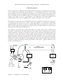
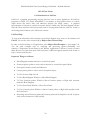
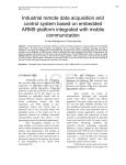
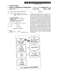
ENGG4420, REALTIME SYSTEMS DESIGN: LAB MANUAL Developed By Radu Muresan School of Engineering University of Guelph 2005, 2006, 2007 ______________________________________________________________ UNIVERSITY OF GUELPH ABSTRACT REAL-TIME SYSTEMS DESIGN: LAB MANUAL By Radu Muresan This manual was written to guide the students of the University of Guelph through the lab requirements for the ENGG4420 (Real-Time Systems Design) course. The manual is still under development and the author hopes that the students will understand this and help with suggestions and corrections. TABLE OF CONTENTS 1. Lab 1: Real-Time Simulation/Experimentation Lab .................................... 3 1.1 Lab Objectives ......................................................................................... 3 1.2 Lab Requirements .................................................................................. 4 1.3 Lab Report Outline................................................................................. 6 1.4 Plant Description..................................................................................... 7 1.5 DDC Algorithms and Their Implementation.................................... 9 1.6 An Overview of Heat Transfer ..........................................................11 1.7 Notes on the Design of Real-Time systems.....................................15 1.9 LabView Starter .....................................................................................19 2. Lab 2: Real-Time Embedded Application .....................................................27 2.1 Lab Objectives ......................................................................................27 2.2 Lab Introduction ...................................................................................27 2.3 Features of the S3C44BOX RISC Microcontroller........................28 2.4 Lab Requirements .................................................................................31 3. Lab 3 & 4: Embedded VoIP Phone................................................................35 3.1 Lab Objectives .......................................................................................35 3.2 Lab Introduction ...................................................................................35 3.3 Lab Requirements ................................................................................37 ENGG4420: Real-Time System Design; Lab Manual – By Radu Muresan ACKNOWLEDGMENTS The author wishes to acknowledge my graduate students Yang Zhanrong, Nupoor Shukla, Oliver Liu, and Matthew Mayhew that have contributed to the development of this manual. Special thanks to William Hohl of ARM Inc. for his continual support with the ARM products; to Dr. Khosrow Faranbakhsh for his help with the heat transfer topic; to the undergraduate class of Fall 2004 for their suggestions and projects; and to the undergraduate students that have experimented in their ENGG41xx projects with LabView and Embest boards. ii ENGG4420: Real-Time System Design; Lab Manual – By Radu Muresan Lab 1 1. REAL-TIME COMPUTER CONTROL SIMULATION/EXPERIMENTATION LAB USING LABVIEW AND ARM BOARDS 1.1 Lab Objectives Real-time embedded systems are difficult to develop and debug due to lack of realistic simulation, specifically, when implementing embedded systems that need to perform data acquisition, system control, and signal measurements. The goal of this lab is to introduce the students to the concept of simulation/experimentation of real-time computer control systems using LabView software and embedded boards. LabView is a powerful simulation and development software tool for industrial applications. In this lab, the students will learn two important principles that can be used in the development of the real-time computer control applications. These principles are: simulation of the environment of a control application through modeling, and experimentation through physical implementation of real-time control software. During the lab, the students will learn the basic usage of LabView software by modeling a simple plant – hot-air blower. They will build the system by using the built-in modules provided by the LabView software. They will simulate manual and auto functionality of the plant and implement a PID feedback control in C using LabView and an ARM based board called Embest. The simulation/experimentation technique will allow the students to develop and debug the real-time C implementation. Figure 1.0 presents the block diagram with the main components used in this lab. Fig. 1.0. Hardware components used in the simulation/experimentation lab. 3 ENGG4420: Real-Time System Design; Lab Manual – By Radu Muresan Design points: • Through LabView the designer can generate in real-time analog and digital signals; • The Embest S3CEV40 ARM provides an ADC that can be used to interface the Embest board with the real-time environment developed in LabView; • The real-time operating system uC/OS-II is installed on the Embest board and can be used for development of real-time tasks; • The NI PIC-6024E board is an A/D and D/A converter interface that works directly with the LabView software and can be used as a bridge between the LabView application and the Embest board. 1.2 Lab 1 Requirements A. Using the LabView software implement the manual control of the air-blower plant. The implementation should contain all of the elements necessary for the manual control. The implementation should display all of the input and output signals used in the plant (Weeks 1-2). B. Using the LabView software implement the auto control of the air-blower plant. The feedback control should implement the PID algorithm presented in Section 1.3 using a sampled control loop in a C-language control block. Use the examples presented in Section 1.4 to develop a realistic relation between the input variables (air flow), the output variables (the air temperature), and the control variables (current or voltage through resistor, air opening). Choose realistic values for your design (Weeks 1-2). C. Interface your LabView application with the Embest board by implementing the PID algorithm on the Embest board using simple data acquisition tasks (non-uC/OS-II approach). For the hardware connections between the Embest and NI boards you will need to do some wiring. Also, you should display your communication signals on the oscilloscope. They should look the same as the ones displayed through LabView. In order to complete these tasks refer to Lab 2, sections 2.2, 2.3, and 2.4.1 (Weeks 3-4). NOTES on Point C: • The ARM chip on the Embest board has only A/D converter. As a result, the analog outputs (signals such as current or voltage) from the Embest board to the NI board must be encoded as an 8 bit digital signals (0V, 5V levels) and wired from the I/O port to the NI board. These outputs will be interfaced with the digital I/O ports of the NI PIC-6024E board. 4 ENGG4420: Real-Time System Design; Lab Manual – By Radu Muresan • Use the LabView instruments to check the value of each digital input line and then convert the encoded signal value (8 bits) into its analog value equivalent. • The Embest I/O ports are multiplexed by other devices such as UART, LCD or SDRAM. Make sure that you select for your interface idle pins that are not used by other devices. D. Develop a lab report of minimum 8 pages and maximum 15 pages that describes your design and the LabView implementation. E. Present a working LabView design for the manual and auto modes of the air-blower plant to the TA. The maximum mark you can get for this lab is 14%. [Lab presentation: Week 1; Lab demo due on Week 5; Lab Report due on Week 5]. • Marking: Lab requirements: 2%; Lab Report 4%; LabView Demo (point B): 4%; Interface Demo (point C): 4%. 1.2.1 Example of Temperature Simulation and Note on How to Use C Code in LabView Note: For the purpose of writing C source code you will have to use the formula node. You will find this under the structures menu on the Functions palette. Formula Node. To add input and output to the Formula node select it on Block diagram, right click and then select add input or output. Implement area of blower and power of heater coil using the above formula node. NOTE: To calculate the output temperature you can derive your own relation. The following relation is given for your convenience: Formula: t2= (p/ (m*c)) +t; Where: t2 = output temperature; t = initial temperature assumed to be 21C; p = power of heater coil (p = R*I^2); m = mass of air; c= specific heat of air assumed to be 1.005. Mass of air = Area of blower * constant. Assume some realistic value for the constant. Area of blower = 0.5 * r * s; Where, r = radius of blower (assume some realistic value), s = Blower opening. 5 ENGG4420: Real-Time System Design; Lab Manual – By Radu Muresan To implement this formula you will have to use the formula menu under Arith/Compare on the Functions palette. Formula Define the above relation in this formula to get the output temperature. DAQ Assistant can be used to perform data acquisition. 1.3 Suggested Report Outline for Lab1 Try to present in your report all of the important things that are related to your implementation. Things that you are happy about the way you implemented or solved. Explain well your implementation and its functionality. The following is an outline that you can use. However, this outline is not mandatory; you can enhance it or tailor it to suit your application. 1. Introduction 1.1 Problem description 1.2 System requirements (similar to what I've presented in the lectures, but it can be simplified) 2. Background 2.1 Short overview of the benefits of using LabView in simulating this system. 2.2 Short description of the DDC (Direct Digital Control) for this system 2.3 Explain why this system is a real-time system 2.4 Explain the simulation/experimentation technique used in this lab and present its benefits. 3. Implementation 3.1 Present a top-down functional implementation of the system 3.2 Identify the functional modules and explain what type of real-time constraint they have Here you can use the information presented in the lecture 3.3 Present a system level block diagram for the manual mode Explain in detail the functionality of the manual mode. 3.4 Present a system level block diagram of the auto mode Explain in detail the functionality of the auto mode, the parameters used to control the loop. Justify why you choose to control the plant in this way. What are the parameters values used in designing the PID ... Observation on how these parameters affect the functionality of the plant. Present your simulation/experimentation design and explain the experiments conducted using the Embest board. Here you can present some functionality graphs that support your design. A. Appendix In the appendix you can add your detailed LabView diagrams, C code, extra functionality graphs that you like. The appendix can be as long as you want. The 3 main parts should be limited to 8 - 15 pages. 6 ENGG4420: Real-Time System Design; Lab Manual – By Radu Muresan 1.4 Plant Description The hot-air blower is a simple plant that illustrates various operations of a computer control system. Let us consider the hot-air blower shown in Figure 1.1. A centrifugal fan blows air over a heating element and into the tube. A thermistor bead is placed at the outlet end of the tube and forms one arm of the bridge circuit. The amplified output of the bridge circuit is available at B and provides a voltage, in the range of 0 to 10 V, proportional to the temperature. The current supplied to the heating element can be varied by supplying a DC voltage in the range 0 to 10 V at point A. The position of the air-inlet cover is adjusted by means of a reversible motor. The motor operates at a constant speed and is turned on or off by a logic signal applied to its controller; a second logic signal determines the direction of rotation. A potentiometer wiper is attached to the air-inlet cover and the voltage output is proportional to the position of the cover. Micro-switches are used to detect when the cover is fully open and fully closed. The operator is provided with a panel from which the control system can be switched from automatic to manual mode. In manual mode the heat output and cover position can be adjusted using potentiometers. Switches are provided to operate the fan and heater. Panel lights indicate fan on, heater on, cover fully open, cover fully closed, and auto/manual status. The desired output temperature (this is known as the set point for the control system) is set by the operator using a slider potentiometer, the setting of which can be read by the computer. The operator can also adjust the fan cover position. The operation of this simple plant using a computer requires that software be provided to support monitoring, control and actuation of the plant. A general schematic of the system is shown in Figure 1.2. On/Off Clockwise/ Anticlockwise Air Flow Tube Motor Control Blower Variable Air Inlet Bridge Circuit & Amplifier Thyristor Unit B Power Input Temperature Measurement (0-10V) A Fully Open Air Inlet Position Fully Closed Manual Operator Computer Auto Air Inlet Figure 1.1. A simple plant – a hot-air blower. 7 Man Heater ENGG4420: Real-Time System Design; Lab Manual – By Radu Muresan Monitoring involves obtaining information about the current state of the plant. In the above example the information is available from the plant instruments in the following two forms: 1. Analog signals: air temperature and fan-inlet cover position 2. Digital logic signals: fan-inlet cover position (fully open, fully closed); status signals: auto/manual, fan motor on, heater on. Computer Digital Input Air Air Inlet Inlet Clos Ope ADC Digital Output DAC To Operato r Bridg e Directio On / Auto/Manua Air Inlet Positio Heater Circuit Motor Contro Heater Elemen Air Flo Operato r Thermisto Blowe Air Inle Air Inlet Motor Figure 1.2. Computer control of a hot-air blower. 8 ENGG4420: Real-Time System Design; Lab Manual – By Radu Muresan Control involves the digital equivalent of continuous feedback control for the control of termperature (direct digital control, DDC) and for position control of the fan-inlet cover. Sequence and interlock control operations are also required since for the example, the heater should not be on if the fan is not running. The computer also has to handle automatic change-over from simply tracking (monitoring) the manual control operations to controlling the system when the operator request a change from manual to automatic control. This change over should be carried out without disturbing the temperature of the air at the output of the tube (a change-over which does not cause plant disturbance is referred to as a bumpless transfer). These actions may involve parallel logic operation, time-sequential control and timing of operations. Actuation requires provision of a voltage proportional to the demanded heat output to drive the heater control; logic signals indicating on/off, the direction in which the fan-inlet cover is to be moved and logic signals for the operator display. A simplified block diagram of a sampled feedback control system is shown in Figure 1.3. The computer control model for this application will have the following software tasks: plant input tasks; plant output tasks; and control tasks. e(nT) r(nT) Σ + Controlle r - u(nT) T c(nT) Hold (DAC) u(t) Plant c(t) Sampl e (ADC) T Figure 1.3. Simplified block diagram of a sampled feedback control system: c(nT), r(nT), e(nT), u(nT) are sampled values of c(t), r(t), e(t), u(t) at sample times nT where n is an integer and T is the sampling interval. In Figure 1.3, r(t) = set point, c(t) = controlled variable, e(t) = r(t) – c(t) = error, and m(t) = manipulated variable. 1.5 DDC Algorithms and Their Implementation t The differential equation for a PID controller is: m(t ) = K p [e(t ) + 1 / Ti ∫ e(t )dt + Td d (e(t ) / dt ] ; 0 where e(t) = r(t) – c(t), r(t) is the desired value (set point), c(t) the value of the variable being controlled and m(t) the output from the controller. The differential equation is the time domain representation of the controller. The equivalent frequency domain representation is: M ( s) 1 Gc ( s ) = = K p 1 + + Td s . E (s) Ti s In the frequency domain the overall system of the controller and plant can be represented by a block diagram as shown in Figure 1.4. 9 ENGG4420: Real-Time System Design; Lab Manual – By Radu Muresan R(s) E(s) + M(s) Gc(s) C(s) Gp(s) _ (a) R(s) E(s) C(s) M(z) + Gc(Z) Gp(s) _ T (b) sampling points Figure 1.4. General form of a control system: (a) continuous form; (b) discrete form Both time domain and frequency domain representations are continuous representations. To implement the controller using a digital algorithm we have to convert from a continuous to a discrete representation of the controller. There are several methods of doing this; the simplest is to use firstorder finite differences. Considering the time domain version of the controller we replace the differential and integral terms by their discrete equivalents by using the following relationships: df dt = k f k − f k −1 , ∆t n ∫ e(t )dt = ∑ ek ∆t k =1 e(n) − e(n − 1) 1 m(n) = K p Td + e(t ) + Ti ∆t ek ∆t ∑ k =1 n (1.1) where m(n) represents the value of m at some time interval n∆t where n is an integer. By introducing new parameters K i = K p (Ts / Ti ); K d = K p (Td / Ts ) ; where Ts = ∆t = the sampling interval, equation 1.1 can be expressed as an algorithm of the form: s (n) = s (n − 1) + e(n) m(n) = K p e(n) + K i s (n) + K d [e(n) − e(n − 1)] (1.2) where s(n) = the sum of the errors taken over the interval 0 to nTs. 10 ENGG4420: Real-Time System Design; Lab Manual – By Radu Muresan 1.6 An Overview of Heat Transfer The basic requirement for heat transfer is the presence of a temperature difference. The temperature difference is the driving force for heat transfer, just as the voltage difference is the driving force for electrical circuits. The heat transfer mechanisms are: conduction, convection, and radiation. Conduction is the transfer of energy from the more energetic particles of a substance to the adjacent, less energetic ones as a result of interactions between the particles. (Example: a cold canned drink in a warm room, eventually warms up to the room temperature as a result of heat transfer from the room through the aluminum can by conduction). Convection is the mode of energy transfer between a solid surface and an adjacent liquid or gas that is in motion and it involves the combined effects of conduction and fluid motion. Convection is called forced convection if the fluid is forced to flow over the surface by external means such as a fan, pump or wind. In contrast, convection is called natural (or free) convection if the fluid motion is caused by buoyancy forces induced by density differences due to the variation of temperature in the fluid. In our system we can apply the principles of heat transfer through forced convection. Despite the complexity of convection, rate of convection heat transfer is observed to be proportional to the temperature difference, and is conventionally expressed by Newton’s law of cooling as: . Q convection = hA(Ts − T∞ ) (1.3) where h is the convection heat transfer coefficient in W/m2*C), A is the surface area through which the convection heat transfer takes place, Ts is the surface temperature and T∞ is the temperature of a fluid sufficiently far from the surface. Note that at the surface, fluid temperature equals the surface temperature of the solid. The convection heat transfer coefficient h is not a property of the fluid. For forced convection of gases h = 25 – 250 W /(m 2 ⋅o C ) . Radiation is the energy emitted by matter in the form of electromagnetic waves (or photons) as a result of the changes in the electronic configuration of the atoms or molecules. Pipe and Duct Flow. The transport of liquids or gases in pipes and ducts is of great importance in many engineering applications. Flow through a pipe or a duct usually satisfies steady-flow conditions and thus can be analyzed as a steady-flow process. The steady-flow process is an idealized process which is defined as a process during which a fluid flows through a control volume steadily. The volume V, mass m and total energy content E of the control volume remain constant. Also, the heat and work interactions between a steady-flow system and its surroundings do not change with time. Thus, the power delivered by a system and the rate of heat transfer to or from a system remains constant during a steady-flow process. The mass balance for a general steady-flow system can be . . expressed in the rate form as: m in = m out (kg/s). During a steady-flow process, the total energy content of a controlled volume remains constant Ecv = constant. As a result the amount of energy entering a control volume in all forms (by heat, work, and mass) must be equal to the amount of . . energy leaving it: E in = E out . 11 ENGG4420: Real-Time System Design; Lab Manual – By Radu Muresan The following heat transfer problem examples can be used to model the temperature of air in the airduct plant. Note that these problems were taken from the reference book [2]. The air-blower plant can be considered as a steady-state flow problem with controlled volume. The control volume is the portion of the pipe that surrounds the resistor. 12 ENGG4420: Real-Time System Design; Lab Manual – By Radu Muresan 13 ENGG4420: Real-Time System Design; Lab Manual – By Radu Muresan 14 ENGG4420: Real-Time System Design; Lab Manual – By Radu Muresan 1.7 Notes on the Design of the Real-Time Systems You should use this example to develop the design and the report for this lab and the following labs. For the hot-air blower described in this lab it is assumed that the planning phase has been completed and a specification document has been prepared. The following is a short version of such document: A. Introduction The system comprises a set of hot-air blowers arranged along a conveyor belt. Several different configurations may be used with a minimum of 6 blowers and a maximum of 12. B. Plant Interface 15 ENGG4420: Real-Time System Design; Lab Manual – By Radu Muresan B.1. Input from plant Outlet temperature: analog signal, range 0 – 10 V, corresponding to 20C to 64C, linear relationship. B.2. Output to plant Heater control: analog 0 V to -10 V, corresponding to full heat (0 V) to no heat (-10 V), linear relationship. C. Control A PID controller with a sampling interval of 40 ms is to be used. (Note: Due to NI board sampling limitations this sampling interval may be changed to smaller rates). The controller parameters are to be expressed to the user in standard analog form that is proportional gain, integral action time, and derivative action time. The set point is to be entered from the keyboard. The controller parameters are to be variable and are to be entered from the keyboard. D. Operator communication D.1. Display General Settings Set temperature Actual temperature Error Heater output Other settings Date Controller settings :nn.n C :nn.n C :nn.n C :nn% FS Proportional gain Integral action Derivative action Sampling interval :dd/mm/yyyy Time :nn.n :nn.nn s :nn.nn s :nn ms :hh.mm The values on the display will be updated every 5 seconds. D.2. Operator input The operator can at any time enter a new set point or new values for the control parameters. This is done by pressing the ‘ESC’ key. In response to ‘ESC’ a menu is shown on the bottom of the display screen: : 1. Set temperature = nn.n 3. Integral action = nn.nn 5. Sampling interval = nn 7. Accept entries Select menu number to change 2. Proportional gain = nn.n 4. Derivative action = nn.nn 6. Management information 16 ENGG4420: Real-Time System Design; Lab Manual – By Radu Muresan In response to the number entered, the present value of the item selected will be deleted from the display and the cursor positioned ready for the input of a new value. The process will be repeated until item 7 is selected at which time the bottom part of the display will be cleared and the new values shown in the top part of the display. E. Management information On selection of item 6 the operator menu a management summary of the performance of the plant over the previous 24 hours will be given. The summary provides the following information: (a) Average error in C in 24 hour period. (b) Average heat demand %FS in 24 hour period. (c) For each 15 minute period: • Average demanded temperature; • Average error; and • Average heat demand (d) Date and time of output. F. General information There will be a requirement for a maximum of 12 control units. A single display and entry keyboard which can be switched between the units is adequate. Hardware Design There are many different possibilities for the hardware structure. Obvious arrangements are: 1. Single computer with multi-channel ADC and DAC boards. 2. Separate general purpose computers on each unit. 3. Separate computer-based microcontroller on each unit linked to a single general purpose computer. Each of these configurations needs to be analyzed and evaluated. Some points to consider are: Option1: given that the specification calls for the system to be able to run with a sample interval for the control loop of 40 ms, can this be met with 12 units sharing a single processor? Option 2: is putting a processor that includes a display and keyboard on each unit an expensive solution? Will communication between processors be required? (Almost certainly the answer to this is yes; operators and managers will not want to have to use separate display and keyboards.) Option 3: what sort of communication linkage should be used? A shared high-speed bus? A localarea network? Where should the microcontrollers be located? At each blower unit or together in a central location? 17 ENGG4420: Real-Time System Design; Lab Manual – By Radu Muresan Each option needs careful analysis and evaluation in terms of cost and performance. The analysis must include consideration of development costs, performance operating and maintenance costs. It should also include consideration of reliability and safety. To provide a basis for consideration of the widest range of approaches to software design we will assume that option 1 above is chosen. Software design Examining the specification shows that the software has to perform several different functions: • DDC for temperature control; • Operator display; • Operator input; • Provision of management information; • System start-up and shut-down; and • Clock/calendar function The various functions and type of time constraint are shown in the following figure. The control module has a hard constraint in that it must run every 40 ms. In practice this constraint may be relaxed a little to 40ms +-1 ms with an average value over 1 minute of, say, 40 ms +- 0.5 ms. In general the sampling time can be specified as Ts+-es with an average value, over time T, of Ts +-ea. The requirements may also be relaxed to allow, for example, one sample in 100 to be missed. These constraints will form part of the test specification. The clock/calendar module must run every 20 ms in order not to miss a clock pulse. This constraint can be changed into a soft constraint if some additional hardware is provided in the form of a counter which can be read and reset by the clock/calendar module. The constraint could now be, say, an average response time of 1 second with a maximum interval between reading the counter of 5 seconds. The operator display, as specified, has a hard constraint in that an update interval of 5 seconds is given. Common sense suggests that this is unnecessary and an average time of 5 seconds should be adequate; however, a maximum time would also have to be specified, say 10 seconds. Similarly soft constraints are adequate for operator input and for the management information logs. These would have to be decided upon and agreed with the customer. They should form part of the specification in the requirements document. The start-up module does not have to operate in realtime and hence can be considered as a standard interactive module. There are obviously several different activities which can be divided into subproblems. The subproblems will have to share a certain amount of information and how this is done and how the next stages of the design proceed will depend upon the general approach to the implementation. There are three possibilities: single program; foreground/background system; and muti-tasking. 18 ENGG4420: Real-Time System Design; Lab Manual – By Radu Muresan Hard time constraint (cyclic) Soft time constraint Control Clock/ calendar Operator display Cyclic Event Operator input Event/ cyclic Management information Interactive Shared data Start up 19 ENGG4420: Real-Time System Design; Lab Manual – By Radu Muresan 1.8 LabView Starter 1.8.1 Introduction to LabView LabView is a graphical programming language that uses icons to create applications. All LabView programs are called VI’s (virtual Instruments). User interface or front panel consists of controls (input devices like knobs, dials) and indicators (displays like LEDs, charts). A graphical representation of functions to control front panel objects is called code. The block diagram contains this code. Please check the LabView resources such as “Getting Started with the LabView” found on the Getting Started window of the LabView 8 software. LabView Help: To view more information about elements on the block diagram, move cursor to that element and Ctrl+H. You can also select context help by Help>>Show Context Help. In order to find useful help on VI applications select Help>>Find Examples to view sample VIs. You can study examples such as: Analyzing and processing signals>>Probability and statistics>>Temperature System Demo.vi and Industry Applications>>Process Control>>Control Mixer Process.vi to learn more about LabView features. Additional support material can be found on http://www.ni.com/labview/ Important Things at a Glance: • Block Diagram-contains functions to control front panel. • Functions palette- palette to select various functions to control front panel objects. • Front panel-contains controls and indicators. • Control palette-palette to select various front panel objects. • To View Context Help: Ctrl+H. • To View Block Diagram: Window>>Show Block Diagram. • To View Functions palette: Window>>Show Functions palette or Right click anywhere inside the Block Diagram. • To View Front Panel: Window>>Show Front Panel. • To View Controls palette: Window>>Show Controls palette or Right click anywhere inside the Front Panel. • Knowledge about Functions palette and Controls palette will be helpful for the lab. So please study various submenus of each carefully. 20 ENGG4420: Real-Time System Design; Lab Manual – By Radu Muresan 1.8.2 Building a VI To begin with LabView you will create a simple VI that generates a signal and displays it. After completing this exercise the block diagram and front panel of your VI will look like this. You can also find this exercise in “Getting Started with the LabView”. Block Diagram Front Panel 21 ENGG4420: Real-Time System Design; Lab Manual – By Radu Muresan Follow the following steps to create your first VI: 1. Launch LabView and select New in the LabView dialog box. 2. In the Create new list select Generate and Display under Tutorial (Getting Started). Click OK button to open the template. 3. Front panel appears with a graph. In the Controls palette locate the Numeric Controls palette. If the Controls palette is not visible, select Window>>Show Controls Palette. You will find different types of controls, indicators, buttons, LED1’s, graphs on the palette. 4. Click on Numeric Controls icon to access the Numeric Controls palette. Select the Knob control and place it on the front panel next to the graph. 5. To see the block diagram select Window>>Show Block Diagram. You will find Simulate Signal icon. It simulates a sine wave by default. Notice that the knob you selected in step 4 appears on it. 6. Right click on Simulate Signal to access its properties. You can select different signal types from the drop down menu. 7. Click OK to close the Configure Simulate Signal [Simulate Signal]. 8. Place cursor over the double- headed arrow of the Simulated Signal icon and drag the borders of Simulate Signal icon until Amplitude input appears. 9. The knob that you have selected in step 4 is used to control the amplitude of the sine wave. Move the cursor over the arrow of the Knob. Cursor becomes a wire spool or wiring tool. When Wiring tool appears click on the arrow and then click on the Amplitude input of Simulate Signal. Notice that wire appears and connects two objects. This completes the block diagram. Use Context Help to learn more about all the elements in the block diagram. 10. Select File>>Save to save this VI as example1.vi at a convenient location. 11. To Run this VI select Window>>Show Front Panel or by clicking the front panel. Click on the Run button. When the VI is running the Run button changes to a darkened arrow. You can also run a VI by Operate>>Run. 12. Move the cursor over the knob control and change the amplitude of the signal. 13. Click the STOP button to stop the VI or Operate>>STOP. 22 ENGG4420: Real-Time System Design; Lab Manual – By Radu Muresan 1.8.3 Building a VI from blank template: This VI compares operand 2 with operand 1 and determines if it is lesser, greater or equal to operand 1 and gives an LED indication about the same. It continues the comparison until the user stops the process. After completing this exercise the block diagram and front panel of your VI will look like this. Block Diagram Front Panel 23 ENGG4420: Real-Time System Design; Lab Manual – By Radu Muresan Follow the following steps to create the VI: 1. Launch LabView and select Blank VI from LabView dialog box. 2. From the problem description we find that we will need two numeric controls to input operand 1 and operand 2, some elements from Arithmetic&Comparison to compare if the numbers are greater, less than or equal to each other and three LEDs for the three conditions. 3. Select Numeric Ctrl from the Controls palette and place it on the front panel. Refer to steps 3 and 4 from example1. 4. On the block diagram this control appears with label Numeric. Right click it to access its Properties. In the Properties, change its label from Numeric to Operand1. 5. Repeat the steps 3 and 4 to create another control and name it as Operand 2. 6. To compare if Operand 1 is greater than Operand 2, go to the block diagram window and select appropriate expression from Comparison functions and place it on the block diagram. Read Context Help about the same. Connect Operand 1 to the x input and Operand 2 to the y input of the expression. Refer to step 9 in example 1 to wire the objects together using the wiring tool. 7. Select expression to compare if Operand 1 is less than Operand 2 and repeat step 7 to wire the inputs to the expression. 8. Select expression to compare if Operand 1 is equal to Operand 2 and repeat step 7 to wire the inputs to the expression. 9. You have to give LED indication for each of the cases. Go back to the front panel controls and place three LEDs on the front panel. Select LEDs from the Controls palette. 10. On the block diagram, connect the output of each of the above expressions to the LED input using the wiring tool. 11. Similar to step 4, access the Properties of each LED and change their labels to appropriately indicate greater, less or equal conditions. 12. Select File>>Save to save this VI as example2.vi at a convenient location. 13. If you have followed all the steps correctly, you will see a solid white arrow on the Run button. A broken arrow indicates that there are some errors. Click on the broken arrow to see the Error list. Refer to Help and correct the errors. 14. Run your VI. You will notice that the program runs only once and then stops. We want to design a VI, which continues to Run until the user stops it. Notice that there is no condition on the block diagram that indicates this feature. 24 ENGG4420: Real-Time System Design; Lab Manual – By Radu Muresan 15. On the Functions palette, select an Execution Control, which continues to execute until a condition is true. This functionality can be achieved by a While Loop. 16. Place the Loop on the block diagram such that all the elements including (2 numeric controls, 3 expressions, 3 LEDs) are inside the loop. In order to do this, select While Loop function, left click on the top left corner of the block diagram, keeping the mouse pressed drag and increase the dotted loop until all the elements are inside the loop. 17. Notice that a Stop button appears which is connected to the Stop condition of the while loop. You can configure the stop condition by right clicking the stop sign and choosing the appropriate condition. For your example select the Stop if True condition. Similar to step 5, change the label of the Stop button to On/Off. Notice the STOP button appears on the front panel. 18. Save changes to your VI and Run it again. 19. Notice that this time the VI runs continuously and stops only if the On/Off button is clicked. This is because of the While loop you have included in your design. 1.8.4 For the lab: The main inputs and outputs for the lab are blower arc length, reference temperature, heater current, control for automatic/manual mode of operation, main control to turn On/Off the system, fan on and heater on. Keep the Context Help open at all times while doing the lab. Please follow the following steps: 1. Launch LabView and select New in the LabView dialog box. Select Blank VI in the Create new list. Click OK to open the template. 2. As in example 2, design a control such that the process continues until the user stops it. Refer to Step 15 in example 2. 3. The user can change the opening of the fan cover. Implement a control to achieve this functionality. Depending on the opening certain mass of air blows over the heating element. Implement this calculation of mass of air blowing over the heating element using a simple C code. Search for a feature, which lets you, implement C code. 4. The current flowing through the heating coil can also be varied. The resistance of the coil is considered to be constant. Similar to step 3, you can implement the power calculation using a simple C code. 5. The output temperature depends on the airflow and the current flowing through the coil. For a constant heater current, if the airflow increases then the output temperature drops. If the airflow remains constant then the output temperature increases with the increase in heater 25 ENGG4420: Real-Time System Design; Lab Manual – By Radu Muresan current. Determine a relation between these factors. You can implement this formula. Refer to Functions palette for the appropriate menu. 6. The control action to be taken depends on the mode of operation of the system i.e. if the system is in automatic or manual mode of operation. So the next step would be to determine the mode of operation. You can implement a toggle switch for this purpose. Find a Function, which lets you do this Case selection. 7. Within the automatic mode case you have to implement the PID algorithm using C language. Refer to the same block you have used in steps 3 and 4. Comparing the output of this C block and the reference temperature, some control action has to be taken. 8. In this case we will control only the heater current. If the output temperature is greater than reference temperature then your control block should reduce the heater current. The important thing in this step is the feedback. Whether the output temperature exceeds the reference temperature is given as a feedback to the control block. 9. Within the manual mode case we will control the blower arc length and heater current. The output temperature from step 5 is once again compared with reference temperature. If the user has kept the settings such that the output temperature exceeds the reference temperature then you will display a message to the user and prompt him for an input to change the arc length and heater current suitably. You will find a block to display and prompt user for an input on the Functions palette>>All Functions>>Time & Dialog. 10. If the number entered by the user is positive then it increases the arc length and vice versa. Similar to step 8 you will have to implement a feedback loop, which will reflect this new arc length. 11. To indicate the Blower on and heater on conditions, you will have to implement two LED indicators on the front panel (Control palette>>LED’s). If the arc length and heater current are greater than zero, then the LEDs are switched on to indicate that both fan and heater current are on. 26 ENGG4420: Real-Time System Design; Lab Manual – By Radu Muresan Lab2 2. REAL-TIME EMBEDDED APPLICATION 2.1 Lab Objectives I believe that in an engineering environment students should learn the mechanisms of developing applications based on commercial real-time operating systems (RTOS). As a result, the main goal of this lab is to introduce the students to embedded development environment that will be used to develop RTOS based applications. uC/OS-II is a real-time preemptive multitasking kernel. It is written in C with the exception of a small CPU-specific assembly module. This means that uC/OS can be ported easily to different processors. In fact, it has been ported to a large number of processors ranging from simple 8-bit controllers like 8051 to large 32-bit CPUs. The good thing about the uC/OS-II is that it is completely documented by the author (Jean J. Labrosse) in its book “MicroC/OS-II, The Real-Time Kernel Second Edition”. Also, the uC/OS-II kernel is simple and has been used in various commercial products. The embedded development platform used in this lab is the Embest Development System for ARM. The Embest Development System is simple, cost effective and suitable for a university environment. The tools provide a complete software and hardware package that can be used in developing complex practical implementations. I have chosen these tools based on these facts and due to the fact that all of the hardware interfaces are supported by working examples. This allows the students to focus on more complex applications; they don’t have to spend a lot of time in writing low level interfacing programs. Also, Embest has ported the uC/OS-II to the development board and has provided some programming examples that use the uC/OS-II real-time kernel. This lab and the next labs, in this manual,will be based on the “Embedded System Development and Labs; English Edition, 2005” Edited by Radu Muresan. At this time the book is available only in electronic format. However, there will be two hardcopies of the book present in the lab class and one at the library. 2.2 Lab Introduction ARM architectures are well known for their low-power consumption features and for the Thumb instruction set. ARM Inc. is a chipless company. However, the ARM processor cores are adopted by many leading semiconductor companies such as TI, Philips, Intel, Samsung, etc. ARM has established its lead position in the embedded technologies and due to its low-power design features it is widely used in the wireless and portable applications. In 2002, ARM processors occupied 79.5% of the 32-bit and 64-bit microprocessor market in the world. Nowadays, ARM processors are almost in everybody’s pocket because almost all of the mobiles phones and PDAs are developed based on ARM cores. The Embest Development Tools for ARM use a development board based on the Samsung’s S3C44BOX 16/32-bit RISC microprocessor. The Samsung S3C44BOX was developed using an ARM7TDMI core, 0.25 um CMOS standard cells and a memory compiler. Its low-power and fully 27 ENGG4420: Real-Time System Design; Lab Manual – By Radu Muresan static design is particularly suitable for cost-sensitive and power sensitive applications. The main feature of the S3C44BOX is its CPU core, a 16/32-bit ARM7TDMI RISC processor (66 MHz). The architectural enhancements of ARM7TDMI include Thumb decompressor, an on-chip ICE breaker debug support and a 32-bit hardware multiplier. By providing a complete set of common system peripherals, the S3C44BOX minimizes overall system costs and eliminates the need to configure additional components. The following are the integrated on-chip functions that are described in the User’s Manual. Most of these features are explained in the “Embedded System Development and Labs” book with practical examples. • • • • • • • • • • • • • • 2.5 Static ARM7TDMI CPU core with 8Kb cache. (SAMBA II bus architecture up to 66MHz; External memory controller. (FP/EDO/SDRAM Control, Chip Select logic); LCD controller (up to 256 color DSTN) with 1-ch LCD-dedicated DMA; 2-ch general DMAs / 2-ch peripheral DMAs with external request pins; 2-ch UART with handshake (IrDA1.0, 16-byte FIFO) / 1-ch SIO; 1-ch multi-master IIC-BUS controller; 1-ch IIS-BUS controller; 5-ch PWM timers & 1-ch internal timer; Watch Dog Timer; 71 general purpose I/O ports / 8-ch external interrupt source; Power control; Normal, Slow, Idle, and Stop mode; 8-ch 10-bit ADC; RTC with calendar function; On-chip clock generator with PLL. 2.3 Features of the S3C44BOX RISC Microcontroller Architecture • • • • • • Integrated system for hand-held devices and general embedded applications; 16/32-Bit RISC architecture and powerful instruction set with ARM7TDMI CPU core; Thumb de-compressor maximizes code density while maintaining performance; On-chip ICEbreaker debug support with JTAG-based debugging solution; 32x8 bit hardware multiplier; New bus architecture to implement Low-Power SAMBA II (Samsung' ARM CPU embedded Micro-controller Bus Architecture); System Manager • • • • • Little/Big endian support; Address space: 32Mbytes per each bank (Total 256 Mbytes); Supports programmable 8/16/32-bit data bus width for each bank; Fixed bank start address and programmable bank size for 7 banks; 8 memory banks: o 6 memory banks for ROM, SRAM etc. 28 ENGG4420: Real-Time System Design; Lab Manual – By Radu Muresan • • • • o 2 memory banks for ROM/SRAM/DRAM (Fast Page, EDO, and Synchronous DRAM); Fully Programmable access cycles for all memory banks; Supports external wait signal to expend the bus cycle; Supports self-refresh mode in DRAM/SDRAM for power-down; Supports asymmetric/symmetric address of DRAM. Cache Memory & Internal SRAM • • • • • • 4-way set associative ID(unified)-cache with 8Kbyte; The 0/4/8 Kbytes internal SRAM using unused cache memory; Pseudo LRU(Least recently used) Replace Algorithm; Write through policy to maintain the coherence between main memory and cache content; Write buffer with four depth; Request data first fill technique when cache miss occurs; Clock & Power Manager • • • • • Low power; The on-chip PLL makes the clock for operating MCU at maximum 66MHz; Clock can be fed selectively to each function block by software; Power mode: Normal, Slow, Idle and Stop mode. Normal mode: Normal operation mode; Slow mode: Low frequency clock without PLL; Idle mode: Stop the clock only for CPU; Stop mode: All clocks are stopped; Wake up by EINT[7:0] or RTC alarm interrupt from Stop mode. Interrupt Controller • • • • • 30 Interrupt sources; (Watch-dog timer, 6 Timer, 6 UART, 8 External interrupts, 4 DMA, 2 RTC, 1 ADC, 1 IIC, 1 SIO); Vectored IRQ interrupt mode to reduce interrupt latency; Level/edge mode on the external interrupt sources; Programmable polarity of edges and level; Supports FIQ (Fast Interrupt request) for very urgent interrupt request. Timer with PWM (Pulse Width Modulation) • • • • 5-ch 16-bit Timer with PWM / 1-ch 16-bit internal timer with DMA-based or interruptbased operation; Programmable duty cycle, frequency, and polarity; Dead-zone generation; Supports external clock source. 29 ENGG4420: Real-Time System Design; Lab Manual – By Radu Muresan RTC (Real Time Clock) • • • • Full clock feature: msec, sec, min, hour, day, week, month, year; 32.768 KHz operation; Alarm interrupt for CPU wake-up; Time tick interrupt. General-Purpose input/output Ports • • 8 external interrupt ports; 71 multiplexed input/output ports. UART • • • • • • • 2-channel UART with DMA-based or interrupt based operation; Supports 5-bit, 6-bit, 7-bit, or 8-bit serial data transmit/receive; Supports H/W handshaking during transmit/receive; Programmable baud rate; Supports IrDA 1.0 (115.2 kbps); Loop back mode for testing; Each channel have two internal 32-byte FIFO for Rx and Tx; DMA Controller • • • • • • 2 channel general purpose Direct Memory Access controller without CPU intervention; 2 channel Bridge DMA (peripheral DMA) controller; Support IO to memory, memory to IO, IO to IO with the Bridge DMA which has 6 type’s DMA requestor: Software, 4 internal function blocks (UART, SIO, Timer, IIS), and External pins; Programmable priority order between DMAs (fixed or round-robin mode); Burst transfer mode to enhance the transfer rate on the FPDRAM, EDODRAM and SDRAM; Supports fly-by mode on the memory to external device and external device to memory transfer mode. A/D Converter • • 8 channel multiplexed ADC; Max. 100KSPS/10-bit. LCD Controller • • Supports color/monochrome/gray LCD panel; Supports single scan and dual scan displays; 30 ENGG4420: Real-Time System Design; Lab Manual – By Radu Muresan • • • • • • Supports virtual screen function; System memory is used as display memory; Dedicated DMA for fetching image data from system memory; Programmable screen size; Gray level: 16 gray levels; 256 Color levels. Watchdog Timer • • 16-bit Watchdog Timer; Interrupt request or system reset at time-out. IIC-BUS Interface • • 1 channel Multi-Master IIC-Bus with interrupt-based operation; Serial, 8-bit oriented, bi-directional data transfers can be made at up to 100Kbits/s in the standard mode or up to 400 Kbits/s in the fast mode. IIS-BUS Interface • • • 1 channel IIS-bus for audio interface with DMA-based operation; Serial, 8/16bit per channel data transfers; Supports MSB-justified data format. SIO (Synchronous Serial I/O) • • • 1 channel SIO with DMA-based interrupt-based operation; Programmable baud rates; Supports serial data transmit/receive operations 8-bit in SIO. Operating Voltage Range / Operating Frequency / Package • • • Core: 2.5V I/O: 3.0V to 3.6V; Up to 66 MHz; 160 LQFP / 160 FBGA 2.4 Lab 2 Requirements Throughout this Chapter you will need to refer to the “Embedded System Development and Labs, English Edition” book. 2.4.1 Introduction to the Real-Time Embedded ARM Development System In this part of the lab you will get familiar with the Embest Development System and learn how to use the software tools. Specifically, you will learn how to create projects, how to compile assembly 31 ENGG4420: Real-Time System Design; Lab Manual – By Radu Muresan and C language programs, how to link the object files, how to initialize the system, how to debug your applications, etc. Also, you will learn basic programming methods and interfacing for common peripherals. Feel free to experiment with the hardware and software tools and learn as much as possible about the tools and about the microcontroller and its peripherals. The following are the lab requirements for this part: 1. Study Chapter 2 of the “Embedded System Development and Labs” book. 2. Perform ARM Assembly Instruction Lab 1 of Section 3.1, C Language Program Lab 1 of Section 3.5, C Language Program Lab 1 of Section 3.6, and Sum up Programming Lab of Section 3.8. (Note: The exercise sections are not required). 3. Perform the labs of Chapter 4 (Note: The exercise sections are not required). These labs are in order: Memory Lab; I/O Interface Lab; Interrupt Lab; Serial Communication Lab; RealTime Timer Lab; 8-SEG LED Display Lab. 4. Perform the labs of Chapter 5 (Note: The exercise sections are not required). These labs are: LCD Display Lab; 4x4 Keyboard Control Lab; Touch Panel Control Lab. 5. Talk to your TA when you have completed this part. 2.4.2 Example: MicroC/OS-II Implementation of a Start-Stop Watch (One Week) In this part of the lab you will learn how to port the MicroC/OS-II Kernel to the S3C44BOX ARM based microcontroller and how to write simple application programs that use the uC/OS-II kernel. Also, you will learn to develop projects using the uC/OS-II kernel. The following are the requirements for this part: 1. Perform the uC/OS Porting Lab of Section 7.1 (Note: The exercise section is not required). 2. Perform the uC/OS Application Lab of Section 7.2 (Note: The exercise section is not required). 3. Perform the uC/OS Start-Stop Watch application example of Section 7.3. This example was developed based on the Stop-Watch application presented in the “Embedded Microcontrollers” by Todd D. Morton. 4. Talk to your TA when you have completed this part. 2.4.3 Implementation Requirements for an Intruder Alarm System (Two Weeks) In this part of the lab you will use the knowledge gained so far and implement an “Intruder Alarm System” using the functions of the uC/OS-II real-time kernel. The requirements of this part can be also found in Section 7.3.4 of the lab book. The following describes the requirements of the Intruder Alarm System implementation. Intruder Alarm Description An intruder alarm system receives information about the state of the monitored building from a number of sensors located at every possible entrance and exit. Sensors function basically as switches, indicating whether a given sensor has detected an intruder or not. The alarm is located inside the building. It is set (armed) and reset (disarmed) from inside the building. A digital code of fixed length is required for both setting and resetting the alarm. One of the entrances, which also functions as an exit, is nominated as the entrance and the exit after the alarm has been set. 32 ENGG4420: Real-Time System Design; Lab Manual – By Radu Muresan Timing information is crucial for proper functioning of an intruder alarm. When the alarm is initially set, a specific time delay is allowed for the user to leave the building through the nominated exit. When the alarm is set, the use of any of the entrances other than the nominated one for re-entry activates the alarm instantly or, at most, within a matter of a few seconds. The sensors monitoring the entrance nominated for re-entry and the route to the alarm control point do not activate the alarm until a set time has elapsed. This set time allows the user to enter the building and disarm the alarm by entering the correct digital code. If this is not done successfully, the alarm is activated at the end of the set time. The alarm system has a siren and a strobe and these are located outside the building. If an intruder is detected or the alarm is not disarmed by the person entering the building through the nominated entrance during the required time, the siren begins to sound and the strobe begins to flash immediately, as mentioned above. In this event, the siren continues to sound for a specified time, usually for a few minutes and stops, but the strobe continues to flash. The alarm can be reset by the user only by entering the correct code. If the alarm has already been triggered this would turn the alarm off. The correct code is the most up to date code entered when arming the system. When entering the code for disarming the alarm, the user is allowed a maximum period to complete the task. If the user fails to complete this within the given time, the system discards the partial entry and waits for the next attempt. The user is allowed as many attempts as possible to enter the correct code within the allocated time. If the alarm has already been set off, after this period it cannot be reset except by an appointed independent authority. Some reasonable limiting values for the timing parameters involved are: a. Time allowed for setting the alarm and leaving the building – 30 seconds b. Time between detecting an intruder and triggering the alarm off – 5 seconds c. Time allowed for re-entry through the nominated entrance and start resetting the alarm – 2 minutes d. Duration for resetting the alarm after re-entry – 1 minute e. Maximum duration for entering the code at each attempt – 20 seconds f. Duration of the siren sound – 5 minutes NOTE1: In this application you can use the keypad in order to simulate the entrance and exit switches; the 8-SEG LED or the LCD to perform the flashing; the earphone to simulate the siren sound. NOTE2: Use the statistics task OS_TaskStat() to analyze the CPU usage of your application. Present an analysis of the CPU usage in your report and explain the task priority assignment in your system. NOTE3: For deciding the task priorities you can use the RMS (Rate Monotonic Scheduling) technique (See the Lecture Notes). 2.4.4 Lab Marking A. The maximum lab mark that you can obtain for this lab is 10%. The lab mark includes: performing the steps presented in Sections 2.4.1 and 2.4.2, implement the intruder alarm system. B. Talk to your TA after finalizing Sections 2.4.1 and 2.4.2. Show to your TA that you understand the basics presented in these sections. The accomplishment of the steps presented in these sections will be marked by 2% of the total lab mark. 33 ENGG4420: Real-Time System Design; Lab Manual – By Radu Muresan C. Develop a lab report of minimum 8 pages and maximum 15 pages that describes your design and the intruder alarm implementation. The report should have three main parts: introduction, background, and implementation design. The introduction and the background should be short; your main focus should be on the design of your lab application. The maximum mark for this part is 8%. The final mark will be based on your report and on the demo of your implementation. Each part (report and demo) will weigh 1/2 of the total mark for this part. a. Marking: Lab requirements: 2%; Lab Report 4%; Lab Demo: 4%. 2.4.4 Suggested Report Outline for Lab 2 Try to present in your report all of the important things that are related to your implementation. Things that you are happy about the way you implemented or solved. Explain well your implementation and its functionality. The following is an outline that you can use. This outline is not mandatory and you can enhance it or tailor it to suit your application. Make sure that you identify all your tasks, task requirements and their type (hard, soft, interactive) 1. Introduction 1.1 Problem description 1.2 System requirements 2. Background 2.1 Short description of the embedded platform used and the benefits of using an ARM based controller 2.2 Short overview of the benefits of using uC/OS in developing a real time application. 2.3 Explain why this system is a real-time system 3. Implementation 3.1 Present a top-down functional implementation of the system 3.2 Identify the tasks, objects and services needed to implement this system. 3.3 Present a block diagram of your implementation Show the interconnection and the communication between all your tasks. Explain in detail the functionality of your implementation. Explain the testing procedures that you used to make sure that the real-time system works and all of the constraints are met. Here you can present some simulation (testing) results. A. Appendix Present your project structure and present your complete C code for your implementation. Note. The appendix can be as long as you want. The 3 main parts should be limited to 8 - 15 pages 34 ENGG4420: Real-Time System Design; Lab Manual – By Radu Muresan Lab3 and 4 3. EMBEDDED VOIP PHONE 3.1 Lab Objectives The goal of this lab is to teach the students how to implement a complex real-time embedded application using the uC/OS-II real-time kernel. The application that students will implement in this lab is an embedded VoIP phone. The students will use the Embest development system to develop embedded VoIP phone. A working VoIP embedded phone should be able to perform duplex phone communication with the other boards. At the end of the labs all of the boards will be connected through an Ethernet switch and students will prove the functionality of their implementation by performing duplex communications with other boards. 3.2 Lab Introduction Due to intense research into the VoIP technology, there are a large number of commercial VoIP products in the market today. VoIP or Voice over Internet Protocol, is a method for taking analog audio signals like the kind you hear when you talk on the phone and turning them into digital data that can be transmitted over the internet. There are three different flavors of VoIP service in use today: • ATA (Analog Telephone Adaptor): The ATA allows you to connect a standard phone to your computer or your internet connection for use with VoIP. The ATA is an analog to digital converter. It takes the analog signal from your traditional phone and converts it into digital data for transmission over the internet. Providers such as Vonage and AT&T CallVantage are bundling ATAs free with their services. • IP Phones – These specialized phones look just like normal phones with a handset, cradle and buttons. But instead of having the standard RJ-11 phone connectors, IP phones have an RJ-45 Ethernet connector. IP phones connect directly to your router and have all the hardware and software necessary right onboard to handle the IP call. Soon, Wi-Fi IP phones will be available, allowing subscribing callers to make VoIP calls from any Wi-Fi hot spot. • Computer-to-Computer – This is certainly the easiest way to use VoIP. You don’t even have to pay for long-distance calls. There are several companies offering free or very low-cost software that you can use for this type of VoIP. All you need is the software, a microphone, speakers, a sound card and an internet connection. Cisco IP phones have become an instant favorite of many companies, educational institutions and other organizations. The advantage of deploying these phones results in direct price saving, as lines do not have to be leased from phone companies. The 7900 Series IP phones from Cisco offers a host of features and advanced customization options. These phones are connected through a virtual 35 ENGG4420: Real-Time System Design; Lab Manual – By Radu Muresan LAN, which guarantees adequate bandwidth for communications. Also, there is support for features such as XML (Extensible Markup Language) that enables users to access services such as directories, stock quotes etc. Typical Cisco IP phones are shown in the following figure. Figure 3.1 Cisco IP Phones. The VoIP Phone System: Packet Switching Data networks do not use circuit switching. Your Internet connection would be a lot slower if it maintained a constant connection to the Web page you were viewing at any given time. Instead, data networks simply send and retrieve data as you need it. And, instead of routing the data over a dedicated line, the data packets flow through a chaotic network along thousands of possible paths. This is called packet switching. While circuit switching (used in switching telephony) keeps the connection open and constant, packet switching opens a brief connection – just long enough to send a small chunk of data, called a packet, from one system to another. Packet switching is very efficient. It lets the network route the packets along the least congested and cheapest lines. It also frees up the two computers communicating with each other so that they can accept information from other computers, as well. VoIP technology uses the Internet’s packet-switching capabilities to provide phone service. VoIP has several advantages over circuit switching. For example, packet switching allows several telephone calls to occupy the amount of space occupied by only one in a circuit-switched network. Using 36 ENGG4420: Real-Time System Design; Lab Manual – By Radu Muresan PSTN (Public Switched Telephone Network), that 10-minute phone call we talked about earlier consumed 10 full minutes of transmission time at a cost of 128Kbps. With VoIP, the same call may have occupied only 3.5 minutes of transmission time at a cost of 64Kbps, leaving another 64Kbps free for that 3.5 minutes, plus an additional 128 Kbps for the remaining 6.5 minutes. Based on this simple estimate, another three or four calls could be easily fit into the space used by a single call under the conventional system. And this example doesn’t even factor in the use of data compression, which further reduces the size of each call. 3.3 Lab Requirements 3.3.1 Preparatory Examples In this part of the lab you will use the “Embedded System Development and Labs” book and you will learn how to download a file to the development board through an Ethernet connection and how to store a wav file using the IIS interface. The following are the requirements for this part: 1. Perform the IIC Serial Communication Lab of Section 6.1 (Note: The exercise section is not required). 2. Perform the Ethernet Communication Lab of Section 6.2 (Note: The exercise section is not required). 3. Perform the IIS Voice Interface Lab of Section 6.3 (Note: The exercise section is not required). 4. Talk to your TA when you have completed this part. 3.3.2 Implementation Requirements for the VoIP Embedded Phone In this part you have to develop a complete VoIP embedded phone using the MicroC/OS-II RTOS and the Embest Development System. The functional requirements of the phone are: • Use the key pad to introduce a group number to be called • Use the key pad to send a short message to a group connected to • Broadcast your phone status (online/busy) to other groups • Use the LCD to display the group number connected to • Use the LCD or UART0 to display the time passed while connecting with a MAC address • List all the online groups • Caller ID • Answer machine (option) • Use the microphone and the earphones to perform a duplex audio communication 37 ENGG4420: Real-Time System Design; Lab Manual – By Radu Muresan Phone Protocol in the Lab 1. You have to setup your own NIC MAC address in the format of: 00-20-05-44-20-XX, in which XX is your group number. For example, your group number is 12, then you should use 00-20-05-4420-12 as your NIC MAC address. 2. The message format should be in the format of: “MESSAGE TYPE + MESSAGE”. MESSAGE TYPE is the first byte of your data to be sent. • 0x10: Broadcast AVAILABLE, followed by your group number. • 0x11: Broadcast BUSY, followed by your group number. • 0x12: REQUEST a connection, followed by the group number to be connected. • 0x13: ACCEPT a connection, followed by your group number. • 0x14: Send a TEXT MESSAGE, followed by the text message. • 0x15: Send VOICE DATA, followed by the voice data. 38 ENGG4420: Real-Time System Design; Lab Manual – By Radu Muresan • 0x16: Indicates the END of data pertaining to a recorded voice sample. • 0x17: CLOSE a connection, followed by your group number. 3.3.2 Implementation Requirements for the VoIP Embedded Phone (NOTE: this part is not complete. More details will be presented later) In this part you have to develop a complete VoIP embedded phone using the MicroC/OS-II RTOS and the Embest Development System. The minimum functional requirements of the phone are: • Use the key pad to introduce the IP address called • Use the LCD to display the IP address connected to • Use the LCD and the 8-SEG LED to display the time passed while conversing with an IP address • Use the microphone and the earphones to perform a duplex audio communication 3.3.3 Lab Marking D. The maximum lab mark that you can obtain for this lab is 16%. The lab mark includes: performing the steps presented in Section 3.3.1, implement the VoIP embedded phone, connect your phone to the lab network. E. Talk to your TA after finalizing Section 3.3.1. Show to your TA that you understand the basics presented in this section. The accomplishment of the steps presented in these sections will represent 2% of your total lab mark. 39 ENGG4420: Real-Time System Design; Lab Manual – By Radu Muresan F. Develop a lab report of minimum 10 pages and maximum 20 pages that describes your design and the VoIP embedded phone application. The report should have three main parts: introduction, background, and implementation design. The introduction and the background should be short; your main focus should be on the design of your lab application. The maximum mark for this part is 12%. The final mark for this part will be based on your report and on the demo of your implementation. Each part (report and demo) will weigh 1/2 of the total mark for this part. NOTE: Provide the Petri Net diagram for the implementation. Also, you should use again the statistics task and analyze the efficiency of your system. G. For the demo part, connect your VoIP embedded phone to the lab network and perform duplex connections with the TA’s board. Try to implement the whole functionality of the VoIP phone. Your implementation should present the duplex text communication. As for the voice communication, your implementation should at least be able to send the sample wav file. We will mark this lab relative to the best implementations. a. Marking: Lab requirements: 2%; Lab Report: 6%; Lab Demo: 6%; Petri Net: 2%. NOTE 1: Provide the Petri Net diagram for the implementation. NOTE 2: Use the statistics task OS_TaskStat() to analyze the CPU usage of your application. Present an analysis of the CPU usage in your report and explain the task priority assignment in your system. NOTE 3: For deciding the task priorities you can use the RMS (Rate Monotonic Scheduling) technique (See the Lecture Notes). 3.3.4 Suggested Report Outline for Lab 3&4 You need to present only one report for both labs. Try to present in your report all of the important things that are related to your implementation. Things that you are happy about the way you implemented or solved. Explain well your implementation and its functionality. The following is an outline that you can use. This outline is not mandatory and you can enhance it or tailor it to suit your application. Make sure that you identify all your tasks, task requirements and their type (hard, soft, interactive) 1. Introduction 1.1 Problem description 1.2 System requirements 2. Background 2.1 Short description of the embedded platform used and the benefits of using an ARM based controller 2.2 Short overview of the benefits of using uC/OS in developing the VoIP phone. 2.3 Explain why this system is a real-time system 3. Implementation 3.1 Present a top-down functional implementation of the VoIP phone. 3.2 Present a Petri Nets functional diagram of your VoIP phone. Explain the functionality of the diagram and provide the reachability tree. 3.3 Identify the tasks, objects and services needed to implement this system. 3.4 Present a block diagram of your implementation Show the interconnection and the communication between all your tasks. Explain in detail the functionality of your implementation. Explain the testing procedures that you used to make sure that the real-time system works and all of the constraints are met. Explain the CPU usage results, by using the statistics task OS_TaskStat(). Here you can present some simulation (testing) results. 40 ENGG4420: Real-Time System Design; Lab Manual – By Radu Muresan 4. Conclusions. Briefly present the main conclusions of the lab results. A. Appendix Present your project structure and present your complete C code for your implementation. Note. The appendix can be as long as you want. The 3 main parts should be limited to 8 - 15 pages APPENDIX A Embest S3CEV40 Evaluation Board ARM - Samsung S3C44B0X EVB ------10 BaseT, USB, 2x RS232, LCD, Boot Code, uCos, ucLinux ... Embest S3CEV40 EVB for S3C44B0X is a platform that is suitable for code development of Samsung's S3C44B0X 16/32-bit RISC microcontroller (General ARM) for hand-held device and general applications. S3C44B0X consists of 16-/32-bit RISC (ARM7TDMI) CPU core, 8KB cache, optional internal SRAM, LCD controller (up to 256 color DSTN), 2-ch UART with hand-shake (IRDA1.0,16byte FIFO), 4-ch DMA, System manager (chip select logic, FP/ EDO/SDRAM controller), 6ch timers with PWM, 71-bit general purpose I/O ports, RTC, 8-ch 10-bit ADC, IIC-BUS interface, IIS-BUS interface, Sync. SIO interface and PLL for clock. Embest S3CEV40 EVB consist of S3C44B0X, boot Flash, SDRAM, LCD&TSP touch screen interface, two serial communication ports, ethernet interface, USB interface, keyboard interface, IIS(sound) interface, exterior IDE port, Nand Flash, RTC, JTAG interface and 8SEG. Embest S3CEV40 EVB provide a high performance and low cost solution for embedded engineers. Hardware specification 41 ENGG4420: Real-Time System Design; Lab Manual – By Radu Muresan • Dimensions: 190 x 190 mm(main board) • 5.0V DC or USB power supply • 2 M bytes 16-bit Flash • 8 M bytes 16-bit SDRAM • 4K bit EEPROM with IIC BUS • 2x RS232 • USB connecter • 10M Ethernet interface connector • microphone import • IIS audio frequency export (speaker out) • 16 M Bytes Nand Flash • external IDE port • LCD&TSP touch screen port • 320×240 LCD * (optional) • 4×4 keyboard * (optional) • Reset button • 2 interrupt buttons and 2 LEDS • 8 segment leds • 20-pin JTAG interface connector • 4 groups 2×20 PIN expansion connectors of CPU Software Specification • Boot software • Samples codes and test software(All in source code) o learning example for arm assemble instructions o learning example for running arm processor in different operating mode o learning example for arm thumb instructions o learning example on how to operate with interrupt o IIS sounds test program o Test porgram for 8_segment Led, to light as 1,2,3,... o Test program for using RTC 42 ENGG4420: Real-Time System Design; Lab Manual – By Radu Muresan o Test program on how to access memory o Test program to lighting LED, showing how to use GPIO o Test Program for reading/writing flash chip o Test program about Timer o Test program about UART o Test program for keyboard operation o Test program for LCD display, both showing text and graphics o Test porgram on how to use touch screen o A network application to test Ethernet port o DHCP protocol test program o ... ... • uCos source tree(porting for this board) • uClinux source tree(porting for this board) Package List • Embest S3CEV40 Evaluation Board • a DB9 plug-to-DB9 socket straight-through serial cable • 5.0V DC Power supply • USB cable • CD-ROM, include: - user manual - circuit schematic drawing - Boot software - samples code and test software - uCos source tree - uClinux source tree The evaluation board is capable of supporting different kinds of debugging systems, using an ICE interface. BIBLIOGRAPHY [1] Stuart Bennett. Real-Time Computer Control; An Introduction, 2nd ed. Prentice Hall, 1994. [2] Yunus A. Cengel, Michael A. Boles. Thermodynamics; An Engineering Approach, 4th ed., Mc. Graw Hill, 2002. [3] Samsung Electronics, User’s Manual; S3C44BOX 16/32-Bit RISC Microprocessor. [4] Radu Muresan Editor, Embedded System Development and Labs, English Edition, 2005. [5] Jean. J. Labrosse, MicroC/OS-II, The Real-Time Kernel, Second Edition, CMP Books, 2002. [6] David Seal Editor, ARM Architecture Reference Manual, Second Edition, Addison-Wesley, 2001. [7] Steve Furber, System-On-Chip Architectures, Second Edition, Addison-Wesley, 2000. 43 ENGG4420: Real-Time System Design; Lab Manual – By Radu Muresan [8] Qing Li, Caroline Yao, Real-Time Concepts for Embedded Systems, CMPBooks, 2003. 44