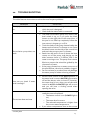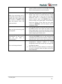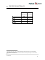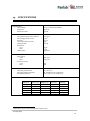
1
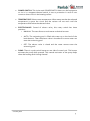
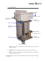
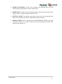
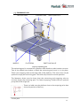
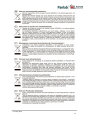
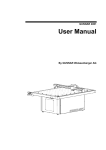
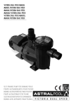
Hardware User’s Manual Circular pool Water maze Referencias: LE82090 (76-0020), LE820120 (76-0021), LE820140 (76-0022), LE820170 (76-0023), LE820200 (76-0024) Versión: V12/11/2014 Panlab, s.l.u C/Energía, 112 08940 Cornellà de Ll.(Barcelona) Spain www.panlab.com International Calls: +34 934 750 697 Domestic Call: 934 190 709 Fax: +34 934 750 699 [email protected] Limitación de las responsabilidades PANLAB no acepta la responsabilidad, bajo ninguna circunstancia, de cualquier daño causado directa o indirectamente por una interpretación incorrecta de las instrucciones detalladas a lo largo de este manual. Algunos símbolos pueden interpretarse de diversas maneras por profesionales que no estén acostumbrados a su uso. PANLAB se reserva el derecho a modificar, total o parcialmente, los contenidos de este documento sin previo aviso. 1. SYMBOLS TABLE Recognising the symbols used in the manual will help to understand their meaning: DESCRIPTION SYMBOL Warning about operations that must not be done because they can damage the equipment Warning about operations that must be done, otherwise the user can be exposed to a hazard. Protection terminal ground connection. Warning about a hot surface which temperature may exceed 65ºC Warning about a metal surface that can supply electrical shock when it’s touched. Decontamination of equipments prior to disposal at the end of their operative life Waste Electrical and Electronic Equipment Directive (WEEE) 2. GOOD LABORATORY PRACTICE Check all units periodically and after periods of storage to ensure they are still fit for purpose. Investigate all failures which may indicate a need for service or repair. Good laboratory practice recommends that the unit be periodically serviced to ensure the unit is suitable for purpose. You must follow preventive maintenance instructions. In case equipment has to be serviced you can arrange this through your distributor. Prior to Inspection, Servicing, Repair or Return of Laboratory Equipment the unit must be cleaned and decontaminated. Decontamination prior to equipment disposal In use this product may have been in contact with bio hazardous materials and might therefore carry infectious material. Before disposal the unit and accessories should all be thoroughly decontaminated according to your local environmental safety laws. Circular pool 1 3. UNPACKING AND EQUIPMENT INSTALATION WARNING: Failure to follow the instructions in this section may cause equipment faults or injury to the user. A. The swimming pool is bulky and heavy equipment. To unpack and lift the equipment you must use the right tools and machinery, you should check your local regulations to avoid injury unpacking and lifting the equipment. B. Inspect the instrument for any signs of damage caused during transit. If any damage is discovered, do not use the instrument and report the problem to your supplier. C. Ensure all transport locks are removed before use. The original packing has been especially designed to protect the instrument during transportation. It is therefore recommended to keep the original carton with its foam parts and accessories box for re-use in case of future shipments. Warranty claims are void if improper packing results in damage during transport. D. Place the equipment on a flat surface and leave at least 10 cm of free space between the rear panel of the device and the wall. Never place the equipment in zones with vibration or direct sunlight. E. Once the equipment is installed in the final place, the main power switch must be easily accessible. F. Only use power cords that have been supplied with the equipment. In case that you have to replace them, the spare ones must have the same specs that the original ones. G. Make sure that the AC voltage in the electrical network is the same as the voltage the equipment is made for (110V AC or 230V AC not selectable). Never connect the equipment to a power outlet with voltage outside these limits. For electrical safety reasons you only can connect equipment to WARNING power outlets provided with earth connections . This equipment can be used in installations with category II overvoltage according to the General Safety Rules. The manufacturer accepts no responsibility for improper use of the equipment or the consequences of use other than that for which it has been designed. Circular pool 2 PC Control Some of these instruments are designed to be controlled from a PC. To preserve the integrity of the equipment it is essential that the attached PC itself conforms to basic safety and EMC standards and is set up in accordance with the manufacturers’ instructions. If in doubt consult the information that came with your PC. In common with all computer operation the following safety precautions are advised. WARNING • To reduce the chance of eye strain, set up the PC display with the correct viewing position, free from glare and with appropriate brightness and contrast settings • To reduce the chance of physical strain, set up the PC display, keyboard and mouse with correct ergonomic positioning, according to your local safety guidelines. Circular pool 3 4. MAINTENANCE WARNING: Failure to follow the instructions in this section may cause equipment fault. PRESS KEYS SOFTLY – Lightly pressing the keys is sufficient to activate them. Equipments do not require being disinfected, but cleaned for removing urine, faeces and odour. To do so, we recommend using a wet cloth or paper with soap (which has no strong odour). NEVER USE ABRASIVE PRODUCTS OR DISSOLVENTS. NEVER pour water or liquids on the equipment. Once you have finished using the equipment turn it off with the main switch. Clean and check the equipment so that it is in optimal condition for its next use. For electrical safety reasons, never open the equipment. The power supply has dangerous voltage levels. WARNING Circular pool 4 5. TABLE OF CONTENTS 1. SYMBOLS TABLE 1 2. GOOD LABORATORY PRACTICE 1 3. UNPACKING AND EQUIPMENT INSTALATION 2 4. MAINTENANCE 4 5. TABLE OF CONTENTS 5 6. INTRODUCTION 7 7. EQUIPMENT DESCRIPTION 8 7.1. CONTROL UNIT 8 7.2. HEATING TANK 10 7.3. SWIMMING POOL 12 8. EQUIPMENT CONNECTION 13 9. EQUIPMENT SET-UP 14 9.1. SWIMMING POOL FILLING 14 9.2. WATER HEATING 15 10. LE820900 HEATER TANK CLEANING PROCEDURE 16 10.1. ITEMS SUPPLIED 16 10.2. CLEANING PROCEDURE 16 11. TROUBLESHOOTING 17 12. PREVENTIVE MAINTENANCE 19 13. SPECIFICATIONS 20 Circular pool 5 Circular pool 6 6. INTRODUCTION The LE 820 Automatic Swimming Pool is designed as an ideal component for swimming tests that can be performed with rats and mice. These experiments were described by Dr. Morris (Morris R.G.M. Learning and Motivation, 12:239, 1981). Figure 1. LE 820 Swimming pool. There are several sizes of swimming pools: Reference Diam. (cm) Height (cm) Volume (L) Weight Filled (Kg) LE 82090 90 60 350 420 LE 820120 120 60 620 705 LE 820140 140 60 850 960 LE 820170 170 60 1250 1387 LE 820200 200 60 1725 1893 WARNING: For anxiety experiments, the water is normally dyed white so that the animal cannot see the bottom of the pool. Never use latex for this purpose as it will damage the pump, level switch and resistor. Circular pool 7 7. EQUIPMENT DESCRIPTION 7.1. CONTROL UNIT POWER POWER HEAT WATER TEMPERATURE ELECTROVALVE Figure 2. Control unit. POWER LIGHT: Green light that remains on when POWER switch is in the ON position. HEAT LIGHT: Red light that remains on when the heater resistor is heating. Four conditions must be met for the heater resistor to heat the water: o The POWER switch must be in the ON position. o The water must be above the minimum heating level. o The protection temperature (50ºC) must not be exceeded. o The temperature regulation thermostat must have a temperature higher than the actual water temperature. WATER LIGHT: Yellow light that remains on when electro valve allows water to enter the swimming pool. Circular pool 8 POWER SWITCH: This is the main POWER SWITCH that turns the equipment on. As it is a magneto-thermal switch, it acts as protection in case of over current or short circuit in the heating resistor. TEMPERATURE: Selects water temperature. When water reaches the selected temperature it opens the circuit and the resistor will not work until the temperature falls below the selected value. ELECTROVALVE: Control of electro valve, this rotary switch has three positions: o MANUAL: The user allows as much water as desired to enter. o AUTO: The swimming pool is filled with water up to the level of the level detector. Then the electro valve is closed and no more water can enter the swimming pool. o OFF: The electro valve is closed and the water cannot enter the swimming pool. PUMP: There is a push switch button at one side of control unit. This button activates the pump while pressed. This manual activation of the pump helps when the heating tank is being cleaned. Circular pool 9 7.2. HEATING TANK MANUAL PUMP CONTROL UNIT POWER CORD 110V / 220V WATER OUTLET/INLET LEVEL HEATING RESISTOR WATER INLET ELECTRO VALVE WATER OUTLET/INLET PUMP Figure 3. Heating tank. LEVEL: Floating switch that detects when water reaches the minimum level necessary to heat. RESISTOR: The heating element that heats water. It has a power of 3 kW. PUMP: The pump moves water from the heating tank to the swimming pool to make temperature uniform. Circular pool 10 WATER OULET/INLET: Water flows between the heating tank and the swimming pool through the 2 water outlets/inlets. WATER INLET: Water enters the heating tank by flowing from the lab’s water supply system, passing through the electro valve. ELECTRO VALVE: The electro valve allows water into the swimming pool when it is activated in the AUTO or MANUAL control positions. MANUAL PUMP: There is a push button labelled MANUAL PUMP in left side of control unit box. It is used to test the pump and during the heater tank cleaning (see chapter 10). Circular pool 11 7.3. SWIMMING POOL HEATER TANK WHEELS CONTROL UNIT PLATFORM INLETS/OUTLETS EMPTYING VALVE Figure 4. Swimming pool. The swimming pool is mounted on a platform with wheels to make it easier to move. Two of the wheels have brakes to block the swimming pool once it is in its place. There is an emptying valve at the lower side of the platform. This valve must only be opened to empty the swimming pool. The valve stays closed in normal operation. The laboratory drain must be lower than the swimming pool emptying valve to correctly empty the swimming pool. For faster emptying, Panlab offers an optional pump with a flow of 900 l/h. There is a label over the platform close to the emptying valve that shows the position of the key. Circular pool 12 8. EQUIPMENT CONNECTION The electrical connections are simply connected to the mains AC power net by the power cord. The following schematic illustrates the hydraulic connections. Figure 5. Hydraulic connections. The necessary connections are listed in the following table: FROM 1 2 3 4 5 TO HOSE Swimming Pool inlet Pump outlet 18 mm x 12 mm Heater inlet/outlet Swimming Pool inlet/outlet 26 mm x 20 mm Heater inlet/outlet Swimming Pool inlet/outlet 26 mm x 20 mm Water supply system Heater inlet 26 mm x 20 mm Swimming Pool emptying valve Room water drain 26 mm x 20 mm Circular pool 13 9. EQUIPMENT SET-UP WARNING The pool is made specifically for 230V or 110V and the operating voltage is not selectable. The water pressure should not exceed 3bars for filling the pool. If installation pressure is higher, partially close the stopcock to reduce this pressure. 9.1. SWIMMING POOL FILLING 1) Before making the connection to the pool has to be noted that the drain valve is fully closed and that the entrance to the electro valve is connected to the water supply network. 2) It is advised that the laboratory has a water inlet with a stainless steel valve and hose barb with an inner diameter of 20 mm. 3) Connect the silicone tube in the heater transparent tube that acts as a vent. 4) Set the temperature selector to the minimum (0 °C) to not start heating. To do this, turn the dial counter-clockwise. 5) After checking all this and making the connection to the mains (220V or 110V AC) set the POWER switch to the (ON) position then the green light labelled POWER will turn on. 6) Set the valve control in the AUTO position and the pool will begin to fill up to the minimum level of the heater. While the pool is filling place the silicone breather tube into the pool. While the electro valve is allowing the ingress of water the yellow light labelled WATER will be on. If the inlet water pressure is high, you will see how the heater tank fills quickly and the swimming pool is filled through the water inlets. If at any time the level switch comes up you will hear a clicking sound and the yellow light labelled WATER turns off momentarily, do not worry the system will automatically reset. 7) Once the minimum water level is reached the electro valve will be closed and the yellow light turns off. The water recirculation pump will start running. Circular pool 14 8) Now move the valve control to MANUAL to finish filling the swimming pool (heater tank must be completely filled with water). While valve control is in the manual position WATER light stays on. 9) Once the swimming pool is filled remove the silicone breather from the pool and leave it hanging at the side of the heater tank. 10) Set the valve control to the centre position labelled OFF to close the electro valve. 9.2. WATER HEATING 1) After filling the pool (see section 9.1) and with the POWER switch set to ON and the valve selector set in the OFF position, turn the temperature selector clockwise to maximum (40°C), then the light labelled HEAT will turn on indicating that the swimming pool is heating. 2) Water in the tank will be warmed up; the recirculation pump takes water from the heater tank and leads it to the opposite end of the pool via a diffuser. The flow is around 8L/min to prevent the animal to note movement of the water. 3) Depending on the water temperature and the volume of water the pool will be heated to a maximum rate of 2-3 ° C/hour. During this time the HEAT light stays on all the time (it may turn off at a transitional moment but most of the time remain lit). 4) After one or two hours you should place the temperature selector to the temperature you want to keep the water, and the system will stabilize the temperature. 5) When necessary the light HEAT will turn on again. The system will maintain the temperature within 1°C of the target for the duration of the experiment. 6) If you want to know the current water temperature turn the temperature dial until you hear the shutter click of the thermostat, this is the current water temperature. WARNING: Due to the heat exchange with the environment, do not try to reach temperatures above 30 °C since in the end the system comes to equilibrium with the atmosphere and the water heating process would be too long. Circular pool 15 10. LE820900 HEATER TANK CLEANING PROCEDURE 10.1. - ITEMS SUPPLIED 1 Cleaner lance 2 Stainless clamps. 12/20 3 Meters glass reinforced hose 10.2. 007267 002246 002255 CLEANING PROCEDURE WARNING: The incoming water pressure must not exceed 3.5 bar. 1) Empty the pool. 2) Connect the end of the hose to a water valve (B) posting this with the provided steel clamp. 3) Remove the silicone tube/exhaust pipe elbow from the heater (A) 4) Enter the lance by the exhaust pipe. 5) Open the water valve and proceed to clean the tank heater. Effected cleaning must be done always up to down. 6) To prevent water from accumulating in the tank you should start recirculating water pump by pressing the button (D) while cleaning is being done. Figure 6. Procedure to clean the heater tank. NOTE: Do not use products that may contain alcohol to clean the tank heater. Circular pool 16 11. TROUBLESHOOTING This table features instructions to solve the most frequent problems. PROBLEM The equipment does not turn on. SOLUTION Recirculation pump does not work. Check that the mains voltage is the same for which the pool is designed. Check that the mains cable is connected. The water recirculation pump only works if the level switch is up, or if you press the black button on the right side of the control box. If the pool is not filled up completely follow the instructions in chapter 9.1 to fill it. Touch the body of the pump located under the heater tank to notice if it vibrates or not. Press the black button on the side of the control box and touch the pump to see if it vibrates. Reach into the pool in front of where the hose comes out of the pump, and playing on the sides because there is a diffuser feel if the water is moving or not. The pump flow is about 8l/min to prevent the animal be guided by the movement of water. If the pump vibrates but no water comes out of the pool diffuser, the tube is probably clogged. Do not use latex or products that may damage the water pump for white colouring of water. How can you check if water level is enough? Set the valve control in the AUTO position. If the water level is correct WATER light remains off and the electro valve is closed. If, however, the water level is low, when you set the valve control to AUTO the WATER light will turn on and you will hear a clicking sound when opening the valve. The resistor does not heat The resistor only will heat if the following condition are accomplished: o The heater control is on (POWER light is on). o The water level is correct. o The selected temperature is higher than the current water temperature. If you select a temperature close to the current Circular pool 17 water temperature, the HEAT light and the resistor will be turned on and turned off alone due to the temperature control system. When the swimming pool is being filled water level in the heater tank rises rapidly and this causes in AUTO mode that the electro valve will open and close. How can the swimming pool be emptied? How to know the water temperature of the pool if you do not have a thermometer? Can I cool the pool water? The water inlet pressure is high, this causes the heater tank level up faster because enters more water than it can exit to the pool. Whenever there is a rebound of level float switch, electro valve and WATER light will close and then will open again. At the end to finish the filling of the pool set the valve control to MANUAL until the heater tank is completely filled. Turn off the control or set the valve control in the OFF position and open the drain valve. When water level is low, press the black button on the side of the control unit so that the pump helps emptying the heater tank. Turn the temperature selector until it clicks and the light HEAT turns on, the temperature marked by the temperature selector when you hear the click is the current water temperature. The device only can heat the pool water. If the temperature selector selects a lower temperature than the current one it simply will not heat the water. The only way for water cooling is to wait for it to cool, or partially drain the pool and refill it with cold water. Circular pool 18 12. PREVENTIVE MAINTENANCE EXPERIMENT MONTHLY HEAT WATER EMPTY SWIMING POOL CLEANING HEATER TANK CLEAN WALLS AND FLOOR 1 2 3 1 Depending on the state of water, emptying frequency of the pool will be more or less frequent. Follow instructions in chapter 10. 3 While the pool is emptied you should clean walls and floor brushing thoroughly with a hard haired broom. 2 Circular pool 19 13. SPECIFICATIONS POWER SUPPLY Input voltage: Frequency: Maximum Power: 110 /230 VAC (not selectable) 50/60 Hz 3100 W WARMING SPECIFICATIONS Temperature range of the selector: Swimming poll max. temp.: Accuracy: Thermal protection switch: Heating Power: Resistance: 230 v: 110V: Heating rate: ELECTRICAL SPECIFICATIONS Main switch: 230V: 110V: Nominal current: 230V: 110V: 0ºC-40 ºC 4 ~32ºC +/-3 ºC 50ºC 3100 W 17,5 4,4 <3ºC/hour 16A 400V 32A 400V 13A 27A ENVIRONMENTAL CONDITIONS Operating temperature: Operating relative humidity: Storage temperature: 10°C to +40°C 0% to 85% RH, non-condensing 0°C to +50°C, non-condensing DIMENSIONS: Reference LE 82090 LE 820120 LE 820140 LE 820170 LE 820200 4 Diam. (cm) 90 120 140 170 200 Height (cm) 60 60 60 60 60 Volume (L) 350 620 850 1250 1725 Weight Filled (Kg) 420 705 960 1387 1893 Depending on environment temperature and pool size. Circular pool 20 DECLARACIÓN DE CONFORMIDAD DECLARATION OF CONFORMITY DECLARATION DE CONFORMITÉ Nombre del fabricante: Manufacturer’s name: Nom du fabricant: Panlab s.l.u. www.panlab.com [email protected] Dirección del fabricante: Manufacturer’s address: Adresse du fabricant: Energía, 112 08940 Cornellà de Llobregat Barcelona SPAIN Declara bajo su responsabilidad que el producto: Declares under his responsibility that the product: Déclare sous sa responsabilité que le produit: SWIMMING POOL Marca / Brand / Marque: PANLAB Modelo / Model / Modèle: LE820120, LE820140, LE820170, LE820200, LE82090, LE820900 Cumple los requisitos esenciales establecidos por la Unión Europea en las directivas siguientes: Fulfils the essential requirements established by The European Union in the following directives: Remplit les exigences essentielles établies pour l’Union Européenne selon les directives suivantes: 2006/95/EC 2004/108/EC 2012/19/EU 2011/65/EC 2006/42/EC Directiva de baja tensión / Low Voltage / Basse tensión Directiva EMC / EMC Directive / Directive CEM La Directiva de Residuos de Aparatos Eléctricos y Electrónicos (WEEE) / The Waste Electrical and Electronic Equipment Directive (WEEE) / Les déchets d'équipements électriques et électroniques (WEEE) Restricción de ciertas Sustancias Peligrosas en aparatos eléctricos y electrónicos (ROHS) / Restriction of the use of certain Hazardous Substances in electrical and electronic equipment (ROHS) / Restriction de l'utilisation de certaines substances dangereuses dans les équipements électriques et électroniques (ROHS) Directiva mecánica / Machinery directive / Directive mécanique Para su evaluación se han aplicado las normas armonizadas siguientes: For its evaluation, the following harmonized standards were applied: Pour son évaluation, nous avons appliqué les normes harmonisées suivantes: Seguridad / Safety / Sécurité: EMC: Safety of machinery: EN61010-1:2011 EN61326-1:2013 Class B EN ISO 12100:2010 En consecuencia, este producto puede incorporar el marcado CE: Consequently, this product can incorporate the CE marking: En conséquence, ce produit peut incorporer le marquage CE: En representación del fabricante: Manufacturer’s representative: En représentation du fabricant: Carme Canalís General Manager Panlab s.l.u., a division of Harvard BioScience Cornellà de Llobregat, Spain 27/05/2014 Circular pool 21 Circular pool 22