1
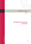
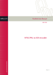
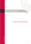
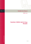
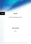
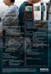
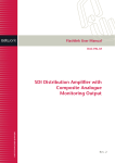
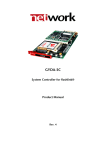
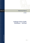
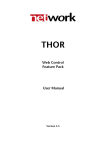
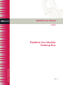
Flashlink User Manual
N-BOX
Flashlink One Module
Desktop Box
network-electronics.com
Rev. 2
N-BOX
Rev. 2
Network Electronics ASA
Thorøya
P.O. Box 1020
Sandefjord, Norway
Phone: +47 33 48 99 99
Fax: +47 33 48 99 98
E-mail: [email protected]
www.network-electronics.com
Service Phone: +47 90 60 99 99
Revision history
Current revision of this document is the uppermost in the table below.
Revision Replaces
2
1
0
1
0
-
Date
Change description
2007-10-26 New front page and removed old logo.
2007-10-05 Added Materials Declaration and EFUP
23/05/05 NBS: Initial Revision.
2
N-BOX
Rev. 2
Contents
Revision history............................................................................... 2
1 Product overview......................................................................... 4
2 Specifications .............................................................................. 4
2.1 General specifications ..................................................................................4
2.2 Front view ...................................................................................................4
2.3 Rear view.....................................................................................................4
3 Configuration .............................................................................. 5
3.1 Address setting on each N-BOX...................................................................5
4 Connections ................................................................................ 5
4.1 Power connection........................................................................................5
4.1.1 Pin-out DC input
5
4.2 Module connections ....................................................................................5
5 N-BOX operation......................................................................... 6
5.1 Removing the front panel ............................................................................6
5.2 Card removal...............................................................................................6
5.3 Back plane insertion.....................................................................................7
5.4 Card insertion..............................................................................................7
6 N-BOX configuration examples ................................................... 8
6.1 N-BOX in a 1RU frame.................................................................................8
6.2 N-BOX mounting brackets ..........................................................................8
Certificate of Conformity .............................................................. 10
Product Warranty ......................................................................... 11
Materials declaration and recycling information............................ 12
Materials declaration .................................................................... 12
Environmentally-friendly use period .............................................. 12
Recycling information................................................................... 13
3
N-BOX
Rev. 2
1 Product overview
The N-BOX is meant to meet the need for a one module desktop box for
®
flashlink module cards. This box shall use the same backplane as in the
standard 2RU frame. This means that the modules and backplanes can be
removed from a desktop box and replaced into the FR-2RU-10-2 frame.
In addition, 4 desktop boxes can be assembled together into a 1 RU box
holder and function as a 1 RU unit.
2 Specifications
2.1 General specifications
AC Power:
DC Power:
Dimensions:
Card slots:
Internal voltages:
External power supplies 100 - 260 VAC
±15V, connector DB9 male
109 x 43 x 198 mm.
1.
+5V, -5V, +15V, -15V.
2.2 Front view
The front view of the N-BOX shows status LEDs for the module that is
included in the N-BOX.
Figure 1: LEDs in front of the N-BOX.
1
The leftmost LED of each module card is a "general status" LED.
- Green light means that the card is OK.
- Red light means that the card is faulty.
- No light means that the power is not switched on.
The meaning of each LED on the module cards is described in their respective
manuals.
2.3 Rear view
Figure 2 shows an example of an N-BOX seen from the rear side.
To the left is the connector module for the power supply delivered with the NBOX. The other connector modules are described in their respective user
manuals.
1
LEDs from left to right when box is viewed as in this figure.
4
N-BOX
Rev. 2
Figure 2: Rear view of an N-BOX.
3 Configuration
3.1 Address setting on each N-BOX
Each N-BOX can be assigned an address through the address selector on the
underside of the box. Maximum 8 addresses are available.
This address setting only applies when your application includes more than
one N-BOX. The addresses represent card positions in a FR-2RU-10-2 frame,
and are numbered from 0 – 9.
Default address/card position is 0.
4 Connections
4.1 Power connection
DC: Connect the DB9 connector from the external DC power supply to the
DB9 male connector of the N-BOX. Tighten the screws to ensure a proper
contact.
4.1.1 Pin-out DC input
The maximum current drawn from each pin of the DB9 connector is 2,5A.
Pin #1
Pin #2
Pin #3
Pin #4
Pin #5
Pin #6
Pin #7
Pin #8
Pin #9
0V / GND
+5V
Tx(+)
+15V
Rx(-)
Rx(+)
Tx(-)
-15V
0V / GND
Reserved.
Output from module.
DC Input.
Output from module.
Output from module.
Output from module.
DC Input.
4.2 Module connections
The other connectors are module specific; hence they are described in their
respective user manuals.
5
N-BOX
Rev. 2
5 N-BOX operation
In order to reconfigure an N-BOX, the front panel must be removed. Each
module has a corresponding connector module at the rear, and is hot
swappable.
Note!
Use safety goggles when hot-swapping module cards.
If a receiver card is removed from the N-BOX, an invisible laser
beam may be emitted inside the N-BOX from the laser at the
other end. The laser beam might be harmful to your eyes.
5.1 Removing the front panel
Detach the front panel by unfastening the two screws fixing the front panel.
Use a TX-08 screwdriver for this. A TX-08 screwdriver is included in the
shipment of your N-BOX.
Figure 3: Removing the front panel.
5.2 Card removal
To remove a module card from the N-BOX frame, release the card by moving
the red handle until it is in horizontal position. Then pull the card out of the
N-BOX with the red handle. After removing a card, it is important that the
protective cap is put back on the ferrule tip.
Note!
When removing a receiver card from the N-BOX (hot
swapping), the laser beam may be present inside the N-BOX
(transmitted through the fiber). To avoid damaging your eyes,
never look directly into the N-BOX unless you are 100 % sure
that no laser beam is present inside the N-BOX.
6
N-BOX
Rev. 2
5.3 Back plane insertion
You must install the accompanying back plane card before you can insert a
new module card into the frame.
Turn off the power by disconnecting the DB9 power contact to the N-BOX.
Remove the module card from the box, according to the procedure in
Chapter 5.1. Please follow anti-static procedures when handling circuit boards
with active components.
Remove all 4 screws from the back plane to be replaced. Remove the back
plane by lifting it straight out from the rear of the frame.
Insert the new back plane and tighten the screws.
Figure 4: Removing/inserting back plane.
5.4 Card insertion
After the front panel is removed, full access to the card modules inside the NBOX is given.
The N-BOX is equipped with guide rails to align the module card into its
position.
7
N-BOX
Rev. 2
6 N-BOX configuration examples
6.1 N-BOX in a 1RU frame
®
It is possible to mount up to four flashlink N-BOX modules into a 19” 1RU
frame, as shown below.
Figure 5: N-BOX in a 1RU frame.
Please contact Network Electronics ASA for further information about the
mounting kits.
6.2 N-BOX mounting brackets
ETH-CON modules may also be mounted against walls, under desks, etc. The
figure below shows available mounting plates for ETH-CON.
Figure 6: Mounting plates for the N-BOX.
The following examples show how to apply the available mounting kits.
8
N-BOX
Rev. 2
Figure 7: Wall – Under desk - Wall.
Figure 8: Between wall/desk – Wall - Under desk.
Figure 9: Wall - Under desk.
Please contact Network Electronics ASA for further information about the
mounting kits.
9
N-BOX
Rev. 2
Certificate of Conformity
Network Electronics ASA
N-3204 Sandefjord
Norway
Company Registration Number:
NO 976 584 201 MVA
Declares under sole responsibility that the product:
Product Name:
N-BOX
Product Description:
flashlink® one module desktop box
To which this declaration relates are of Norwegian origin and are in conformity with
the following standards:
EN 55103-1: 1996
Generic Emissions Standard
EN 55103-2: 1996
Generic Immunity Standard
10
N-BOX
Rev. 2
Product Warranty
The warranty terms and conditions for the product(s) covered by this manual follow the
General Sales Conditions by Network Electronics ASA. These conditions are available
on the company web site of Network Electronics ASA:
www.network-electronics.com
11
N-BOX
Rev. 2
Materials declaration and recycling information
Materials declaration
For product sold into China after 1st March 2007, we comply with the “Administrative
Measure on the Control of Pollution by Electronic Information Products”. In the first
stage of this legislation, content of six hazardous materials has to be declared. The table
below shows the required information.
Toxic or hazardous substances and elements
組成名稱
Part Name
N-BOX
鉛
汞
镉
六价铬
多溴联苯
多溴二苯醚
Lead Mercury Cadmium Hexavalent Polybrominated Polybrominated
(Pb)
(Hg)
(Cd)
Chromium
biphenyls
diphenyl ethers
(Cr(VI))
(PBB)
(PBDE)
X
O
O
O
O
O
O: Indicates that this toxic or hazardous substance contained in all of the homogeneous materials for
this part is below the limit requirement in SJ/T11363-2006.
X: Indicates that this toxic or hazardous substance contained in at least one of the homogeneous
materials used for this part is above the limit requirement in SJ/T11363-2006.
Environmentally-friendly use period
The manual must include a statement of the “environmentally friendly use period”.
This is defined as the period of normal use before any hazardous material is released to
the environment. The guidance on how the EFUP is to be calculated is not finalised at
the time of writing. See
http://www.aeanet.org/GovernmentAffairs/qfLeOpAaZXaMxqGjSFbEidSdPNtpT.pdf
for an unofficial translation of the draft guidance. For our own products, Network
Electronics has chosen to use the 50 year figure recommended in this draft regulation.
Network Electronics suggests the following statement on An “Environmentally Friendly
Use Period” (EFUP) setting out normal use:
EFUP is the time the product can be used in normal service life without leaking the hazardous materials.
We expect the normal use environment to be in an equipment room at controlled temperature range
(0ºC - 40ºC) with moderate humidity (< 90%, non-condensing) and clean air, not subject to vibration or
shock.
Further, a statement on any hazardous material content, for instance, for a product that
uses some tin/lead solders:
Where a product contains potentially hazardous materials, this is indicated on the product by the
appropriate symbol containing the EFUP. The hazardous material content is limited to lead (Pb) in some
solders. This is extremely stable in normal use and the EFUP is taken as 50 years, by comparison with the
EFUP given for Digital Exchange/Switching Platform in equipment in Appendix A of “General Rule of
Environment-Friendly Use Period of Electronic Information Products”. This is indicated by the product
marking:
50
12
N-BOX
Rev. 2
It is assumed that while the product is in normal use, any batteries associated with real-time clocks or
battery-backed RAM will be replaced at the regular intervals.
The EFUP relates only to the environmental impact of the product in normal use, it does not imply
that the product will continue to be supported for 50 years.
Recycling information
Network Electronics provides assistance to customers and recyclers through our web
site http://www.network-electronics.com. Please contact Network Electronics’
Customer Support for assistance with recycling if this site does not show the
information you require.
Where it is not possible to return the product to Network Electronics or its agents for
recycling, the following general information may be of assistance:
Before attempting disassembly, ensure the product is completely disconnected from
power and signal connections.
All major parts are marked or labelled to show their material content.
Depending on the date of manufacture, this product may contain lead in solder.
Some circuit boards may contain battery-backed memory devices.
13